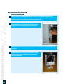
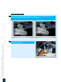
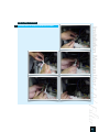
1
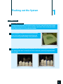
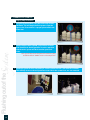
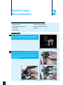
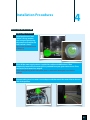
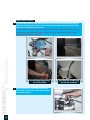
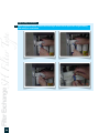
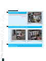
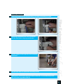
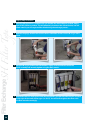
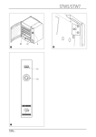
Technical & Repair guide for ChungHo Products
CHUNG HO DEALER Technical Guide
call 888.758.1234 for further technical support
Table of Contents
2
1. Designation of Components
1-1. Front
1-2. Interior
1-3. Back
page 3-5
2. Product Features
page 6-9
3. Exploded Diagram
3-1. Overall Exploded Diagram
3-2. Exploded Diagram of Ice Making Department
page 10-11
4. System Diagram
4-1. Water Purification Procedure
4-2. Ice Making Procedure
page 12
5. Distribution Line Diagram
page 13
6. Product Specification
page 14
7. Installation Precautions
page 15
8. Relocation/Installation Precautions
page 16
9. Installation
page 17
10. Usage
10-1. Display
10-2. Water Dispensing & Buttons
10-3. Operational Beep
10-4. Select/Deselect Function
10-5. Ice and Water Dispensing
10-6. Understanding the Ice Making Process and Operation
page 18-22
11. Test Board
page 23
12. Examination/Repair Procedure
page 24-53
13. Exploded Diagram & Parts List
page 54-57
Flushing out the System
1
1-1 Iguassu ice
Step by Step Instruction
1
In order to properly install a unit at the customer site, the system will have to be flushed
an additional two-three times to ensure customer satisfaction. This can take place either
at the dealer location or on site with the customer.
2
After installation, always ensure that the purification
process has begun by opening up the Ambient tank
lid and observing the functioning water purification.
3
Locate the flush valve by removing the Bottom-front cover from the Iguassu Ice (see below). Attach to the drain a shortened 3/8” hose so that the system may completely flush
out. (see left)
3
1-1 iguassu ice (cont’d)
Flushing
out
of
the
System
Step by Step Instruction
4
4
To open up the hot flush, turn the flush valve counterclockwise. This will begin the flush process from the
Iguassu Ice. Ensure there is a proper place to flush the
water into.
5
Underneath the label “DRAIN”, you will find a button
that should be in the Off position. Turn this switch On
and the entire system will drain out the open flush
valve.
Note: System LEDs on the font panel will continuously ding
and blink while the “DRAIN” switch is in the ON position.
6
Allow the system to drain completely 2~3 times before the unit is left with the customer.
This will help to ensure that any odorous tastes left in the system lines, etc. are removed.
1-2 all other units
Step by Step Instruction
In order to properly install a unit at the customer site, the system will have to be flushed
an additional two-three times to ensure customer satisfaction. This can take place either
at the dealer location or on site with the customer.
2
After installation, always ensure that the purification
process has begun by opening up the Ambient tank lid
and observing the functioning water purification.
3
Locate drain device (as shown below). Lift Cold lever up and immediately attach the
device, latching the hook to ensure stability in draining. Repeat with the Hot lever for all
units. Ensure there is a proper place to drain the water into.
Y2K-III Only
3
Flushing out the
System
1
Locate drain device (as shown below). Lift up lever and immediately attach the device,
latching the hook to the lever to ensure stability in draining (see below). Ensure there is a
proper place to drain the water into.
5
2
Check for Leaks /
Hose Connections
When checking for leaks, please adhere to the following checklist:
1) Booster Pump
2) Under sink connections
3) All tubing running to unit
4) In line (Direct) connections
5) 3/8” drain
6) Filters
7) WLD Sensor
How to Diagnose
6
1
Booster Pump
Make sure to check the connections to and from the
booster pump. They could have loosened in transit.
2
Under sink connections
Tighten all connections with your hands and ensure
proper stability. Then check for leaks by turning on
the water. Continue to tighten as necessary to control any leaking.
3
Check for Leaks
Hose
Connections
How to Diagnose
All Tubing Running to Unit
Ensure that all tubing is connected properly and that there are no leaks as it runs from the
water source to the unit. (Note: Check tubing within the mould before closing it up).
7
Check
for
Leaks
Hose Connections
8
How to Diagnose
4
In-line (Direct) connections
Make sure to check the connections to the back of the
unit: Inlet, Brine and Drain (if applicable) are securely
inserted.
5
3/8” Water
A leak can occur due to the 3/8” drain line water for a
few different reasons:
1) Connection from the drip pan is not secured or is
not draining properly.
2) Water from the melted Ice is not draining properly
In order to resolve:
ºPlease install a sump pump (see diagram)
Recommended pump:
ºLittle Giant, Part#2P350
6
Tighten Filters
In transit, the S/H filter type can/may become loose.
To prevent from future leaks, tighten the filters before installation with a filter wrench.
3
Check for Leaks
Hose
Connections
How to Diagnose
Water Level Detector Defective
If the Ambient tank overflows, then the OLC (Overflow Level Control) has gone defective.
9
Test Board Connections
Iguassu Ice & Ice Combo Plus
3
Test Board Connection
The test board connectors are located at top of the unit, with the front and top covers removed.
(see below)
Test Board
Connection
Iguassu Ice
10
Ice Combo Plus
Installation Procedures
4
Basic POU Installation
Step by Step Instruction
1
Install product on a level
surface. (Chang product
level using the product leg
adjustment and confirm the
level surface is level.)
Iguassu Ice: Use level found
in drip tray
2
Close off the water supply valve as supplied to each household/business. Then
temporarily remove the connector part as provided from your given water source. Then,
connect the main water line adaptor.
If the sealing O-ring at the connection piece is removed or damaged, it can lead to
leakage.
3
Connect tubing hose into water source adaptor and then attach the water inlet on the rear
side of the product.
11
Step by Step Instruction
Installation
Procedures
4
12
Connect tubing hose into the removed water (brine) and drained water connection part
of the rear side of product and then connect tubing hose into the drainage hole in sink,
bathroom, or multi-purpose room, etc.
Install the removed water (brine) line and drained water line separately. If drainage does
not function properly due to improper installation, then water may flow back toward
waterspout and cause an overflow.
Into the Sump Pump from
3/8” Drain Outlet
5
Open the angle stop valve supplied into each
household, and place the water source adaptor
to the open position.
Out from the Sump Pump
via 3/8” hose to drain
Step by Step Instruction
Check to see if water is leaking at each connection part.
(Refer to previous section)
7
For stabilization of the cooling system and for safe use of this product, insert the power
plug into an AC 110V/60Hz, 220/50z, 240V/50Hz, and 220V/60Hz power outlet after 30
minutes after installation of the product.
8
Check whether water is supplied into the Ambient tank and whether there is any leakage
in or around the tubing connections.
(Refer to previous section)
9
Check whether water is coming out by pressing the water dispensing button 1 hour after
purification has begun.
10
Ensure that the drip pan is draining properly.
Poor water into the drip pan (see below).
Installation Procedures
6
13
DOs & DON’Ts
What to look for:
14
5
1
Surrounding Temperatures
When installing systems, avoid locations that expose system to excessive heat, flames, and/or
locations affected by humidity, direct sunlight, rain or snow.
2
Water Pressure
Water pressure should read between 50-80 PSI. This is the ideal measurement for proper water
purification. Please install a Booster Pump if lower than 50 PSI. Conversely, please apply a PSI reducer
when pressure reads greater than 80 PSI.
3
Total Dissolved Solids
Water quality is of utmost importance when dealing with a Reverse Osmosis system. In order to
achieve the best possible purification, please check TDS of incoming water sources. Those sources
greater than 500-600 TDS may cause a problem..
4
System Transport
Do not tilt the system more than 45 degrees when moving. Excessive tilting may cause cooling
malfunction.
5
System Placement
Allow 18 inches of space between system and wall for proper ventilation.
6
Installation
Do not bend tubing when connecting system to water source nor place heavy objects on the tubing.
May restrict sufficient water flow and reduce water purification.
7
Installation II
Make sure that all tubing (inlet, brine and drainage) are securely connected to the fitting on the back
of the system to prevent water leaks. Water leaked from the system may cause electric shock and/or
fire.
Installation Manual for
UV Filter Assembly (Model : UV 401)
6
6-1 Necessary Materials
1
Transformer
2
UV Filter
3
UV Clip
4
UV Bracket
5
UV Filter Assembly
6
1/4” Tubing
15
6-2 Installation Procedure
Installation
Manual
for
UV Filter
Step by Step Instruction
16
1
Halt the water flow and purification process to the Ice Combo before attempting to
install the UV Filter. You will have to remove the filter block and assembly, so to avoid
complications be sure the main water line attachment is OFF.
2
Remove the front cover to the Ice Combo Plus in order
to gain access to the main filter housing area and to
reveal the filter block.
3
Remove tubing attached to the main drain line to ease the process of removing the Filter
Assembly.
4
Remove the front cover to the Ice Combo Plus in order
to gain access to the main filter housing area and to
reveal the filter block.
Step by Step Instruction
Place UV Filter assembly between filter bracket and single-head bracket and turn it
upward.
6
Tighten it down with 12 4* screws (Place screws
only on one side if not fitted).
Installation Manual for UV
Filter
5
17
Installation
Manual
for
UV Filter
Step by Step Instruction
18
7
Measure out the proper tubing length for connection to the Post Carbon Filter. Connect
the UV Filter IN to the Post Carbon OUT with a 1/4” tubing.
8
Place Filter assembly back into original position.
Link to transformer line.
Step by Step Instruction
Connect the transformer to with the UV Filter.
Installation Manual for UV
Filter
9
19
7
Filter ExchangeSH Filter Type
Filter Exchange Guide
S/H Filter Type
20
7-1 Necessary Materials
1
Sediment Filter
2
Pre-Carbon Filter
3
Membrane Filter
4
Post-Carbon Filter
5
Filter Wrench
6
Purge Attachment
7-2 setup procedure
Step by Step Instruction
Halt the water flow and purification process to the Ice Combo before attempting to
replace filters. To avoid complications, be sure the main water line attachment is in the
OFF position.
2
Remove the front cover to the Ice Combo Plus in order to
gain access to the main filter housing area and to reveal
the filter block.
3
Ensure all tubing and assembly, as related to the filter block, is attached and in working
condition. This will help to avoid unwanted accidents following the filter change.
4
Once you have checked the product in detail,
proceed with the following steps for proper filter
exchange.
Filter Exchange
SH
Filter
Type
1
21
7-3 sediment filter
Filter ExchangeSH Filter Type
Step by Step Instruction
22
1
Loosen Sediment Filter with Filter Wrench.
2
Unscrew the filter from the filter block.
3
Make sure to always remove the O-ring from any
filter. This ring must be passed from filter to filter
through all changes to prevent against unwanted
leaks and to ensure quality water production.
4
Replace the O-ring from the old Sediment Filter and
place into the new filter.
Note: Never use non-ChungHo Nais manufactured filters.
It can highly degrade the quality and efficiency of the
product.
Step by Step Instruction
Once the O-ring is placed back into the filter, simply screw the filter back into the block
assembly and securely tighten using the filter wrench.
6
It is important to note that on all filters,
the place marker (seen below) must
be situated to the right of the name of
filter type (i.e. SEDI). You will have to
tighten the filters with the filter wrench
accordingly.
Place
Marker
Filter Exchange
SH
Filter
Type
5
23
7-4 pre-carbon filter
Filter ExchangeSH Filter Type
Step by Step Instruction
24
1
Loosen Pre-Carbon Filter with Filter Wrench.
2
Unscrew the filter from the filter block.
3
Make sure to always remove the O-ring from any
filter. This ring must be passed from filter to filter
through all changes to prevent against unwanted
leaks and to ensure quality water production.
4
Replace the O-ring from the old Pre-Carbon Filter
and place into the new filter.
Note: Never use non-ChungHo Nais manufactured filters.
It can highly degrade the quality and efficiency of the
product.
Step by Step Instruction
In connecting the Pre-Carbon filter, you will have to first purge the filter, effectively
removing excess carbon from the inner casing. Before purging the filter, make sure to tap
up and down the filter from all sides. This will allow more loose carbons to be released so
that they may be expelled from the system via the purge process.
6
For this step, you will utilize the purge attachment
as is mentioned in the necessary parts list.
7
Screw on the attachment until it is tightly secured on the Pre-Carbon filter head.
8
Temporarily remove red clip and blue tubing (see below) to make way for purge.
Filter Exchange
SH
Filter
Type
5
25
Filter ExchangeSH Filter Type
Step by Step Instruction
26
9
Replace with additional hose (1-2 ft.) connected from the filter block to the purge
attachment.
10
Attach a third hose to the opposite end of the purge
attachment.
11
Turn the main water line attachment to the ON position.
12
Allow the Pre-Carbon filter to purge for about
10 minutes. This will effectively rid the filter of
unnecessary carbon build-up.
Step by Step Instruction
After the purge process is complete, do not shut OFF the water adaptor. Instead, simply
turn off the power to product. This will effectively shut down the solenoid valve, and not
allow water to pass through the filter block during the exchange process.
14
Remove the purge attachment from the Pre-Carbon filter and ensure the O-ring is still in
place.
15
Once the O-ring is placed back into the filter, simply screw the filter back into the block
assembly and securely tighten using the filter wrench.
16
Remember that it is important to note that on all filters, the place marker must be situated
to the right of the name of filter type (i.e. PRE). You will have to tighten the filters with the
filter wrench accordingly.
Filter Exchange
SH
Filter
Type
13
27
Step by Step Instruction
Filter ExchangeSH Filter Type
17
28
Upon completion of Pre-Carbon filter exchange, make sure to replace the original tubing
and red clip as seen below.
7-5 membrane filter
Step by Step Instruction
Remove the red clip and hose attached to the bottom of the Membrane Filter.
2
Loosen Membrane Filter with Filter Wrench.
3
Unscrew the filter from the filter block.
4
Make sure to always remove the O-ring from any
filter. This ring must be passed from filter to filter
through all changes to prevent against unwanted
leaks and to ensure quality water production.
Filter Exchange
SH
Filter
Type
1
29
Filter ExchangeSH Filter Type
Step by Step Instruction
30
5
Replace the O-ring from the old Membrane Filter
and place into the new filter.
Note: Never use non-ChungHo Nais manufactured
filters. It can highly degrade the quality and efficiency
of the product.
6
Once the O-ring is placed back into the filter, simply screw the filter back into the block
assembly and securely tighten using the filter wrench.
7
Remember that it is important to note that on all filters, the place marker must be situated
to the right of the name of filter type (i.e. MEM). You will have to tighten the filters with the
filter wrench accordingly.
7-6 Post-Carbon Filter
Step by Step Instruction
Loosen Post-Carbon Filter w/ Filter Wrench.
2
Unscrew the filter from the filter block.
3
Make sure to always remove the O-ring from any
filter. This ring must be passed from filter to filter
through all changes to prevent against unwanted
leaks and to ensure quality water production.
4
Replace the O-ring from the old Post-Carbon Filter
and place into the new filter.
Note: Never use non-ChungHo Nais manufactured filters.
It can highly degrade the quality and fficiency of the
product.
Filter Exchange
SH
Filter
Type
1
31
Filter ExchangeSH Filter Type
Step by Step Instruction
32
5
In connecting the Post-Carbon filter, you will have to first purge the filter, effectively
removing excess carbon from the inner casing. Before purging the filter, make sure to tap
up and down the filter from all sides. This will allow more loose carbons to be released so
that they may be expelled from the system via the purge process.
6
For this step, you will utilize the purge
attachment as is mentioned in the necessary
parts list.
7
Screw on the attachment until it is tightly secured on the Post-Carbon filter head.
Step by Step Instruction
Temporarily remove red clip and blue tubing (see below) to make way for purge.
9
Replace with additional hose (1-2 ft.) connected
from the filter block to the purge attachment.
10
Attach a third hose to the opposite end of the purge
attachment.
11
Turn the main water line attachment to the ON position.
12
Allow the Post-Carbon filter to purge for about 10 minutes. This will effectively rid the
filter of unnecessary carbon build-up.
Filter Exchange
SH
Filter
Type
8
33
Filter ExchangeSH Filter Type
Step by Step Instruction
34
13
After the purge process is complete, do not shut OFF the water adaptor. Instead, simply
turn off the power to product. This will effectively shut down the solenoid valve, and not
allow water to pass through the filter block during the exchange process.
14
Remove the purge attachment from the Post-Carbon filter and ensure the O-ring is still in
place.
15
Once the O-ring is placed back into the filter, simply screw the filter back into the
block assembly and securely tighten using the filter wrench.
16
Remember that it is important to note that on all filters, the place marker must be situated
to the right of the name of filter type (i.e. POST). You will have to tighten the filters with
the filter wrench accordingly.
Step by Step Instruction
17
Upon completion of Post-Carbon filter exchange, make sure to replace the original tubing
and red clip as seen below.
Filter Exchange
SH
Filter
Type
35
ChungHo USA
1240 N. Simon Circle Suite A
Anaheim CA 92806
888.758.1234
www.chunghousa.com
[email protected]