1
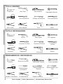
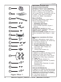
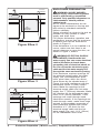
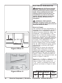
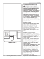
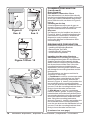
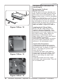
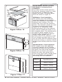
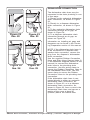
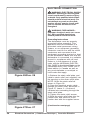
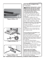
BOSCH Customer Care
1 of 1
Search
http://www.boschappliances.com/customer_care/default_SHX33A0xUC_...
Dealer Locator
Contact Us
Terms of Use
9.7.2005
Installation Instructions for Bosch Integra 300 Series Dishwashers
SHX33A0xUC
Here you can download a printable version of the Installation Instructions for your product.
Adobe Acrobat is required to view this file. Click here to download Adobe Acrobat.
Download Installation Instructions
Add Page To My Favorites
View My Favorites
SHX/SHV Dimensions: Dimensions for planning only. For details see installation manual.
Specifications subject to change without notice.
†
Maximum height of 36" possible with toe-kick from cabinet supplier.
9/7/2005 2:08 PM
DISHWASHER
Installation
Instructions
LAVE-VAISSELLE
Instructions
d’installation
LAVADORA DE PLATOS
Instrucciones
de instalación
Cycle Countdown
Power
Scrub
Plus
On/Off
Scrub
Wash
Regular
Wash
Delicate/
Econo
Quick
Wash
Rinse
& Hold
Refill
Rinse
Agent
On /Off
Power Scrub
Power
Delay
Start
Hours
Top
Rack
Only
Rinse
& Hold
Cancel
Drain
SHI66A,
SHU33A, SHU43C, SHU53A, SHU66C,
SHU43E, SHU53E, SHU66E,
SHV46C, SHV66A, SHV99A
SHX33A, SHX46A, SHX46B,
SHX56B, SHX99B
SHY56A, SHY66C, SHY99A
Regular
Wash
Cycles
Power
High
Temp
Wash
Regular
Temp
Wash
Temp.Options
Rinse
&
Hold
Table of Contents
Placing the Dishwasher ...................
Securing the Dishwasher .................
Drain Hose Connection ....................
Hot Water Connection .....................
Electrical Connection .......................
Door Tension Adjustment .................
Base and Toe Panel ........................
Final Instructions .............................
Customer Service ............................
20
20
22
24
26
28
28
30
30
English
IMPORTANT INSTRUCTIONS ...... 2
Tools Needed ................................. 4
Materials Needed ........................... 5
Materials Supplied ......................... 6
Enclosure Preparation ................... 8
Electrical Preparation .................. 10
Plumbing Preparation .................. 12
Dishwasher Preparation ............... 14
Door Panel Installation ................. 18
Table des Matières
Emplacement ..................................
Fixation du lave-vaisselle .................
Connexion du tuyau de vidange .......
Connexion eau chaude ....................
Connexion électrique .......................
Réglage tension de la porte .............
Base et Panneau inférieur ...............
Instructions finales ...........................
Service à la clientèle ........................
21
21
23
25
27
29
29
31
31
Français
INSTRUCTIONS IMPORTANTES .. 2
Outils nécessaires ........................ 4
Matériaux nécessaires ................. 5
Matériaux fournis .......................... 7
Mise en oeuvre ............................. 9
Préparation électrique ................. 11
Préparation de la plomberie ........ 13
Préparation du lave-vaisselle ....... 15
Installation panneau de porte ...... 19
Tabla de Materias
INSTRUCCIONES IMPORTANTES ............. 2 Como Situar la Lavadora .................. 21
Como Afirmar la Lavadora ................
Conexión - Manguera de Desagüe ...
Conexión de Agua Caliente ..............
Conexión Eléctrica ..........................
Ajustar la Tensión de la Puerta ........
Base y Panel de Pie ........................
Instrucciones Finales .......................
Servicio al Cliente ............................
Table of Contents | Table des Matières | Tabla de Materias
21
23
25
27
29
29
31
31
1
Español
Herramienta Necesaria ....................... 4
Materiales Necesarios ........................ 5
Materiales Provistos ........................... 7
Preparación del Gabinete ................... 9
Preparación - Sistema Eléctrico ........ 11
Preparación - Plomería ...................... 13
Preparación de la Lavadora ................ 15
Instalación -Panel de la Puerta .......... 19
English
VERY IMPORTANT INSTRUCTIONS - TO BE READ
WARNING - OBSERVE ALL WARNINGS AND CAUTIONS
These instructions are intended for use by qualified installers only.
Français
In addition to these instructions, the dishwasher shall be installed:
• In accordance with all local codes or, in the absence of a local code,
• In the United States, with the National Electric Code.
• In Canada, with the Canadian Electric Code C22.1 -latest edition/Provincial and
Municipal codes and/or local codes.
Read these installation instructions completely and follow them carefully. They will
save you time and effort and help to ensure safety and optimum dishwasher performance.
CAUTION: If the dishwasher is installed in a location that experiences freezing temperatures (e.g., in a holiday home), you must drain all the water from the dishwasher’s
interior. Turn off the water supply, disconnect the drain hose, and allow your dishwasher to completely drain into an appropriate receptacle. Water system ruptures that
occur as a result of freezing are not covered by warranty.
INSTRUCTIONS IMPORTANTES À LIRE
AVERTISSEMENT- OBSERVER ET LIRE TOUS LES AVERTISSEMENT
Ces instructions sont destinées à un installateur qualifié seulement.
Español
En plus de ces instructions, le lave-vaisselle doit être installé :
• Conformément à tous les codes locaux, ou en l’absence de ceux-ci,
• aux États-Unis, avec le code national de l’électricité.
• au Canada, ave le code C22.1, dernière édition du code canadien d’électricité/codes
provinciaux et municipaux et/ou les codes locaux.
Lire entièrement ces instructions d’installation et les observer. Elles permettront
d’économiser temps et argent et assureront un rendement sécuritaire et optimal du
lave-vaisselle.
ATTENTION : Si le lave-vaisselle est installé dans un endroit où il peut y avoir du gel
(ex. : dans un chalet), il faut vidanger l’eau de l’intérieur de l’appareil. Fermer
l’alimentation en eau, débrancher le tuyau de vidange et laisser l’appareil se vider
complètement dans un récipient. Les ruptures de système d’eau résultant du gel ne
sont pas couvertes par la garantie.
INSTRUCCIONES MUY IMPORTANTES - POR FAVOR LÉALAS
CUIDADO - CUMPLA CON TODOS LOS AVISOS Y ADVERTENCIAS
El fin de estas instrucciones es el de guiar únicamente al instalador capacitado.
Además de cumplir con estas instrucciones, instale la lavadora:
• Conforme a todos los códigos municipales o en caso de que éstos no existan...
• En Estados Unidos, conforme al Código Eléctrico Nacional [National Electric Code].
• En Canadá, conforme al Código Eléctrico Canadiense C-22.1-última versión, y los
códigos Provinciales y Municipales o locales.
Lea completamente estas instrucciones de instalación y cumpla con ellas
cuidadosamente. Guiándose por ellas, usted ahorrará tiempo y empeño, reducirá los
riesgos y asegurará un desempeño óptimo de su lavadora de platos.
CUIDADO: Si instala la lavadora en un sitio donde corre riesgo de congelación (tal
como en una casa campestre vacacional), usted debe evacuar toda el agua del
interior de la lavadora. Cierre la alimentación de agua, desconecte la manguera de
desagüe y permita que la lavadora se vacíe completamente en un recipiente
adecuado. La garantía no protege contra las rupturas del sistema de agua causadas
por la congelación.
2 IMPORTANT INSTRUCTIONS
| INSTRUCTIONS IMPORTANTES À LIRE | INSTRUCCIONES IMPORTANTES
IMPORTANT
• The dishwasher drain hose must be installed with a portion of it at least 20” (508mm)
off the cabinet floor; otherwise the dishwasher may not drain properly.
• Bosch dishwashers are intended for residential use only, and should not be used in
commercial food service establishments.
• NEW INSTALLATION - If the dishwasher is a new installation, most of the work must
be done before the dishwasher is moved into place.
• REPLACEMENT - If the dishwasher is replacing another dishwasher, check the
existing dishwasher connections for compatibility with the new dishwasher, and
replace parts as necessary.
English
Inspect the Dishwasher
After unpacking the dishwasher and prior to installation, thoroughly inspect the dishwasher for possible freight or cosmetic damage. Report any damage immediately.
Cosmetic defects must be reported within 5 days of installation.
NOTE: Do not discard any bags or items that come with the original package until after
the entire installation has been completed.
IMPORTANT
• Le tuyau de vidange du lave-vaisselle doit être installé avec une portion à au moins
20 po (508 mm) au-dessus du plancher de l’armoire, autrement l’appareil peut ne pas
se vidanger adéquatement.
• Les lave-vaisselle Bosch sont destinés à un usage résidentiel seulement, et ne
doivent pas être utilisés de façon commerciale.
• NOUVELLE INSTALLATION - Si le lave-vaisselle est une nouvelle installation, la
plupart du travail doit être effectué avant l’installation de l’appareil.
• REMPLACEMENT - Si le lave-vaisselle en remplace un autre, vérifier les connexions
existantes relativement à la compatibilité et remplacer toutes pièces nécessaires.
IMPORTANT INSTRUCTIONS | INSTRUCTIONS IMPORTANTES À LIRE | INSTRUCCIONES IMPORTANTES 3
Español
IMPORTANTE
• La manguera de desagüe debe instalarse con una sección por lo menos a una
distancia de 20” (51 cm) del piso del gabinete, de lo contrario la lavadora podría fallar
en evacuar el agua adecuadamente.
• El uso intencionado para las lavadoras de platos Bosch es en el ambiente
residencial y no para usarse en los establecimientos comerciales de servicios
alimenticios.
• INSTALACIÓN NUEVA - si se instala una lavadora en el sitio por primera vez, la
mayoría del trabajo se realiza antes de acomodar la lavadora en su sitio.
• REEMPLAZO - Si esta lavadora reemplaza otra instalada anteriormente, inspeccione
las conexiones presentes para averiguar si se prestan para la nueva y cambie piezas
como lo sea necesario.
Inspeccionar la Lavadora de Platos
Después de desempacar la lavadora y antes de instalarla, inspeccione
minuciosamente la lavadora para averiguar de daños cosméticos y los que suceden
durante el envío. Infórmenos inmediatamente de cualquier daño. Los daños
cosméticos deben reportarse dentro de 5 días de la instalación.
NOTA: No bote ninguna bolsa o artículos de embalaje hasta que termine con la
instalación.
Français
Vérification du lave-vaisselle
Après avoir déballé le lave-vaisselle et avant l’installation, vérifier entièrement
l’appareil afin de voir s’il présente des dommages esthétiques ou autres. Rapporter
tout dommage immédiatement. Les défauts esthétiques doivent être rapportés dans
un délai de 5 jours suivant l’installation.
REMARQUE : Ne pas jeter les sacs ou les pièces fournis avec l’emballage d’origine
tant que l’installation n’est pas complétée.
English
TOOLS NEEDED
Hammer
Tape Measure
Français
Wire Cutter
Slot Screwdriver
Wire Stripper
Pipe Wrench
Phillips Screwdriver
Drill
Adjustable Wrench
Torx Screwdriver
Level
OUTILS NÉCESSAIRES
Marteau
Ruban à
mesurer
Coupe-fil
Español
Hole Saw
Sciecloche
Tournevis à fente
Dégaine-fil
Clé à tuyau
Tournevis Phillips
Perceuse
Clé réglable
Tournevis à
pointe
Niceau
HERRAMIENTAS NECESARIAS
Martillo
Cinta de Medir
Alicates Pelacables
4
Sierra de Punta
Destornillador
de Ranura
Cortaalambres
Llave para Tubería
Llave Ajustable
Destornillador de
Estrella
Destornillador tipo
Torx
Taladro Eléctrico
Nivel
Tools Needed | Outils Nécessaires | Herramientas Necesarias
MATERIALS NEEDED
(Additional materials may be required to comply with local codes.)
Electrical Supply Cable - Minimum #14 AWG, 2 conductor, 1 ground,
insulated copper conductors.
Hot Water Supply Line - Minimum 3/8” O.D. copper tubing or metal
braided dishwasher supply line.
Shut-off valve and fittings appropriate for hot water supply line (copper
tubing/compression fitting, or braided hose).
90° elbow with 3/8” N.P.T. male threads on one leg, and sized to fit
your water supply line (copper tubing/compression fitting, or braided
hose) on the other leg.
English
Teflon tape or other pipe thread compound to seal plumbing connections.
UL listed conduit connector or strain relief.
MATÉRIAUX NÉCESSAIRES
(D’autres matériaux peuvent être requis pour être conformes aux codes locaux.)
Câble d’alimentation électrique - Minimum n° 14 AWG, 2
conducteurs, 1 mise à la terre, conducteur en cuivre isolé.
Tuyau de canalisation en eau chaude - Tuyau en cuivre, minimum
3/8 po O.D. ou canalisation en métal bridé.
Soupape d’arrêt et raccords appropriés pour canalisation en eau
chaude (tuyau en cuivre/raccord à compression ou tuyau bridé).
Coude 90° avec filets mâles 3/8 po N.P.T. sur un pied, dont la
dimension s’ajuste à la canalisation en eau (tuyau en cuivre/raccord
à compression ou tuyau bridé) sur l’autre pied.
Français
Ruban Teflon ou produit pour filet de tuyau afin de sceller les
connexions de plomberie.
Connecteur de conduit listé UL ou soupape de sécurité.
MATERIALES NECESARIOS
(Podría necesitar otros materiales para cumplir con los códigos municipales)
Cable de Alimentación Eléctrica -- Mínimo no. 14 AWG, 2 conductores, 1 de
puesta a tierra, conductores de cobre aislados.
Tubo de Alimentación de Agua - Mínimo 3/8” diámetro exterior, tubo de cobre o
manguera con alambre trenzado para alimentar lavadoras de platos.
Válvula de cierre y los accesorios adecuados para acoplarla a la alimentación
de agua caliente (tubo de cobre con accesorios sujetadores de compresión o
manguera con alambre trenzado).
Acoplador acodado de 900 con rosca exterior macho de 3/8” N.P.T. en una
extremidad, y en la otra extremidad del tamaño adecuado para poder conectarlo
a la alimentación de agua (tubo de cobre/accesorios sujetadores de compresión
o manguera con alambre trenzado).
Español
Cinta de teflón u otro sello de acoplamiento roscado para las conexiones de
Conector de Conducto o Alivio de Presión aprobados por UL [Underwriters
Laboratory]
Materials Needed | Matériaux Nécessaires | Materiales Necesarios
5
English
MATERIALS SUPPLIED
Accessory Parts Supplied
Accessory Parts for your dishwasher
will come in one or more plastic bags.
Check to make sure that the parts
shown in Figure 1 are included with
your model (NOTE: Illustrations are not
to scale). If any parts are missing,
contact your dealer immediately.
A
B
Manual Set Bag
All Bosch dishwashers come with a
Manual Set Bag containing:
• Use & Care Manual
• Installation Instructions
• Quick Reference Guide
• Extra Tall Item Sprinkler (Figure 1,
letter A)
SHI and SHV models also have
SHI/SHV Panel Installation Template
Sheet (Figure 1, letter B).
SHY66 and SHX56 models also have a
Cotton Insulation Strip (Figure 1, letter
C).
C
D
E
F
G
Dishwasher Installation Kit (Clear
Bag)
All Bosch dishwashers come with a
Dishwasher Installation Kit containing:
D. Toe Panel Screws (2)
E. Mounting Brackets (2)
F. Mounting Bracket Screws (2)
G. Rubber Connection Hose (1)
and Drain Hose Clamps (2)
H. Wire Nuts (3)
I. Junction Box Screws (2)
H
I
J
K
SHI and SHV Models
In addition to a Manual Set Bag and an
Installation Kit Bag, SHI and SHV
models also come with a Door Panel
Installation Kit (Blue bag) containing:
J. Caps (2)
K. Spring Tension Screw (2)
L. Door Mounting Brackets (2 plastic)
w/Screws (4);
Mounting Door Brackets (2 metal)
w/Screws (4)
M. Wood Screws (2)
L
M
N
O
Figure 1/Ilus. 1
6
SHY66 & SHX56 Models
In addition to a Manual Set Bag and an
Installation Kit Bag, SHY66 and SHX56
models also come with a Toe Panel
Installation Kit (Green Bag) containing:
N. Toe Panel Screws (2)
O. Base Part Screws (2)
Materials Supplied | Matériaux Fournis | Materiales Provistos
English
23-9/16"
(598mm)
90
90
34"
(864mm)
minimum
23-5/8" – 24-1/4" (600–616 mm)
Figure 2/Ilus. 2
A
Countertop
Superficie
del Contador
Figure 3/Ilus. 3
23-7/8" – 24-1/4"
(600mm – 613mm)
3-1/2"
(89mm)
1-5/16"
(33mm)
ENCLOSURE PREPARATION
WARNING: INJURY HAZARD Serious injury could result if cabinet
work is performed by unqualified
persons. Only qualified carpenters or
cabinetmakers should perform
cabinet work.
NOTE: Bosch dishwashers are designed to be enclosed on the top and
both sides by standard residential
kitchen cabinetry.
Select a location as close to the sink as
possible for easy access to water
supply and drain lines.
For proper dishwasher operation and
appearance, ensure that the enclosure
is square and has the dimensions
shown in Figure 2.
If the dishwasher is to be installed in a
corner, make sure that there is adequate clearance to open the door, as
shown in Figure 3, letter A.
WARNING: ELECTICAL SHOCK/
FIRE HAZARD - Heat from the hot
water supply line can cause electrical
cable’s insulation to break down,
presenting risk of electrical shock or
fire. Do not run the electrical supply
cable and the hot water supply line
through the same enclosure opening.
If the enclosure requires openings for
the electrical supply cable, hot water
supply line, and dishwasher drain
hose, place them within the dimensions shown by the shaded area of
Figure 4 to avoid interference with the
dishwasher frame or other components. Make the openings for the
electrical supply cable and hot water
supply line 1” (25.4mm) diameter. Make
the opening for the dishwasher drain
hose 1-1/4” (32mm) diameter. If the
openings are made through wood,
sand them smooth. If the openings are
made through metal, make them large
enough to accomodate grommets or
other protective sheaths with inside
diameters of 1” (25.4mm) for the
electrical supply cable and the hot
water supply line, and 1-1/4” (32mm)
for the dishwasher drain hose.
Figure 4/Ilus. 4
8
Enclosure Preparation | Mise en Oeuvre | Preparación del Gabinete
English
ELECTRICAL PREPARATION
WARNING: ELECTRICAL SHOCK
HAZARD - Working on an energized
circuit could result in serious injury or
death. Only qualified electricians
should perform electrical work. Do
not attempt any work on the dishwasher electric supply circuit until
you are certain the circuit is deenergized.
WARNING: FIRE HAZARD Improper electrical work can cause
fire. Only qualified electricians should
perform electrical work.
B
A
30"
(762mm)
21"
(533mm)
Figure 5/Ilus. 5
Electrical Supply
The customer has the responsibility of
ensuring that the dishwasher electrical
installation is in compliance with all
national and local electrical codes and
ordinances. The dishwasher is designed for an electrical supply of 120V,
60 Hz, AC, connected to a dishwasherdedicated, properly grounded electrical
circuit with a fuse or breaker rated for
15 amps. If the dishwasher is connected with a food disposer, a 20 amp
(and no higher) fuse or circuit breaker
may be used. Electrical supply conductors shall be a minimum #14 AWG
copper wire.
Regardless of where the electrical
supply cable enters the enclosure
(following the guidelines on page 8),
position the cable 21” (533mm) from
the enclosure’s left side, as shown in
Figure 5, letter A. Extend the cable 30”
(762mm) from the enclosure’s back, as
shown in Figure 5, letter B.
Remove 3” - 4” (75mm - 100mm) of the
cable’s outer casing, as shown in
Figure 6, letter C, then remove 3/8” - 1/
2” (9 - 13mm) of insulation from each
conductor, as shown in Figure 6, letter
D.
Figure 6/Ilus. 6
10
Dishwasher Electrical Rating
Volts
Hertz
Amperes
Watts
120
60
15
1,450
(max)
Electrical Preparation | Électricité | Preparación - Sistema Eléctrico
English
PLUMBING PREPARATION
WARNING: SCALD HAZARD Serious injury could result if work is
performed on a charged hot water
line. Only qualified plumbers should
perform plumbing work. Do not
attempt any work on the dishwasher
hot water supply plumbing until you
are certain the hot water supply is
shut off.
CAUTION: Temperatures required for
soldering and sweating will damage
the dishwasher’s base and water inlet
valve. If plumbing lines are to be
soldered or sweated, keep the heat
source at least 6 inches (152.4 mm)
away from the dishwasher’s base and
water inlet valve.
Hot Water Supply
Bosh recommends that the hot water
heater be set to deliver approximately
120° F (49° C) water to the dishwasher. Water that is too hot can
cause some detergents to loose
effectiveness. Lower water temperatures will increase run times.
The hot water supply pressure must
be between 5 - 120 psi (0.3 - 8.27
bars).
B
14"
(355mm)
A
Figure 7/Ilus. 7
Hot Water Supply Plumbing
NOTE: Regardless of where the hot
water supply line enters the enclosure
(following the guidelines on page 8),
position the line 14” (355mm) from the
enclosure’s left side, as shown in
Figure 7, letter A.
NOTE: Decide whether braided hose
or copper tubing will be used for the
hot water supply plumbing, and
purchase the correct type of hot water
supply shut-off valve, 90° elbow, and
necessary fittings for the hot water
supply plumbing.
Install an easily accessible shut-off valve
(not supplied) in the hot water supply
line, as shown in Figure 7, letter B.
All solder connections must be made
before the water line is connected to
the dishwasher’s water inlet valve.
Water may also be supplied to the
dishwasher by using a braided hose
line. Check with your local plumbing
supply sources for the proper hose
and 90° elbow fitting.
(Continued on next page)
12
Plumbing Preparation | Plomberie | Preparación - Sistema Plomería
English
PLUMBING PREPARATION
(continued)
B
A
Figure 8
Ilus. 8
Figure 9
Ilus. 9
Drain Plumbing
Dishwasher Connection Piece
If the dishwasher is to drain either directly
into the household drain plumbing or through
an air gap, install a dishwasher connection
piece under the sink, as shown in Figure 8,
letter A.
Installing an Air Gap
If local ordinances require an air gap, as
shown in Figure 9, letter B, install it according to the manufacturer’s instructions.
Disposer
If a disposer is to be installed, as shown in
Figure 10, letter C, install it according to the
manufacturer’s instructions. Whether the
disposer is newly installed or existing,
remove the disposer’s dishwasher drain
connection plug.
DISHWASHER PREPARATION
Dishwasher preparation involves four tasks:
• Installing the Mounting Brackets
• Removing the Toe Panel
• Installing the 90° elbow fitting
• Junction Box Preparation
C
Figure 10/Ilus. 10
A
B
Figure 11/Ilus. 11
Installing the Mounting Brackets
CAUTION: Before installing the supplied
mounting brackets (letter E in the Materials
Supplied section of this manual), decide
which method of securing the dishwasher
into its enclosure will be used. Once the
mounting brackets are installed on the
dishwasher, removing them is difficult and
will damage the mounting brackets and the
dishwasher.
The dishwasher can be secured into its
enclosure in two ways:
1) Top Mount is used for countertops made
of wood or other materials that can easily
drilled. Orient the mounting brackets as
shown in Figure 11, letter A, and position the
two small tabs on the mounting brackets
over the two slots on the dishwasher’s front
corners. Push the mounting brackets down
firmly to insert the tabs into the slots.
2) Side Mount is used for countertops
made of marble, granite, or other very hard
materials that cannot be easily drilled. Bend
the mounting brackets along the small holes
and in the same direction as the two small
tabs. Orient the mounting brackets as
shown in Figure 11, letter B, and position the
two small tabs on the mounting brackets
over the two slots on the dishwasher’s front
corners. Push the mounting brackets down
firmly to insert the tabs into the slots.
(Continued on next page)
14
Dishwasher Preparation | Préparatio du Lave-Vaiselle | Preparación - La Lavadora
English
DISHWASHER PREPARATION
(continued)
B
A
Figure 12/Ilus. 12
C
Figure 13/Ilus. 13
Removing the Toe Panel
Regular Toe Panel
The toe panel is loosely attached with
tape. Remove the tape and pull the toe
panel away from the dishwasher. Set
the toe panel aside. It will be reinstalled
later.
SHY66 and SHX56 Base and Toe Panel
The base and toe panel are in place on
the dishwasher, but are not attached.
Remove the toe panel first, as shown in
Figure 12, letter A, then remove the
base, as shown in Figure 12, letter B
Installing the 90° Elbow Fitting
NOTE: The 90° elbow fitting is not
supplied with the dishwasher, and
must be purchased separately. If the
dishwasher’s hot water supply line is to
be copper tubing, make certain the
elbow has a compression fitting.
Apply Teflon tape or other pipe sealant
to all threaded connectors.
Orient the hot water supply connection
leg of the elbow toward the channel
opening in the dishwasher base.
Junction Box Preparation
1) Remove the junction box cover by
removing the screw on the left side of
the junction box, as shown in Figure 13,
letter C, and lifting the junction box
cover up and off.
2) Remove the strain relief plate by
removing the screw at the back of the
junction box, as shown in Figure 14,
letter D and sliding the strain relief
plate out.
3) Set the junction box cover, strain
relief plate, and screws aside. They will
be re-installed later.
D
Figure 14/Ilus. 14
16
Dishwasher Preparation | Préparatio du Lave-Vaiselle | Preparación - La Lavadora
English
DOOR PANEL INSTALLATION
25”
(636 mm)
1/4” max.
(6 mm)
23-1/16”
(586 mm)
SHU Models - Accessory Panel
Installation
If you have an SHU model and have
ordered an accessory panel kit, install
the panel prior to sliding the dishwasher into place. The panel dimensions are shown in Figure 15.
Figure 15/Ilus. 15
SHI Models - Panel Installation
SHI models come with additional
mounting hardware and a template
sheet with installation instructions. The
stainless steel models of the SHI
series also come with two extension
pieces. The extension pieces are used
to match the control panel height
(Figure 16, “B” dimension) to the
horizontal drawer line of the cabinets,
and must be installed as shown in on
the template sheet. The standard piece
is used for drawer heights up to 6”
(152mm); the long piece is used for
drawer heights greater than 6”
(152mm) but 6-7/16” (164mm) or less.
If your drawers are taller than 6-7/16”,
you can either slide the extension piece
in as far as it will go, or remove it and fit
the door panel directly below the control
panel.
Figure 16/Ilus. 16
SHI/SHV Models - Panel Installation
SHV models come with additional
mounting hardware and a template
sheet that will show you how to mount
the panel. One side of the template
shows how to mount a one piece
panel; the other side shows how to
mount a two piece panel. Decide which
type of installation you want before
proceeding with the installation.
Fig. 17
Dimension
Panel Dimension
D (SHI)
20 11/16” - 25”
(526mm - 635mm)
E
(SHI & SHV)
27 3/16” - 30 5/16”
(690mm - 770mm)
F
(SHI & SHV)
23 3/16” - 23 3/8”
(589mm - 594mm)
Figure 17/Ilus. 17
18
Door Panel Installation | Installation Panneau de Porte | Instalación - Panel de la Puerta
English
PLACING THE DISHWASHER
14"
(355mm)
21"
(533mm)
Figure 18/Ilus. 18
A
1) Straighten and position the hot water
supply line and the electrical supply
cable as shown in Figure 18 so that
they will align with their channels under
the dishwasher base.
2) Position the dishwasher close
enough to the enclosure so that you
can run the dishwasher drain hose to
the under sink drain connection. Make
certain that the hot water supply line
and the electrical supply cable are in
their channels under the dishwasher
base, as shown in Figure 19, letter A.
3) Place the dishwasher directly in front
of the enclosure.
4) Perform a level check as shown in
Figure 19. Adjust the rear leveler by
turning the center screw at the front of
the dishwasher, as shown in Figure 20,
letter B. Turning the screw clockwise
raises the rear of the dishwasher.
Adjust the front levelers by turning them
with a screwdriver, as shown in Figure
20, letter C. Turning the levelers to the
right raises the dishwasher. If additional height is needed, shims may be
added under the leveler feet.
5) Push the dishwasher into the
enclosure.
SECURING THE DISHWASHER
Figure 19/Ilus. 19
Drive the mounting screws through the
holes in the mounting brackets, as
shown in Figure 20, letter A for Top
Mount, or as shown in Figure 21, letter
B for Side mount.
A
B
B
C
Figure 20/Ilus. 20
20
Figure 21/Ilus. 21
Placing the Dishwasher | Emplacement du Lave-Vaiselle | Como Situar la Lavadora
English
DRAIN HOSE CONNECTION
Figure 22
Ilus. 22
Figure 23
Ilus. 23
The dishwasher drain hose may be
connected to the drain plumbing in one
of four ways:
1) Directly to the undersink dishwasher
drain connection, as shown in Figure
22.
2) Directly to a disposer dishwasher
drain connection, as shown in Figure
23.
3) To the undersink dishwasher drain
connection through an air gap, as
shown in Figure 24.
4) To a disposer dishwasher drain
connection through an air gap, as
shown on Figure 25.
Information on installing air gaps and
disposers can be found in the Plumbing Preparation section of this manual.
Figure 24
Ilus. 24
22 Drain Hose Connection
Figure 25
Ilus. 25
NOTE: If the dishwasher drain hose is
to be connected to a disposer dishwasher drain connection, remove the
plug from the disposer’s dishwasher
drain connection.
Use the supplied Rubber Connection
Hose and Drain Hose Clamps (letter G
in the Materials Supplied section of this
manual) to connect the dishwasher
drain hose to the plumbing drain
connection. Use the spring clamp to
secure the Rubber Connection Hose to
the dishwasher drain hose. Use the
screw clamp to secure the Rubber
Connection Hose to the plumbing drain
connection.
If the dishwasher drain hose is connected directly to either an undersink
dishwasher drain connection, as
shown in Figure 22, or to a disposer
dishwasher drain connection, as
shown in Figure 23, form a curve in the
dishwasher drain hose and secure a
portion of the curve at least 20”
(508mm) above the cabinet floor.
| Connexion du Tuyau Vindange | Conexión - Manguera de Desagüe
English
HOT WATER CONNECTION
WARNING: SCALD HAZARD Working on a charged hot water line
could result in serious injury or death.
Do not attempt any work on the
dishwasher hot water supply plumbing until you are certain the hot water
supply is shut off.
NOTE: Make certain that the correct 90°
elbow fitting (not supplied) for the hot
water supply line has been purchased
and installed on the dishwasher as
described in the Dishwasher Preparation section of this manual.
The hot water supply line may be
connected to the dishwasher in one of
two ways:
1) With braided hose
2) With copper tubing
Braided Hose
Ensure that all threaded connections
are sealed with teflon tape or pipe
thread compound.
Copper Tubing
CAUTION: Temperatures required for
soldering and sweating will damage
the dishwasher’s water inlet valve. If
plumbing lines are to be soldered or
sweated, keep the heat source at least
6 inches (152.4 mm) away from the
dishwasher’s water inlet valve.
• If using a solder joint instead of a
compression fitting, be sure to make all
solder connections before connecting
the water line to the dishwasher.
• Make certain there are no sharp
bends or kinks in the water line that
might restrict water flow.
• When connecting threaded pipe use
pipe thread compound or Teflon tape to
seal the connection.
• Before connecting the copper hot
water supply line to the dishwasher,
flush it with hot water to clear any
foreign material.
• Turn on the water supply to check for
leaks after making connections.
24 Hot Water Connection | Connexion eau Chaude | Conexión de Agua Caliente
English
ELECTRICAL CONNECTION
WARNING: ELECTRICAL SHOCK
HAZARD - Working on an energized
circuit could result in serious injury
or death. Only qualified electricians
should perform electrical work. Do
not attempt any work on the dishwasher electric supply circuit until
you are certain the circuit is deenergized.
WARNING: FIRE HAZARD Improper electrical work can cause
fire. Only qualified electricians
should perform electrical work.
Grounding Instructions
The dishwasher must be properly
grounded before operating. This
appliance must be connected to a
grounded metal permanent wiring
system, or an equipment grounding
conductor must be run with the circuit
conductors and connected to the
equipment grounding terminal or lead
on the dishwasher. Make sure that the
dishwasher is connected to a suitable
ground in compliance with all local
codes or, in the absence of a local
code, with the NATIONAL ELECTRICAL CODE in the United States or the
CANADIAN ELECTRIC CODE C22.1latest edition in Canada as well as
any provincial/state or municipal or
local codes that apply.
Figure 26/Ilus. 26
1) Retrieve the strain relief plate, and
install a strain relief (not supplied) into
the opening on the strain relief plate.
NOTE: Orient the strain relief as
shown in Figure 26.
2) Pass the electrical supply cable
through the strain relief, as shown in
Figure 27. Leave 3 - 4 inches of
insulated wire extending through the
strain relief plate.
3) Tighten the strain relief screws.
4) Slide the strain relief plate into the
junction box, and secure it to the
junction box with the supplied screw.
(Continued on next page)
Figure 27/Ilus. 27
26
Electrical Connection | Connexion Électrique | Conexión Eléctrica
English
ELECTRICAL CONNECTION
(continued)
1/8”
3mm
Figure 28/Ilus. 28
Figure 29/Ilus. 29
WARNING: FIRE HAZARD - LOOSE
OR IMPROPER ELECTRICAL CONNECTIONS CAN CAUSE FIRE. MAKE CERTAIN THAT ALL ELECTRICAL CONNECTIONS ARE PROPERLY MADE.
• Do not pre-twist the wires before
connecting them with wire nuts.
• Extend the dishwasher’s stranded
wires 1/8” (3mm) beyond the power
supply cable’s solid wires, as shown in
Figure 28.
5) Using the supplied wire nuts,
connect the electrical supply wires to
the dishwasher’s wires, black to black,
white to white, and green or bare to
green or bare. Make certain that the
insulated wires show no bare wire from
the bottoms of the wire nuts. Gently tug
the wires to make certain they are
securely connected.
6) Press the wires into the junction box.
Make certain that the wire nuts do not
loosen.
7) Place the cover on the juction box
and secure it to the junction box with
the supplied screw.
DOOR TENSION ADJUSTMENT (only
on SHI and SHV models)
After the dishwasher is installed, open
and close the door several times to
make sure that it does so with ease. If
the door closes too quickly or if the door
falls open, the spring tension needs to
be adjusted.
To Adjust the Spring Tension:
1) Obtain the provided Door Tension
Screws (Figure 1, letter K) from the SHI/
SHV parts bag.
2) Insert the screws as shown in
Figure 29. Turning the screw clockwise
increases the spring tension. Turning
the screws counter-clockwise
decreases the spring tension.
BASE AND TOE PANEL
Figure 30/Ilus. 30
28
Regular Toe Panel Installation
Use the toe panel screws (Figure 1,
letter D) from the Dishwasher Installation Kit and a Torx screwdriver to install
the toe panel as shown in Figure 30.
(Continued on next page)
Base and Toe Panel | Base et Panneau inférieur | Base y Panel de Pie
English
BASE AND TOE PANEL
(Continued)
SHY66 & SHX56 Models Base and Toe
Panel Installation
1) Place the Base Part under and up the
front bottom panel of the dishwasher, as
shown in Figure 31.
2) Insert the Base Part screws (Figure 1,
letter O) into the Base Part, as shown in
Figure 31, letter B. Tighten the Base Part
Screws.
3) Place the Cotton Insulation Strip (Figure 1,
letter C) under the unit, between the bottom
of the Base Part and the floor, as shown in
Figure 31, letter C.
4) Place the toe panel over the Cotton
Insulation Strip, and use the toe panel
screws (Figure 1, letter N) to secure the toe
panel in place, as shown in Figure 31, letter
D.
FINAL INSTRUCTIONS
A
C
B
D
Figure 31/Ilus. 31
1) Energize the dishwasher power supply
circuit.
2) Consult the Bosch Dishwasher Use and
Care Manual, and run the dishwasher
through one complete cycle.
If the dishwasher does not operate properly,
refer to the Self-Help section of the Use and
Care Manual. If the dishwasher still does not
operate properly, refer to the Customer
Service Section of the Use and Care
Manual.
CUSTOMER SERVICE
Your Bosch dishwasher requires no special
care other than that described in the Care
and Cleaning section of the Use and Care
Manual. If you are having a problem with
your dishwasher, before calling for service
please refer to the Self-Help section of the
Use and Care Manual. If service is necessary, contact your dealer or installer or an
authorized service center. Do not attempt to
repair the appliance yourself. Any work
performed by unauthorized personnel may
void the warranty.
If you are having a problem with your Bosch
dishwasher and are not pleased with the
service
you have received, please take the following
steps (in the order listed below) until the
problem
is corrected to your satisfaction.
1. Contact your installer or the Bosch
Authorized Service Contractor in your area.
2. E-mail us from the customer service
section of our website,
www.boschappliance.com.
3. Write us at the address below:
BSH Home Appliances, Corp.
5551 McFadden Avenue
Huntington Beach, CA 92649
4. Call us at 1-800-944-2904.
30
Base and Toe Panel | Base et Panneau Inférieur | Base y Panel de Pie
English
CUSTOMER SERVICE
Please be sure to include (if you are writing), or have available (if you are calling), the following
information:
• Model number
• Serial number
• Date of original purchase
• Date the problem originated
• Explanation of the problem
Also, if you are writing, please include a daytime phone number where you can be reached.
You will find the model and serial number information on the label located on the right-hand
side of the inner door of your dishwasher, see Figure 1. It will look similiar to this:
Français
Please make a copy of your invoice and keep it with this manual.
SERVICE À LA CLIENTÈLE
S’assurer d’inclure (si l’on écrit), ou d’avoir à la portée (si l’on téléphone), l’information suivante :
• Numéro de modèle
• Numéro de série
• Date d’achat d’origine
• Date du début du problème
• Explication du problème
De plus, si l’on écrit, inclure un numéro de téléphone pendant le jour où l’on peut être rejoint.
Les numéros de modèle et de série sont situés sur la plaque signalétique placée du côté droit de
l’intérieur de la porte du lave-vaisselle. Voir figure 1. Cela ressemble à ceci :
Español
Faire une photocopie de la facture et la conserver avec ce guide.
SERVICIO AL CLIENTE
Por favor incluya (en caso de que nos escriba) o tenga a la mano (en caso de que nos llame) los
datos siguientes:
• Número del Modelo [Model number]
• Número de Serie [Serial number]
• Fecha de la compra del aparato
• Fecha cuando empezó el problema
• Descripción del problema
Además, si nos escribe, por favor presente su número telefónico de día donde le podemos llamar.
Usted averiguará la información de los números del modelo y de serie en la placa etiqueta que se
encuentra en la orilla derecha en el interior de la puerta de su lavadora. Véase la Ilustración 1. Se
ve algo como esto:
Por favor saque una copia de su factura y guárdela con este manual.
32
Customer Service | Table des Matières | Servicio al Cliente