1
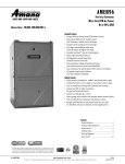
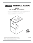
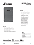
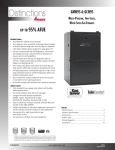
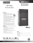
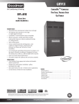
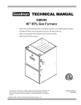
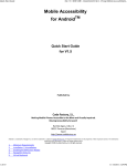
GME95 ® Two-Stage Convertible, Multi-Speed ECM Gas Furnaces Up to 96% AFUE ® Heating Input: 40,000–100,000 BTU/h Standard Features • Energy-efficient multi-speed ECM blower motor • Heavy-duty aluminized-steel dualdiameter, tubular heat exchanger • Stainless-steel secondary heat exchanger • Two-stage convertible gas valve automatically adjust to high or low stage • Durable Silicon Nitride igniter • Quiet single speed draft inducer • Self-diagnostic control board with constant memory fault code • Color-coded low-voltage terminals with provisions for electronic air cleaner and humidifier • Low continuous fan speed options offer quiet air circulation • All models comply with California Low NOx emissions standards Cabinet Features • Multi-position installation: upflow, horizontal left or right • Certified for direct vent (2-pipe) or non-direct vent (1-pipe) • Easy to install top venting with optional side venting • Convenient left or right connection for gas and electrical service • Cabinet air leakage (QLeak) ≤ 2% • Heavy-gauge steel cabinet with durable baked-enamel finish • Fully insulated heat exchanger and blower section • Airtight solid bottom or side-return with easy-cut tabs for effortless removal in bottom air-inlet applications Contents Nomenclature........................................ 2 Product Specifications........................... 3 Dimensions............................................ 4 Airflow Data........................................... 5 Wiring Diagram.......................................7 Accessories............................................. 8 * Complete warranty details available from your local dealer or at www.amana-hac.com. To receive the Lifetime Heat Exchanger Limited Warranty (good for as long as you own your home), 10-Year Unit Replacement Limited Warranty and 10-Year Parts Limited Warranty, online registration must be completed within 60 days of installation. Online registration is not required in California or Québec. SS-DGME95 www.amana-hac.com Amana® is a trademark of Maytag Corporation or its related companies and used under license to Goodman Company, L.P., Houston, Texas. 5/14 Supersedes 11/12 Product Specifications Nomenclature G M E 95 040 4 B * ** 1 2 3 4,5 6,7,8 9 10 11 12,13 Brand G Goodman® Brand or Dis0nc0ons™ Revisions Major and Minor Revisions Airflow Direc2on C Downflow/Horizontal D Dedicated Downflow H High Airflow K Dedicated Upflow M Upflow/Horizontal NOx N Natural Gas X Low NOx Cabinet Width A 14” B 17½” C 21” D 24½” Descrip2on/Motor V Two-‐Stage/Variable-‐speed H Two-‐Stage/Mul0-‐speed S Single-‐Stage/Mul0-‐speed E Two-‐Stage/EEM Motor 3 1200 AFUE 95 95% 9 93%+ 8 80% 2 Maximum CFM @ 0.5” ESP 4 1600 5 2000 040: 40,000 060: 60,000 080: 80,000 www.amana-hac.com MBTU/h 100: 100,000 120: 120,000 SS-DGME95 Product Specifications Specifications GME95 0403BXA* GME95 0603BXA* GME95 0805CXA* GME95 1005DXA* 40,000 60,000 80,000 100,000 Heating Capacity Input¹ Natural Gas Output¹ 38,400 57,700 76,900 96,100 LP Gas Output¹ 38,400 57,700 76,900 96,100 96.1 96.1 96.1 96.1 3 3 5 5 15-45 30-60 30-60 35-65 Size (D x W) 10” x 8” 10” x 8” 10” x 10” 11” x 10” Horsepower ½ ½ 1 1 Speed 5 5 5 5 Vent Diameter³ 2” 2” 3” 3” AFUE² Available AC @ 0.5” ESP Temperature Rise Range (°F) Circulator Blower No. of Burners Disposable Filter Size (in²) 2 3 4 5 580 580 960 960 7.9 9.2 10.0 11.1 15 15 15 15 120 124 144 162 Electrical Data Min. Circuit Ampacity5 Max. Overcurrent Device (amps) Ship Weight (lbs) 6 ¹ Natural Gas BTU/h. For altitudes above 2,000’, reduce input rating 4% for each 1,000’ above sea level. Low-fire rate is 75% of high-fire rate ² DOE AFUE based upon Isolated Combustion System (ICS) ³ Vent and combustion air diameters may vary depending upon vent length. Refer to the latest editions of the National Fuel Gas Code NFPA 54/ANSI Z223.1 (in the USA) and the Canada National Standard of Canada, CAN/CSA B149.1 and CAN/CSA B142.2 (in Canada). ⁴ Permanent air filter size is based on 600 FPM velocity. Check with filter manufacturer for specific details. ⁵ Minimum Circuit Ampacity = (1.25 x Circulator Blower Amps) + ID Blower amps. Wire size should be determined in accordance with National Electrical Codes. Extensive wire runs will require larger wire sizes. ⁶ Maximum Overcurrent Protection Device refers to maximum recommended fuse or circuit breaker size. May use fuses or HACR-type circuit breakers of the same size as noted. Notes • All furnaces are manufactured for use on 115 VAC, 60 Hz, single-phase electrical supply. • Gas Service Connection ½” FPT • Important: Size fuses and wires properly and make electrical connections in accordance with the National Electrical Code and/or all existing local codes. SS-DGME95 www.amana-hac.com 3 Product Specifications Dimensions COMPONENT IDENTIFICATION GMH95*****XA* AIR DISCHARGE AIR DISCHARGE 19 7/8” AIR INTAKE PIPE 2" PVC RIGHT SIDE DRAIN LINE HOLES 1 1/2 2 1 5/8 1 UNFOLDED FLANGES UNFOLDED FLANGES FOLDED FLANGES FOLDED FLANGES RIGHT SIDE VIEW Model GME950403BXA* GME950603BXA* GME950805CXA* GME951005DXA* A 17½” Cabinet Size 17½” GMH950453BXA* 21” GMH950703BXA* 24½” B 16” A 16” 19½” 17-1/2 23” B 16 C 13⅛” C 13⅛” 16⅛” 12-15/16 20⅝” D 12-1/8 D 12⅛” E 12⅛” 16 13-5/8 19⅜” E 13⅝” 13⅝” 17½” 20⅞” Notes: GMH950704CXA* 17-1/2 16 19-1/2 15-15/16 21 • Installer must supply one or two PVCGMH950904CXA* pipes: one for combustion air (optional) and one for the flue outlet (required). Vent pipe must be either 2” or 3” in diameter, depending upon furnace input, number of elbows, length of run, and installation (1 or 2 pipes). The optional combustion air pipe is GMH950905DXA* dependent on installation/code requirements and must be 2” or 3” diameter PVC. 23 20-7/16 • Line voltage wiring can enter through the right or left side of24-1/2 furnace. Low-voltage wiring can enter19-3/8 through the20-7/8 right or left side of furnace. GMH951155DXA* • Conversion kits for high-altitude natural gas operation are available. Contact your Goodman distributor or dealer for details. • Installer must supply the following line fittings, Allgas dimensions are according in inches. to which entrance is used: Left: One 90º street elbow; one 2½” pipe nipple; one 90º elbow; straight pipe; one ground joint union Right: Straight pipe to reach gas valve • Installations using a bottom return: Failure to unfold duct flanges will reduce airflow area by approximately 18%. This could result in performance and noise issues. NOTE:to Airflow area will M beaterials reduced by approximately 18% if duct flanges are not unfolded. This could cause performance issues and Minimum Clearances Combustible noise issues. • • • • • 4 Position Sides Rear Front Bottom Flue Top Upflow 0” 0” 1” C 0” 1” Horizontal 6” 0” 1” C 0” 4” 6 on combustible floor, the floor MUST be wood ONLY. C = If placed For servicing or cleaning, a 24” front clearance is recommended. Unit connections (electrical, flue, and drain) may necessitate greater clearances than the minimum clearances listed above. In all cases, accessibility clearance must take precedence over clearances from the enclosure where accessibility clearances are greater. Approved for line contact in the horizontal position www.amana-hac.com SS-DGME95 Product Specifications Airflow Data (CFM & Temperature Rise vs. External Static Pressure) Model GME95 0403BXA* (MED-HI \ T4) GME95 0603BXA* (MED-HI \ T4) GME95 0805CXA* (MED-HI \ T4) GME95 1005DXA* (MED-HI \ T4) Motor Speed Tons AC ¹ External Static Pressure, (Inches Water Column) 0.1 0.2 0.3 CFM Rise CFM Rise CFM 0.4 Rise CFM 0.5 Rise CFM 0.6 0.7 0.8 Rise CFM CFM CFM T1 1.5 726 48 670 53 617 57 553 64 490 72 429 378 336 T2 2.0 905 39 860 41 812 43 761 46 712 49 663 610 574 T3 2.5 1,121 31 1,074 33 1,039 34 998 35 959 37 923 882 839 T4 3.0 1,274 28 1,239 28 1,199 29 1,166 30 1,129 31 1,096 1,059 1,021 T5 3.0 1,306 27 1,261 28 1,232 29 1,195 29 1,162 30 1,132 1,090 1,057 T1 1.5 714 80 667 79 604 87 548 96 484 109 422 367 325 T2 2.0 904 58 851 62 804 66 761 69 708 75 664 612 572 T3 2.5 1,125 47 1,075 49 1,045 51 999 53 956 55 921 877 839 T4 3.0 1,312 40 1,271 42 1,228 43 1,202 44 1,165 45 1,127 1,087 1,044 T5 3.5 1,423 37 1,386 38 1,354 39 1,321 40 1,278 41 1,210 1,134 1,032 T1 3.0 1,297 54 1,253 56 1,209 58 1,161 61 1,111 63 1,067 1,022 974 T2 3.5 1,507 47 1,455 48 1,422 49 1,377 51 1,334 53 1,296 1,251 1,195 T3 4.0 1,677 42 1,637 43 1,602 44 1,562 45 1,526 46 1,484 1,441 1,324 T4 4.0 1,879 37 1,842 38 1,800 39 1,762 40 1,700 41 1,566 1,437 1,319 T5 5.0 2,044 35 1,967 36 1,894 37 1,795 39 1,702 41 1,578 1,452 1,320 T1 3.0 1,331 66 1,275 69 1,206 73 1,145 77 1,080 81 1,021 953 889 T2 3.5 1,512 58 1,452 60 1,392 63 1,336 66 1,279 69 1,219 1,175 1,115 T3 4.0 1,713 51 1,666 53 1,614 57 1,569 56 1,513 58 1,468 1,414 1,364 T4 4.0 1,892 46 1,845 48 1,802 49 1,752 50 1,707 52 1,656 1,614 1,577 T5 5.0 2,080 42 2,038 43 2,005 44 1,960 45 1,920 46 1,879 1,843 1,791 ¹ @0.5” ESP Notes • CFM in chart is without filter(s). Filters do not ship with this furnace, but must be provided by the installer. • All furnaces ship as high-speed cooling and medium-speed heating. Installer must adjust blower cooling & heating speed as needed. • For most applications, about 400 CFM per ton when cooling is desirable. • INSTALLATION IS TO BE ADJUSTED TO OBTAIN TEMPERATURE RISE WITHIN THE RANGE SPECIFIED ON THE RATING PLATE. • The chart is for information only. For satisfactory operation, external static pressure should not exceed value shown on the rating plate. • The above chart is for furnaces installed at 0-2000 feet. At higher altitudes, a properly de-rated unit will have approximately the same temperature rise at a particular CFM, while ESP at the CFM will be lower. SS-DGME95 www.amana-hac.com 5 6 www.amana-hac.com 10 20 30 40 50 60 70 30 80 90 100 40 50 60 700 600 CFM 90 100 2000 2200 2400 CFM 1800 1600 1400 OUTPUT BTU/HR x 1000 Output BTU/h x 1,000 80 1200 1100 1000 900 70 800 Formulas FORMULAS 110 120 130 CFM x 1.08 140 BTUBTU/h OUTPUT RISE Output==CFM CFRMxx 1.08 1.08 xxRise BTU OUTPUT RISE = = BTU/H Output ÷÷ CFM Rise CFM 1.08 BTU OUTPUT vs TEMPERATURE CHART BTU/h Output Vs. TemperatureRISE Rise Chart 150 Product Specifications Temperature Rise Chart SS-DGME95 TEMPERATURE RISE Temperature Rise E D C B 6.00 ±.10 LABEL Product Specifications 5.50 ±.10 FRAME Wiring Diagram 8 BK BK 2 1 5 4 9 8 7 BL MODE 12 11 10 YL GY HEAT OFF DELAY FACTORY SETTINGS SHOWN FS 2 1 115 VAC HOT AND PARK TERMINALS R WH RO1 (5) MANUAL RESET ROLLOUT LIMIT CONTROL(S) (SINGLE CONTROL ON 45K BTU) 24 VAC TH (3) 115 VAC FS 6 BL GY OR HE LO AT -H BR WH OR COOL-H CIRCULATOR BLWR HI -H AT HE ELECTRONIC AIR CLEANER LINE-H MANUAL RESET AUXILIARY LIMITS (1) IN UPFLOW BLOWER DECK GND 10.75 ±.10 LABEL BK WH JUNCTION BOX DOOR SWITCH WH INDUCED DRAFT BLOWER W ARNING : DISCONNECT POWER BEFORE SERVICING. WIRING TO UNIT MUST BE PROPERLY POLARIZED AND GROUNDED. WH A UTO R ESET P RIM A RY LIM IT C O NTR OL PU BL YL C PK FLAME SENSOR DISCONNECT 2 2 FLASHES = PRESSURE SWITCH STUCK CLOSED HI VOLTAGE (115V) HI VOLTAGE FIELD 6 6 FLASHES = OPEN RO LLO UT OR O PEN FUSE C CONTINUOUS/RAPID FLASHES = REVERSED 115 VAC POLARITY PK PINK WH WHITE PU PURPLE GN GREEN BL BLUE BK BLACK RD RED GY GRAY IGNITER TERMINAL INTERNAL TO INTEGRATED CONTROL PLUG CONNECTION SWITCH (PRESS.) OVERCURRENT PROT. DEVICE www.amana-hac.com DESCRIPTION SS-DGME95 INITIAL RELEASE 0140F01115-A 2 NOTES: 1. SET HEAT ANTICIPATOR ON ROOM THERMOSTAT AT 0.7 AMPS. 2. MANUFACTURERS SPECIFIED REPLACEMENT PARTS MUST BE USED WHEN SERVICING. 3. IF ANY OF THE ORIGINAL WIRE AS SUPPLIED WITH THE FURNACE MUST BE REPLACED, IT MUST BE REPLACED WITH WIRING MATERIAL HAVING A TEMPERATURE RATING OF AT LEAST 105°C. USE COPPER CONDUCTORS ONLY. 4. BLOWER SPEEDS SHOULD BE ADJUSTED BY INSTALLER TO MATCH THE INSTALLATION REQUIREMENTS SO AS TO PROVIDE THE CORRECT HEATING TEMPERATURE RISE AND THE CORRECT CFM (SEE SPEC SHEET FOR AIR FLOW CHART). 5. UNIT MUST BE PERMANENTLY GROUNDED AND CONFORM TO N.E.C. AND LOCAL CODES. 6. TO RECALL THE LAST 5 FAULTS, MOST RECENT TO LEAST RECENT, DEPRESS SWITCH FOR MORE THAN 2 SECONDS WHILE IN STANDBY (NO THERMOSTAT INPUTS) A BR BROWN OR ORANGE SWITCH (TEMP.) REV ZONE COLOR CODES: YL YELLOW JUNCTION FIELD GND FIELD SPLICE ECN 7 FLASHES = LOW FLAME SIGNAL 8 FLASHES = CHECK IGNITER OR IMPROPER GROUNDING EQUIPMENT GND 1105970 7 8 LOW VOLTAGE (24V) LOW VOLTAGE FIELD 3 = CONTROL FAILURE = 5 FLASHES = FLAME SENSE WITHOUT GAS VALVE L BK OFF 5 N GND 1 FLASH 3 FLASHES = PRESSURE SWITCH STUCK OPEN WARNING:DISCONNECT POWER BEFORE SERVICING.WIRING TO UNIT MUST BE PROPERLY POLARIZED AND GROUNDED. WH 1 4 FLASHES = OPEN HIGH LIMIT N TO 115 VAC / 1Ø / 60HZ POWER SUPPLY WITH OVERCURRENT PROTECTION DEVICE JUNCTION BOX STEADY ON = NORMAL OPERATION 3 GND 4 BL 0 4 L RD M A NU AL R ESET R O LLO UT LIM IT C O N TR O L(S ) ID BLOWER ( SINGLE CONTROL ON 45K BTU ) 24 VAC PRESSURE HUMIDIFIER SWITCH FRONT COVER PRESSURE SWITCH NO C 2 CIRCUIT GY GY PM 1 CONNECTOR GR GND HOT 3 BR C SURFACE IGNITER OR 2 HI GAS VALVE (HONEYWELL) SYSTE M LOCKOU T (RETRIES EXCE EDED ) DISCONNECT TO 115VAC/ 1 Ø /60 HZ POWER SUPPLY WITH OVERCURRENT PROTECTION DEVICE OR WH 5 10.25 ±.10 FRAME EAC-H BURNER COMPARTMENT NO ID BLWR IND PU BLOWER COMPARTMENT OR HOT SURFACE IGNITER IGN INTEGRATED CONTROL MODULE LINE NEUTRALS OR WH BK CIRCULATOR BLOWER RD MANUAL RESET AUXILIARY AUTO RESET LIMIT CONTROL PRIMARY LIMIT CONTROL RO2 (11) FLAME SENSOR PK RD HLO (1) XFMR-H YL BK (HI) BL (MED HI) OR (MED) RD (MED LOW) YL (LOW) W WH GR RD WH NO C HLI (7) 40 VA TRANSFORMER BK LINE-H SEE NOTE 4 GND PS (10) PSO (4) TO MICRO INTEGRATED CONTROL MODULE HEAT-H COOL-H Y PK XFMR-H SEE NOTE 6 DIAGNOSTIC LED BR RD GY OR * GR OR OR 115 VAC NEUTRAL TERMINALS * * * OR G 7 ON OFF PK 3 6 INTEGRATED CONTROL MODULE GY 24V THERMOSTAT CONNECTIONS OR FUSE ⚡ WH BK 2ND STAGE DELAY PM ID BLOWER PRESSURE SWITCH MVH (12) C MVL(2) NO FRONT COVER PRESSURE SWITCH C W Y ⚠ Warning 115 VAC R G GAS HI VALVE C GND GND (8) MVC (9) 40 VA TRANSFORMER Wiring is subject to change. Always refer to the wiring diagram or the unit for the most up-to-date wiring. C INTEGRATED CONTROL MODULE HUMIDIFIER TR (6) High Voltage: Disconnect all power before servicing or installing this unit. Multiple power sources may be present. Failure to do so may cause property damage, personal injury, or death. GY 24 VAC 24V THERMOSTAT CONNECTIONS BLOWER COMPARTMENT DOOR SWITCH (OPEN WHEN DOOR OPEN) OR 24 VAC HUMIDIFIER 7 Product Specifications Accessories Accessory GME95 GME95 GME95 GME95 0403BXA* 0603BXA* 0805CXA* 1005DXA* Description LPM-06 LP Conversion Kit (Springs & Orifice) ¹ √ √ √ √ LPLP03 LP Gas Low-Pressure Kit √ √ √ √ GSAS Electronic Air Cleaners (-10, -11, -12, -18) √ √ √ √ GMU Media Air Cleaners (1620, 2020, 1625, 2025) √ √ √ √ EFR01 External Filter Rack √ √ √ √ DCVK-20 Horizontal/Vertical Concentric Vent Kit (2”) √ √ --- --- DCVK-30 Horizontal/Vertical Concentric Vent Kit (3”) √ √ √ √ 0170K00000S Flush-mount Vent Kit √ √ √ √ ¹ White-Rodgers and Honeywell valves √ Indicates accessories available for this model Note: All installations above 7,000’ require a pressure switch change. For installation in Canada, furnaces are certified only to 4,500’. Amana® is a trademark of Maytag Corporation or its related companies and used under license to Goodman Company, L.P. All rights reserved. Our continuing commitment to quality products may mean a change in specifications without notice. © 2014 • Goodman Company, L.P. • Houston, Texas • Printed in the USA. 8 www.amana-hac.com SS-DGME95