1
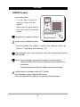
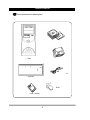
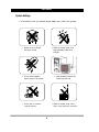
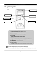
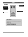
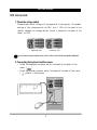
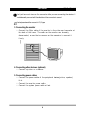
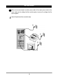
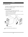
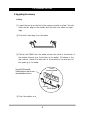
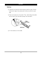
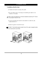
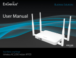
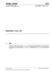
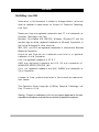
User's Manual
First Editing : June 1999
Information in this document is subject to change without notice and
does not represent a commitment on the part of Computer Technology
Link Corp.
Daewoo and logo are registered trademarks and CT is a trademarks of
Computer Technology Link Corp.
Microsoft, Drive Space, MS, MS-DOS, Windows, Windows NT, and the
windows logo are either registered trademarks of Microsoft Corporation in
the United States and/or other countries.
IBM, OS/2, and PS/2 are registered trademarks of International Business
Machines Corporation.
Overdrive and Pentium are trademarks and Intel is a registered
trademark of intel Corporation.
Unix is a registered trademark of AT & T.
AMD are registered trademark and K5, K6 are trademarks of
ADVANCED MICRO DEVICES, INC
Cyrix is a registered trademark and 6x86, 6x86MX are trademarks of
Cyrix Corporation.
Licenses for other products mentioned in this manual are reserved by
their owners.
This Operator's Guide is copyright Ⓒ 1999 by Computer Technology Link
Corp. Printed in U.S.A.
Warning : Changes or modifications to this unit not expressly approved by the party
responsible for compliance could void the user's authority to operate the equipment.
Table of Content
Table of Content
Starting--------------------------------------------------------------------------------------------------- 2
DAEWOO Computer--------------------------------------------------------- 2
Check Items------------------------------------------------------------------ 3
System Setting--------------------------------------------------------------- 4
Ch1. System Configuration---------------------------------------------------------------------- 5
Front Pannel----------------------------------------------------------------- 5
Back Pannel ----------------------------------------------------------------- 6
Ch2. Start to Install----------------------------------------------------------------------------------- 7
1.
2.
3.
4.
5.
Check the voltage switch-----------------------------------------------Connecting the keyboard and mouse ----------------------------------Connecting the monitor-------------------------------------------------Connecting the other devices-------------------------------------------Connecting the power cables--------------------------------------------
7
7
8
8
8
Ch3. Upgrading the system--------------------------------------------------------------------10
1. How to open the chassis------------------------------------------------ 10
2. Upgrading the memory------------------------------------------------- 11
3. Installation of the add-on cards --------------------------------------- 13
User's Manual
DAEWOO Computer
How to use this manual
◈ It is very easy to install the
computer system with this
manual.
Please read this guide carefully,
before you install the computer
system.
is a sign that you should pay an attention.
is a sign of recommendable information.
◈ Before upgrading your system or replacing any hardware, please read
Chapter 3 "Upgrading and Replacing" first.
Before opening the system chasis, remember to turn off the system and to disconnect all
cords and cables.
Caution : There is the danger of an explosion if the battery is incorrectly replaced.
Replace the battery with the same or equivalent type recommended by the
manufacturer.
Discard used batteries according to the battery manufacturer's instructions.
The lithum battery in mainboard is used for the RTC backup.
When the battery is used up, change another new one.
Refer to the main board user's guide, when you exchange the external battery.
2
DAEWOO COMPUTER
Check your boxes for the following items
◈ CD-ROM Title
◈ Tower
◈ Installation Diskette
◈ Power Cord
◈ Keyboard
◈ Mouse
◈ User's manual
3
User's Manual
System Settings
◈ Information that you should know before you intall the system.
▲ Please do not overload
the power socket.
▲ Place the system away from
high temperature and direct
sunlight.
▲ Do not place magnetic
objects close to the system.
▲ Keep distance between the
system and the wall.
▲ Avoid dust or moisture
from the system.
▲ Place the system away from a
radio or any electronic receivers.
4
CH1. SYSTEM CONFIGURATION
CH1. System configuration
Front
5. CD-ROM Drive
6. Floppy Disk Drive
2. H/W Reset Button
3. Power LED
4. HDD LED
1. Systom On/Off Button
1. System On/Off Button
To turn on and to turn off the computer system.
2. H/W Reset Button
This button initializes and restarts the computer.
3. Power LED
The light that indicates the system is working.
4. HDD LED
The light that indicates the system is accessing the Hard Disk Drive.
5. CD-ROM Drive
The drive that can read CD-ROM titles.
6. Floppy Disk Drive
3.5" Floppy Disk Drive that can read a data from, or write a data to.
The system configuration can be changed to the Main board.
If the system configuration is different to the figure, refer to the Main board user's manual.
5
User's Manual
CH1. System configuration
Back Pannel
3. Input Power Socket
2. Input Power Slect Switch
1. Output Power Socket
4. Video Card Connector for Monitor
Refer to B’d Manual
1. SMPS On/Off Switch
The switch that enables or disables the SMPS.
2. Input Power Select Switch
Two different voltages, 115V and 230V, can be selected with this switch.
3. Input Power Socket
The socket that supports power to the tower.
4. Video Card Connector for Monitor
A monitor can be used through this connector.
6
CH2. START TO INSTALL
CH2. Start to install
1. Check the voltage switch
Please check which voltage will be supported to the system. The default
setting of the voltage switch is 230V, but if 115V will be used in the
system, change the voltage switch, which is located at the back of the
tower, to 115V.
▲ default mode : 230V
▲ other mode : 115V
Do not connect power cables to the system until you finish all the described installateion.
2. Connecting the keyboard and the mouse
◎ Check the keyboard connector which is located at the back of the
tower. (
)
◎ Check the mouse connector which is located at the back of the tower.
(
)(Refer to the picture)
7
User's Manual
CH2. Start To Install
Don't put too much force on the connector while you are connecting the devices. It
would be easily connected if the direction of the connector is correct.
The keyboard and the mouse is in PS/2 type.
3. Connecting the monitor
◎ Connect the 15pin cable of the monitor to the video card connector at
the back of the tower. The cable on the monitor can be easily
disconnected, so use the two screws on the connector to connect it
firmly.
4. Connecting other devices. (optional)
◎ Connect a printer or a scanner.
5. Connecting power cables
◎ Connect the power cables of the peripheral devices(printer, speaker)
first.
◎ Connect the monitor power cable.
◎ Connect the system power cable at last.
8
CH2. START TO INSTALL
While you are connecting the monitor power cable to the output power socket of the
tower, make sure the voltage that the monitor requires is same as the voltage that the
system supports.
Refer to the picture for the connection steps.
③
①
②
9
User's Manual
CH3. Upgrading the system:
The system can be damaged if any device is removed or added while the
power cable is still connected. Remember to disconnect the power cable
before you start upgrading the system.
1. How to open the chassis
◎
◎
◎
◎
◎
◎
Turn the system off and disconnect the power cable.
Turn off all the peripheral devices that are connected to the system.
Disconnect all the cables from the system.
Disconnect the mouse and the keyboard.
Pull the front cover out and lift it up.
Unscrew the two screws, one at the front and the other at the back of
the tower.
unscrew here
(refer to the picture).
② Up
② Lift up
① Pull
① Push the bottom of the cover
Follow the above step from the last to re-build the system.
10
CH3. UPGRADING THE SYSTEM
2. Upgrading the memory:
Installing
① Locate the two clips that hold the memory moudle in place. One clip
holds the left edge of the moudle and the other clip holds the right
dege.
② Push both clips away from the socket.
③ Position the DIMM over the socket so that the notch at the bottom of
the module lines up over the divider in the socket. AS shown in the
next picture, match the wide part of the module to the wide part of
the opening in the socket.
DIMM
memory module
To insert DIMM module:
Position bottom notches over
socket dividers as shown.
notches
DIMM Socket
④ Push the module streight down into the socket.
11
User's Manual
Replacing:
① Locate the two clips that hold the memory module in place. One clip
holds the left edge of the module and the other clip holds the right
edge.
② Push one clip away from the module. Then, while holding the module
with one hand, push the other clip away from the module.
③ Lift the module out of the socket.
12
CH3. UPGRADING THE SYSTEM
3. Installation of Add-On Cards
① Unscrew and remove an empty slot guide.
② Put an Add-On Card in the empty slot carefully.(be careful to the
direction of the card)
Add-On Cards can be placed in any of the slots, but please be careful to put PCI Cards in
PCI slots, and put ISA cards in ISA slots.
③ If there are cables that should be connected to the Add-On card,
please connect to it.
④ Screw the guide of the Add-On card.
The Add-On Card should be properly inserted in the slot. If the card is not properly inserted,
then it could cause the system failure.
13