1
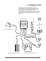
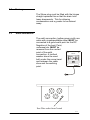
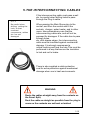
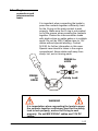
USER GUIDE
SHORE POWER SYSTEM
230 VAC
2 30 VAC
FU SE
HOT W:
CHARG ER
Disclaimer
Nord West Marine provides this publication as is without warranty of any kind,
either express or implied, including but not limited to the implied warranties of
merchantability or fitness for any particular purpose. Further, N.W.M.
reserves the right to revise this publication and to make changes from time to
time to the content hereof, without obligation to N.W.M. its local
representatives to notify any person of such revision or changes. Some
jurisdictions do not allow disclaimers of expressed or implied warranties in
certain transactions; therefore, this statement may not apply to you.
Limited Warranty
N.W.M. warrants that the Shore Power System will substantially conform to
published specifications and to the documentation, provided that it is used for
the purpose for which it was designed. N.W.M. will, for a period of twelve
(12) months from date of purchase, replace or repair any defective system, if the
fault is due to a manufacturing defect. In no event will N.W.M. or its local
representatives be liable for direct, indirect, special, incidental, or consequential
damages arising out of the use of or inability to use the Shore Power System,
even if advised of the possibility of such damages. N.W.M. or its local
representatives are not responsible for any costs, loss of profits, loss of data, or
claims by third parties due to use of, or inability to use the Shore Power System.
Neither N.W.M. nor its local representatives will accept, nor be bound by
any other form of guarantee concerning the Shore Power System other than this
guarantee. Some jurisdictions do not allow disclaimers of expressed or implied
warranties in certain transactions; therefore, this statement may not apply to
you.
Document version 1.00
1-2
INDEX
1. INTRODUCTION...........................................................................................1-4
2. THE CENTRAL.............................................................................................2-5
3. SHORE MAINS PLUGG ...............................................................................3-6
3.1
3.2
3.3
Recessing the SHORE MAINS PLUG.................................................................................. 3-6
Drainage ................................................................................................................................. 3-7
Earth connection. ................................................................................................................... 3-7
4.1
4.2
4.3
Types of Sockets .................................................................................................................... 3-8
Mounting of Sockets for hided interconnecting cables ......................................................... 3-9
Sockets in Bath Rooms .......................................................................................................... 3-9
5.1
5.2
Making holes for cables....................................................................................................... 5-11
Plug-In connectors and interconnection leads..................................................................... 5-12
6.1
Mounting of
4. THE 230VAC SOCKETS ...............................................................................3-8
5. THE INTERCONNECTING CABLES ......................................................5-10
6. BATTERY CHARGER ................................................................................6-13
battery charger ......................................................................................... 6-13
7. ELEKTRONICAL WASTE (WEEE) .........................................................7-14
8. CLAIMS.........................................................................................................8-16
1-3
1. INTRODUCTION
The boat builder/ workshop is always
responsible for taking all necessary safety
precautions when installing a Shore
Power System. Make sure that the installation
is in accordance with the IP level on your
system.
230VAC Central
230 VAC
2 30 VAC
FUSE
HOT W:
CHARG ER
expandable
system
Shore Mains Plugg
Smart Split
Charger, Switch in Central
Hot Water, Switch in Central
1-4
2. THE CENTRAL
NOTE
The distance
between the shore
plug and 230V
central can at
maximum be 3m.
We offer
different cable
length up to 3m.
Check your system
for shore plug cable
length before you
drill holes/ make
recess for the
central and shore
plug.
Install the 230VAC Central in a suitable
location. You may use the enclosed template
for marking the recess hole.
The 230V central shall NOT
be installed in following
positions:
230 VAC
2 30 VAC
FU SE
HOT W:
upside-down or angled
•
close to 12V DC
distribution panels
•
open on a side wall
•
close to heaters or warm
objects
•
close to waste water
•
or mounted in such a way that the central
is easily exposed for physical damage with
danger as hazard
WARNING
The 230VAC central must be mounted so that it cant
be opened or hard braking as this constitute a safety
hazard
WARNING
Make sure that screws or drill bits do not damage
cables or control units on the back of the panel/wall
where the 230VAC central is fitted
3.
CHARG ER
•
3-5
SHORE MAINS PLUGG
NOTE
Make sure there is
sufficient space in
the rear for the
cable and enough
room for the
fastening nuts
3.1
The Shore Plug should be
mounted in such a way that it is protected
against rain, splash and mechanical damage,
and so that the connector lead can be
connected without difficulty.
If the surface is
uneven the attached
gasket may be to thin
to create a waterproof
connection. If so, use
a extra gasket or
foam as Sikaflex
marinegrade to seal
the joint.
Recessing the
SHORE MAINS
PLUG
NOTE
Be careful when
drilling/ cutting the
hole, so that
mounted
components, cables
etc. are not
damaged
The gasket may be used as a template for
cutting the hole for the shore plug.
Place the gasket carefully where you want to
mount the mains plug. Use a pencil and draw
a picture of the gasket.
Make the hole for recessing the shore mains
plug.
The SHORE MAIN plug shall be mounted so
that the cover is hinged horizontal.
The plug must not be fitted with the cover
hinge pointing downwards.
3-6
3.2
Drainage
The Shore plug must be fitted with the hinges
straight upwards this so that the drain hole
leans downwards. This for allowing
condensation and e.g water to be drained
away.
3.3
Earth connection.
The earth connection (yellow-green-multi core
cable with ringshapedcable shoe) MUST be
connected to a good earth point on the DC
Negative of the boat. Paint,
underseal etc. MUST be
removed from the contact
point of the earth
230 VAC
connection. A toothed
washer shoud be used
both under the screw head
and between the cable
shoe and the earthing
point.
2 30 VAC
Eart Wire outlet from Central
FU SE
HOT W:
CHARG ER
3-7
4. THE 230VAC SOCKETS
The 230VAC sockets must be placed in
accordance with the harmonized standards for
the market the boat is going to be sold /used
in.
4.1
Types of Sockets
The standard Shore
Power Sockets comes in IP
class 40 and 44. Please check
your supplied sockets and
make sure that they are as
ordered and suit your aria of
use. Please contact local
autorities if you are unsure
about your local IP
requirements.
For the Scandinavian marked,
the Sockets of IP class 40 is
intended for use in dry areas
as saloon and cabins. Please note that if you
have a boat with sun roof, the cabin can not
be clasified as dry.
The Sockets marked IP 44 are ‘splash proof’
and can be usen in the engineroom, kitchen
area, and can be used in bath room if its
protected against direct water jet from shower.
WARNING
The 230VAC sockets must be mounted so that its
protected against splash or water jet and any type of
mecanical damage with danger or hardbreak as reult.
Do no open or brak as this constitute a safety hazard
3-8
4.2
Mounting of
Sockets for hided
interconnecting
cables
NOTE
Be careful when
drilling/ cutting the
hole, so that
mounted
components, cables
etc. are not
damaged
NOTE
Make sure there is
minimum 5cm space
behind the Socket
for models with
cable mounted with
direction straight
back.
4.3
The standard shore sockets comes
in IP class 40 and 44.
Please check your supplied
sockets and make sure
that they are as ordered.
Recess the hole for the
socket carfully. Please
make sure that the space
behing the socket is
sufficient for the cable
Avoid bending the cable to
much. Minimum clerance
to Socket back is 5cm.
Sockets in Bath
Rooms
Before mounting Sockets in Bathroom make
sure that you have your Local regulations
available. For installations in boats for the
Norwegian market you shall mount the socket
60cm or more away from the shower cabinet,
if you want to mount the socket lower than
170cm from the floor.
WARNING
The 230VAC sockets must be mounted so that its
protected against water from the shower.
3-9
5.THE INTERCONNECTING CABLES
If the interconnecting cable must pass a wall
etc, be careful when drilling holes to pass
through the Plug-In cable.
NOTE
Be careful when
drilling/ cutting the
hole, so that
mounted
components, cables
etc. are not
damaged
When passing the Main Shore plug to the
central, and from the central and to the
sockets, charger, water heater, and to other
users. take extraordinary care that the
interconnecting cables are, and will not be,
exposed for damages. If the cable has to pass
through holes,
etc, with sharpe edges, the interconnecting
cable must be insulated against mechanical
damage. It is strongly recommend a
rubber bushing and seal the hole This must be
performed in a way that secure the insulation
to last and not to brake.
There is also supplied a cable protection
coat for extra protection against mechanical
damage when use in hash environments.
WARNING
Route the cables straight away from the contacts on
the Smart Split,
Rout the cable as streight as possible from the plug in
users so the contacts are not bent or twisted
5-10
5.1
Making holes for
cables
A Ø25mm hole saw is a particularly suitable
tool for this task. Make sure that the tool does
not damage fitted
components, brake lines,
electrical cables etc.
To seal the holes and to
protect against
mecanical damage use
e.g a rubber bushing to
seal the hole. Make sure
the rubber bushing is
fitted properly.
1
Interconnecting cables
should slope downwards
from the passing through
point into the cabin
compartment (1) so that
water or humidity does not run along the cable
into the cabin.
If passing through dirty arias clean the
surfaces carefully with a suitable grease
solvent, for instance Acrysol. Do not use
acetone, trichlorethylene, Breakclean or
similar products as PVC and plastic may be
damaged.
5-11
5.2
Plug-In
connectors and
interconnection
leads.
It is important when connecting the leads to
press the contacts together sufficiently hard
for the O-ring on the male contact to seal
properly. Make sure the O-ring is not pushed
out of the groove when pressing the contacts
together. Fasten the interconnection leads
with plastic strips on cable gates or in suitable
spots. Do not lay 230V Cables close to 12V
cables without special labelling. Contact
N.W.M. for further information in this case.
Special care should to taken in the engine
compartment. Keep cables well away from
sharp, hot, wet or moving parts.
PRESS to
LOCK
PRESS
to
OPEN
Safety Lock
WARNING
It is importation when connecting the leads to press
the contacts together sufficiency hard for the safety
lock to lock properly, and so the O-ring to seal
properly. Do not MIX 230VAC cables and 12V DC
cables
5-12
6. BATTERY CHARGER
When use of a charger not supplied from
N.W.M, nor equipped with N.W.M.’s special
safe plug in connectors, connection the battery
charger via a standard shore Power
socket as shown from the manufacturers
wiring diagram.
Connect the battery charger in accordance
with the diagram attached with the charger.
All other connections will be treated as illegal.
In such case the system safety and system
warranty in not valid.
6.1
Mounting of
battery charger
NOTE
Avoid charging
batteries in a closed
area, as there is a
potential danger of
explosion.
Mount the battery charger in accordance with
the attached battery chargers user guide.
Make sure the battery charger is not placed
too close to hot parts such as engine or
engine exhaust pipes.
READ battery
charger User Guid
before mounting.
For connections from the Battery Charger to
the Battery, always read the Battery Chargers
User Manual Carefully
Connection to the
battery must always
be made with the
enclosed fuse.
For Retronic Chargers, see specific Battery
Charger Mounting Instruction.
6-13
WARNING
The temperature of the battery may not exceed
+40ºC during charging.
WARNING
The charger contains high voltage current. Therefore
do not use a drill on it or open it.
7. Elektronical Waste (WEEE)
The use of WEEE
symbol indicates that
this product can NOT
be treated as ordinary
household waste.
To protect the
environment make sure
that this product is not
delivered through a
ordinary bin
If you are unsure, please contact your local
authorities for guidance regarding special
waste and recirculation of this type of product.
7-14
Technical Spesifications
Central /(Standard):
16A Dual Fused 30mA RCB
2 16A Switch ON/OFF circuits
Standard text: Hot Water-Charger
Other text on request
Number of circuits, functions etc. on request
WE CUSTOMIZE ALL ON REQUEST
Cables:
1,5mm2 and 2,5mm2
With or without extra protections
Standard: 1-2-3-4-5-7 m length
Other on request
Sockets:
Standard Scandinavian model
Standard IP 40 and 44
Others on request
Single, Dual and Combined 12/230
All types on request
All country models on request
Main Inlet Plug/ Cable
Stainless Steel
Waterproof IP67
16A/ 2,5mm2, Yellow-Marinegrade
25m with interface cable to Scandinavian output
feed.
Thank you for using Nord West Marine as SHORE POWER SYSTEM
7-15
8. Claims
Claims may not be made for damage resulting from:
Normal wear and tear
Faulty installation
Lack of maintenance and faulty or irresponsible
use
The use of non-original connectors/leads or use
together with non-original parts
Modification or repairs of the product, or attempts
thereon, carried out by others than N.W.M.
without written authorization by N.W.M to
carry out such modification, or repair conditions
after delivery beyond the control of N.W.M.
8-16


![Instrucciones Manipulación / Handling Instructions [ GENERAL ]](http://vs1.manualzilla.com/store/data/006270185_1-23c4fc4371ee2eaf6e3051f14a7d6232-150x150.png)