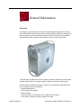
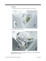
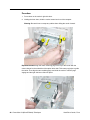
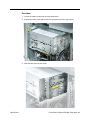
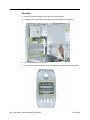
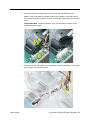
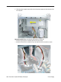
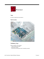
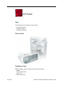
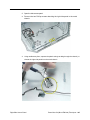
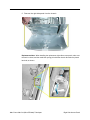
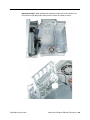
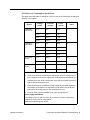
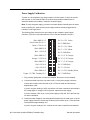
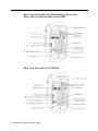
1
Service Source Power Mac G4 (Mirrored Drive Doors) Power Mac G4 (FW 800) Updated 22 February 2006 © 2003 Apple Computer, Inc. All rights reserved. Service Source Take Apart Power Mac G4 (Mirrored Drive Doors) Power Mac G4 (FW 800) © 2003 Apple Computer, Inc. All rights reserved. General Information Overview The identifying characteristics on the front of the Power Mac G4 (Mirrored Drive Doors), Power Mac G4 (Mirrored Drive Doors 2003), and Power Mac G4 (FW 800) computers are their top speaker and mirrored optical drive bezel. Like the Power Mac G4 (QuickSilver and QuickSilver 2002) computers, these models also have a silver-colored case. The Power Mac G4 (Mirrored Drive Doors 2003) computer is identical to the Power Mac G4 (Mirrored Drive Doors) computer except for updates to the drives and processor. The Power Mac G4 (FW 800) computer is similar to the Power Mac G4 (Mirrored Drive Doors) computer with these exceptions: • FireWire 800 Mbps port • AirPort Extreme Card option • Bluetooth option • SCSI card option is a third-party card; no Apple SCSI card option • SCSI cable is a third-party cable; no Apple SCSI cable General Information Power Mac G4 (Mirror/FW 800) Take Apart - 1 Important: The Take Apart procedures are the same for all versions of the computers unless model differences are noted. Tools The following tools are required: • #2 Phillips screwdriver • #1 Phillips screwdriver • T-10 Torx driver or 2.5 mm Allen wrench • Small flat-blade screwdriver • Needlenose pliers Note: Magnetized tools are recommended to avoid dropping screws within the computer. Note: To organize the screws you remove from the computer, use a tray with divided compartments (such as a plastic ice cube tray). Serial Number Location The computer’s serial number is located on the back panel. Before Opening the Computer Warning: The power supply in this computer is a high-voltage component and should not be opened for any reason, even when the computer is off. Warning: After shutting down the computer, you must wait a few minutes before servicing it to allow internal components to cool. Important: The only way to shut off power completely to the computer and display is to disconnect their power plugs from the power source. Make sure the power cords to the computer and display are within easy reach. Electrostatic Discharge (ESD) Precautions Follow these steps to avoid damage from ESD before working inside the computer. 1. Shut down the computer. 2. Wait a few minutes to allow the computer’s internal components to cool. 3. Unplug all cables from the computer except the power cord. 4. Touch the metal PCI access covers on the back panel to discharge static electricity. 5. Unplug the power cord. 6. Lift the latch on the side of the computer. (If the latch will not lift, check that the security lock port and lockable cover latch in the back of the computer are not locked.) 2 - Power Mac G4 (Mirror/FW 800) Take Apart General Information 7. Put on an ESD wrist strap. 8. To avoid static electricity building back up in your body, do not walk around the room until after you have finished working and closed the computer. Operating the Computer Warning: In this computer the lower fan is in direct line with the heatsink. However, when the computer is open and the side panel is set down, the fan and heatsink are no longer in contact. To avoid overheating and permanent damage, never turn on the computer unless all of its internal and external parts are in place and it is closed. Operating the computer when it is open or missing parts can damage the computer or cause injury. General Information Power Mac G4 (Mirror/FW 800) Take Apart - 3 Opening the Computer Tools No tools are required for this procedure. Preliminary Steps No preliminary steps are required before you begin this procedure. Procedure 1. Lift the latch to unlock the right side access panel. 2. Note: Gently lower the side panel onto a clean, ESD-safe mat to avoid scratching the case. Lower the side panel until it lies flat. Note: Release the latch before returning the side panel to its upright closed position. 4 - Power Mac G4 (Mirror/FW 800) Take Apart Opening the Computer Top Handles Tools The only tool required for this procedure is a 2.5 mm Allen wrench. Part Location Preliminary Steps There are no preliminary steps for this procedure. Top Handles Power Mac G4 (Mirror/FW 800) Take Apart - 5 Procedure 1. Remove the two Allen screws that secure the handle you are replacing. 2. Lift the handle from the computer. Replacement Note: When replacing a handle, make sure the inner prongs fit inside the raised points on the computer. 6 - Power Mac G4 (Mirror/FW 800) Take Apart Top Handles Replacement Note: When replacing a handle, make sure you orient the handle so the three tiny bumps are near the lower edge of the handle.The handle won’t fit properly if it is turned upside down. The top front and top rear handles are interchangeable. Top Handles Power Mac G4 (Mirror/FW 800) Take Apart - 7 Top Panel Tools No tools are required for this procedure. Part Location Preliminary Steps Before you begin, remove the handles from the top front and top rear of the computer. 8 - Power Mac G4 (Mirror/FW 800) Take Apart Top Panel Procedure 1. Slide the top panel toward the front of the computer to unhook the six tabs. 2. Lift the top panel from the chassis. Top Panel Power Mac G4 (Mirror/FW 800) Take Apart - 9 Speaker Grill Tools The only tool required for this procedure is a small flat-blade screwdriver. Part Location Preliminary Steps There are no preliminary steps for this procedure. 10 - Power Mac G4 (Mirror/FW 800) Take Apart Speaker Grill Procedure 1. Insert the tip of a screwdriver into one of the openings in the speaker grill. Warning: To prevent damage to the speaker, do not insert the screwdriver too far. 2. Pry out the speaker grill. Replacement Note: Press the replacement speaker grill into the speaker opening. Speaker Grill Power Mac G4 (Mirror/FW 800) Take Apart - 11 Lower Supports Tools The only tool required for this procedure is a 2.5 mm Allen wrench. Part Location Preliminary Steps Before you begin, place the computer upside down on an ESD mat. Warning: When the computer is upside down or the lower supports are removed, the computer can be unstable. 12 - Power Mac G4 (Mirror/FW 800) Take Apart Lower Supports Procedure 1. With the computer upside down, remove the two Allen screws securing the support to the computer. 2. Remove the support from the computer. Lower Supports Power Mac G4 (Mirror/FW 800) Take Apart - 13 Lower Panel, Front Tools No tools are required for this procedure. Part Location Preliminary Steps Before you begin, remove the lower front support. Warning: When the computer is upside down or the lower support is removed, the computer can be unstable. 14 - Power Mac G4 (Mirror/FW 800) Take Apart Lower Panel, Front Procedure 1. Lift the lower front panel from the chassis. There are no screws holding this panel to the chassis; the front support holds it in place. 2. Important: Note the routing of the AirPort antenna cable. Carefully remove it from the notches in the lower front panel. Lower Panel, Front Power Mac G4 (Mirror/FW 800) Take Apart - 15 Lower Panel, Rear Tools No tools are required for this procedure. Part Location Preliminary Steps Before you begin, remove the lower rear support. Warning: When the computer is upside down or the lower support is removed, the computer can be unstable. 16 - Power Mac G4 (Mirror/FW 800) Take Apart Lower Panel, Rear Procedure Lift the lower rear panel from the chassis. There are no screws holding this panel to the chassis; the rear support holds it in place. Lower Panel, Rear Power Mac G4 (Mirror/FW 800) Take Apart - 17 Rear Vented Panel Tools The following tools are required for this procedure: • 2.5 mm Allen wrench • Flat-blade screwdriver Part Location Preliminary Steps Before you begin, remove the following: • Lower rear support • Lower rear panel • Top rear handle Warning: When the computer is upside down or the lower supports are removed, the computer can be unstable. 18 - Power Mac G4 (Mirror/FW 800) Take Apart Rear Vented Panel Procedure 1. With the computer positioned on its left side panel, remove the three Allen screws securing the rear vented panel to the computer. 2. Use a flat-blade screwdriver to pry out the tabs from the lower chassis. Rear Vented Panel Power Mac G4 (Mirror/FW 800) Take Apart - 19 3. Grasp the rear vented panel on both sides of the lockable cover latch, and forcefully pull off the rear vented panel. 20 - Power Mac G4 (Mirror/FW 800) Take Apart Rear Vented Panel Hard Drive Carrier, Back Tools The following tools are required for this procedure: • Magnetized #2 Phillips screwdriver. • Pliers Part Location Preliminary Steps Before you begin, open the side access panel. Hard Drive Carrier, Back Power Mac G4 (Mirror/FW 800) Take Apart - 21 Procedure 1. Using a Phillips screwdriver, remove the screw that attaches the carrier to the chassis. Note: On some production models, the screw is not present nor required. 2. Pull the left side lever forward, and slide the carrier up to release the mounting pegs on the back of the carrier from the chassis. 22 - Power Mac G4 (Mirror/FW 800) Take Apart Hard Drive Carrier, Back 3. Rotate the carrier back from the chassis far enough to reach the drive cables. Disconnect the hard drive data and power cables (P2 and P3) from the hard drive(s). Note: You might need to use pliers to grasp and disconnect the power cable connector(s). 4. Remove the carrier and drive(s) from the computer. Replacement Note: Connect the cables to the drives before installing the carrier. Hard Drive Carrier, Back Power Mac G4 (Mirror/FW 800) Take Apart - 23 Replacement Note: Be sure to align the mounting pegs on the back of the carrier with the notches in the chassis. Then press the carrier in and down until the pegs engage and the left side lever clicks into place. 24 - Power Mac G4 (Mirror/FW 800) Take Apart Hard Drive Carrier, Back Hard Drive Carrier, Front Tools The only tool required for this procedure is a magnetized Phillips screwdriver. Part Location Preliminary Steps Before you begin, open the side access panel. Hard Drive Carrier, Front Power Mac G4 (Mirror/FW 800) Take Apart - 25 Procedure 1. Press down on the carrier’s right side lever. 2. Holding the lever down, slide the carrier forward and out of the computer. Warning: Be careful not to scrape any cables when sliding the carrier forward. Replacement Note: Align the center mounting peg on the top of the carrier with the center channel on the underside of the optical drive shelf. This center peg helps to guide the carrier. Then align the two remaining pegs, and slide the carrier in until the pegs engage and the right side lever clicks into place. 26 - Power Mac G4 (Mirror/FW 800) Take Apart Hard Drive Carrier, Front Replacement Note: Before closing the side access panel, make sure the P4 and P5 power cable connectors are either attached to the hard drives or tucked inside the front hard drive carrier. Hard Drive Carrier, Front Power Mac G4 (Mirror/FW 800) Take Apart - 27 Hard Drive Tools The only tool required for this procedure is a Phillips screwdriver. Preliminary Steps Before you begin, do the following: • Open the side access panel. • Remove the hard drive carrier. Procedure 1. Remove the four mounting screws from the sides of the drive carrier. 2. Slide the drive forward out the front of the drive carrier. 28 - Power Mac G4 (Mirror/FW 800) Take Apart ATA 100 Hard Drive Cable Tools No tools are required for this procedure. Preliminary Steps Before you begin, do the following: • Open the side access panel. • Remove the back hard drive carrier. Procedure 1. Open the cable clamp at the bottom of the chassis. 2. Disconnect the ATA 100 cable from the connector at J34 on the logic board. Power Mac G4 (Mirror/FW 800) Take Apart - 29 Optical Drive Tools The only tool required for this procedure is a Phillips screwdriver. Part Location Preliminary Steps Before you begin, open the side access panel. 30 - Power Mac G4 (Mirror/FW 800) Take Apart Optical Drive Procedure 1. Loosen the captive screw near the front panel board. 2. Remove the lower screw that secures the optical drive carrier to the chassis. 3. Slide the back panel off the carrier. Optical Drive Power Mac G4 (Mirror/FW 800) Take Apart - 31 4. Slide the carrier back and rotate it so that you can reach the drive cables. 5. Disconnect the drive data and power cables (P6 and P7) from the back of the optical drive(s) and remove the carrier from the computer. 6. Remove the four mounting screws from the sides of the drive carrier. 7. Slide the drive forward out the front of the drive carrier. 32 - Power Mac G4 (Mirror/FW 800) Take Apart Optical Drive Replacement Note: Before sliding the carrier back onto the optical drive shelf, make sure the power cable bundle at the side panel is routed in the recessed channel. Optical Drive Power Mac G4 (Mirror/FW 800) Take Apart - 33 Replacement Note: When sliding the carrier back onto the optical drive shelf, make sure the latch on the underside of the carrier engages with the notch in the drive shelf. Replacement Note: Before sliding the rear panel back onto the carrier, make sure the top lip of the panel engages with the top edge of the drive carrier. Warning: Be careful not to pinch the power cable between the panel and the carrier. 34 - Power Mac G4 (Mirror/FW 800) Take Apart Optical Drive Optical Drive Cable Tools No tools are required for this procedure. Preliminary Steps Before you begin, do the following: • Open the side access panel. • Remove the front hard drive carrier. • Remove the optical drive carrier. Procedure 1. Peel up the optical drive cable from the double-sided tape on the optical drive shelf. Power Mac G4 (Mirror/FW 800) Take Apart - 35 2. Open the two cable clamps at the bottom of the chassis. 3. Disconnect the cable from the logic board and free the cable from the opening in the optical drive shelf. 36 - Power Mac G4 (Mirror/FW 800) Take Apart Optical Drive Cable Lower Fan Tools The only tool required for this procedure is a small flat-blade screwdriver. Part Location Preliminary Steps Before you begin, do the following: • Open the side access panel. • Remove the optical drive carrier. Power Mac G4 (Mirror/FW 800) Take Apart - 37 Procedure 1. Disconnect the ribbon cable from the logic board and fold it back to expose the lower fan cable connector. 2. Using a small flat-blade screwdriver, gently lift up the locking tab on the lower fan cable and disconnect the cable from the logic board. Replacement Note: Route the fan cable under the ribbon cable and over the narrower flex cable, as shown. 38 - Power Mac G4 (Mirror/FW 800) Take Apart Lower Fan 3. Slide the fan straight up to disconnect it from the optical drive shelf, and remove the fan from the computer. Replacement Note: Align the fan with the three latches in the drive shelf and slide straight down until you feel the fan lock into place. Lower Fan Power Mac G4 (Mirror/FW 800) Take Apart - 39 Replacement Note: On some production models, the fan includes a detachable finger guard. To transfer the finger guard to the replacement fan, use a needlenose pliers to remove the four plastic pegs. Then transfer the finger guard to the replacement fan. 40 - Power Mac G4 (Mirror/FW 800) Take Apart Lower Fan Left Side Panel Tools The following tools are required for this procedure: • 2.5 mm Allen wrench • Needlenose pliers Part Location Preliminary Steps Before you begin, open the computer and remove the optical drive carrier. Left Side Panel Power Mac G4 (Mirror/FW 800) Take Apart - 41 Procedure 1. Remove the four 2.5 mm Allen screws on the side panel. 2. Using a needlenose pliers, squeeze the tabs (located beside the power supply cable bundle) to release the left side panel from the metal chassis. 3. Lift the left side panel from the chassis. 42 - Power Mac G4 (Mirror/FW 800) Take Apart Left Side Panel Front Panel Tools No tools are required for this procedure. Part Location Before you begin, open the computer and remove the following. • Handle at the top front of the computer • Support at the lower front of the computer • Speaker grill (if present) • Optical drive carrier Warning: When the lower support is removed, the computer can be unstable. Front Panel Power Mac G4 (Mirror/FW 800) Take Apart - 43 Procedure 1. Open the side access panel. Locate the four front panel tabs. 2. Carefully push the front panel tabs inward to release them from the chassis. 3. Pull the front panel off the chassis. 4. Press inward on the four tabs to remove the optical drive bezel from the front panel. 44 - Power Mac G4 (Mirror/FW 800) Take Apart Front Panel Power Supply Tools The following tools are required for this procedure: • #2 Phillips screwdriver • T-10 Torx driver Part Location Preliminary Steps Before you begin, do the following: • Open the side access panel. • Remove the optical drive carrier. • Remove the lower fan. Power Mac G4 (Mirror/FW 800) Take Apart - 45 Procedure Warning: The power supply in this computer is a high-voltage component and should not be opened for any reason, even when the computer is off. 1. Use a T-10 Torx driver to remove the power supply screw from the back panel. 2. Remove the Phillips screw from the side panel. 46 - Power Mac G4 (Mirror/FW 800) Take Apart Power Supply 3. Disconnect the power supply cables from all drives and from the logic board. Note: For the Power Mac G4 (FW 800) model of the computer, press and hold the tab on the black, plastic connector cover as you pull up the power connector from the board. Replacement Note: Install the connector cover over the power connector for the replacement power supply. 4. Release the power cable harness from the guides and route the harness out through the opening in the optical drive shelf. Power Supply Power Mac G4 (Mirror/FW 800) Take Apart - 47 5. Slide the power supply forward and remove the power supply and cable harness from the computer. Replacement Note: When rerouting the cable harness, make sure • connectors P4 and P5 are routed inside the front drive carrier • connectors P2 and P3 are routed so they can reach drives in the back drive carrier 48 - Power Mac G4 (Mirror/FW 800) Take Apart Power Supply Speaker Tools The following tools are required for this procedure: • #2 Phillips screwdriver. • Small flat-blade screwdriver Part Location Preliminary Steps Before you begin, do the following: • Open the side access panel. • Remove the optical drive carrier. Power Mac G4 (Mirror/FW 800) Take Apart - 49 Procedure 1. Using a small flat-blade screwdriver, lift up the locking tab on the speaker cable connector and disconnect the cable from the logic board. 2. Remove the cable from the cable guide. 3. Route the cable up and out through the opening in the optical drive shelf and out from under the speaker case. 50 - Power Mac G4 (Mirror/FW 800) Take Apart Speaker 4. Remove the speaker mounting screw. 5. Swing the speaker away from the chassis. Press in on the two latches on the right side of the speaker and release the speaker from the chassis. Speaker Power Mac G4 (Mirror/FW 800) Take Apart - 51 6. Remove the speaker and cable from the computer. Replacement Note: With the replacement speaker attached to the chassis, make sure to route the speaker cable through the chassis guides, as shown. 52 - Power Mac G4 (Mirror/FW 800) Take Apart Speaker Optical Drive Bezel Tools No tools are required for this procedure. Part Location Preliminary Steps Before you begin, do the following: • Open the side access panel. • Remove the optical drive carrier. Optical Drive Bezel Power Mac G4 (Mirror/FW 800) Take Apart - 53 Procedure 1. Press in and release the top two latches on the inside of the optical drive bezel. 2. Press in and release the bottom two latches. 3. Remove the bezel from the computer. 54 - Power Mac G4 (Mirror/FW 800) Take Apart Optical Drive Bezel Front Panel Board Tools The following tools are required for this procedure: • #2 Phillips screwdriver • Small flat-blade screwdriver • Needlenose pliers Part Location Preliminary Steps Before you begin, do the following: • Open the side access panel. • Remove the optical drive carrier. • Remove the optical drive bezel. Front Panel Board Power Mac G4 (Mirror/FW 800) Take Apart - 55 Procedure 1. Disconnect the front panel board cable from the front panel board. 2. Using a small flat-blade screwdriver, pry up the two black plastic pegs and then the two black plastic peg holders from the top of the front panel board. 3. Using a #2 Phillips screwdriver, remove the front panel board mounting screw. 4. Remove the front panel board through the front opening in the computer. 56 - Power Mac G4 (Mirror/FW 800) Take Apart Front Panel Board Replacement Note: When replacing the black plastic peg holders, use needlenose pliers to compress the holders so they will fit into the holes in the top of the front panel board. Front Panel Board Power Mac G4 (Mirror/FW 800) Take Apart - 57 Front Panel Board Cable Tools No tools are required for this procedure. Part Location Preliminary Steps Before you begin, do the following: • Open the side access panel. • Remove the front hard drive carrier. • Remove the optical drive carrier. • Loosen the speaker cable. 58 - Power Mac G4 (Mirror/FW 800) Take Apart Procedure 1. Disconnect the front panel board cable from the front panel board. 2. Peel the front panel board cable from the recessed channel in the side chassis and route the cable through the opening in the optical drive shelf. Front Panel Board Cable Power Mac G4 (Mirror/FW 800) Take Apart - 59 3. Open the two cable clamps at the bottom of the chassis and disconnect the front panel board connector from the logic board. 60 - Power Mac G4 (Mirror/FW 800) Take Apart Front Panel Board Cable Optical Fan Tools The following tools are required for this procedure: • #2 Phillips screwdriver • Small flat-blade screwdriver Part Location Preliminary Steps Before you begin, open the side access panel. Power Mac G4 (Mirror/FW 800) Take Apart - 61 Procedure 1. Using a small flat-blade screwdriver, gently lift up the locking tab on the optical fan cable and disconnect the cable from the logic board. 2. Remove the two Phillips screws from the fan baffle. 62 - Power Mac G4 (Mirror/FW 800) Take Apart Optical Fan 3. Slide the fan baffle forward to clear the two pegs, and lift the fan baffle off of the fan. 4. Pull the fan straight up to remove it from the two pegs. Route the fan cable under the surrounding foam wall. Replacement Note: If the foam wall is damaged, replace it by peeling off the old foam and cleaning the chassis surface with an alcohol wipe. Then apply the new foam wall to the chassis. Optical Fan Power Mac G4 (Mirror/FW 800) Take Apart - 63 DIMMs Tools No tools are required for this procedure. Part Location Preliminary Steps Before you begin, do the following: • Open the side access panel. • Remove the heatsink if the DIMM is in the slot nearest the heatsink. (Note: The DIMM nearest the heatsink can be removed with the heatsink in place; however the fit is tight.) 64 - Power Mac G4 (Mirror/FW 800) Take Apart DIMMs Procedure 1. Push down the ejectors on the DIMM slot. 2. Holding the DIMM by both top corners, lift it straight up out of the slot. Warning: When removing or installing the DIMM, handle it only by the edges. Do not touch its connectors. Lift the DIMM straight up from the connector to remove it, and insert it straight down into the connector to install it. Do not rock the DIMM from side to side. Replacement Note: The DIMM is designed to fit into the slot only one way. Be sure to align the notch in the DIMM with the small rib inside the slot. DIMMs Power Mac G4 (Mirror/FW 800) Take Apart - 65 Modem Tools The only tool required for this procedure is a Phillips screwdriver. Part Location Preliminary Steps Before you begin, open the side access panel. 66 - Power Mac G4 (Mirror/FW 800) Take Apart Modem Procedure 1. Using a Phillips screwdriver, remove the modem’s two mounting screws. 2. Lift the modem straight up a short distance to disconnect it from the logic board. 3. Disconnect the modem cable from the modem. 4. Remove the modem from the computer. Modem Power Mac G4 (Mirror/FW 800) Take Apart - 67 AirPort Card Note: This section applies to the Power Mac G4 (MIrrored Drive Doors) computer only. If you are replacing an AirPort Extreme Card—the smaller card—go to the next section. Tools No tools are required for this procedure. Part Location Preliminary Steps Before you begin, open the side access panel. 68 - Power Mac G4 (Mirror/FW 800) Take Apart AirPort Card Procedure 1. Detach the coaxial antenna wire from the port on the end of the AirPort Card. 2. Pull the clear plastic tab on the AirPort Card to disconnect the card from the connector on the logic board. AirPort Card Power Mac G4 (Mirror/FW 800) Take Apart - 69 Note: If you are not replacing the AirPort Card, stow the antenna wire on the side of the PCI card guide, being careful not to bend or crimp the wire tightly. Warning: Handle the AirPort antenna with care. Due to the cable routing through the chassis panels, an AirPort antenna can be replaced only by ordering a new computer enclosure. 70 - Power Mac G4 (Mirror/FW 800) Take Apart AirPort Card AirPort Extreme Card Note: This section applies to the Power Mac G4 (FW 800) computer only. If you are replacing the original AirPort Card— the larger card—go to the previous section. Tools No tools are required for this procedure. Part Location Preliminary Steps Before you begin, open the side access panel. AirPort Extreme Card Power Mac G4 (Mirror/FW 800) Take Apart - 71 Procedure 1. Detach the coaxial antenna wire from the port on the end of the AirPort Extreme Card. 2. Pull the clear plastic tab on the card to disconnect the card from the connector on the logic board. 72 - Power Mac G4 (Mirror/FW 800) Take Apart AirPort Extreme Card Note: If you are not replacing the AirPort Extreme Card, stow the antenna wire on the side of the card guide, being careful not to bend or crimp the wire tightly. Warning: Handle the AirPort antenna with care. Due to the cable routing through the chassis panels, an AirPort antenna can be replaced only by ordering a new computer enclosure. AirPort Extreme Card Power Mac G4 (Mirror/FW 800) Take Apart - 73 Bluetooth Note: This section applies to the Power Mac G4 (FW 800) computer only. Tools No tools are required for this procedure. Part Location Preliminary Steps Before you begin, open the side access panel. 74 - Power Mac G4 (Mirror/FW 800) Take Apart Bluetooth Procedure 1. Holding the edges of the bluetooth board, pull the board straight up to disconnect it from the logic board. 2. Turn over the board and pull the round connector off the board. Bluetooth Power Mac G4 (Mirror/FW 800) Take Apart - 75 Note: If you are not replacing Bluetooth, stow the antenna wire on the side of the PCI card guide, being careful not to bend or crimp the wire tightly. 76 - Power Mac G4 (Mirror/FW 800) Take Apart Bluetooth Video Card Tools The only tool required for this procedure is a Phillips screwdriver. Part Location Preliminary Steps Before you begin, open the side access panel. Video Card Power Mac G4 (Mirror/FW 800) Take Apart - 77 Procedure 1. Using a Phillips screwdriver, remove the video card mounting screw. 2. Gently hold back the clip on the video card connector to release the card. 3. Pull the card straight up, and remove it from the computer. 78 - Power Mac G4 (Mirror/FW 800) Take Apart Video Card Replacement Note: Install an AGP card in slot 1 only. Install PCI cards in the slots labeled PCI 2, 3, 4, and 5. Warning: Cables with large connectors may interfere with the enclosure in the PCI slot numbered 5, making it difficult to close the door and potentially causing damage to the PCI card. If this is the case, rearrange the cards in the slots. You may also connect the cable after the enclosure door is shut, but be sure to remove the cable before opening the door again. If the PCI cards are connected to each other with cables or jumpers, take care when closing the door. Video Card Power Mac G4 (Mirror/FW 800) Take Apart - 79 SCSI Card Note: This section applies to the Power Mac G4 (MIrrored Drive Doors) computer only. For the Power Mac G4 (FW 800) computer, the SCSI card is offered only as a third-party option, so refer to the third-party vendor for replacement of the card. Tools The only tool required for this procedure is a Phillips screwdriver. Part Location Preliminary Steps Before you begin, open the side access panel. 80 - Power Mac G4 (Mirror/FW 800) Take Apart SCSI Card Procedure 1. Disconnect the SCSI cable from the SCSI card. 2. Remove the SCSI card mounting screw. SCSI Card Power Mac G4 (Mirror/FW 800) Take Apart - 81 3. Lift up the SCSI card from the slot on the logic board. 82 - Power Mac G4 (Mirror/FW 800) Take Apart SCSI Card SCSI Cable Note: This section applies to the Power Mac G4 (MIrrored Drive Doors) computer only. For the Power Mac G4 (FW 800) computer, the SCSI cable is offered only as a third-party option, so refer to the third-party vendor for replacement of the cable. Tools The only tool required for this procedure is a Phillips screwdriver. Part Location Preliminary Steps Before you begin, open the side access panel. SCSI Cable Power Mac G4 (Mirror/FW 800) Take Apart - 83 Procedure 1. Disconnect the SCSI cable from the SCSI card. 2. Disconnect the SCSI cable from the hard drives at the front and back hard drive carriers. 3. Disconnect the SCSI cable from the SCSI terminator at the bottom of the chassis. 84 - Power Mac G4 (Mirror/FW 800) Take Apart SCSI Cable Battery Tools No tools are required for this procedure. Part Location Preliminary Steps Before you begin, do the following: • Open the side access panel. • Remove the video card if a full-length video card extends over the battery. Battery Power Mac G4 (Mirror/FW 800) Take Apart - 85 Procedure 1. Note the orientation of the battery’s positive (+) end. 2. Remove the battery from its holder. Note: You may first need to spread the two tabs on the holder slightly apart to release the battery. Note: When replacing the battery, make sure the positive (+) end of the battery aligns with the + symbol on the battery holder. 86 - Power Mac G4 (Mirror/FW 800) Take Apart Battery Heatsink Note: This procedure is the same for both of the Power Mac G4 models, except for the heatsink appearance and screws. Tools The following tools are required for this procedure: • #1 Phillips screwdriver • #2 Phillips screwdriver Part Location Preliminary Steps Before you begin, open the side access panel. Heatsink Power Mac G4 (Mirror/FW 800) Take Apart - 87 Procedure 1. Remove the heatsink mounting screws: Power Mac G4 (Mirrored Drive Doors): • small #1 Phillips screw at back panel shield • medium #2 Phillips screws at heatsink bracket • three large #2 Phillips screws at remaining corners of heatsink 88 - Power Mac G4 (Mirror/FW 800) Take Apart Heatsink Power Mac G4 (FW 800): • four 11-mm long #2 Phillips screws at heatsink Power Mac G4 (FW 800), Best Configuration: • four 11-mm long #2 Phillips screws at heatsink Heatsink Power Mac G4 (Mirror/FW 800) Take Apart - 89 2. Lift the heatsink straight up and remove it from the computer. Power Mac G4 (FW 800), Best Configuration: Warning: Handle the heatsink with care. Do not touch the underside of the heatsink. The solder joints at the heatsink coils are delicate and might be warm. 90 - Power Mac G4 (Mirror/FW 800) Take Apart Heatsink Note: Whenever you remove the heatsink, you must clean the heatsink base and add new thermal grease to the chips on the processor, as follows: • Use a clean pad to carefully remove the existing thermal grease from both chips. • Apply a 3-mm round dot of thermal grease on the center of both chips. • Use an alcohol pad to gently clean and dry the underside of the heatsink. • Ensure the heatsink is level as you CAREFULLY place it on the processor. • Install the screws, loosely tightening each half way before fully tightening each screw. Heatsink Power Mac G4 (Mirror/FW 800) Take Apart - 91 Power Mac G4 (FW 800): Replacement Note: If you are replacing the heatsink in the Power Mac G4 (FW 800) model, remove the two #2 Phillips screws at the heatsink bracket, and transfer the bracket to the replacement heatsink. 92 - Power Mac G4 (Mirror/FW 800) Take Apart Heatsink Power Mac G4 (FW 800), Best Configuration: Replacement Note: If you are replacing the heatsink in the Best configuration of the Power Mac G4 (FW 800) model, remove the two #2 Phillips screws at the heatsink bracket, and transfer the bracket to the replacement heatsink. (Refer to previous page.) Heatsink Power Mac G4 (Mirror/FW 800) Take Apart - 93 Processor Tools No tools are required for this procedure. Part Location Preliminary Steps Before you begin, do the following: • Open the side access panel. • Remove the heatsink. • Remove the thermal grease (refer to Heatsink procedure). 94 - Power Mac G4 (Mirror/FW 800) Take Apart Processor Procedure 1. Grasp the processor by the edges and lift slightly to disconnect it from the logic board. 2. Slide the processor toward the back panel and then lift the processor up and out of the computer, being careful to clear the two mounting pegs. Before Replacing the Processor Important: Apple has determined a compatibility issue between the processor and certain fabrication levels of the logic board on some Power Mac Server G4 (Mirrored Drive Doors) and Power Mac G4 (Mirrored Drive Doors) products. Before ordering a replacement processor for those models, refer to "What’s New" in Troubleshooting. Processor Power Mac G4 (Mirror/FW 800) Take Apart - 95 Processor Stiffener Tools No tools are required for this procedure. Part Location Preliminary Steps Before you begin, do the following: • Open the side access panel. • Remove the heatsink. • Remove the processor. 96 - Power Mac G4 (Mirror/FW 800) Take Apart Processor Stiffener Procedure 1. Lift the processor stiffener straight up off the two mounting pegs. 2. Remove the stiffener from the computer. Processor Stiffener Power Mac G4 (Mirror/FW 800) Take Apart - 97 Logic Board Note: This procedure pictures the Power Mac G4 (MIrrored Drive Doors) computer. Although the logic board in the Power Mac G4 (FW 800) model has a somewhat different shape, the steps are the same. Tools The only tool required for this procedure is a Phillips screwdriver. Part Location Preliminary Steps Before you begin, open the computer and remove the following. • DIMMs • Video card 98 - Power Mac G4 (Mirror/FW 800) Take Apart Logic Board • • • • • • • SCSI card (if present) Modem (if present) AirPort Card (if present) Bluetooth (if present) Heatsink Processor Processor stiffener Note: The replacement logic board does not include the heatsink, processor, processor stiffener, memory DIMMs, modem, Airport Card, or PCI/AGP cards. You must transfer these modules from the original board to the new one. Procedure 1. Disconnect all cables to the logic board 2. Remove the logic board mounting screw. Logic Board Power Mac G4 (Mirror/FW 800) Take Apart - 99 3. Slide the logic board toward the front of the computer to clear the chassis hooks. 4. Lift up the end of the logic board nearest the front of the computer and remove the logic board. Note: Be careful that the logic board ports clear the openings in the back panel. Note: After installing a replacement logic board, be sure to transfer the processor stiffener, processor, heatsink, DIMMs, and any other cards to the new board. You must also remove the battery insulator tab from the battery holder on the new board. Replacement Note: When installing a replacement logic board, be sure to affix the Ethernet address sticker (that comes with the logic board) over the existing sticker on the computer's back panel. 100 - Power Mac G4 (Mirror/FW 800) Take Apart Logic Board I/O Panel Tools The following tools are required for this procedure: • 2.5 mm Allen wrench • Phillips screwdriver • Flat-blade screwdriver Part Location Preliminary Steps Before you begin, open the computer and remove the following: • DIMMs • SCSI card (if present) • Video card • Modem (if present) I/O Panel Power Mac G4 (Mirror/FW 800) Take Apart - 101 • • • • • • AirPort Card (if present) Bluetooth (if present) Heatsink Processor Processor stiffener Logic board Procedure 1. Remove the two Allen screws from the I/O panel. 2. Remove the Phillips screw securing the access cover to the rear chassis. Remove the access cover. 102 - Power Mac G4 (Mirror/FW 800) Take Apart I/O Panel 3. Use a flat-blade screwdriver to pry up the hooked tabs from the slots in the chassis. Pull that end of the I/O panel forward. 4. From inside the chassis, pry up the two tabs near the modem filter board. I/O Panel Power Mac G4 (Mirror/FW 800) Take Apart - 103 5. Remove the I/O panel from the chassis. Replacement Note: Before installing the replacement I/O panel, insert the I/O port liner into the panel. 104 - Power Mac G4 (Mirror/FW 800) Take Apart I/O Panel Right Side Access Panel Tools The following tools are required for this procedure: • 2.5 mm Allen wrench • Phillips screwdriver • Needlenose pliers Part Location Preliminary Steps Before you begin, open the computer and remove the following: • DIMMs • SCSI card (if present) • Video card • Modem (if present) Right Side Access Panel Power Mac G4 (Mirror/FW 800) Take Apart - 105 • • • • • • AirPort Card (if present) Bluetooth (if present) Heatsink Processor Processor stiffener Logic board Procedure 1. Remove the four 2.5 mm Allen screws on the side panel. 106 - Power Mac G4 (Mirror/FW 800) Take Apart Right Side Access Panel 2. Open the side access panel. 3. Remove the two Phillips screws attaching the right side panel to the metal chassis. 4. Using needlenose pliers, squeeze the plastic tabs (protruding through the chassis), to release the right side panel from the metal chassis. Right Side Access Panel Power Mac G4 (Mirror/FW 800) Take Apart - 107 5. Remove the right side panel from the chassis. Replacement Note: When installing the replacement right side access panel, make sure the latch is closed, and the metal latch spring pin inside the chassis fits under the plastic latch tab, as shown. 108 - Power Mac G4 (Mirror/FW 800) Take Apart Right Side Access Panel Replacement Note: When installing the replacement right side access panel for the Power Mac G4 (FW 800) model, make sure the cables are routed as shown. Right Side Access Panel Power Mac G4 (Mirror/FW 800) Take Apart - 109 Modem Filter Board Tools The only tool required for this procedure is a Phillips screwdriver. Part Location Preliminary Steps Before you begin, open the computer and remove the following. • DIMMs • Video card • SCSI card (if present) • Modem (if present) • AirPort Card (if present) • Bluetooth (if present) • Heatsink • Processor • Processor stiffener • Logic board 110 - Power Mac G4 (Mirror/FW 800) Take Apart Modem Filter Board Procedure 1. Remove the mounting screw that secures the modem filter board to the back chassis. 2. Free the modem filter board cable from the guides in the chassis. 3. Swing the modem filter board out of the opening in the back chassis. Replacement Note: Install the two tiny tabs on the replacement modem filter board into the tiny slots on the back chassis. Then swing the board into place before securing the screw. Modem Filter Board Power Mac G4 (Mirror/FW 800) Take Apart - 111 Service Source Troubleshooting Power Mac G4 (Mirrored Drive Doors) Power Mac G4 (FW 800) © 2003 Apple Computer, Inc. All rights reserved. General Information What’s New Available Configurations: Power Mac G4 (FW 800) Configuration Good Better Best Bus Speed 133 MHz 167 MHz 167 MHz L3 cache 1 MB 1 MB per processor 2 MB per processor Memory 256 MB, DDR 266 MHz 256 MB, DDR 333 MHz 512 MB, DDR 333 MHz Processor 1 GHz Power PC G4 Dual 1.25 GHz Power PC G4 Dual 1.42 GHz Power PC G4 Optical Drive Combo Drive (DVD-ROM/CDRW) Combo Drive (DVD-ROM/CDRW) SuperDrive (DVDRW/CD-RW) Available Configurations: Power Mac G4 (Mirrored Drive Doors) Configuration Good Better Best Bus Speed 133 MHz 167 MHz 167 MHz L3 cache 1 MB per processor 1 MB per processor 2 MB per processor Memory 256 MB, DDR 266 MHz 256 MB, DDR 333 MHz 512 MB, DDR 333 MHz Processor Dual 867 MHz Power PC G4 Dual 1 GHz Power PC G4 Dual 1.25 GHz Power PC G4 Optical Drive Combo Drive (DVD-ROM/CDRW) SuperDrive (DVDRW/CD-RW) SuperDrive (DVDRW/CD-RW) General Information Power Mac G4 (Mirror/FW800) Troubleshooting - 1 Available Configurations: Power Mac G4 (Mirrored Drive Doors 2003) Configuration Bus Speed 167 MHz L3 cache 1 MB per processor Memory 256 MB, DDR 333 MHz Processor Uni 1.25 GHz Power PC G4 Optical Drive Combo Drive (DVD-ROM/CDRW) Cable-Select Drives Important: This computer works with ATA and ATAPI internal storage devices that are set for cable select mode. The cable select feature forces the device to set its ID as either master or slave based upon its position on the ATA/ATAPI cable. If the device is attached to the end of the cable, then the device identifies itself as a master. If the device is at the middle cable position, then it is a slave. Because cable select mode forces the drive to set its ID based upon its position on the cable, hard drives and optical drives are easily configured. Before you install an additional third-party ATA and ATAPI drive, check the documentation that came with the drive or with the manufacturer to make sure it is set for cable select mode. Important: Use the original Apple cables that came with this computer when you install additional drives. Some non-Apple cables may not correctly support cable select mode. DDR Memory The computer’s logic board includes four memory slots, which accept double-data rate (DDR) SDRAM DIMMs. Memory can be expanded to a maximum of 2 gigabytes. DIMMs used in this computer must fit these specifications: • PC2100 SDRAM DDR266 DIMMs for 133 MHz systems • PC2700 SDRAM DDR333 DIMMs for 167 MHz systems Important: Make sure that the memory installed on the logic board is compatible with the system. Refer to the next section, "Results of Mixing PC2100 and PC2700 RAM". • 128, 256, or 512 MB DIMMs 256 MB DIMMs must have 128 or 256 megabit (Mbit) technology devices; 512 MB DIMMs must have 256 Mbit devices • 2.5 volt 2 - Power Mac G4 (Mirror/FW800) Troubleshooting General Information • 64-bit wide, 184-pin module • unbuffered (do not use registered or buffered DRAM) • maximum height of 1.3 inches Important: DIMMs from older Macintosh computers are not compatible with this computer. Do not use older DIMMs even if they fit into the DIMM slots. Results of Mixing PC2100 and PC2700 RAM This section describes what happens if you install both PC2100 and PC2700 memory in either a 167 MHz or a 133 MHz system bus computer. 133 MHz Systems: When only PC2700 or a mix of PC2700 and PC2100 DIMMs is installed The computer starts up normally and behaves as though PC2100 DIMMs are installed. When no memory is installed The computer does not make a normal startup sound. Instead, you hear a single tone, and the LED on the front of the computer flashes continuously. 167 MHz Systems: When only PC2100 DIMMs are installed The computer makes three single tones instead of the startup sound. The LED on the front of the computer flashes three times, and the computer does not startup. When a mix of PC2100 and PC2700 DIMMs is installed The computer starts up normally, but neither the computer nor Apple System Profiler recognizes the PC2100 memory. When no memory is installed The computer does not make a normal startup sound. Instead, you hear a single tone and the LED on the front of the computer flashes continuously. Important: DDR-SDRAM is closely correlated with the computer's system bus speed. Use PC2100 DDR-SDRAM for 133 MHz system bus computers and PC2700 DDRSDRAM for 167 MHz system bus computers. Warning: Do not try to install non-DDR memory into the computer as it will not physically fit in the DIMM slots. If you do so, you could damage the logic board. Ports The standard configuration includes the following ports on the back panel: one Ethernet port, two FireWire 400 ports, two USB ports, an internal modem port (on some models), Apple speaker mini-jack, an audio line-in port, an audio line-out port, a security lock port, a General Information Power Mac G4 (Mirror/FW800) Troubleshooting - 3 DVI monitor port, and an ADC monitor port. There is also one headphone jack on the front of the computer. For the Power Mac G4 (FW 800) model, there is a FireWire 800 port below the two FireWire 400 ports on the back panel. The computer can be used with DVI or ADC monitors. To connect the computer to a VGA monitor, use the DVI-to-VGA adapter that came with the computer. Note: For a diagram of the ports location, refer to the Views chapter. FireWire Devices FireWire is a high-speed data transfer system for external devices such as digital video (DV) cameras, printers, scanners, and hard disk drives. You can connect and disconnect FireWire devices without restarting the computer. The Power Mac G4 (Mirrored Drive Doors) computer includes two FireWire 400 ports on the rear panel that support a maximum data rate of up to 400 megabits per second (Mbps). The Power Mac G4 (FW 800) computer includes three external FireWire ports on the back panel: • Two FireWire 400 ports support a maximum data rate of up to 400 megabits per second (Mbps). • One FireWire 800 port supports a maximum data rate of up to 800 megabits per second (Mbps). PCI and AGP Cards The AGP 4X card, installed in slot 1, contains the graphics processor unit (GPU) and provides the monitor ports. Slot 1 is designed specifically to accept AGP cards. This 66 MHz slot accommodates 1.5 V AGP cards. The standard configuration of the computer has four PCI expansion slots, labeled 2, 3, 4, and 5, which accept PCI cards up to 12 inches long. Some models come with a SCSI PCI card installed in one of these slots. The PCI slots can accommodate mixed voltage (5.0 V, 12 V, or 3.3 V) cards with 32-bit or 64-bit data widths and a 33 MHz frequency. A 66-MHz card can be used in a PCI slot if the card can operate at the lower 33 MHz rate. Note: Maximum power consumption by the cards is • 30 W for the AGP card • 60 W for four PCI cards Warning: Cables with large connectors may interfere with the enclosure in the PCI slot numbered 5, making it difficult to close the door and potentially causing damage to the PCI card. If this is the case, rearrange the cards in the slots. You may also connect the cable after the enclosure door is shut, but be sure to remove the cable before opening the door again. If the PCI cards are connected to each other with cables or jumpers, be careful when closing the door. 4 - Power Mac G4 (Mirror/FW800) Troubleshooting General Information PCI Slot Power Consumption Specification This table shows the power consumption of the PCI slots in the Power Mac G4 (Mirrored Drive Doors) computer. Device Expansion card (15 W) Expansion card (25 W) For 4 Hard Drives For 2 Optical Drives Voltage (volts) Current (amps) Power (watts) +5V 3A 15 W + 12 V 0.5 A 6W -12 V 0.1 A 1.2 W +3.3 V 4.5 A 15 W +5V 5A 25 W + 12 V 0.5 A 6W -12 V 0.1 A 1.2 W +3.3 V 7.6 A 25 W +5V 3.2 A 16 W + 12 V 2.4 A 29 W +5V 2.4 A 12 W + 12 V 1.5 A 18 W Notes 1 2 3 3 Notes 1. Each current listed is a maximum for that voltage rail (a DC voltage source from a segment of the power supply). Any 15 W expansion card should not consume more than 15 W of total power. One 15 W card would leave 45 W total for the remaining three slots. 2. Each current listed is a maximum for that voltage rail. Any 25 W expansion card should not consume more than 25 W of total power. One 25 W card would leave 35 W total power for the remaining three sots. 3. A total of 75 W of power available for all mass storage devices. Power Supply Information: Line voltage: 115 V AC (90 V to 132 V AC) or 230 V AC (180 V to 264 V AC) Frequency: 47 Hz to 63 Hz, single phase Maximum continuous power: 400 W General Information Power Mac G4 (Mirror/FW800) Troubleshooting - 5 Ventilation Warning: To prevent the computer from overheating, do not block the ventilation openings in the back panel. Hard Drives In this computer, the thickness of the hard drives must not exceed one inch (2.5 cm). The computer can accommodate two internal Ultra ATA hard drives in each hard drive carrier, for a total of four drives. If the computer has one Ultra ATA drive installed, it sits in the rear drive carrier. A second drive can be installed in the rear carrier and two additional drives in the front carrier. Warning: Do not swap ATA cable locations. The hard drive cables must not be swapped between hard drive carrier locations: • 100 MHz ATA bus speed cable at rear carrier • 66 MHz ATA bus speed cable at front carrier Note: Before installing a third-party drive, check with the drive manufacturer or the manufacturer’s Web site to determine if the drive is set for cable select mode. Before installation, set the drive to cable select if the manufacturer has not done so. Using 128 GB or Larger ATA Hard Drives Not all computers can take advantage of the full capacity of large (128 GB or greater) hard drives that use 48-bit LBA when they are connected via an ATA controller. Other controllers (SCSI or FireWire) are not affected. There are two primary requirements that must be met for higher capacity hard drives to be fully utilized within a computer. • The computer must have Mac OS X 10.2 or later. The high capacity drive must be formatted using Mac OS X 10.2 or later for the full capacity of the drive to be available. Once formatted, the drive will be recognized under the version of Mac OS 9.2.2 that comes with this Power Mac G4computer and later products. If the drive is not formatted using Mac OS X 10.2 or later, the maximum volume size available is limited to approximately 128 GB. • The computer must provide support for the drives via the BootROM. The BootROM of this computer can accommodate these larger drives. This computer can take advantage of drives connected via the FireWire interface. 6 - Power Mac G4 (Mirror/FW800) Troubleshooting General Information Before Replacing the Processor Important: Apple has determined a compatibility issue between the processor and certain fabrication levels of the logic board on some Power Mac Server G4 (Mirrored Drive Doors) and Power Mac G4 (Mirrored Drive Doors) products. Before ordering a replacement processor for those models, follow these steps: 1. Open the computer and check the fabrication number that is printed on the logic board. The fabrication number is easily visible at the edge of the board near PCI card slot 5. 2. If the logic board fabrication number is 820-1308, 820-1440, or 820-1445, do not order the processor module. Instead, you must replace both the logic board and the processor by ordering the combined module: Module Set, Logic and Processor (Apple part number 661-3691). Replacement Warning: When ordering this combined module set, a returned logic board must match one of the three fabrication numbers (820-1308, 820-1440, or 8201445). If the logic board does not match one of these fabrication numbers, it will be rejected. 3. If the logic board fabrication number is any other number (not 820-1308, 820-1440, or 820-1445), order only the multiprocessor module (Apple part number 661-2711). General Information Power Mac G4 (Mirror/FW800) Troubleshooting - 7 Backside L3 Cache 2MB SRAM (Dual) Backside L3 Cache 2MB SRAM 4.1 u P-I3 I2C ROM 1.2 Cache 256KB 1.2 Cache 256KB PowerPC Apollo PowerPC Apollo (Dual) CPU Module Block Diagram 12V Main FireWire MaxBus 133 MHz Rear of Enclosure 10/100/Gb BaseT PHY RI-45 Port Power (25V, 15W) Gigabit Ethernet 100/200/400/800 Mbps PHY 1024kB ROM Contains: •Open Firmware •Hardware INIT •POST PCI Interface 33MHz, 64 bit 4 DDR SDRAM DIMM Slots Up to 2048MB using Industry Standard 512MB DIMMs Main Memory 133 MHz, 64 bit Uni FireWire 100/200/400 800 Mbps 1394a I 2 C for Serial Presence Detect MaxBus/60x Bus Interface 133 MHz, 64 bit 125 MHz, 8bit Phy Powered Whenever AC Power Available 1394a Fan Controller ATA 100 AGP-4x Interface Interface 66/133/266 MHz 32 bit AGP-4 Bus (PCI 0) 66/133/266MHz, 32bit PCI Bus (PCI 1) 33 MHz 64bit PCI Bus (PCI 1) 33MHz 64 bit USB 1.5V AGP Slot KeyLargo 25V 5V Tolerant 33MHz, 64bit PCI Slots I/O Controller Interrupt Controller DAV Audio USB #1 USB #2 I 2S Audio Equalizer Rear Panel 1/8" Line In and L1 Line Out LC Connectors Front Panel HP 1/8" Headphone Jack and Mono Speaker Rear Panel Apple Pro Speakers II w Eq ROM AP Stereo Stereo Codec Amplifiers To AGP Unused Stereo Mono 5V Sleep Rear of Enclosure Stereo Serial ROM 8 - Power Mac G4 (Mirror/FW800) Troubleshooting Comm Slot POTS Modem Serial Pwr Mgr99 •Sleep •Power On/Off •Power LED •I2C SPI PCMCIA AirPort Slot AirPort Module E-IDE ATA(PI) ADC Monitor Power and Control Ultra DMA66 Cable Selects Master/ Slave SuperDrive DVD-R, CD-R or Combo DVD, CD-R RJ-11 5V 3.3V Sleep Sleep General Information Resetting the PMU on the Logic Board The PMU (Power Management Unit) is a microcontroller chip that controls all power functions for this computer. The PMU is a computer within a computer. Its function is to: • tell the computer to turn on, turn off, sleep, wake, idle, etc. • manage system resets from various commands. • maintain parameter RAM (PRAM). • manage the real-time clock. Important: Be very careful when handling the logic board. The PMU is very sensitive and touching the circuitry on the logic board can cause the PMU to crash. If the PMU crashes and is not reset, the battery life goes from about five years to about two days. Note: For the location of the PMU reset button, see “Logic Board Diagram” in the Views chapter. Many system problems can be resolved by resetting the PMU chip. When you have a computer that fails to power up, follow this procedure before replacing any modules: 1. Disconnect the power cord and check the battery in the battery holder. The battery should read 3.3 to 3.7 volts. If the battery is bad, replace it, wait ten seconds, and then proceed to step 2. If the battery is good, go directly to step 2. 2. Press the PMU reset button once and then proceed to step 3. Do not press the PMU reset button a second time because it could crash the PMU chip. 3. Wait ten seconds before connecting the power cord and powering on the computer. If the computer does not power on, there is something else wrong with it; refer to the “System” section of “Symptom Charts” in this chapter. Note: The above procedure resets the computer’s PRAM. After resetting the PMU, be sure to reset the time, date, and other system parameter settings. General Information Power Mac G4 (Mirror/FW800) Troubleshooting - 9 Power Supply Verification To power on, the computer’s logic board requires a “trickle” power of +5V. If the system fails to power on, first reset the PMU. Then follow the procedure outlined below to determine whether the problem is related to the power supply. Note: To verify the power supply, you need a volt meter. When connecting the volt meter leads to specific pins, make sure the power supply remains securely plugged into its connector on the logic board. The following figure shows the pins and voltage on the computer’s power supply connector. (The color noted represents the color of the wire attached to the pin.) Black GND Pin 12 Green Power On Pin 11 Pin 24 +12V Yellow Pin 23 GND Black Yellow +12V Pin 10 Pin 22 +12V Yellow Black GND Pin 9 Pin 21 +12V Yellow Blue -12V Pin 8 Pin 20 GND Black Black GND Pin 7 Pin 19 +3.3V Orange Orange +3.3V Pin 6 Pin 18 +3.3V Orange Black GND Pin 5 Pin 17 +3.3V Orange Red +5V Pin 4 Pin 16 GND Black Red +5V Pin 3 Pin 15 +5V Red Black GND Pin 2 Purple +5V TRKL Standby Pin 1 Pin 14 +25V Standby White Pin 13 GND Black 1. Plug a known-good power cord into the computer. Do not turn on the computer. 2. Connect the black lead of the volt meter to pin 12 of the power supply connector; connect the red lead of the volt meter to pin 14. The volt meter should measure approximately +25V. If you do not get a reading of +25V, recheck the volt meter connections and measure the voltage again. If voltage is still not present, replace the power supply. If you do measure +25V on pin 14, the power supply is likely OK. Go to the next step for further verification. 3. Check the trickle voltage by connecting the black lead of the volt meter to pin 12 of the power supply connector; connect the red lead of the volt meter to pin 1. The volt meter should measure approximately +5V. If you do not get a reading of +5V, recheck the volt meter connections and measure 10 - Power Mac G4 (Mirror/FW800) Troubleshooting General Information the voltage again. If voltage is still not present, replace the power supply. If you do measure +5V on pin 1, the power supply is likely OK. Go to the next step for further verification. 4. Start up the computer by pressing the power button on the front panel. If the computer starts up normally, the power supply is OK. If the computer does not start up normally, go to the next step. 5. Check to see if the power supply fan is spinning. If the fan is not spinning, replace the power supply. If the fan is spinning, go to the next step. 6. Connect the black lead of the volt meter to pin 12 of the power supply connector; connect the red lead of the volt meter to pin 24. The volt meter should measure approximately +12V. If you do not get a reading of +12V, recheck the volt meter connections and measure the voltage again. If voltage is still not present, replace the power supply. If you do measure +12V on pin 24, the power supply is likely OK. Go to the next step for further verification. 7. Connect the black lead of the volt meter to pin 12 of the power supply connector; connect the red lead to pin 6. The volt meter should measure approximately +3.3V. If you do not get a reading of +3.3V, recheck the volt meter connections and measure the voltage again. If voltage is still not present, replace the power supply. If you do measure +3.3V on pin 6, the power supply is likely OK. Go to the next step for further verification. 8. Connect the black lead of the volt meter to pin 12 of the power supply connector; connect the red lead to pin 3. The volt meter should measure approximately +5V. If you do not get a reading of +5V, recheck the volt meter connections and measure the voltage again. If voltage is still not present, replace the power supply. If you do measure +5V on pin 3, the power supply is likely OK. Go to the next step for further verification. 9. Connect the black lead of the volt meter to pin 12 of the power supply connector; connect the red lead to pin 10. The volt meter should measure approximately +12V. If you do not get a reading of +12V, recheck the volt meter connections and measure the voltage again. If voltage is still not present, replace the power supply. If you do measure +12V on pin 10, the power supply is OK and the testing is complete. You have verified that the power supply is not the cause of the “no apparent power” symptom. General Information Power Mac G4 (Mirror/FW800) Troubleshooting - 11 RAM and Processor Verification: Power-On Self Test A power-on self test in the computer’s ROM automatically runs whenever the computer is started up after being fully shut down (the test does not run if the computer is only restarted). If the test detects a problem, you will not hear a normal startup chime. Instead, the system will beep as explained below: • 1 beep: No RAM is installed or detected. • 2 beeps: Incompatible RAM types are installed. • 3 beeps: No RAM banks passed memory testing. • 4 beeps: No good boot images are detected in the boot ROM (and/or there is a bad sys config block). • 5 beeps: The processor is not usable. 12 - Power Mac G4 (Mirror/FW800) Troubleshooting General Information Symptom Charts How to Use the Symptom Charts The Symptom Charts included in this chapter will help you diagnose specific symptoms related to the product. Because cures are listed on the charts in the order of most likely solution, try the cures in the order presented. Verify whether or not the product continues to exhibit the symptom. If the symptom persists, try the next cure. Note: If a cure instructs you to replace a module, reinstall the original module before you proceed to the next cure. Important: The only way to shut off power completely to the computer and display is to disconnect their power plugs from the power source. Make sure the power cords to the computer and display are within easy reach. Using Classic in Mac OS X Important: The Power Mac G4 (FW 800) computer starts up only in Mac OS X. Mac OS 9 is not available as a startup disk and previous versions of the Mac OS should not be installed on this computer. However, in addition to using Mac OS X applications, you can continue to use most Mac OS 9 applications in the Classic environment. Classic works in the background to access Mac OS 9 features and software applications. When you start up Classic, Mac OS 9 software works in Mac OS X just as it did in Mac OS 9, but does not benefit from Mac OS X features such as the look of the new interface. To use Classic, open the Classic pane of System Preferences and click Start. You can also open a Mac OS 9 application or doubleclick a document that requires a Mac OS 9 application. If Classic is not running, it starts up. Symptom Charts Power Mac G4 (Mirror/FW800) Troubleshooting - 13 Startup System is completely dead (no fan movement and power LED is not lit) 1. Verify the power outlet is good. 2. Replace the power cord. 3. Make sure the voltage switch on the back of the power supply is set to the correct voltage. 4. Reset the logic board. Refer to “Resetting the PMU on the Logic Board” in this chapter. 5. Check for trickle voltage on the power supply connector. Refer to “Power Supply Verification” in this chapter. If verification fails, replace the power supply. 6. Disconnect external devices, including the monitor, and start up the computer. 7. Remove internal cards and start up the computer. 8. Disconnect internal hard drives from the logic board and start up the computer. 9. Check the modem connector. If the connector has any bent pins, replace the logic board. 10. Check the pins in the power supply connector on the logic board. If the pins are bent, replace the logic board. 11. Replace the logic board. Memory error message appears on the screen 1. Reseat the DIMMs. 2. Verify that only the correct SDRAM DIMMs are installed. 3. Replace the DIMMs one at a time and test until all bad DIMMs are replaced with known-good modules. Flashing question mark appears on the screen 1. Start up from the system restore CD and check to see if the hard drive shows up in the Disk Utility. If it does, go to step 2. If it does not, go to step 4. 2. Run Disk Utility. Update the driver and restart the computer. 3. Reinstall system software using the system restore CD that came with the computer. 4. If you are starting up in Mac OS 9, turn off your Mac OS 9 system extensions: • Start up the computer while holding down the Shift key. • If the computer is set to start up from another computer on your network, check that the Ethernet cables are firmly connected, then restart the computer. If the computer has trouble connecting to the network, check that the startup computer or server is not down. 14 - Power Mac G4 (Mirror/FW800) Troubleshooting Symptom Charts • If in Mac OS 9, remove any items from the Servers folder in the System Folder. If that does not work, of if you are starting up in Mac OS X, turn off the computer by holding down the power button. Then start up using the Software Install CD. • Insert the system software CD and start up while holding down the C key. (Make sure the Caps Lock key is not engaged.) • After the computer starts up, see the troubleshooting information in the onscreen help. Choose Mac Help from the Help menu. Look at the section on how to prevent and solve problems. You may need to check for extension conflicts or reinstall the computer’s system software. 5. Reseat the hard drive data and power cables. 6. Replace the hard drive. Computer begins to power up, the fan and hard drive are spinning, the power LED is lit (or the LED goes off when button is no longer pressed), but there is no startup chime or video 1. Reset the logic board. Refer to “Resetting the PMU on the Logic Board” in this chapter. 2. Verify all PCI and AGP cards are seated properly. 3. Reseat the processor module. 4. Replace the processor module. Refer to "Before Replacing the Processor" in this chapter. 5. Replace the logic board. Power Mac G4 (Mirrored Drive Doors) model starts up and runs properly, but fan spins constantly at high speed 1. Verify that the fan is spinning at full speed as soon as the computer is turned on, and that it stays at high speed until it is turned off. 2. Verify that the computer starts up and functions normally. 3. Check the logic board number printed near the modem connector, just under the words "Apple Computer, Inc." If this number is 820-1308, replace the logic board. Note: Service stock no longer contains 820-1308 logic boards. No image on screen 1. Make sure the display and computer are turned on. 2. Make sure the cables are connected properly to the computer and display. 3. If an ADC display is connected, check the ADC connectors on the video card and the cable for physical damage. If the video card connector looks fine, test for the symptom with a known-good display. 4. Make sure the computer is not in sleep. Press the power button or any key to see if the Symptom Charts Power Mac G4 (Mirror/FW800) Troubleshooting - 15 computer wakes. 5. Make sure the display brightness and contrast are set properly. 6. Reset the PRAM by restarting the computer while holding down the Command, Option, P, and R keys until you hear the startup sound a second time. Then start up using the Software Install CD. System shuts down intermittently 1. Make sure the power cord is plugged in firmly. 2. Check the Energy Saver settings. 3. Check that the power source is turned on and the correct voltage is present. 4. Replace the power cord. 5. Make sure the air vents are clear. 6. Check that the fan cables are connected and the fans are operational. 7. Check that the heatsink is properly attached to the processor. 8. Reset the logic board. Refer to “Resetting the PMU on the Logic Board” in this chapter. 9. Replace the power supply. 10. Replace the logic board. System shuts down almost immediately after startup 1. Reset the logic board. Refer to "Resetting the PMU on the Logic Board" in this chapter. 2. Disconnect the power cables to all hard drives and optical drives. Remove all cards and test power sequentially to troubleshoot cards and drives. 3. Check the modem connector. If the connector has any bent pins, replace the logic board. 4. Replace the processor module. Refer to "Before Replacing the Processor" in this chapter. 5. Replace the power supply. 6. Replace the logic board. 16 - Power Mac G4 (Mirror/FW800) Troubleshooting Symptom Charts System shuts down when using multiple FireWire devices and an Apple ADC 17" CRT display is connected The power requirements for multiple FireWire devices and the Apple ADC 17" CRT display may exceed the capacity of the power supply, causing it to shut the system down. To alleviate this problem, do the following: 1. Reduce the number of bus-powered FireWire devices 2. Use a power adapter with all FireWire devices 3. Reduce monitor power draw by reducing brightness or reducing the amount of white space (open text documents, for example). System quits or stops responding intermittently 1. If the system quits or stops responding in a specific application, force the application that has frozen to quit: • In Mac OS X, choose Force Quit from the Apple menu and select the application. • In Mac OS 9, hold down the Esc, Option and Command keys and click Force Quit in the dialog box. Replace the application. Verify the application is compatible with the operating system. 2. For a suspected software problem, • Use Software Update to ensure that the computer has the latest drivers, bug fixes, and other updates. • For problems with software from a manufacturer other than Apple, contact the manufacturer. 3. Clear parameter RAM. Hold down Command-Option-P-R during startup until you hear a second startup chime. 4. Perform a clean install of system software with the system restore CD that came with the computer. 5. Run Disk Utility. 6. Replace the DIMMs one at a time and test until all bad DIMMs are replaced with known-good modules. 7. Reset the logic board. Refer to “Resetting the PMU on the Logic Board” in this chapter. 8. Replace the processor module. Refer to "Before Replacing the Processor" in this chapter. 9. Replace the logic board. Symptom Charts Power Mac G4 (Mirror/FW800) Troubleshooting - 17 Error Tones Note: Error tones occur before system software loads. Computer beeps once at startup One beep means that no RAM is installed or detected. 1. If no DIMM is present, install a known-good DIMM in the top slot and try again. 2. Reseat the DIMMs. 3. Replace the DIMMs one at a time and test until all bad DIMMs are replaced with known-good modules. 4. Check that the processor module is properly installed. 5. Replace the processor module. Refer to "Before Replacing the Processor" in this chapter. 6. Replace the logic board. Computer beeps two times at startup Two beeps mean that incompatible RAM types may be installed. Verify that only DDR266 SDRAM DIMMs are installed. 1. Replace the DIMMs one at a time and test until all bad DIMMs are replaced with known-good modules. 2. Check that the processor module is properly installed. 3. Replace the processor module. Refer to "Before Replacing the Processor" in this chapter. 4. Replace the logic board. Computer beeps three times at startup Three beeps mean that no RAM banks passed memory testing. 1. Replace the DIMMs one at a time and test until all bad DIMMs are replaced with known-good modules. 2. Check that the processor module is properly installed. 3. Replace the processor module. Refer to "Before Replacing the Processor" in this chapter. 4. Replace the logic board. Computer beeps four or five times at startup Four or five beeps mean that the ROM is probably bad and cannot be fixed. 18 - Power Mac G4 (Mirror/FW800) Troubleshooting Symptom Charts 1. Replace the processor module. Refer to "Before Replacing the Processor" in this chapter. 2. Replace the logic board. Video Screen is black, but startup chime is present, drive operates, fan is running, and power LED is lit 1. Check video cable/card connections and connector pins. 2. Test with a known-good monitor. Replace the monitor, if necessary. 3. Remove all third-party devices. 4. Reseat the video card. 5. Clear parameter RAM. Hold down Command-Option-P-R during startup until you hear a second startup chime. 6. Reset the logic board. Refer to “Resetting the PMU on the Logic Board” in this chapter. 7. Replace the video card. 8. Replace the logic board. Screen is black, there is no startup chime, and drive does not operate, but fan is running and power LED is lit 1. Check video cable/card connections and connector pins. 2. Reset the logic board: 3. Refer to “Resetting the PMU on the Logic Board” in this chapter. 4. Reseat the video card. 5. Reseat the processor module. 6. Replace the processor module. Refer to "Before Replacing the Processor" in this chapter. 7. Replace the logic board. Startup chime is present but screen is gray 1. Reset the logic board. Refer to “Resetting the PMU on the Logic Board” in this chapter. 2. Reseat all PCI cards. 3. Reseat all DIMMs. 4. Test with known-good DIMMs. Symptom Charts Power Mac G4 (Mirror/FW800) Troubleshooting - 19 5. If using more than one display, make sure primary display is connected to video card. 6. Reseat the processor module. 7. Replace the processor module. Refer to "Before Replacing the Processor" in this chapter. 8. Replace the logic board. Video is distorted 1. Make sure that the video card driver and firmware are updated to the most recent versions. 2. Refer to the adjustments section of the service manual or owner’s manual for the monitor. Adjust monitor as necessary. 3. Third-party monitors: Try a known-good monitor. 4. Reseat the video cable. 5. Reseat the video card. 6. Check the video adapter, if present. 7. Replace the video card. Screen jitters 1. Verify there are no environmental factors causing jitter. Note: The jitter may be caused by interference from a nearby power line, a fluorescent light, or an external device—for example, a radio, microwave oven, or another computer. Try relocating nearby electrical devices or moving the computer and display. 2. Check all cable connections. 3. Make sure that the video card driver and firmware are updated to the most recent versions. 4. Test with a known-good monitor. Refer to the appropriate monitor manual to troubleshoot a defective monitor. Replace the monitor, if necessary. 5. Reseat the video card. 6. Replace the video card. 7. Replace the logic board. Power Mac G4 (Mirrored Drive Doors) computer with ATI Radeon 9000 Pro graphics card installed has difficulty waking from sleep. Note: This issue occurs when one of the following is connected to the video card's DVI port: • a monitor with a DVI-style connector 20 - Power Mac G4 (Mirror/FW800) Troubleshooting Symptom Charts • a VGA monitor using a DVI-to-VGA adapter • a DVI-to-VGA adapter that does not have a monitor connected to it Update to the latest version of Mac OS X. To download and install an update via the automatic Software Update feature in Mac OS X, choose System Preferences from the Apple menu, choose Software Update from the View menu, then click Check Now. Any available updates will be listed in Software Update. Sound No sound from computer’s internal speaker 1. Disconnect any microphones or external speakers. 2. Verify the volume is set appropriately in the Sound system preference or Sound control panel and mute is not checked. 3. Clear parameter RAM. Hold down Command-Option-P-R during startup until you hear a second startup chime. 4. Verify the speaker cable is plugged into the logic board. 5. Plug headphones into the headphone jack. If you don't get sound via the headphone jack, try connecting external speakers to the audio line-out port on the back panel. If you still don't get sound, replace the logic board. 6. If you get sound from the headphones, but don't get sound when they are removed, disconnect the front panel board cable from the logic board, and test again. If the internal speaker functions normally, inspect the front panel board cable and replace it if necessary. Otherwise, replace the front panel board. 7. If you get sound from the headphones, the audio line-out port, and the Apple Pro Speaker jack on the back panel, but you still do not get sound from the internal speaker when the front panel board is disconnected, then the audio line-out jack or the Apple Pro Speaker jack may be jammed, making the computer act like you have speakers connected when you do not. Try inserting/removing the connector from the respective jacks several times to see if this makes a difference; otherwise replace the logic board. No sound from Apple Pro Speakers 1. Push on the Apple Pro Speaker jack to make sure it is firmly inserted into the Apple Speaker sound output port. (The Apple Pro Speaker jack has two detents. You should feel them as you push the jack into the sound output port. Giving the jack a slight twist while inserting it into the port may make a better connection.) 2. Verify the speaker volume and balance are set appropriately in the Sound system preference or Sound control panel and mute is not checked. 3. Clear parameter RAM. Hold down Command-Option-P-R during startup until you hear Symptom Charts Power Mac G4 (Mirror/FW800) Troubleshooting - 21 a second startup chime. 4. Reinstall system software. 5. Replace the Apple Pro Speakers. 6. Replace logic board. 22 - Power Mac G4 (Mirror/FW800) Troubleshooting Symptom Charts Fan interference heard through headphones 1. Plug headphones directly to the sound output port on the front of the computer. 2. Connect all other audio devices to the sound output port at the rear of the computer. Note: If headphones are connected through audio devices, such as grounded speakers, or mixers, and these devices are connected to the headphone sound output port, you may hear fan interference through the headphones. Clicking or clunking type noise heard from Power Mac G4 (Mirrored Drive Doors) computer This noise is due to the fan blades hitting the gasket that surrounds the air intake openings. 1. Check that the noise is coming from the power supply fans by briefly disconnecting the processor fan and optical bay fan. Important: Do not close the door and operate the computer with these fans disconnected. 2. If the noise is coming from the fans, replace the power supply. Note: Service stock does not contain any power supplies with this issue. Related Knowledge Base article: 86128 "Power Mac G4 (Mirrored Drive Doors): Processor Fan Spins Constantly at High Speed" High noise level with Power Mac G4 (Mirrored Drive Doors) computer Note: The sound generated by the Power Mac G4 (Mirrored Drive Doors) computer is approximately the same as previous dual processor computers. Customers who upgrade from earlier, single processor computers might notice that the computer is louder. This is because there are more parts to cool—multiple processors and additional expansion capabilities—within the same form factor. However, there are some situations that may lead to increased sound levels beyond what is expected. One is addressed with the 4.4.8 version of the firmware (BootROM) for the computer. Refer to the software download Knowledge Base article 120171 "Power Mac G4 Firmware Update: Information and Download" if the customer has an earlier version. You can tell which version of firmware the computer has by using Apple System Profiler. Other situations include the processor fan constantly spinning at high speed, and a clicking sound that comes from the computer's power supply. If that is the case, refer to those symptoms in the "Startup" and "Sound" sections, respectively, in this chapter. Symptom Charts Power Mac G4 (Mirror/FW800) Troubleshooting - 23 Hard Drive Single internal ATA drive does not spin; flashing question mark on screen 1. Check all cable connections to the hard drive. 2. Try another power connector on the power cable harness. If the power cable is defective, replace the power supply. 3. Replace the hard drive. If the problem is resolved, make sure the driver and system software are updated to the most recent versions. No internal SCSI drive icon appears on the desktop 1. Check that the drive is listed in Apple System Profiler. If it is, go to step 2. If it is not, go to step 5. 2. Update the drivers. 3. Verify there are no duplicate SCSI device addresses on a single SCSI bus. 4. Disconnect external SCSI devices and check for proper termination. 5. Reseat the SCSI PCI card and verify the cable is seated firmly in the card and drives. 6. Check internal SCSI termination. Internal drives should not be terminated; the SCSI cable should have termination at the end. 7. If more than one SCSI device is on the SCSI chain, remove one device at a time and retest. Replace the bad drive. 8. Replace the internal SCSI data cable. For the Power Mac G4 (FW 800) model, this is a third-party cable that is not available from Apple. 9. Replace the SCSI PCI card. For the Power Mac G4 (FW 800) model, this is a thirdparty card that is not available from Apple. 10. Verify SCSI drive power by testing different power connector or using a volt meter to check for 12 V/5 V. 24 - Power Mac G4 (Mirror/FW800) Troubleshooting Symptom Charts No external SCSI drive icon appears on the desktop 1. Verify there are no duplicate SCSI device addresses. 2. Verify the total cable length does not exceed the maximum total cable length for the SCSI card. See Knowledge Base article 58204. 3. Reseat the SCSI cable going to the SCSI card. 4. Replace the terminator on the external SCSI device. 5. Reseat the SCSI card. 6. Replace the SCSI card. For the Power Mac G4 (FW 800) model, this is a third-party card that is not available from Apple. 7. Replace the SCSI drive cables one at a time. For the Power Mac G4 (FW 800) model, this is a third-party cable that is not available from Apple. 8. Disconnect the external SCSI chain. Using known-good cables, reattach devices one at a time. Hard drives connected to ATA-100 bus are not recognized 1. Check all cable connections to the hard drive. 2. Try another power connector on the power cable harness. If the power connector is defective, replace the power supply. 3. Verify that you are booting with the discs that shipped with the unit, or are known compatible with the unit. Note that booting with an incompatible version of the OS may mean that the necessary drivers to recognize the ATA-100 bus are not installed, and therefore any devices connected to that bus will not be recognized. 4. Test the hard drive on the ATA-66 bus. If it is recognized properly, double-check your media to verify that it is proper for this unit. If the media is correct, visually inspect the ATAPI cable on the ATA-100 bus for damage, and test with a different cable. If the other cable allows the drive to function correctly, order a replacement cable. 5. If the hard drive does not function on the ATA-66 bus, replace the hard drive. If the problem is resolved, make sure the driver and system software are updated to the most recent versions. 6. Replace the logic board. Symptom Charts Power Mac G4 (Mirror/FW800) Troubleshooting - 25 Optical Drive Optical drive tray won’t open 1. Before opening the computer, try the following: Note: When following the steps below make sure that there is power to the computer and to the Apple Pro Keyboard and Apple Pro Mouse. If in Mac OS 9.2, • Press the Eject key on Apple Pro Keyboard. • To open the second optical drive on a Power Mac G4 (Mirrored Drive Doors) computer, press Option-Eject on the Apple Pro Keyboard. • Open the Eject application found in the Eject Extras folder. The Eject Extras folder is located in the Apple Extras folder on the CD. • Click the iTunes eject button, shown below. • Hold down the mouse button when you hear the startup sound as the computer restarts. • Start up from Mac OS X and customize the toolbar with an eject button. If in Mac OS X, • In the Finder, Choose View > Customize Toolbar. In the window that appears, drag the Eject button to the toolbar, then click Done. Select the disc you want to eject in the Finder window, then click the Eject button in the toolbar. • Press the Eject key on the Apple Pro Keyboard. • To open the second optical drive on a Power Mac G4 (Mirrored Drive Doors) computer, press Option-Eject on the Apple Pro Keyboard. • If you have a keyboard without an eject key, press F12 (under Mac OS X 10.1 and later). Note: You must press the F12 key longer to prevent the tray from accidentally opening. • Click the eject button in iTunes (shown above). • Hold down the mouse button when you hear the startup sound as the computer restarts. • Start up from Mac OS 9.2 and follow the options in the section above. If the computer is not responding, • Restart the computer and hold down the mouse button when you hear the startup sound. • Restart the computer, hold down the Option key, and use the startup manager to 26 - Power Mac G4 (Mirror/FW800) Troubleshooting Symptom Charts open the tray. • Choose a different operating system in the startup manager, and eject the CD using the steps above. • Insert a paper clip into the manual eject hole, which is located on the bottom right or left side of the drive (depending on the model), under the bezel. A paper clip inserted into this hole unlatches the drive. Next, bend the paper clip into a hook and put it under the drive's tray. You should be able to pull the tray out at this point. • During startup, press and hold the Command-Option-O-F key combination to enter Open Firmware, type "eject cd" in lower case letters, then press return. 2. Reseat the drive data and power cables on the back of the optical drive. 3. Verify the optical drive bezel is properly seated. 4. Reseat the drive data cable on the logic board. 5. Try using a known-good disc. 6. Replace the optical drive. Unable to eject disc 1. Quit open applications and try to eject disc again. 2. In Mac OS X, choose Restart from the Apple menu and hold down either the mouse button or the Media Eject key on your Apple Pro Keyboard. In Mac OS 9, choose Restart from the Special menu and hold down either the mouse button or the Media Eject key on your Apple Pro Keyboard. 3. Manually eject the disc, as follows: • Shut down the computer. • Open the front panel covering the front of the drive tray and locate a small hole below the drive tray. • Carefully insert the end of a large straightened paper clip into the hole. • Push firmly until the tray opens. • Pull out the tray, remove the disc, and push the tray to close it. 4. If using a third-party keyboard, hold down F12 key. Symptom Charts Power Mac G4 (Mirror/FW800) Troubleshooting - 27 Optical drive icon does not appear on the desktop 1. Check to see if the optical drive is listed in Apple System Profiler. If it is, go to step 2. If it is not, go to step 7. 2. Try using a known-good disc. 3. If there is a disc stuck in the tray, refer to the symptom "Unable to eject disc". 4. Turn off all third-party extensions. 5. Verify the firmware is the most recent version for that drive. Check Software Downloads for any current update. 6. Reinstall system software. 7. Reseat the drive data and power cables on the back of the optical drive. 8. Try another connector on the power cable harness. If there is a bad connector on the harness, replace the power supply. 9. Replace the optical drive. 10. Replace the logic board only if other devices on the bus do not work. USB Devices At startup, cursor does not move with the Apple mouse 1. Verify that mouse and keyboard connections are secure. 2. If the mouse is connected to the keyboard, connect the mouse to one of the USB ports on the I/O panel instead. If the mouse works, replace the keyboard. 3. Start up from the system installation CD or system restore CD that came with the computer. If the mouse operates, troubleshoot software; refer to the symptom "System quits or stops responding intermittently". 4. If the mouse is connected to one of the USB ports on the I/O panel, switch to the other USB port. If the mouse operates correctly, the first port was bad. Replace the logic board. Note: You can also use Apple System Profiler to verify USB ports. 5. Replace the mouse. No response to any key on keyboard 1. Verify that keyboard and mouse connections are secure. 2. Remove all USB devices, except the keyboard and mouse. If the keyboard operates correctly, troubleshoot the other USB devices. 3. Switch the keyboard to a different USB port. If the keyboard operates correctly, the first port was bad. Replace the logic board. Note: You can also use Apple System Profiler to verify USB ports. 28 - Power Mac G4 (Mirror/FW800) Troubleshooting Symptom Charts 4. Relaunch Finder. 5. Start up from the system installation CD or system restore CD that came with the computer. If the keyboard operates, reinstall system software. 6. Replace the keyboard. 7. Replace the logic board. USB printer does not operate 1. Verify that connections to the printer and computer are secure. 2. Switch the printer to a different USB port. If the printer operates correctly, the first port was bad. Replace the logic board. Note: You can also use Apple System Profiler to verify USB ports. 3. Verify the correct versions of the system software and printer driver are installed. 4. Use Print Center to verify that you have the correct printer selected. 5. If the printer is connected to a third-party USB hub, switch it to one of the USB ports on the I/O panel. If the printer operates, the hub is bad. 6. De-install and then re-install the print driver. 7. Replace the printer interface cable. 8. Replace the printer. 9. Replace the logic board. Symptom Charts Power Mac G4 (Mirror/FW800) Troubleshooting - 29 FireWire Devices No external FireWire device icon appears on the desktop 1. Verify that the FireWire device is turned on and the FireWire cable is securely connected to the device and the computer. 2. If the device requires external power, make sure it is plugged in. 3. Check that the FireWire device is listed in Apple System Profiler. If it is, go to step 4. If it is not, go to step 5. 4. Check the FireWire device documentation to see if additional drivers are required. If so, make sure the drivers are installed. 5. Check for broken pins, dust, dirt, or wear on both FireWire cable connectors, the device FireWire port, and the computer FireWire port. 6. Reconnect the FireWire device to another FireWire port on the computer. If the computer has a bad FireWire port, replace the logic board. 7. Replace the FireWire cable. 8. Replace the FireWire device. 9. Replace the logic board. Network Problems Unable to see any network devices or connection drops off line by itself 1. Try a known-good Ethernet cable. 2. Open the Network system preference and select the Ethernet option. Verify that you can now see devices on the network. 3. Clear parameter RAM. Hold down Command-Option-P-R during startup until you hear a second startup chime. 4. Start up from the system installation CD or system restore CD that came with the computer. Open the Network system preference and select the Ethernet option. Are you able to switch to Ethernet and see Ethernet devices on the network? If so, reinstall system software. 5. Try connecting to a known-good Ethernet port at the wall or external hub. 6. Verify that other users are experiencing the same problem. If so, contact the network administrator. 7. If connected to an Ethernet card, reseat the card. 8. If connected to an Ethernet card, replace the card. 9. Replace the logic board. 30 - Power Mac G4 (Mirror/FW800) Troubleshooting Symptom Charts Modem The internal modem is not recognized 1. Make sure the correct CCL and extension files are installed. 2. Reseat the modem and modem cable. 3. Reinstall the CCL and modem extension. If the problem persists, reinstall the system software. 4. Clear parameter RAM. Hold down Command-Option-P-R during startup until you hear a second startup chime. 5. Replace the modem. System reports a No Dial Tone error message 1. Verify the modem phone cable is securely connected at the computer and the wall jack. 2. Verify the phone line is operational. 3. Replace the modem phone cable. 4. Reseat the modem and internal modem cables. 5. Replace the modem. There is a dial tone, but the modem cannot dial out 1. International only: Use the Modem Country Selector utility to make sure the modem is set to the correct country. 2. Open the Modem system preference or control panel and verify that the correct modem type is selected, the sound is On, and the dialing is set to Tone. At this point, leave the Ignore Dial Tone setting unselected. 3. Make sure the correct driver is installed and the correct CCL is selected and that they are not corrupted. If necessary, reinstall the driver and/or CCL. 4. Try another cable and phone jack. 5. Verify the modem settings with the internet service provider (ISP). 6. Open the Modem system preference or control panel and select Ignore Dial Tone. (Note: Some voice mail systems use a beeping dial tone to notify users of waiting messages, which can affect the modem connection.) 7. If the problem persists, reinstall the system and modem software. Symptom Charts Power Mac G4 (Mirror/FW800) Troubleshooting - 31 Modem is having trouble connecting to online site 1. International only: Use the Modem Country Selector utility to make sure the modem is set to the correct country. 2. The phone line may have too much noise. If the user has a second line, try that one. The user should contact the local phone company and request the line be checked. 3. Check to make sure the TCP/IP system preference or control panel is correctly configured for the user's internet service provider. If it is not configured correctly, the modem may connect but won’t be able to access any sites. 4. Sometimes internet service providers use different servers for dial-up/authentication and for services. If one server is down, users may be able to log in but not access any services. Contact the internet service provider for help. Modem cannot connect to remote access server or to ISP 1. Verify the phone number of the server. Dial the number using a telephone and listen for the “whistle” of a modem. 2. Make sure the user has set up remote access for the server being contacted. 3. The user may need to create pauses while the number is being dialed. Insert a comma between parts of the number where a pause might be needed. For example, the following entries cause remote access to dial “9” to get an outside line and then pause before dialing the rest of the number: 9, 555-1234 Modem is dropping its connection 1. International only: Use the Modem Country Selector utility to make sure the modem is set to the correct country. 2. Try another cable and phone jack. 3. The phone line may be too noisy to handle the higher modem speeds. Try connecting at a slower speed or use a generic CCL file. (If you are familiar with the CCL script language, you can edit the modem script to force a connection at a lower speed.) If the problem continues, contact the phone company to report the bad phone line. 4. Check if the user has call waiting on that phone line. With call waiting active, an incoming call can interrupt the connection. Disable call waiting using AT commands placed in the init string of the dialup application. Usually the string is *70. 5. There may be a problem with the server the user is connecting to. Servers sometimes develop problems that disconnect users without explanation. Try calling back later or use an alternate number if one is available. If the problem persists, contact the internet service provider. 6. Reseat the modem and internal modem cables. 7. Replace the modem. 32 - Power Mac G4 (Mirror/FW800) Troubleshooting Symptom Charts Modem disconnects after a period of time A timed disconnect setting is causing the modem to disconnect. Some internet service providers or software packages have a feature that will disconnect the user after a set period of time. Either increase this time setting or disable the feature if possible. Contact the internet service provider or network administrator for more information. User does not receive a required callback from a server 1. Contact the network administrator to verify the callback number is correct. 2. Verify the user has the correct modem script. Modem is slow responding 1. Too many people are using the internet services. Users need to remember that the internet service provider has only a limited amount of bandwidth to the internet. If many people are dialing in, the individual's connect speed will be affected. 2. Check the phone line. The quality of the phone line can limit modem performance. Miscellaneous Apple Pro Speakers connected to Power Mac G4 (FW 800) are not recognized at startup or wake from sleep A limited number of Power Mac G4 (FW 800) computers with a serial number prior to and including xx304xxxxxx may display the following message after the computer starts up or wakes from sleep: "Speaker Connection - The device plugged into the Apple speaker mini-jack cannot be recognized. Remove the plug from the jack. Then plug it back in and make sure it is fully inserted." While the computer may exhibit this alert message, the Apple Pro Speakers work correctly. 1. Close the alert message by clicking OK. 2. Make sure the speaker connector is fully inserted into the Apple Speaker sound output port. 3. Restart the computer. Check if the message reappears after the computer has restarted. Note: It may take up to nine seconds for this message to appear after the computer has started up. 4. Symptom Charts If the message reappears after restarting the computer, replace the logic board. Power Mac G4 (Mirror/FW800) Troubleshooting - 33 Service Source Views Power Mac G4 (Mirrored Drive Doors) Power Mac G4 (FW 800) © 2003 Apple Computer, Inc. All rights reserved. Exploded View: Covers Power Mac G4 (Mirror/FW 800) Views - 1 Exploded View: Power Mac G4 (Mirrored Drive Doors) 2 - Power Mac G4 (Mirror/FW 800) Views Exploded View: Power Mac G4 (FW 800) Power Mac G4 (Mirror/FW 800) Views - 3 Exploded View: Power Mac G4 (Mirrored Drive Doors 2003) 4 - Power Mac G4 (Mirror/FW 800) Views Logic Board Diagram: Power Mac G4 (Mirrored Drive Doors) and Power Mac G4 (Mirrored Drive Doors 2003) Power Mac G4 (Mirror/FW 800) Views - 5 Logic Board Diagram: Power Mac G4 (FW 800) 6 - Power Mac G4 (Mirror/FW 800) Views Front View: Power Mac G4 (Mirrored Drive Doors/FW 800) Power Mac G4 (Mirror/FW 800) Views - 7 Back View: Power Mac G4 (Mirrored Drive Doors) and Power Mac G4 (Mirrored Drive Doors 2003) Back View: Power Mac G4 (FW 800) 8 - Power Mac G4 (Mirror/FW 800) Views