1
SCM820 Digital IntelliMix®
Automatic Mixer
27A20290 Rev. 2
©2013 Shure Incorporated
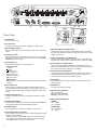
IMPORTANT SAFETY INSTRUCTIONS
1.
2.
3.
4.
5.
6.
7.
8.
9.
10.
11.
12.
13.
READ these instructions.
KEEP these instructions.
HEED all warnings.
FOLLOW all instructions.
DO NOT use this apparatus near water.
CLEAN ONLY with dry cloth.
DO NOT block any ventilation openings. Allow sufficient distances for adequate ventilation and install in accordance with the manufacturer’s instructions.
DO NOT install near any heat sources such as open flames, radiators, heat registers,
stoves, or other apparatus (including amplifiers) that produce heat. Do not place any open
flame sources on the product.
DO NOT defeat the safety purpose of the polarized or groundingtype plug. A polarized
plug has two blades with one wider than the other. A grounding type plug has two blades
and a third grounding prong. The wider blade or the third prong are provided for your
safety. If the provided plug does not fit into your outlet, consult an electrician for replacement of the obsolete outlet.
PROTECT the power cord from being walked on or pinched, particularly at plugs, convenience receptacles, and the point where they exit from the apparatus.
ONLY USE attachments/accessories specified by the manufacturer.
USE only with a cart, stand, tripod, bracket, or table specified by the manufacturer, or sold with the apparatus. When a cart is used, use caution when
moving the cart/apparatus combination to avoid injury from tip-over.
UNPLUG this apparatus during lightning storms or when unused for long
periods of time.
Important Product Information
The equipment is intended to be used in professional audio applications.
Note: This device is not intended to be connected directly to a public internet
network.
EMC conformance to Environment E2: Commercial and Light Industrial.
Testing is based on the use of supplied and recommended cable types.
The use of other than shielded (screened) cable types may degrade EMC
performance.
Changes or modifications not expressly approved by Shure Incorporated could
void your authority to operate this equipment.
This Class B digital apparatus complies with Canadian ICES-003. Cet appareil
numérique de la classe B est conforme à la norme NMB-003 du Canada.
Authorized under the verification provision of FCC Part 15B.
Please follow your regional recycling scheme for batteries, packaging, and
electronic waste.
14. REFER all servicing to qualified service personnel. Servicing is required when the apparatus has been damaged in any way, such as power supply cord or plug is damaged,
liquid has been spilled or objects have fallen into the apparatus, the apparatus has been
exposed to rain or moisture, does not operate normally, or has been dropped.
15. DO NOT expose the apparatus to dripping and splashing. DO NOT put objects filled with
liquids, such as vases, on the apparatus.
16. The MAINS plug or an appliance coupler shall remain readily operable.
17. The airborne noise of the Apparatus does not exceed 70dB (A).
18. Apparatus with CLASS I construction shall be connected to a MAINS socket outlet with a
protective earthing connection.
19. To reduce the risk of fire or electric shock, do not expose this apparatus to rain or
moisture.
20. Do not attempt to modify this product. Doing so could result in personal injury and/or
product failure.
21. Operate this product within its specified operating temperature range.
This symbol indicates that dangerous voltage constituting a risk of
electric shock is present within this unit.
This symbol indicates that there are important operating and maintenance instructions in the literature accompanying this unit.
WARNING: This product contains a chemical known to the State of California to cause cancer and birth
defects or other reproductive harm.
Information to the user
This equipment has been tested and found to comply with the limits for a Class
B digital device, pursuant to Part 15 of the FCC Rules. These limits are designed
to provide reasonable protection against harmful interference in a residential
installation. This equipment generates uses and can radiate radio frequency energy
and, if not installed and used in accordance with the instructions, may cause
harmful interference to radio communications. However, there is no guarantee that
interference will not occur in a particular installation. If this equipment does cause
harmful interference to radio or television reception, which can be determined
by turning the equipment off and on, the user is encouraged to try to correct the
interference by one or more of the following measures:
• Reorient or relocate the receiving antenna.
• Increase the separation between the equipment and the receiver.
• Connect the equipment to an outlet on a circuit different from that to which the
receiver is connected.
• Consult the dealer or an experienced radio/TV technician for help.
Patent Notice
U.S. Patent 5,999,631
Other patents pending
ii
Table of Contents
Table of Contents
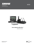
1 Dante Software by Audinate
Dante Controller
Overview2 Dante Virtual Soundcard
®
IntelliMix Operating Principles
2
Mixer Modes
2
Dual Mixer Operation
2
DFR and Audio Processing
2
Networking2
Model Variations
2
SCM820 Description
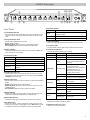
Front Panel
Rear Panel
3
3
4
Signal Path Diagram
5
Operating the Mixer
6
Front Panel Modes
6
Audio Mute and Bypass
6
Monitoring6
The SCM820 Graphical User Interface
Graphical User Interface (GUI)
Accessing the GUI
7
7
7
Installation8
Rackmounting8
Power8
8
Typical Audio Connections
Furnished Accessories
8
Configuring the Inputs and Outputs
9
Setting IntelliMix
Mixer Mode Descriptions
IntelliMix Parameters
Selecting the Mixer Mode
Single or Dual Mixer Operation
10
10
11
11
11
Networking12
Network Overview
Digital Audio Networking
12
12
14
14
14
Application Examples
15
Digital Feedback Reduction (DFR)
17
GUI Description
19
Creating a Link Group
15
Integrating with Other Systems
15
15
Configuring for Use with a Choir
Internet Calling
16
Logic16
Function17
Basic DFR Setup
17
18
Assigning DFR
Filter Types
18
Filter Width
18
Navigation Bar
Input Tab
Intellimix Tab
Digital Feedback Reduction (DFR) Tab
Output Tab
Link Group Tab
Preferences Tab
Log On Page
19
20
21
23
24
25
26
28
Troubleshooting29
Event Log
Front-Panel Error Messages
30
30
Specifications31
Analog Connections
31
Digital Signal Processing
31
Networking31
IP Ports and Protocols
32
Connector Diagrams
33
1
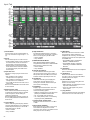
Overview
The Shure SCM820 is an 8-channel digital automatic mixer designed for use in speech applications, including sound reinforcement, broadcasting and audio
recording. It dramatically improves audio quality in any application where multiple microphones are required. The mixer uses IntelliMix® technology to select
channels to open to the mix bus, while attenuating other channels. The mixing mode is selectable to allow a range of automatic mixing styles.
The SCM820 can connect to a computer or 3rd party control system (AMX,
Crestron) for remote control and monitoring. The web browser-based
graphical user interface (GUI) enables custom IntelliMix configuration and
access to additional features.
Linking Mixers
SCM820-DAN mixers can be linked to form large automixes of up to 12
units (96 channels of audio). Mixers in the same link group operate under
shared IntelliMix settings. A back-panel auto link button enables mixers to
automatically link when they join the network. To link specific mixers, custom
groups can be created and managed from the GUI.
Model Variations
The following table describes the four SCM820 model variations:
Description
Model
Connector Type
Network Card
Block
Standard Ethernet
SCM820-DAN
Block
Dante Digital Audio
SCM820-DB25
DB25
Standard Ethernet
IN
+
+
IN
+
+
IN
+
+
IN
+
+
IN
+
A
INTELLIMIX
CHANNEL
B
manual
+
A
B
CH
OUT
AUX IN
mix a
L R
IN
+
direct out
IN
+
7
6
direct out
IN
+
direct out
IN
+
5
direct out
IN
+
4
direct out
IN
+
3
direct out
IN
+
2
direct out
IN
+
1
gate
mute
ovrd
gnd
8
direct out
phm 48 VDC
A
auto link
INTELLIMIX
manual
classic
+
+
+
+
+
+
+
+
8
direct out
direct out
7
6
direct out
direct out
5
direct out
4
direct out
3
direct out
AUX IN
MIX OUTPUTS
SCM820-DB25
2
direct out
A
B
CH
secondary
auto link
INTELLIMIX
manual
A
smooth
classic
AUX IN
MIX OUTPUTS
B
CH
A
line
+0dB
mic
+30dB
mic
+46dB
auto link
INTELLIMIX
DIRECT OUTPUTS 1-8
classic
lockout
reset
CHANNEL
B
manual
INPUTS 1-8
A
B
CH
line
+0dB
mic
+30dB
mic
+46dB
extreme
secondary
custom
Upgrading to Dante
reset
phm 48 VDC
smooth
L +R
SUM
MIX B
primary
extreme
custom
MIX A
lockout
CHANNEL
B
DIRECT OUTPUTS 1-8
dual mixer
SCM820-DAN-DB25
line
+0dB
mic
+30dB
mic
+46dB
phm 48 VDC
dual mixer
1
A
INPUTS 1-8
L +R
SUM
reset
extreme
custom
mix b
lockout
CHANNEL
B
smooth
+
line
+0dB
mic
+30dB
mic
+46dB
extreme
custom
dual mixer
dual mixer
00:0E:DD:AA:BB:CC
+
00:0E:DD:AA:BB:CC
IN
+
classic
+
00:0E:DD:AA:BB:CC
IN
+
smooth
+
mix b
SCM820-DAN
IN
+
gate
mute
ovrd
gnd
L R
gate
mute
ovrd
gnd
AUX IN
mix a
gate
mute
ovrd
gnd
OUT
+
gate
mute
ovrd
gnd
SCM820
Dante Digital Audio
gate
mute
ovrd
gnd
SCM820-DAN-DB25 DB25
primary
phm 48 VDC
auto link
lockout
reset
00:0E:DD:AA:BB:CC
SCM820
gate
mute
ovrd
gnd
Dual Mixer: Two separate buses provide independent automixes for
each mix output. This allows two entirely different mixes to result from
the same set of inputs. This is useful when the mixer is being used for
two applications. For example, set Mix A to Classic mode for sound
reinforcement, and set Mix B to Smooth for a broadcast feed. As a dual
mixer, channels can be routed to Mix A, Mix B, Mix A and B, or neither mix
bus.
Remote Control
gate
mute
ovrd
gnd
Single Mixer: Channels are routed to a single mix bus that sends the same
audio to both Mix A and B outputs. This allows the same program to be
sent to different rooms or recording applications. Output gain, parametric
equalizer and limiter can be set separately for each mix.
Audio can be played or recorded to a PC or Mac using Dante Virtual
Soundcard (DVS), using the computer’s standard Ethernet connection. A
license of DVS is included with every SCM820-DAN.
gate
mute
ovrd
gnd
The SCM820 can operate as a single or dual mixer:
Digital audio is carried over standard Ethernet using shielded Cat5e (or
higher) cables. Dante provides low latency, tight clock synchronization, and
high Quality-of-Service (QoS) to provide reliable audio transport to a variety
of Dante devices. Dante audio can coexist safely on the same network as IT
and control data, or can be configured to use a dedicated network.
gate
mute
ovrd
gnd
Dual Mixer Operation
DanteTM Digital Audio
gate
mute
ovrd
gnd
Classic
Classic mode emulates the default settings of the classic Shure SCM810
automixer. It is renowned for fast-acting, seamless channel gating and
consistent perceived ambient sound levels.
Smooth
Smooth mode dynamically balances system gain between open and
closed channels. The system gain remains consistent by distributing gain
across channels to equal one open channel. This mode incorporates
IntelliMix operating principles into a gain sharing mixing style.
Extreme
Extreme is an aggressive variation of Classic mode, configured to achieve
maximum gain before feedback by completely attenuating closed channels.
Custom
Custom mode allows individual IntelliMix parameters to be fine-tuned and
tailored from the GUI.
Manual
Manual mode deactivates IntelliMix to operate as a standard mixer.
Channel and mix equalization, output limiter and mix bus routing are still
active in this setting.
Networking
gate
mute
ovrd
gnd
The mixer operates in one of five Mix Modes: Classic, Smooth, Extreme,
Custom or Manual. The first three are factory settings that offer a range of
reliable automixing styles. IntelliMix is configurable in Custom mode and
turned off in Manual mode.
Additionally, the mixer provides adjustable input equalization, limiting and a
parametric output EQ to optimize the sound in any application.
gate
mute
ovrd
gnd
Mixer Modes
The SCM820 features two channels of Digital Feedback Reducer (DFR).
DFR uses Shure’s patented Adaptive Notch Filter algorithm to detect
feedback and deploy up to 16 narrow-band notch filters, dramatically
improving gain-before-feedback in a sound reinforcement system. DFR can
be applied to any two channels of the SCM820, including the mix outputs.
gate
mute
ovrd
gnd
• Noise Adaptive Threshold (NAT) manages the audio system by
distinguishing between dynamic audio (such as speech) and the noise
floor (such as air conditioning). It continuously adjusts the activation
threshold, so that only speech levels louder than the background noise
open a channel.
• MaxBus ensures that only one channel is opened per sound source,
reducing comb filtering for clear, intelligible speech.
• Number of Open Microphones Attenuation (NOMA) attenuates system
gain as additional channels are opened, providing consistent output levels
and better gain before feedback.
• Maintains the perceived ambient sound to achieve a natural sounding
audio program even during long pauses in conversation.
DFR and Audio Processing
gate
mute
ovrd
gnd
Expanding upon Shure's classic SCM810 IntelliMix technology, the digital
SCM820 delivers seamless automatic mixing by combining the following
functions:
gate
mute
ovrd
gnd
IntelliMix® Operating Principles
A standard SCM820 can be upgraded with the Dante Network Interface
Card (A820-NIC-DAN) to add full digital audio networking capabilities. This
replaces the standard Ethernet port with two Dante network ports. This
should only be installed by qualified service personnel. Visit www.shure.com
for more details.
2
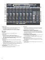
SCM820 Description
④
gain
1
SCM820
2
⑨⑩ ⑫ ⑬
⑤
IntelliMix®
3
4
5
6
7
MASTER
8
A B
AUX IN
LIM
A
B
0
low cut
-9
hi shelf
-18
gain
meter
limiter
-24
-36
power
HEADPHONE
ethernet
network audio
automix link
dual mixer
-48
L+R SUM
-60
push to solo | hold to mute
①
②
③
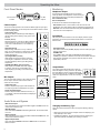
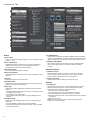
Front Panel
lockout
⑥ ⑦⑧ ⑪
⑭ ⑮
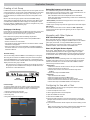
⑩ Mix Status Indicator
① Channel Mode Selection
Press the button to select the function of the channel knobs and monitor
LED rings. See the Audio Signal Adjustment section for details on each
mode.
② Assignable Channel Knob
Adjusts settings and status for each input:
Rotate: Adjusts a setting.
Momentary Press: Solos the channel to the headphone output.
Press and Hold: Mutes the audio or bypasses the EQ setting.
③ Monitor LED Ring
13 LED segments display gain setting, input signal meter, IntelliMix gain
meter, channel solo, or EQ setting.
④ Channel Status LED
LED
Mix Status
Green
Mix is selected for adjustment and listening on the
headphone output.
Amber
Limiter is bypassed.
Red
Mix is muted.
⑪ Audio Output Meters
Monitor the output signal level and limiter threshold for mix A and B.
⑫ LIM (Limiter) LEDs
Illuminate amber when the audio levels exceed the limiter threshold.
⑬ System Status Indicators
The LEDs illuminate to indicate system settings:
LED
Color
Status
power
Green
Unit is powered on.
ethernet
Green
Unit is connected to a network.
Green
All connected receive channels
are OK (receiving digital audio as
expected).
Flashing Green
⑤ Auxiliary Input Jack (1/8")
Unbalanced aux input sums left and right channels to mono. Front and
back panel aux inputs are summed to a mono signal and routed without
automixing to the mix outputs.
One or more connected receive
channels experiencing a
subscription error or is unresolved
(transmitting device is off,
disconnected, renamed or has
incorrect network setting).
Red
Clock synchronization problem.
Off
⑥ Master Output Knob
Adjusts settings and status of the mix outputs. See Front Panel Modes for
details.
No receive channels connected
(routing has not been established).
Green
Two or more mixers are connected
in a link group.
Flashing Green
Link Group is configuring.
Off
Mixer is in standalone mode.
Green
Mixer is set to Dual Mixer operation.
Off
Mixer is set to Single Mixer
operation.
Red
Front panel controls are locked.
Flashing Red
An adjustment is attempted in
lockout mode.
LED
Channel Status
Off
Channel is closed (attenuated in the automix).
Green
Channel is open (selected in the automix).
Amber
Channel EQ is bypassed.
Flicker Red
Signal is clipping. Set the channel to a lower input
gain level.
Solid Red
Channel is muted.
Rotate: Adjusts output gain or limiter threshold.
Momentary Press: Overrides a soloed channel to return the mix to the
headphone output.
Press and Hold: Mutes the audio or bypasses the limiter.
⑦ Master LED Ring
Displays gain setting or limiter threshold. A single LED represents each
mixer when they are both selected but set to different levels.
⑧ Master Mode Selection
Selects the function (gain or limiter) of the master knob and LED ring.
⑨ Mix Select Button
Selects Mix A, Mix B, or both for adjustment with the master knob and
monitoring on the LED ring and headphone output. Note: When both Mix
A and Mix B are selected, the headphone output only monitors Mix A.
network audio
automix link
dual mixer
lockout
⑭ Headphone Volume Knob
Adjust the volume of the headphone output.
⑮ Headphone Output Jack (1/4 in.)
Monitor a mix or a soloed channel.
3
IN
+
IN
+
A
INTELLIMIX
manual
A
classic
+
+
+
+
+
+
+
+
+
CH
B
direct out
8
7
direct out
6
direct out
direct out
5
direct out
4
direct out
3
2
direct out
phm 48 VDC
dual mixer
1
direct out
AUX IN
MIX OUTPUTS
INTELLIMIX
A
smooth
DIRECT OUTPUTS 1-8
classic
⑮
CH
B
line
+0dB
mic
+30dB
mic
+46dB
extreme
secondary
custom
MIX A
reset
CHANNEL
B
manual
INPUTS 1-8
lockout
auto link
⑭
A
L +R
SUM
line
+0dB
mic
+30dB
mic
+46dB
extreme
custom
④
⑤
⑥
⑧⑩
A
INTELLIMIX
CHANNEL
B
manual
classic
B
CH
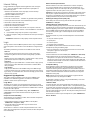
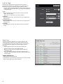
④ Auxiliary Input Jack
Unbalanced aux input sums left and right channels to mono. Front and
back panel aux inputs are summed to a mono signal and routed without
automixing to the mix outputs.
⑤ Channel Inputs 1–8
Active-balanced microphone- or line-level inputs.
Block Connectors
+ : Audio +
: Audio −
: Audio ground
gate: Logic gate out
mute: Logic mute in
ovrd: Logic override in
gnd: Logic ground
DB25 Connector
Pins: Audio plus, audio negative and audio ground. See Specifications
for details.
⑥ Direct Outputs 1–8
Each channel has a dedicated, impedance-balanced direct output on
the back panel that can be selected from one of five stages in the signal
path. See Configuring the Inputs and Outputs for details on direct output
routing.
⑦ Chassis Ground Screw 1–8
Provides an optional connection for microphone shield wire to chassis
ground.
⑧ IntelliMix Select Buttons
Scrolls through IntelliMix presets for each mix output. When dual mixer is
off, the A button sets the mode for both Mix A and Mix B.
⑨ Dual Mixer Button
Sets the SCM820 as a dual mixer, indicated by the green LED.
⑩ Channel Select Button and Display
Press to select a single channel (1–8) or all channels (A) when changing
input gain or phantom power.
• When all channels are selected (A), Input Level and Phantom Power
LED indicators only illuminate if all channels have the same setting.
• L is displayed when the mixer is in lockout mode.
⑮
⑰⑯⑱
phm 48 VDC
dual mixer
auto link
⑨⑫ ⑬
② AC Power Jack
Supplies AC power to the mixer when plugged into a power source.
③ Mix A and Mix B Outputs
Active balanced outputs connect to amplifiers, DSP, mixer, or recording
device.
⑪
⑭
reset
extreme
custom
① Power Switch
Turns the unit on or off.
lockout
auto link
line
+0dB
mic
+30dB
mic
+46dB
A
smooth
Rear Panel
primary
phm 48 VDC
dual mixer
MIX B
③
4
CHANNEL
B
00:0E:DD:AA:BB:CC
IN
+
00:0E:DD:AA:BB:CC
IN
+
gate
mute
ovrd
gnd
IN
+
gate
mute
ovrd
gnd
IN
+
gate
mute
ovrd
gnd
IN
+
smooth
mix b
①
②
+
gate
mute
ovrd
gnd
L R
gate
mute
ovrd
gnd
mix a
⑤ ⑥⑦
IN
gate
mute
ovrd
gnd
AUX IN
gate
mute
ovrd
gnd
①
②
④
OUT
gate
mute
ovrd
gnd
③
secondary
primary
⑰⑱⑰⑱
⑪ Input Gain Selection and LED Indicator
Sets the analog input gain level for the selected channel(s), illuminating
the green LED. All LEDs are off when the channel's audio source is set to
Network from the GUI.
⑫ Phantom Power Button and LED Indicator
Supplies 48 VDC phantom power to the selected channel(s), illuminating
the green LED. Phantom Power is disabled in the line (+0dB) gain setting.
⑬ Auto Link Button and LED Indicator
Enables networked SCM820-DAN mixers to automatically form a link
group. Link Groups enable a larger audio mix by incorporating inputs from
two or more mixers. See Link Groups for more details.
⑭ Lockout Button and LED Indicator
Hold for five seconds to disable front and back panel controls. The front
panel lockout LED illuminates red (flashing red during an adjustment
attempt) and the back panel channel display shows L.
⑮ Reset Button
Press and hold for five seconds to reboot the mixer with default system
settings restored.
⑯ Network Ports
RJ-45 jacks for network connection.
⑰ Network Status LED (Green)
Off = no network link
On = network link established
Flashing = network link active
⑱ Network Speed LED (Amber)
SCM820:
Off = 10 Mbps
On = 100 Mbps
SCM820-DAN:
Off = 10/100 Mbps
On = 1 Gbps
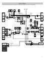
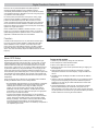
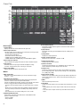
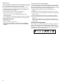
Signal Path Diagram
The following diagram shows the audio signal path and the routing options for several features (default configuration shown). Use the GUI to change the configuration.
Mix A
DFR
Input Meter
Mode
CHANNEL
INPUTS 1 - 8
Headphone
Mode
Input
Trim
Mute
Control
Digital Feedback
Reducer
Direct Outputs
(1-8)
Direct Output
Selection
Line +0
Mic +26
Mic +46
Analog
Mix B
D
Analog
A
Fader
EQ
A
D
Audio Source
(Channel)
Dante
Network
Routing
(Channel)
IntelliMix Gain
Gating
Logic
NOMA
IntelliMix A
IntelliMix Gain
Dante
Network
DFR
Headphone
Mode
NOMA
LIM
A
B
0
-9
Digital Feedback
Reducer
IntelliMix B
-18
-24
-36
-48
-60
Mix Outputs
(A and B)
Mix
Selection
Parametric EQ
AUX INPUT
Front Panel
Analog
Left
A
Right
A
D
Audio Source
(Aux)
Fader
Sum to
Mono
A
Left
Back Panel
Analog
D
D
A
EQ
Routing
(Aux)
Sum
Mix B
D
Single/Dual
Mixer
Sum
Aux R
A
Right
A
Digital Feedback
Reducer
DFR
D
Dante
Network
L/R
Link Group Outputs
from other units
IntelliMix®
1
gain
2
3
4
2
3
4
5
MASTER
6
7
8
AUX IN
6
7
8
AUX IN
low cut
A B
SCM820
LIM
power
B
A
0
ethernet
-9
hi shelf
automix link
-24
gain
dual mixer
-36
limiter
HEADPHONE
network audio
-18
meter
-48
-60
L+R SUM
lockout
push to solo | hold to mute
5
Output Pad
(-0, -20, -46)
Mix A
Analog
Output Pad
(-0, -20, -46)
Mix B
Analog
Dante
Network
Aux Output
L/R
Global/Local (Aux)
IntelliMix®
1
Limiter
Sum
Aux L
D
gain
Master Fader
Sum
Mix A
MASTER
low cut
A B
power
B
A
0
ethernet
Mix B
HEADPHONE
automix link
-24
gain
dual mixer
-36
limiter
Link Group Outputs
to other units
network audio
-18
meter
Sum
Mix A
Sum
Mix B
SCM820
LIM
-9
hi shelf
Mix A
Global/Local (Mix)
Dante
Network
-48
-60
L+R SUM
lockout
push to solo | hold to mute
IntelliMix®
1
gain
2
3
4
5
6
7
8
low cut
MASTER
A B
SCM820
LIM
B
A
AUX IN
0
meter
gain
limiter
power
ethernet
-9
hi shelf
-18
network audio
-24
automix link
HEADPHONE
dual mixer
-36
-48
-60
L+R SUM
lockout
push to solo | hold to mute
IntelliMix®
1
gain
2
3
4
2
3
4
5
6
7
8
6
7
8
low cut
MASTER
A B
SCM820
LIM
B
A
AUX IN
0
gain
limiter
HEADPHONE
network audio
-18
meter
power
ethernet
-9
hi shelf
automix link
-24
dual mixer
-36
-48
-60
L+R SUM
lockout
push to solo | hold to mute
IntelliMix®
1
gain
5
low cut
MASTER
A B
AUX IN
SCM820
LIM
A
B
0
meter
gain
limiter
power
ethernet
-9
hi shelf
-18
network audio
-24
automix link
HEADPHONE
dual mixer
-36
-48
-60
L+R SUM
lockout
push to solo | hold to mute
IntelliMix®
1
gain
2
3
4
2
3
4
5
MASTER
6
7
8
AUX IN
6
7
8
AUX IN
low cut
A B
SCM820
LIM
A
B
A
B
0
gain
limiter
HEADPHONE
network audio
-18
meter
power
ethernet
-9
hi shelf
automix link
-24
dual mixer
-36
-48
-60
L+R SUM
lockout
push to solo | hold to mute
IntelliMix®
1
gain
5
low cut
MASTER
A B
0
-18
meter
gain
limiter
SCM820
LIM
-9
hi shelf
-24
-36
power
ethernet
HEADPHONE
network audio
automix link
dual mixer
-48
L+R SUM
push to solo | hold to mute
-60
lockout
5
iiiii
iiiii
iiiii
i iiii
2
3
low cut
4
5
6
3
7
8
AUX IN
MASTER
AUX IN
A B
A
0
-9
-18
gain
hi shelf
limiter
4MASTER
SCM820
LIM
-24
-36
B
power
ethernet
-60
push to solo | hold to mute
HEADPHONE
network audio
automix link
dual mixer
-48
L+R SUM
meter
lockout
5
A
-∞ dB
+18 dB
+0 dB
low cut-90
-18
hi shelf-24
-36
ch. meter-48 i i i
-60
i i
push to solo | hold
to mute
gain
low
cut
gain
gain
iiiii
ii ii i
iiii
hi cut
shelf
low
ch.
meter
higain
shelf
ii ii i
low
cut
ch.
meter
iiiii
iiiiii
iiii
For Mix
92 Hz+0 dB
-∞ dB
+18 dB
Outputs
92 Hz
iiiii
Mode
Selector
iiiii
L+R SUM
iiiii
limiter
For Channels 1-8
and Aux
+18 dB
i iiii
A gain
B LIM
iiiii
2
-∞ dB
iiiii
IntelliMix®
1
gain
hi shelf
meter
iiiii
low cut
hi shelf
ch. meter
iiiii
IntelliMix®
1
gain
+0 dB
iiiii
Front Panel Modes
+0 dB
Operating
the Mixer
i iiii
iiiii
gain
low cut
higain
shelf
low
cut
ch.
meter
iiiiii
iiiii
iiiii
Channel Inputs
i iiii
low cut
hi shelf
ch. meter
gain
low cut
gain
hi shelf
cut
ch.low
meter
iiiii
hi shelf
gain
ch. meter
-∞ dB
+18
+0dB
dB
25 Hz
25 Hz
320 Hz
92 Hz
320 Hz
The channel knobs operate in five modes for different types of input signal
+0 dB
dB select
+18 dB
adjustment and display. Use the front panel mode selection button-∞to
92 Hz
hi gain
shelf
from the following modes.
ch.
meter
low
cut
+0 dB320 Hz
25 Hz
higain
shelf
Channel Gain (gain)
+0 dB
gain
ch.
lowmeter
cut
+0
dB+18 dB
-∞
dB
low cut
Adjust gain within a 128 dB range while displaying
higain
shelf
hi shelf
92 Hz
cut
meter
the gain setting on the LED ring. Unity gain is at the ch.low
25 Hz
320 Hz
ch.
meter
gain
hi shelf
low cut
9th LED.
ch. meter
hi shelf
-12
dB
+12dB
dB
+0 dB+18
-∞ dB
ch. meter
Low Cut (low cut)
gain
cut
-12 dB 92 Hz
+12 dB
Adjust the frequency of the low cut filter (6 dB/octave low
gain
hi shelf
25 Hz
320 Hz
cut
ch.low
meter
+0 dB
from 25 to 320 Hz). Use to remove low-frequency
hi gain
shelf
ch.
meter
low
cut
noise such as table vibrations or air-conditioning
-12 dB
+12 dB
hi shelf
92 Hz
rumble.
gain
ch. meter
25 Hz
320 Hz
gain
low
cut
-16 dBFS
low
High Shelf (hi shelf)
hi cut
shelf
+0 dB
-12 dB
+12 dB
higain
shelf
ch.
meter
gain
-16
dBFS
Adjust the high shelf boost or cut (± 12 dB at 5
low
cut cut
ch.
meter
low
hi shelf
kHz). Use to add presence to muddy vocals, temper hi shelf
25 Hz
320 Hz
ch. meter
ch. meter
gain
sibilant vocals, or enhance the sound of off-axis
-60 dBFS
-16+0
dBFS
dB0 dBFS
low cut
gain
lavalier microphones.
hi shelf
dB 0+12
dB
-60-12
dBFS
dBFS
cut
ch.low
meter
hi gain
shelf
Input Signal Meter (ch. meter)
-16 dBFS
ch.
meter
low
cut
-60 dBFS
LEDs display the input signal level in real-time.
+0 dB0 dBFS
hi shelf
gain
ch. meter
-12 -15
dB dB +12 dB
Channel gain is adjustable in this mode, and will
low cut
gain
hi shelf
momentarily display channel gain setting during
low cut
-60 dBFS
-15 dB0 dBFS
ch. meter
gain
-16 dBFS
gain
hi
shelf
adjustments.
low cut
low
cut
ch.
meter
hi
shelf
-15 dB +12 dB
-12
dB
hi
shelf
IntelliMix Gain Meter (gain and ch. meter)
ch. meter
gain
ch. meter
low cut
LEDs display the IntelliMix attenuation applied
-80 dB
0 dB
hi shelf
gain
-16 dBFS0 dBFS
-60 dBFS
IntelliMix®
cut
ch.low
meter
in realtime. Channel gain is
adjustable in this
-15 dB
-80 dB
0 dB
hi gain
shelf
1
2
3
4
5
mode, displaying the setting on the LEDs during
low
cut
ch.
meter
-80 dB
0 dB
hi shelf
adjustments.
ch. meter
iiii
iii
iiiii i i
ii ii i
i iiii
iiiii
iiiiii
iiiii
Headphone Output
Use the front panel headphone jack for monitoring
audio. By default, the headphones monitor the mix prefader/post-EQ (change to post-fader/post-limiter from
GUI > Preferences Tab).
Solo to Headphones
A channel can be soloed to the headphone jack.
Solo Channel: Press a channel knob to solo that channel to the
headphones. The other LED rings dim to highlight the soloed channel.
Exit Solo: Press the soloed channel knob or press the Master knob to
return the mix to the headphones.
iiiii
iiii
ii ii i
Monitoring
iiiiii
iiiii
iiiii
i iiii
iiii
iiiii
iiiii
i iiii
iiii
iiiii
iiii
iiiiii
ii ii i
iiiii
i iiii
iiiiii
iiiiii
ii
iiii i i
iiii
iiiii i
i iiii
ii ii i
Input Meters
The front panel channel meters can be set to display real-time signal
information. Use the front panel mode selection button to scroll to the
desired mode:
IntelliMix®
1
iiiiii
2
3
4
5
6
7
8
AUX IN
hi shelf
meter
i iiii
L+R SUM
iiiii
iiii
iiiiii
gain
low cut
iiii
iiiiii
iiiii
ii ii i
iiii
iiiiii
iiiii
i iiii
iiii
iiiiii
iiiiii
iiiii
iiii
i iiii
iiiii
i iiii
iiiiii
ii
iiii i i
iiii
iiiii i
i iiii
i iiii
iiii
iiiiii
iiiiii
iiiii
i iiii
iiiii
iiii
i iiii
iiiii
iiii
iiiiii
i iiii
Input Signal Level
The channel meter mode (ch. meter) displays real-time audio input signal
level for each channel.
IntelliMix Gain
The IntelliMix meter mode (gain and ch. meter illuminated) displays
IntelliMix gain operation in real-time across the channel LEDs. Channels
that gate open will display more gain than channels that are closed
(attenuated) in the mix.
iiiiii
iiii
iiiiii
iiiii
i iiii
iiii
iiiiii
iiiii
i iiii
iiiiii
iiii
iiii
iiiiii
iiiiii
iiiii
iiii
iiiii
iiiii
i iiii
i iiii
i iiii
iiiiii
i iiii
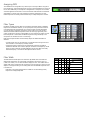
Output Meters
iiii
The 6output meters
7 indicate8 the level of each mixAUX IN
before the digital-to-analog conversion. By default,
gain
the meter displays average and peak audio levels.
-16 dBFS0 dBFS
-60 dBFS
low cut
It is good practice to use −18 dBFS on the SCM820
hi shelf MASTER -15 dB
-80 dB
0 dB
gain
ch. meter
push to AsoloB| hold to mute meter as an approximation of 0 VU on an analog
low cut
MASTER
hi shelf
+0 dB
meter.
ch. meter MASTER
-60 dBFS 0AdBFS
B
iiiii
iiii
iiiiii
iiii
iiiiii
iiii
iiiiii
iiii
iiii
iiii
iiiiii
iiii
iiiiii
iiii
iiii iiii
iiii
i iiii
A
B
iiiiii
iiiiii
-24
dBFS
-∞MASTER
dB
+18+0dBdB A B
MASTER
-80 dB
0 dB
A BB
-24dBFS
dBFS
-24
i iiii
iiii
gain
limiter
gain
A
iiiii
iiiiii
MASTER
MASTER
B
i iiii
iiii
iiiii
limiter
+0 dB
gainA i i i B
-∞ -24
dB dBFS
+18 dBgain
i i
iii
iiiiii
i i
iii
i i i iii i
i i i ii i i i
limiter
-50 dBFS
-2 dBFS
limiter
MASTER
-50 dBFS
-2 dBFSgain
limiterA B
-50 dBFS
-2 dBFS
gain
MASTER
+0 dB
limiter
iiiiii
iiii
iiiiii
i iiii
iiiii
-60
iiii
iiiiii
iiiiii
A
iiii
Yellow (5)
Clip
Normal peaks
Green (4)
Green (3)
Green (2)
Signal Level (dBFS)
0 to -6
-6 to -9
-9 to -18
-18 to -24
Signal Present
Green (1)
-24 to -36
-36 to -48
-48 to -60
B
i iiii
iiiii
iiiiii
gain
limiter
Red (7)
Description
i iiii
i iiii
iiiii
iiii
Mute Channel Input
MASTER
gain
-∞ dB
+18 dBlimiter
A B
Press and hold the input channel knob while in gain or ch. meter
mode.
The
-24 dBFS
-50 dBFS
-2 dBFS
channel status LED turns red.
MASTER
Mute Mix Output
gain
limiter
A B
-24status
dBFS
Press and hold the MASTER knob while in gain mode. The mix
LED
-50 dBFS
-2 dBFS
turns red.
gain
Bypass Input EQ
limiter
Press and hold the input channel knob while in low cut or hi shelf mode. The
-50 dBFS
-2 dBFS
channel status LED turns amber.
Bypass Output Limiter
Press and hold the MASTER knob while in limiter mode. The mix status
LED turns amber.
iiii
iiiiii
i iiii
iiiii
iiii
iiiiii
i iiii
iiiii
iiiiii
6
-24
-36
power
ethernet
network audio
automix link
dual mixer
-48
iiiii
-∞ dB
+18 dB
-24 dBFS
-50 dBFS
-2 dBFS
LED
Yellow (6)
0 dB
gain
limiter
iiiiii
+18 dB
MASTER
iiiii
iiii
iiiiii
limiter
+0
-15dB
dB
+18
-80
dB dB
MASTER
i iiii
iiiiii
iiiiii
i iiii
i iiii
gain i i iii
gainA B
limiter
+18 dB
iiiii
hi shelf
ch. meter
iiiiii
-∞ dB
gain
-∞ dB
-∞ dB
low cut
iiiii
Audio Mute and Bypass
gain
limiter
iiiiii
iiiiii
MASTER
i iiii
iiiii iiiii
hi shelf
ch. meter
+0
-15dB
dB A i iiBii
+0 dBgain
-80 dB limiter0 dB
iiiii
gain
low cut
iiiii
Output Gain (gain)
Rotate to adjust the output gain of the selected mix.
The output signal level is displayed on the meters.
Limiter Threshold (limiter)
Rotate to adjust the limiter threshold of the mix (−2
to −50 dBFS). The limiter threshold level is displayed
on the meters.
B
i iiii
i iiii
iiiii
The mix output knob operates in two modes to control
the mix output. Use the master function button to
select one of two modes.
A
-9
-18
iiiii
Mix Outputs
L+R SUM
i i i i ii
ii ii
iiii
iiii
i iiii
i iiii
LIM
0
iiiiii
meter
A B
i iiii
iiiii
hi shelf
MASTER
i iiii
iiiii
low cut
i iiii
iiiii
gain
Changing the Metering Type
Go to the Preferences tab of the GUI to change the following metering
options:
• Meter Type: Change the input and output meters from displaying VU +
Peak (default) to VU or Peak.
• IntelliMix Gain Metering: The Input tab of the GUI can display input
signal level (default) or IntelliMix gain metering in realtime.
lockout
The SCM820 Graphical User Interface
Graphical User Interface (GUI)
The SCM820 graphical user interface (GUI) enables comprehensive
control of the mixer from a web browser. The GUI is hosted from a
webserver embedded on the SCM820, and is accessible from any
computer on the network. Use the GUI for the following functions:
• Manage mixers from a remote location.
• Customize IntelliMix parameters.
• Form large automixes with custom link groups.
• Assign the direct outputs in the signal path.
• Configure Redundant or Split networks.
• Set up and monitor DFR for up to two channels in each mixer.
Accessing the GUI
System Requirements
The Shure Web Server Discovery application finds all Shure devices on
the network that feature a web-based GUI. Follow these steps to install
the software and access the SCM820 GUI:
• Windows: Windows XP (32 and 64 bit), Windows Vista and Windows 7
• Apple: Mac OSX 10.6.0 and higher
• Latest version of Adobe Flash Player
• Bonjour software (bundled with the Shure Discovery app)
• The GUI is supported on the following web-browsers: Internet Explorer,
Firefox, Safari and Chrome.
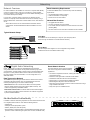
① Install the Shure Discovery application
Load the Shure USB drive and install the application. This
automatically installs the required Bonjour device discovery tool on
the computer. This application is also available from www.shure.com.
② Connect the network
Ensure the computer and the mixer are on the same network.
③ Launch the Discovery application
The app displays all Shure devices that feature a GUI.
①
secondary
primary
secondary
primary
secondary
primary
secondary
primary
secondary
②
③
primary
secondary
primary
IntelliMix®
1
gain
2
2
3
4
3
4
2
3
4
2
3
4
5
MASTER
6
7
8
6
7
8
AUX IN
6
7
8
AUX IN
6
7
8
AUX IN
AUX IN
low cut
A B
SCM820
LIM
A
B
0
gain
limiter
HEADPHONE
network audio
-18
meter
power
ethernet
-9
hi shelf
⑤ Bookmark the GUI (recommended)
Bookmark the device's DNS name to access the GUI without the
Shure Discovery app.
5
A B
lockout
A
B
0
power
ethernet
-9
gain
limiter
ROOM 5
SCM820-Dan-ffeee5.local
192.168.200.22
CONFERENCE
SCM820-ffaaa2.local
192.168.200.23
Dante
SCM820
LIM
HEADPHONE
network audio
-18
meter
SCM820-DAN
dual mixer
-60
MASTER
hi shelf
SCM820
automix link
-24
-36
-48
L+R SUM
push to solo | hold to mute
④ Open the SCM820 GUI
Double-click on a device to open its GUI in a web browser.
IntelliMix®
1
gain
low cut
automix link
-24
dual mixer
-36
-48
L+R SUM
-60
lockout
push to solo | hold to mute
IntelliMix®
1
gain
5
MASTER
low cut
A B
SCM820
LIM
A
B
A
B
0
gain
limiter
HEADPHONE
network audio
-18
meter
power
ethernet
-9
hi shelf
automix link
-24
dual mixer
-36
-48
L+R SUM
-60
lockout
push to solo | hold to mute
IntelliMix®
1
gain
5
MASTER
low cut
A B
SCM820
LIM
0
gain
limiter
HEADPHONE
secondary
network audio
-18
meter
power
ethernet
-9
hi shelf
-24
automix link
-36
dual mixer
primary
-48
L+R SUM
-60
lockout
push to solo | hold to mute
IntelliMix®
1
gain
2
3
4
2
3
4
5
MASTER
6
7
8
AUX IN
6
7
8
AUX IN
low cut
A B
SCM820
LIM
A
B
A
B
0
gain
limiter
HEADPHONE
network audio
-18
meter
power
ethernet
-9
hi shelf
automix link
-24
dual mixer
-36
-48
L+R SUM
-60
lockout
push to solo | hold to mute
IntelliMix®
1
gain
IntelliMix®
1
2
gain
5
MASTER
low cut
A B
SCM820
LIM
0
-9
hi shelf
-18
meter
gain
limiter
-24
-36
power
ethernet
3
4
5
6
7
MASTER
8
-60
primary
secondary
primary
secondary
primary
secondary
primary
secondary
primary
gain
IntelliMix®
1
gain
power
ethernet
HEADPHONE
network audio
automix link
dual mixer
-48
-60
lockout
⑤
secondary
primary
secondary
primary
secondary
primary
SCM820-Dan-ffeee5.local
192.168.200.22
SCM820-ffaaa2.local
MXWAPT8-fffee8.local
192.168.200.23
192.168.200.24
primary
secondary
2
3
4
2
3
4
5
MASTER
6
7
8
AUX IN
6
7
8
AUX IN
low cut
A B
A
B
A
B
0
gain
limiter
power
ethernet
HEADPHONE
network audio
-18
meter
automix link
-24
dual mixer
-36
IntelliMix®
1
-48
L+R SUM
-60
lockout
push to solo | hold to mute
gain
2
3
4
5
MASTER
6
7
8
AUX IN
6
7
8
AUX IN
low cut
5
low cut
MASTER
A B
0
gain
limiter
power
ethernet
IntelliMix®
1
SCM820
LIM
A
B
A
B
power
gain
HEADPHONE
ethernet
0
-9
gain
2
3
4
5
6
7
MASTER
8
AUX IN
low cut
network audio
A B
SCM820
A
0
-18
meter
dual mixer
gain
limiter
-24
-36
B
power
ethernet
HEADPHONE
network audio
automix link
dual mixer
-48
-48
dual mixer
LIM
-9
hi shelf
automix link
-24
-36
limiter
L+R SUM
-60
L+R SUM
lockout
push to solo | hold to mute
automix link
-24
-36
A B
-18
meter
HEADPHONE
network audio
-18
meter
hi shelf
SCM820
LIM
-9
hi shelf
primary
SCM820
LIM
-9
hi shelf
IntelliMix®
1
B
-24
-36
limiter
L+R SUM
push to solo | hold to mute
secondary
gain
A
0
-18
meter
primary
secondary
SCM820
LIM
-9
hi shelf
lockout
④
secondary
A B
AUX IN
low cut
HEADPHONE
network audio
automix link
dual mixer
-48
L+R SUM
push to solo | hold to mute
-60
push to solo | hold to mute
lockout
-48
L+R SUM
-60
lockout
push to solo | hold to mute
IntelliMix®
1
gain
2
3
4
5
6
7
8
low cut
MASTER
AUX IN
A B
A
B
0
power
ethernet
gain
HEADPHONE
gain
-24
automix link
limiter
-36
dual mixer
-60
3
4
5
MASTER
SCM820
LIM
gain
2
3
4
5
dual mixer
-36
limiter
-48
L+R SUM
6
7
8
MASTER
AUX IN
A B
-60
lockout
SCM820
LIM
A
B
0
gain
limiter
HEADPHONE
network audio
-18
meter
power
ethernet
-9
hi shelf
IntelliMix®
1
gain
automix link
-24
dual mixer
-36
-48
L+R SUM
-60
lockout
push to solo | hold to mute
2
3
4
2
3
4
5
MASTER
6
7
8
AUX IN
6
7
8
AUX IN
low cut
A B
3
4
2
3
4
5
MASTER
6
7
8
AUX IN
6
7
8
AUX IN
A B
A
B
A
B
0
power
ethernet
-9
gain
limiter
gain
SCM820
A
B
B
power
HEADPHONE
ethernet
network audio
automix link
-24
dual mixer
-36
limiter
SCM820
LIM
-48
L+R SUM
HEADPHONE
-60
lockout
push to solo | hold to mute
network audio
-18
meter
A
0
-18
meter
2
hi shelf
LIM
-9
hi shelf
IntelliMix®
1
gain
low cut
HEADPHONE
network audio
automix link
-24
push to solo | hold to mute
IntelliMix®
1
gain
low cut
power
ethernet
0
-9
-18
meter
lockout
push to solo | hold to mute
A B
hi shelf
-48
L+R SUM
2
low cut
network audio
-18
meter
IntelliMix®
1
SCM820
LIM
-9
hi shelf
automix link
-24
dual mixer
-36
-48
5
-60
MASTER
A B
lockout
0
-18
meter
gain
limiter
-24
-36
IntelliMix®
1
gain
SCM820
LIM
-9
hi shelf
power
ethernet
5
MASTER
low cut
-60
A B
SCM820
LIM
0
-9
hi shelf
HEADPHONE
-18
meter
network audio
gain
-24
-36
limiter
automix link
power
HEADPHONE
ethernet
network audio
automix link
dual mixer
-48
dual mixer
L+R SUM
-48
L+R SUM
push to solo | hold to mute
-60
push to solo | hold to mute
lockout
lockout
IN
+
IN
+
IN
+
IN
+
gate
mute
ovrd
gnd
IN
+
gate
mute
ovrd
gnd
IN
+
gate
mute
ovrd
gnd
IN
+
gate
mute
ovrd
gnd
IN
+
gate
mute
ovrd
gnd
L R
gate
mute
ovrd
gnd
AUX IN
gate
mute
ovrd
gnd
OUT
mix a
gate
mute
ovrd
gnd
reset
If the Discovery application is not installed, the SCM820 GUI can be
accessed by typing the DNS name into an internet browser. The DNS
name is derived from model of the unit (SCM820 or SCM820-DAN), in
combination with the last three bytes (six digits) of the MAC address,
and ending in .local.
primary
Accessing the GUI without the Discovery App
A
INTELLIMIX
CHANNEL
B
manual
A
smooth
classic
+
+
+
+
+
+
+
+
+
direct out
8
direct out
7
direct out
6
direct out
5
direct out
4
direct out
3
direct out
2
direct out
CH
line
+0dB
mic
+30dB
mic
+46dB
secondary
custom
mix b
B
extreme
00:0E:DD:AA:BB:CC
1
dual mixer
primary
phm 48 VDC
IntelliMix
direct out
lockout
reset
00:0E:DD:AA:BB:CC
L+R SUM
push to solo | hold to mute
IntelliMix®
1
gain
low cut
Format Example: If the MAC address of a unit is 00:0E:DD:AA:BB:CC,
then the link is written as follows:
• SCM820-DAN: http://SCM820-DAN-aabbcc.local
• SCM820: http://SCM820-aabbcc.local
7
Installation
Power
Furnished Accessories
IN
+
IN
+
IN
+
INTELLIMIX
A B
manual
CHANNEL
A
smooth
classic
+
+
+
+
+
+
+
+
B
direct out
8
7
direct out
6
direct out
direct out
5
direct out
4
direct out
3
2
direct out
direct out
line
+0dB
mic
+30dB
mic
+46dB
extreme
+
secondary
custom
mix b
CH
00:0E:DD:AA:BB:CC
IN
+
gate
mute
ovrd
gnd
IN
+
gate
mute
ovrd
gnd
IN
+
gate
mute
ovrd
gnd
IN
+
gate
mute
ovrd
gnd
IN
+
gate
mute
ovrd
gnd
LR
gate
mute
ovrd
gnd
AUX IN
gate
mute
ovrd
gnd
OUT
mix a
gate
mute
ovrd
gnd
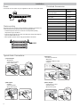
Connect the unit to AC power using the supplied IEC cable. Turn on the power switch.
1
primary
phm 48 VDC
dual mixer
auto link
lockout
reset
Hardware Kit (SCM820, SCM820-DAN)
90A20082
Hardware Kit (SCM820-DB25,
SCM820-DAN-DB25)
90BA8100
Ethernet cable
95D15103
Power Cable
region dependent,
see table
USB Flash Drive
95A20438
Power Cable by Region
Part Number
US
95B8389
Brazil
95A14336
Rackmount the mixer using the screws and washers supplied in the Hardware Kit.
Follow these general best practices when rackmounting equipment:
Argentina
95A14335
• Ambient temperature of the rack should not exceed specified operating
temperature range of the device.
• Keep fan inlet and side air vents clear from obstructions and provide adequate
space for airflow within the rack.
• When possible, provide 1 RU of empty space between each device.
Europe
95C8247
UK
95A8713
Japan
95B9021
China
95B9073
Korea
95B9074
Australia
95A9128
Rackmounting
gain
1
2
3
4
5
6
7
8
AUX IN
low cut
MASTER
A B
LIM
A
B
gain
automix link
-24
dual mixer
-36
limiter
HEADPHONE
network audio
-18
meter
power
ethernet
0
-9
hi shelf
-48
L+R SUM
-60
lockout
push to solo | hold to mute
gain
1
2
3
4
5
6
7
8
AUX IN
low cut
MASTER
A B
LIM
A
B
gain
automix link
-24
dual mixer
-36
limiter
HEADPHONE
network audio
-18
meter
power
ethernet
0
-9
hi shelf
-48
L+R SUM
-60
lockout
push to solo | hold to mute
gain
1
2
3
4
5
6
7
8
AUX IN
low cut
MASTER
A B
LIM
A
0
-9
hi shelf
-18
meter
gain
-24
-36
limiter
B
power
ethernet
HEADPHONE
network audio
automix link
dual mixer
-48
L+R SUM
-60
push to solo | hold to mute
lockout
Typical Audio Connections
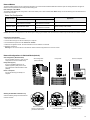
② Aux Inputs
Aux-level sound sources:
• MP3 player
• Computer headphone output
• CD player
① Channel Inputs
• Microphones
• Insert send from a mixer
• Dante network audio
Inputs 1-8
6
7
MASTER
8
A B
gain
+
ethernet
HEADPHONE
network audio
automix link
dual mixer
-36
-48
+
+
-60
L+R SUM
lockout
1
+
+
power
B
-24
limiter
+
+
A
0
-9
-18
+
+
LIM
AUX IN
+
1
2
3
Aux In
4
Inputs 1-8
+
L+R
SUM
5
+
6
+
+
Aux In
+
Inputs 1-8
TS
MIX OUTPU
+
L+R
SUM
8
+
MIX B
MIX A
③ Mix Outputs
• Amplifier
• Powered speakers
• Mixer channel inputs
+
+
+
+
+
+
1
2
3
+
+
+
+
+
+
+
+
+
④ Direct Outputs
• Insert returns to a mixer
• Recording device
• Mixer channel inputs
+
4
+
5
6
7
+
Aux In
+
Inputs 1-8
MIX OUTPUTS
+
+
+
L+R
SUM
+
+
8
+
MIX B
MIX A
+
3
4
5
6
7
8
1
1
2
+
Aux In
L+R
SUM
uts 1-8
Direct Outp
6
7
Configuring the Inputs and Outputs
Unless where noted, configurations can be made from the hardware or from the GUI.
Inputs
Direct and Mix Outputs
① Select the Audio Source (GUI only)
• Analog (default): Audio is from a microphone or line-level audio source
connected to a channel input on the mixer back panel.
• Network: Audio is from the Dante digital audio network. Go to the Inputs
tab of the GUI to select Network audio for each desired channel. Dante
Controller software is required to properly route audio to the channel
inputs.
⑤ Assign the Direct Outputs (GUI Only)
Assign the Direct Output for each channel from the Output tab of the GUI.
• Pre-EQ: After the Input Gain
• Post-EQ: After the EQ blocks
• Post-Fader: After the channel fader
• IntelliMix: After the IntelliMix gating decision
• IntelliMix NOMA: After IntelliMix gating and NOMA decisions
② Select the Input Gain
Select the analog input gain for each channel. No gain is applied for
analog line-level or when the audio source is set to Network.
• Mic (+46dB): For less sensitive microphones, such as dynamics.
• Mic (+26dB): For loud talkers or sensitive microphones such as
condensers.
• Line (+0dB): For line-level sources such as mixer inserts.
⑥ Set Mix Output Level (GUI Only)
Set the Output level according to the input of the connecting equipment:
• Line (-0) (default): No attenuation to the output level.
• Aux (-20): The signal is attenuated 20 dB to avoid clipping a line input.
• Mic (-46): The signal is attenuated 46 dB to match a microphone input.
③ Supply Phantom Power
Supply 48 V phantom power to the channel when using condenser
microphones. (Phantom power is disabled when Input gain is set to Line.)
④ Adjust Channel EQ
Adjust the high- and low-frequency equalization to improve intelligibility
and reduce undesired noise:
• Low Cut: Ideal for attenuating low-frequency vibration caused by table
vibrations or air-conditioning rumble. Adjust the frequency of the 12 dB/
octave filter from 25 - 320 Hz.
• High Shelf: For tempering sibilant speech or enhancing the sound of offaxis microphones. Use this to boost or cut the signal by 12 dB at 5 kHz
with a slop of 12dB/octave.
⑦ Set the Limiter
The output limiter prevents distortion during loud program peaks without
affecting normal program levels. This prevents overloading the devices
connected to the mixer outputs.
⑧ Adjust the Output Gain
Adjust the overall output level of the mix.
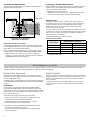
Auxiliary (Aux) Input
The SCM820 features two auxiliary inputs: an 1/8” jack on the front panel and a back panel input (block connector or RCA connectors, depending on
the model). Each input sums the left and right channel to a mono signal. This mono signal is routed directly to the mix outputs, bypassing the automixing
process. Use this input for sources such as an MP3 player or computer speaker output.
Digital Channels
When the mixer is connected to a Dante network, the left and right channels are accessible before they sum to the mono signal for the mix outputs. Use
the Aux L and Aux R channels in Dante Controller to route audio to and from the aux channel.
9
Setting IntelliMix
The SCM820 uses IntelliMix to select channels to open in a mix, while attenuating the gain of closed channels. IntelliMix is available in three presets and
can be customized to excel in any application where multiple microphones are used at once. In all modes (except Manual), MaxBus ensures that only one
channel is opened per sound source.
Mixer Mode Descriptions
The SCM820 features five mix modes: Classic, Extreme, Smooth, Custom or Manual.
Classic
Classic mode emulates the classic Shure SCM810 automixer (in its default
settings). It is renowned for fast-acting, seamless channel gating and
consistent perceived ambient sound levels. The Classic mode excels in
most applications, specifically sound reinforcement and teleconferencing.
Gating Style:
Full
Gain Scaling:
Fixed
Off Attenuation:
−15 dB
Last Mic Lock On:
Enabled
Smooth
Smooth dynamically balances system gain between open and closed
channels. The system gain remains consistent by distributing gain across
channels to equal one open channel. It incorporates IntelliMix operating
principles into a gain sharing mixing style, making it ideal for broadcast and
recording applications.
Gating Style:
Relative
Gain Scaling:
Adaptive
Off Attenuation:
Disabled
Last Mic Lock On:
Disabled
Tip: Unroute all unused channels to the mix bus. This will ensure the
most consistent noise floor in Smooth mode.
Channel Gain in Classic Mixer
1 Talker
2+ Talkers
-15 dB
-15 dB
Full gain is applied as the
channel opens; off attenuation
gain is applied to all channels.
-15 dB
-15 dB
-15 dB
-15 dB
-15 dB
Channel Gain in Smooth
Mixer
-15 dB
1 Talker
2+ Talkers
-15 dB
-15 dB
Relative gain is applied to the
open-15
channel;
all channels
dB
adaptively attenuate to maintain
system
-15 dB gain.
-15 dB
As additional channels open,
gain
-15 dBis adaptively distributed
across all channels to
system gain.
-15 maintain
dB
-15 dB
Extreme
Channel Gain in Extreme Mixer
Extreme is an aggressive variation of the Classic mode, configured to
achieve maximum gain before feedback by completely attenuating closed
channels. Only open channels add to the system levels and ambient sound.
Extreme mode is designed for sound reinforcement applications.
Gating Style:
Full
Gain Scaling:
Fixed
Off Attenuation:
−110 dB
Last Mic Lock On:
Disabled
Manual
Manual mode deactivates IntelliMix to allow the SCM820 to operate as a
standard mixer. All Channel Status LEDs remain on in this mode to indicate
there is no IntelliMix attenuation. Channel and mix equalization, output
limiter and mix bus routing are still active in this setting.
Tip: Be careful when switching to Manual mode, as all microphones will
gate open to full gain, which may result in feedback.
10
As additional channels open,
NOMA factor decreases the
level of all channels.
1 Talker
-15 dB
Full gain is applied to the
open channel. Closed
channels are fully attenuated.
Custom
2+ Talkers
-15 dB
As additional channels open,
NOMA factor decreases the
level of all channels.
Custom mode allows IntelliMix parameters to be fine-tuned and tailored from
the GUI. The mixer automatically switches to Custom once a parameter
is changed in Classic, Extreme or Smooth mode. Theses configurations
are saved to the device and will persist after the mixer is turned off and
restarted. Custom configurations can also be saved as a file to a computer
and loaded onto the device for quick recall.
IntelliMix Parameters
Gating Style
Off Attenuation
Determines the way gain is applied to open channels.
Full
Channels open at full gain (as adjusted by the NOMA factor).
Relative
Channels open at a gain level that varies with the input signal level—
quieter signals receive less gain than loud signals. As the input signal
level increases, more gain is applied to the channel.
The amount of attenuation applied to closed channels.
Last Mic Lock On
Avoids ambient dropout by keeping at least one channel open at all times.
The last channel opened remains open until another takes its place.
Number of Open Microphones Attenuation (NOMA)
System gain is attenuated as additional channels are opened in a mix. This
is configured per doubling of open channels, adjustable from 1– 6 dB for
each mix that has Gain Scaling set to Fixed.
Gain Scaling
Determines off attenuation and its effect on the total system gain.
Fixed
Off attenuation is a fixed amount. Total system gain varies with the
number of open channels.
Adaptive
Off attenuation is adjusted to maintain a uniform system gain
comparable to that of a single open channel.
Maximum Number of Open Microphones (Max NOM)
Restricts the number of microphones that can be open at a time in a mix.
This is adjustable from 1 ("filibuster mode") to maximum (unlimited).
Hold Time
Determines the minimum amount of time that a channel is gated open.
Selecting the Mixer Mode
xb
CHANNEL
manual
A
+
+
IN
+
IN
+
IN
classic +
IN
+
gate
mute
ovrd
gnd
+
IN
gate
mute
ovrd
gnd
LR
IN
gate
mute
ovrd
gnd
mix a
IN
gate
mute
ovrd
gnd
AUX IN
gate
mute
ovrd
gnd
smooth
OUT
CH
B
line
+0dB
mic
+30dB
IN
+
mic
+46dB
INTELLIMIX
A B
manual
classic
+
5 direct
8 (default):
7 direct outare routed
6 directtoouta single
direct out Mixer
direct out
• Single
Channels
mix out
bus 4
that sends the same audio to both Mix A and B outputs. Limiter
and master gain can still be set independently for both outputs.
• Dual Mixer: Two separate buses provide independent automixes
for each mix output. In this setting, two entirely different mixes can
result from the same set of inputs.
Enable dual mixer operation by pressing the Dual Mixer button on the
back panel or from GUI > IntelliMix Tab.
+
+
+
mix b
+
direct out
+
8
+
direct out
+
+
+
extreme+
+
direct out
Press3 todirect
engage
Dual
Mixer
2 direct
out
out
operation, illuminating the LED
direct out
6
direct out
1
5
custom
4 direct out
direct out
dual mixer
3
direct out
+
2
B
CH
line
+0dB
mic
+30dB
mic
+46dB
extreme
secondary
custom
7
CHANNEL
A
smooth
1
secondary
dual mixer
phm 48 VDC
auto link
lockout
primary
primary
reset
direct out
48 VDC
phm
auto link
lockout
reset
GUI
Example Dual Mixer Applications:
• Set Mix A to Classic mode for sound reinforcement, and set Mix B
to Smooth for a broadcast feed.
• Mix A to Classic mode for sound reinforcement, and Mix B for
Manual for recording.
• Route channels 1-4 to Mix A and 5-8 to Mix B to run independent
automixes for two different locations from one device.
Select Dual Mixer
operation
Selecting the Mix Mode
11
00:0E:D
A B
gate
mute
ovrd
gnd
+
Selecting the Mix Mode
INTELLIMIX
gate
mute
ovrd
gnd
IN
+
00:0E:DD:AA:BB:CC
The mixer can be set to perform one or two automixes:
+
IN
gate
mute
ovrd
gnd
Single
or Dual
Mixer
Operation
+
+
+
+
+
IN
gate
mute
ovrd
gnd
+
IN
gate
mute
ovrd
gnd
+
IN
Back Panel
gate
mute
ovrd
gnd
+
IN
gate
mute
ovrd
gnd
+
IN
gate
mute
ovrd
gnd
LR
IN
gate
mute
ovrd
gnd
a
AUX IN
gate
mute
ovrd
gnd
T
Mixes A and B have the same IntelliMix settings when the
SCM820 is to Single Mixer Operation (default).
gate
mute
ovrd
gnd
Press the Mix A or Mix B button on the mixer back panel to scroll
through the five modes. From the IntelliMix tab of the GUI, you can
select a preset or configure the IntelliMix as a Custom setting.
Networking
Network Overview
For most installations, the SCM820 can connect to a computer either directly
or though a network switch ("Link-Local" connections). Connect multiple
mixers to a switch in a star configuration to ensure reliable networking (each
unit connects directly to the switch).
In some cases, computer settings or programs may interfere with the
network. The majority of these connection issues can be solved by using a
DHCP-enabled router*. Most routers include a DHCP server, while switches
do not.
*Note: DHCP servers are not recommended for redundant network
configurations. See Redundant Network Recommendations for more
details.
Basic Networking Requirements
To network SCM820 mixers, ensure the setup meets the following
requirements:
• Use shielded Cat5e cables (or higher)
• Cable runs limited to 100 m (328 ft.)
• Devices are on the same subnet
Network Best Practices
• Use gigabit ethernet devices
• Use only one DHCP server per network
• Turn off other network interfaces not used to connect to the mixer
(including WiFi)
• All mixers must have the same level of firmware revision installed
Typical Network Setups
IntelliMix®
1
2
gain
3
4
5
6
7
MASTER
8
AUX IN
low cut
A B
SCM820
LIM
A
0
-9
hi shelf
-18
meter
gain
limiter
-24
-36
B
power
ethernet
HEADPHONE
network audio
automix link
dual mixer
-48
L+R SUM
push to solo | hold to mute
IntelliMix®
1
gain
2
3
4
5
6
7
8
low cut
MASTER
AUX IN
A B
A
B
0
gain
limiter
power
ethernet
HEADPHONE
network audio
-18
meter
lockout
SCM820
LIM
-9
hi shelf
-60
automix link
-24
dual mixer
-36
-48
L+R SUM
-60
lockout
push to solo | hold to mute
IntelliMix®
1
gain
2
3
4
5
6
7
8
low cut
MASTER
AUX IN
A B
SCM820
LIM
A
B
0
gain
limiter
HEADPHONE
network audio
-18
meter
power
ethernet
-9
hi shelf
automix link
-24
dual mixer
-36
-48
L+R SUM
-60
lockout
push to solo | hold to mute
IntelliMix®
1
gain
2
3
4
2
3
4
5
6
7
8
6
7
8
low cut
MASTER
AUX IN
A B
SCM820
LIM
A
B
A
B
0
gain
limiter
HEADPHONE
Multiple Mixers
Connect multiple mixers together in a star configuration using a DHCPenabled router for the most reliable network setup.
network audio
-18
meter
power
ethernet
-9
hi shelf
Single Mixer
The SCM820 can connect directly to a computer. (This setup may take a
minute or longer to establish a connection between devices.)
automix link
-24
dual mixer
-36
-48
L+R SUM
-60
lockout
push to solo | hold to mute
IntelliMix®
1
gain
5
low cut
MASTER
AUX IN
A B
SCM820
LIM
0
ethernet
-9
hi shelf
gain
limiter
HEADPHONE
network audio
-18
meter
power
automix link
-24
dual mixer
-36
-48
L+R SUM
-60
lockout
push to solo | hold to mute
IntelliMix®
1
gain
2
3
4
5
6
7
8
low cut
MASTER
AUX IN
A B
SCM820
LIM
A
B
0
gain
limiter
HEADPHONE
network audio
-18
meter
power
ethernet
-9
hi shelf
automix link
-24
dual mixer
-36
-48
L+R SUM
-60
lockout
push to solo | hold to mute
IntelliMix®
gain
1
2
3
4
5
low cut
6
7
8
MASTER
AUX IN
A B
A
0
-9
hi shelf
-18
meter
gain
limiter
SCM820
LIM
-24
-36
B
power
ethernet
HEADPHONE
network audio
automix link
dual mixer
-48
L+R SUM
push to solo | hold to mute
-60
lockout
Digital Audio Networking
Dante digital audio is carried over standard Ethernet and operates
using standard Internet Protocols. Dante provides low latency, tight clock
synchronization, and high Quality-of-Service (QoS) to provide reliable audio
transport to a variety of Dante devices. Dante audio can coexist safely on
the same network as IT and control data, or can be configured to use a
dedicated network.
tm
Data Types on the Network
The SCM820 transports two types of data over the network: Shure Control
and Dante Audio and Controller. They are transported to/from the two
network ports depending on the mixer's network settings.
Shure Control: The Shure Control carries data for the GUI operation,
firmware updates and 3rd party control systems (AMX, Crestron). This
network is supported by all SCM820 models.
Dante Audio and Controller: The Dante network carries both the digital
audio and the control data for Dante Controller. This network is supported
by Dante-enabled SCM820s.
Switch Recommendations for Dante Networking
In addition to the basic networking requirements, Dante audio networks should
use a Gigabit network switch or router with the following features:
• Gigabit ports
• Quality of Service (QoS) with 4 queues
• Diffserv (DSCP) QoS, with strict priority
• Recommended: A managed switch to provide detailed information about the
operation of each network link (port speed, error counters, bandwidth used)
12
Dante Network Interface
The Dante network card is a two-port interface
that can be configured to enable the following
applications:
secondary
primary
• Link mixers to expand the audio mix, enabling the addition of up to 12
mixers (96 channels).
• Protect the audio signal with a redundant audio network.
• Isolate Dante audio from the Shure Control network.
• Record audio to a computer without additional hardware.
• Maintain digital audio path to other Dante devices.
• Route an 8-channel automixing insert to another Dante device using a
single shielded Cat5e cable.
• Daisy-chain up to four SCM820 mixers.
Network Modes
The Dante network interface can be configured to operate in one of three modes: Switched, Redundant Audio or Split. This setting determines the types of
data that are transported from the Primary and Secondary ports.
Data Transport in each Mode
The following table displays the configuration of the Dante network ports in each Network Mode. Note: Always connect the Primary port to the network that is
used for Shure Control.
Dante Port Configuration
Network Mode
Port Function
Secondary
Application
Primary
Switched (default)
Shure Control
Dante Audio and Controller
Shure Control
Dante Audio and Controller
Typical installations of star or daisy-chained networks.
Redundant Audio
Dante Redundant Audio
Shure Control
Dante Audio and Controller
Create a backup audio network.
Split
Dante Audio and Controller
Shure Control
Isolate Dante and Shure Control networks
Caution: Disconnect the equipment from the network prior to changing the network mode. This will avoid a network loop that will make the network unstable.
secondary
primary
Selecting the Network Mode
1.Disconnect the mixer from the network.
2.Connect the Primary port of the mixer directly to a computer.
3.Go to the Network panel in the GUI: Preferences > Network
4.Select the Configuration mode. The mixer will reboot once the selection is confirmed.
5.Repeat for each mixer.
Warning: Do not reconnect mixers to the network until the network configuration is the same for all units.
secondary
primary
secondary
primary
secondary
primary
secondary
primary
secondary
primary
IntelliMix®
1
gain
2
3
4
2
3
4
5
MASTER
6
7
8
AUX IN
6
7
8
AUX IN
low cut
A B
SCM820
LIM
A
B
A
B
0
gain
limiter
HEADPHONE
network audio
-18
meter
power
ethernet
-9
hi shelf
automix link
-24
dual mixer
-36
-48
L+R SUM
-60
lockout
push to solo | hold to mute
IntelliMix®
1
gain
5
low cut
MASTER
A B
SCM820
LIM
0
gain
limiter
HEADPHONE
network audio
-18
meter
power
ethernet
-9
hi shelf
automix link
-24
dual mixer
-36
-48
L+R SUM
-60
lockout
push to solo | hold to mute
IntelliMix®
1
gain
2
3
4
5
6
7
8
low cut
MASTER
AUX IN
A B
SCM820
LIM
A
B
0
gain
limiter
HEADPHONE
network audio
-18
meter
power
ethernet
-9
hi shelf
automix link
-24
dual mixer
-36
-48
L+R SUM
-60
lockout
push to solo | hold to mute
IntelliMix®
1
gain
2
3
4
5
6
7
8
low cut
MASTER
AUX IN
A B
SCM820
LIM
A
B
0
gain
limiter
HEADPHONE
secondary
network audio
-18
meter
power
ethernet
-9
hi shelf
automix link
-24
dual mixer
-36
primary
-48
L+R SUM
-60
lockout
push to solo | hold to mute
IntelliMix®
1
gain
2
3
4
5
6
7
8
low cut
MASTER
AUX IN
A B
SCM820
LIM
A
B
0
gain
limiter
HEADPHONE
network audio
-18
meter
power
ethernet
-9
hi shelf
automix link
-24
dual mixer
-36
-48
L+R SUM
-60
lockout
push to solo | hold to mute
IntelliMix®
gain
1
IntelliMix®
1
gain
2
3
4
5
low cut
6
7
8
MASTER
AUX IN
A B
LIM
A
0
-9
hi shelf
-18
meter
gain
limiter
SCM820
-24
-36
B
power
3
4
5
6
7
MASTER
8
-60
SCM820
LIM
A
power
B
gain
network audio
automix link
-24
dual mixer
-36
limiter
HEADPHONE
ethernet
0
-9
-18
meter
network audio
automix link
-48
dual mixer
L+R SUM
-48
L+R SUM
push to solo | hold to mute
A B
AUX IN
hi shelf
HEADPHONE
ethernet
2
low cut
-60
lockout
push to solo | hold to mute
lockout
Network Configurations in Switched Mode (default)
Star Configuration (Recommended)
Connect multiple mixers to a router in a star
configuration for the most reliable setup.
Daisy-Chain (up to 4)
Up to four SCM820-DAN mixers can
network together by daisy-chain. This is
only supported in Switched network mode
(default).
Direct to Computer
Connect the Primary port directly to a
computer.
Star Configuration
(Recommended)
secondary
primary
secondary
primary
secondary
primary
secondary
primary
secondary
primary
secondary
Daisy-Chain
secondary
primary
secondary
primary
secondary
primary
secondary
primary
Direct to Computer
secondary
primary
IntelliMix®
1
gain
2
3
4
5
6
7
8
low cut
MASTER
AUX IN
A B
A
B
0
gain
limiter
power
ethernet
HEADPHONE
network audio
-18
meter
automix link
-24
dual mixer
-36
IntelliMix®
1
gain
-48
L+R SUM
-60
lockout
push to solo | hold to mute
2
3
4
2
3
4
2
3
4
5
MASTER
6
7
8
6
7
8
2
3
4
5
6
7
8
MASTER
AUX IN
A B
A
B
A
B
A
B
0
gain
limiter
power
ethernet
AUX IN
6
7
8
AUX IN
A
B
A
B
A
B
power
ethernet
0
-9
gain
limiter
HEADPHONE
2
3
4
5
6
7
MASTER
8
A B
AUX IN
low cut
network audio
dual mixer
SCM820
A
B
0
-18
meter
dual mixer
LIM
-9
hi shelf
automix link
-24
-36
gain
-24
-36
limiter
power
ethernet
HEADPHONE
network audio
automix link
dual mixer
-48
-48
L+R SUM
-60
L+R SUM
lockout
push to solo | hold to mute
automix link
-24
-36
IntelliMix®
1
gain
SCM820
LIM
-18
meter
HEADPHONE
network audio
-18
meter
hi shelf
SCM820
LIM
-9
hi shelf
A B
AUX IN
low cut
IntelliMix®
1
gain
low cut
primary
SCM820
LIM
-9
hi shelf
-60
push to solo | hold to mute
lockout
-48
L+R SUM
-60
lockout
push to solo | hold to mute
IntelliMix®
gain
1
2
3
4
2
3
4
5
MASTER
6
7
8
AUX IN
6
7
8
AUX IN
low cut
A B
0
gain
limiter
gain
HEADPHONE
dual mixer
-60
MASTER
A B
gain
limiter
5
MASTER
A B
dual mixer
-60
lockout
SCM820
LIM
0
gain
limiter
HEADPHONE
network audio
-18
meter
power
ethernet
-9
hi shelf
IntelliMix®
1
automix link
-24
dual mixer
-36
-48
L+R SUM
-60
gain
lockout
push to solo | hold to mute
5
MASTER
low cut
A B
2
3
4
5
6
7
8
MASTER
AUX IN
A B
LIM
A
B
0
gain
limiter
SCM820
HEADPHONE
network audio
automix link
-24
dual mixer
-36
-48
L+R SUM
HEADPHONE
-60
lockout
push to solo | hold to mute
network audio
-18
meter
power
ethernet
-9
hi shelf
gain
limiter
SCM820
power
ethernet
0
-18
meter
low cut
LIM
-9
hi shelf
IntelliMix®
gain
1
HEADPHONE
network audio
automix link
-24
-36
-48
L+R SUM
push to solo | hold to mute
IntelliMix®
1
gain
low cut
power
ethernet
0
-18
meter
lockout
push to solo | hold to mute
SCM820
LIM
-9
hi shelf
automix link
-24
-36
-48
L+R SUM
5
low cut
network audio
-18
meter
power
ethernet
-9
hi shelf
IntelliMix®
1
SCM820
LIM
automix link
-24
dual mixer
-36
-48
L+R SUM
-60
lockout
push to solo | hold to mute
IntelliMix®
1
gain
2
3
4
5
low cut
6
7
8
MASTER
AUX IN
A B
A
0
-18
meter
gain
limiter
SCM820
LIM
-9
hi shelf
-24
-36
IntelliMix®
1
B
power
ethernet
2
gain
3
4
5
6
7
MASTER
8
-60
low cut
SCM820
A
B
-9
hi shelf
HEADPHONE
-18
meter
network audio
LIM
0
gain
limiter
automix link
-24
-36
power
ethernet
HEADPHONE
network audio
automix link
dual mixer
-48
dual mixer
L+R SUM
-48
L+R SUM
push to solo | hold to mute
A B
AUX IN
-60
push to solo | hold to mute
lockout
lockout
Warning: Do Not Make a Network Loop
Avoid the following setups that will render the
network unusable:
secondary
IntelliMix®
1
gain
2
3
4
primary
5
6
7
8
AUX IN
MASTER
A B
SCM820
LIM
A
power
B
ethernet
0
low cut
-9
hi shelf
gain
automix link
-24
limiter
HEADPHONE
network audio
-18
meter
dual mixer
-36
-48
L+R SUM
-60
lockout
push to solo | hold to mute
IntelliMix®
1
gain
2
secondary
4
3
5
primary
7
6
8
AUX IN
MASTER
A B
SCM820
LIM
A
power
B
ethernet
0
low cut
-9
hi shelf
gain
automix link
-24
limiter
HEADPHONE
network audio
-18
meter
dual mixer
-36
-48
L+R SUM
-60
lockout
push to solo | hold to mute
IntelliMix®
1
gain
2
3
4
5
6
7
8
AUX IN
MASTER
A B
SCM820
LIM
A
B
ethernet
0
low cut
-9
hi shelf
gain
limiter
HEADPHONE
network audio
-18
meter
power
automix link
-24
dual mixer
-36
-48
L+R SUM
secondary
-60
lockout
push to solo | hold to mute
primary
secondary
IntelliMix®
1
gain
IntelliMix®
1
gain
2
3
4
primary
5
6
7
8
AUX IN
MASTER
A B
3
4
5
6
7
8
AUX IN
MASTER
A B
SCM820
LIM
A
0
-9
hi shelf
-18
meter
gain
limiter
-24
-36
B
power
ethernet
SCM820
A
B
-9
hi shelf
-18
meter
gain
limiter
HEADPHONE
network audio
automix link
LIM
0
low cut
2
low cut
-24
-36
power
ethernet
HEADPHONE
network audio
automix link
dual mixer
-48
L+R SUM
-60
push to solo | hold to mute
lockout
dual mixer
-48
L+R SUM
push to solo | hold to mute
secondary
Do not connect the
primary to the secondary
port of the same device.
-60
lockout
primary
Do not connect the two ports
to the same switch.
secondary
primary
Do not connect mixers
together in a loop.
13
Redundant and Split Networks
The Primary and Secondary ports require dedicated network switches in
Redundant Audio and Split modes.
Configuring a 100 Mbps Dante network
Gigabit equipment is strongly recommended for Dante network. If this is not
possible, configure the 100 Mbps network with the following guidelines:
• Ensure the router has QoS enabled
• Latency settings are set to at least 1 ms
Caution: Do not form Link groups on a 100Mbps network, as this will
cause increased traffic and will exceed the network bandwidth.
Disable DHCP
IntelliMix®
1
gain
2
3
4
5
6
7
8
MASTER
AUX IN
A B
SCM820
LIM
A
power
B
ethernet
0
low cut
-9
hi shelf
network audio
-18
meter
gain
automix link
-24
dual mixer
-36
limiter
HEADPHONE
-48
secondary
IntelliMix®
1
gain
L+R SUM
primary
2
-60
lockout
push to solo | hold to mute
3
4
5
6
7
MASTER
8
AUX IN
A B
SCM820
LIM
A
power
B
ethernet
0
low cut
-9
hi shelf
gain
automix link
-24
dual mixer
-36
limiter
HEADPHONE
network audio
-18
meter
-48
L+R SUM
secondary
IntelliMix®
1
gain
2
-60
lockout
push to solo | hold to mute
primary
3
4
5
6
7
8
MASTER
AUX IN
A B
SCM820
LIM
A
B
-9
hi shelf
gain
limiter
HEADPHONE
network audio
-18
meter
power
ethernet
0
low cut
automix link
-24
dual mixer
-36
-48
L+R SUM
-60
lockout
push to solo | hold to mute
secondary
IntelliMix®
1
gain
primary
2
3
4
5
6
7
8
MASTER
AUX IN
A B
SCM820
LIM
A
0
low cut
-9
hi shelf
-18
meter
gain
limiter
-24
-36
B
power
ethernet
HEADPHONE
network audio
automix link
dual mixer
-48
L+R SUM
-60
push to solo | hold to mute
secondary
lockout
primary
Setting Latency
Latency is the amount of time for a signal to travel across the system to
the outputs of a device. To account for variances in latency time between
devices and channels, Dante has a predetermined selection of latency
settings. When the same setting is selected, it ensures that all Dante
devices on the network are in sync.
The latency setting for Dante devices should be set according to the number
of switches in the network. The SCM820 network card has an internal switch
chip and counts as a switch. For example, one SCM820 connected to an
external switch equals two switches.
Go to GUI > Preferences Tab to change the setting.
Isolated Networks for Each Port in
Redundancy and Split Modes
Latency Recommendations
Redundant Network Recommendations
For the most reliable Redundant network, it is recommended to set up both
networks without a DHCP server. Connect each unit to a network switch
without DHCP or to a router with DHCP disabled.
If it is not possible to disable the DHCP server, configure the mixer to a
static IP address from the GUI (GUI > Preferences tab > IP Mode > Manual).
Note: Use caution when operating a Link Group in a Redundant
network. If a Link Group goes down, there will be temporary audio loss
on both ports while the group reconfigures.
Maximum Number of Switches
Latency Setting
1 Gbps Network*
100 Mbps Network
0.25 ms
3
-
0.5 ms (default)
5
-
1 ms
10
2
2 ms
10+
5
*Strongly Recommended
Dante Software by Audinate
Audinate software provides additional function and control of the Dante digital audio network. Visit Audinate's website at www.audinate.com for software
installation instructions, additional digital audio networking capabilities and troubleshooting help.
Dante Virtual Soundcard
Dante Virtual Soundcard (DVS) software turns a computer into a Danteenabled device, allowing digital audio traffic to be transmitted and received
using the standard Ethernet port.
On Windows, DVS can select Steinberg’s ASIO audio interface or Windows
Driver Model (WDM). On Mac OSX, the DVS uses the standard Core Audio
interface.
DVS License
Shure provides a free DVS license with the Dante-enabled SCM820
Automatic Mixer (SCM820-DAN) and the Dante Network Interface Card
(A820-NIC-Dante). Use your DVS Token on the Audinate website to obtain a
single computer License ID for Dante Virtual Soundcard. Without a License
ID, the software will not work.
Follow these steps to begin using Dante Virtual Soundcard:
1.Locate your DVS token on the half-page card supplied with the unit.
2.Go to http://www.audinate.com/RedeemDVSToken
3.If not already logged in, you will be asked to log in or register
4.Enter the DVS Token string in the field provided
Once validated, a page will be displayed with the following information:
• Your Dante Virtual Soundcard License ID
• Links to follow to download the Dante Virtual Soundcard and Dante
Controller applications
14
Dante Controller
Dante Controller (DC) is a free software program by Audinate that is used to
configure and manage a network of Dante devices. Use it to route channels
between Dante-enabled devices and to monitor the status of the device,
clock, and network.
For proper functionality with the SCM820, use Dante Controller version
3.4.0.0 or higher. Go to Audinate's website for download and installation
instructions.
Application Examples
line
+0dB
mic
+30dB
mic
+46dB
A
smooth
Setting up a Link Group
classic
CH
B
extreme
+ Link Groups are
+ managed from the
Link Group tab of the GUI. Once a mixer
phm 48 VDCLink LEDs will
joins a group, its front panel Network Audio and Automix
lockout
mixer
illuminate green. Up to 12 mixers dual
can
join a group auto
at link
a time.
custom
reset
1
direct out
Ensure the Link Group setup meets the following requirements:
When using DFR channels or setting up a sound system an external
processor/equalizer, begin by setting the SCM820 to Manual. This activates
(gates open) all channels, so every possible feedback path is open.
After equalizing the sound system and "ringing out" the room with the
feedback controller, set the mixer back to an IntelliMix mode.
gate
mute
ovrd
gnd
Shure ULX-D Digital Wireless System
mic
+30dB
mic
+46dB
smooth
classic
CH
B
+
secondary
primary
Automatic Linking
custom
phm 48 VDC
The auto link setting enables SCM820s to automatically form a lockout
link group reset
dual mixer
auto link
they
the
the GUI is required.
2 join
1 No additional setup from
direct when
out
direct
outnetwork.
+
extreme
IN
+
IN
+
A
INTELLIMIX
CHANNEL
B
manual
A
smooth
classic
+
+
+
+
+
+
+
+
+
B
CH
extreme
custom
mix b
direct out
7
6
direct out
5
direct out
direct out
4
3
direct out
direct out
2
direct out
phm 48 VDC
dual mixer
1
auto link
lockout
reset
IN
+
IN
+
IN
+
IN
+
A
INTELLIMIX
CHANNEL
B
manual
A
smooth
classic
+
+
+
+
+
+
+
+
+
B
CH
secondary
custom
mix b
8
direct out
direct out
7
6
direct out
5
direct out
A
direct out
4
3
direct out
INTELLIMIX
manual
CM820-DB25
2
direct out
auto link
A
A
smooth
line
+0dBCHANNEL
mic
+30dB
mic
+46dB
B
manual
classic
DIRECT OUTPUTS 1-8
reset
A
B
CH
line
+0dB
mic
+30dB
mic
+46dB
extreme
custom
phm 48 VDC
dual mixer
classic
CT OUTPUTS 1-8
lockout
INTELLIMIX
smooth
INPUTS 1-8
L +R
SUM
primary
phm 48 VDC
dual mixer
1
CHANNEL
B
AUX IN
MIX OUTPUTS
direct out
line
+0dB
mic
+30dB
mic
+46dB
extreme
00:0E:DD:AA:BB:CC
IN
+
gate
mute
ovrd
gnd
IN
+
gate
mute
ovrd
gnd
IN
+
gate
mute
ovrd
gnd
IN
+
gate
mute
ovrd
gnd
L R
gate
mute
ovrd
gnd
AUX IN
mix a
gate
mute
ovrd
gnd
OUT
gate
mute
ovrd
gnd
Note: Only the first 12 mixers that enable Auto-Link will join the group. If
the group is full and an additional mixer attempts to enable Auto Link, it
will remain as a Stand-Alone device.
B
CH
auto link
lockout
reset
00:0E:DD:AA:BB:CC
SCM820-DAN
8
direct out
line
+0dB
mic
+30dB
mic
+46dB
00:0E:DD:AA:BB:CC
IN
+
gate
mute
ovrd
gnd
IN
+
gate
mute
ovrd
gnd
IN
+
gate
mute
ovrd
gnd
IN
+
gate
mute
ovrd
gnd
IN
+
gate
mute
ovrd
gnd
IN
+
gate
mute
ovrd
gnd
L R
gate
mute
ovrd
gnd
AUX IN
mix a
gate
mute
ovrd
gnd
Select the auto link button on the mixer back panel. It automatically links to
other mixers with this function enabled. Mixers with auto linking enabled will
SCM820
display in the Auto Link group in the GUI.
OUT
extreme
Enable custom
Auto-Linkingdual mixer
AUX IN
L +R
SUM
MIX A
INPUTS 1-8
A
INTELLIMIX
CHANNEL
VDC
phm 48
B
manual
A
smooth
DIRECT OUTPUTS 1-8
classic
B
CH
auto link
line
+0dB
mic
+30dB
mic
+46dB
lockout
extreme
custom
dual mixer
MIX B
secondary
primary
phm 48 VDC
auto link
00:0E:DD:AA:BB:CC
MIX OUTPUTS
0-DAN-DB25
lockout
reset
reset
Custom Groups
To configure specific Link Groups, create a custom group in the GUI.
Custom groups are helpful for managing multiple Link Groups across
multiple mixers on the same network. To set up a Custom Group:
B
CH
+46dB
secondary
dual mixer
auto link
SCM820-3
SCM820-1
SCM820-4
SCM820-2
SCM820-3
SCM820-4
SCM820-5
SCM820-6
Group 1
SCM820
SCM820-1
primary
phm 48 VDC
SCM820-5
SCM820-6
lockout
As Channel Inserts
IntelliMix can be used as a processing insert on an analog console or over
the digital audio network. Be sure to set the console inserts to post-fader.
If this is not available, be sure to mute audio at the SCM820 in order to
remove the signal from the automix.
Analog Insert
1.Connect the send from the mixer insert to the input of the SCM820.
2.Set the channel input to Line level (+0).
3.Connect return from the mixer insert to the direct output of the
SCM820.
4.Set the direct output to IntelliMix NOMA.
Dante Insert
1.Open Dante Controller software.
2.Route the console sends to the SCM820 inputs.
3.Route the SCM820 direct outputs to the console returns.
4.Set the channel Source to Network from the Inputs tab of the GUI.
5.Set the direct output to IntelliMix NOMA on the Outputs tab.
Use the SCM820 to manage a group of microphones that are providing
sound reinforcement for a choir.
extreme
custom
Shure ULX-D™ Digital Wireless offers uncompromising audio clarity and
extremely efficient RF performance with rugged, intelligent, encryptionenabled hardware. The SCM820-DAN can provide automixing for the Dual
or Quad ULX-D receiver by connecting to the Dante digital audio network.
Configuring for Use with a Choir
1.Open the Link Group tab of the GUI.
INTELLIMIX
CHANNEL
2.Click the New Group buttonA create
a group.
B
line
manual
A
+0dB
3.Name the group.
mic
smooth
+30dB
4.Drag and drop mixers to the group.
mic
classic
T OUTPUTS 1-8
Integrating with Other Systems
DFR or External Equalizer
• Use SCM820 mixers with the Dante network card (SCM820-DAN or
SCM820-DAN-DB25)
• Devices must be on the same subnet
• Use Gigabit (or higher) network switches to connect the devices. 100 Mb
networks are not supported.
• Ensure the switches have at least 300 Mbps of available bandwidth for
INTELLIMIX
CHANNEL
IN each device.
INDevices in a Link
A B Group use more network bandwidth than
line
manual
+
+ devices.
A
+0dB
Stand Alone
gate
mute
ovrd
gnd
3
2
direct out
gate
mute
ovrd
gnd
gnd
3
Global (default): All linked channels appear at the mixer outputs. This is
the default setting for the mixer.
Local: Only its own eight input channels appear at the mixer's Mix Outputs.
Aux Channel
The aux channel can be set to Local or Global from GUI > Inputs Tab.
Local Aux keeps the Aux signal from appearing on the mix output of other
networked boxes
00:0E:DD:AA:BB:CC
manual
Note: The Master level control is independent of the Local/Global
setting. The output level and limiter setting of each mixer is affected only
by its own Master control.
00:0E:DD:AA:BB:CC
+
The Local/Global setting determines whether each linked SCM820 Mix
Output contains only its own program output, or that of all linked mixers. Go
to the Output tab of the GUI to select the mix output.
reset
1.Connect microphones to the mixer.
2.Set the appropriate level for the microphones.
3.Open the IntelliMix tab of the GUI.
4.Select Classic IntelliMix mode.
5.Engage the Gate Group box for each choir microphone to ensure they
gate open and closed at the same time. This will change the IntelliMix to
Custom mode.
6.Increase the Hold Time for the Mix output to the maximum setting of 1500
ms.
00:0E:DD:AA:BB:CC
gate
mute
ovrd
gnd
gate
mute
ovrd
gnd
gnd
+
Mixers in the same link group operate under shared IntelliMix settings.
These settings are defined by the first mixer to join the group. When mixers
are added, their IntelliMix and network settings are reconfigured to match
the group's settings. IntelliMix settings can then be changed from any mixer,
INautomatically updating
IN
the restA INTELLIMIX
of
the group. CHANNEL
B
Setting Mix Outputs in a Link Group
00:0E:DD:AA:BB:CC
Creating a Link Group
If additional channels are needed, multiple mixers can link together to create
a larger automatic mix. To form a link, Dante-enabled mixers are connected
to a gigabit network and assigned to a link group. This enables up to 12
mixers (96 channels) to contribute to the same mix from anywhere on the
network.
Tip: If unnatural gating occurs during sustained notes, disable the Noise
Adaptive Threshold (NAT) and manually set a gate threshold.
15
Internet Calling
Dante-enabled mixers integrate software applications such as Skype ,
Lynctm, Voice. This enables multiple microphones to participate in a
teleconferencing event.
tm
1.Reference the Installation section to properly connect and setup
microphones to the mixer back panel.
2.Open the IntelliMix tab of the GUI.
3.Select Dual Mixer operation.
4.In the GUI, route channels 1 - 8 to Mix A only (deselect routing to Mix B).
5.In the Inputs tab, set the Aux channel to Network input source.
6.Route the Aux channel to Mix B only.
7.Open Dante Virtual Soundcard and turn it on.
8.Open Dante Controller (DC) software.
9.In DC, route the SCM820 tx channel 'Mix A' to computer rx channel 1.
10. In DC, route computer tx channels 1 and 2 to SCM820 rx channels Aux
L and R.
11. Connect Mix B analog output to a speaker or output device.
12. Open the computer's settings and select Dante as the input and output
soundcard.
Trademarks: Trademarks are the property of their respective owners.
Logic
The logic functions of the SCM820 expand the mixer's range of installation
and control options. These functions can be hardwired or configured in the
GUI.
The following hardware logic functions are available for each channel:
Gate Out
Follows channel gating and goes to logic "low" (sinks current) when
microphone is gated on. 500 mA of current sinking ability is provided.
Mute In
Applying logic "low" (from GATE OUT or a switch closure to logic ground)
gates channel off (channel output is fully attenuated).
Override In
Applying logic "low" (from GATE OUT or a switch closure to logic ground)
forces channel on. When both Mute and Override are activated, Mute
takes precedence.
Logic Ground
Logic ground is distinct from the SCM820 audio ground. Make all logic
ground connections to this pin, including power supply ground of external
logic circuitry. To avoid switch clicks, do not connect logic ground to audio,
chassis or rack grounds.
Suggested Logic Application
This section contains suggestions on the uses of the SCM820's logic
capabilities. For additional suggestions and solutions to installation
problems, contact Shure's Systems Support.
Cough Button
The talker can turn off his or her microphone during coughing or private
conversations by installing an SPST pushbutton switch between the MUTE
IN and Logic Ground pins for each channel to be modified. When a channel
is muted, no audio is passed.
Set the mute control to post-IntelliMix setting (GUI > IntelliMix Panel
> Mute Control) to ensure that unwanted sounds do not gate on other
microphones.
Chairperson-Controlled Muting
The chairperson can, by activating a switch, silence all other microphones
and be heard without interruption.
1.Set the desired channel to Chairperson Mute to manual (GUI >
IntelliMix Panel > Chairperson > Mute).
2.Connect the switch to the Override In logic connection for the
chairperson's microphone.
An alternative to a switch is to set the Chairperson Mute to Auto. In this
setting, when the chairperson's microphone activates, all other microphones
mute automatically.
16
Remote Channel-Open Indicators
Remote indicators can be used to indicate when a talker's microphone
is on. Connect the LEDs and a 5-volt supply to the GATE OUT pin. To
avoid switching clicks in the audio output, do not ground the power supply
negative terminal in the audio system or rack ground.
Important: If a single cable is used for the microphone audio signal and the
LED dc power, separate shielded pairs must be used. Failure to carry the
DC power on a shielded pair may result in audible clicking due to capacitive
coupling between the DC power lines and microphone lines.
Disabling the Gating Function (Always On)
Select Always On for the channel(s) that should remain open (GUI >
IntelliMix Panel > Always On.
Inhibiting Gating for Unwanted Sounds
The MaxBus operating principle ensures that the mixer will activate only one
microphone per sound source. Muting a microphone channel prevents its
audio from appearing at the mixer's output. However, the muted channel set
to Post-IntelliMix still communicates with other mic channels via MaxBus.
A sound source picked up by a muted microphone will not activate other
microphones.
Sound sources that may cause unwanted microphone channel activation
include:
• A noisy fax machine or printer
• A squeaky door
• An intercom system
• A teleconferencing loudspeaker
The SCM820 can prevent these and similar sounds from activating
microphones by taking the following steps.
1.Place one microphone near the unwanted sound source. Connect that
microphone's signal to a channel input.
2.Mute the channel.
3.Set the Mute Control to Post-IntelliMix (GUI > IntelliMix Tab > Mute Control).
4.Adjust that channel's gain control just to the level where other
microphones in the system do not activate for the unwanted sound. If the
channel gain is set too high, other system microphones will be difficult to
activate for desired sounds. If set too low, unwanted sounds will continue
to activate other microphones.
Loudspeaker Muting
Some applications require a loudspeaker to be placed near each talker
to provide audio reinforcement, or to permit telephone conversation or
conference monitoring. Each loudspeaker can cause feedback unless it is
automatically switched off when the talker near it speaks. To provide this
function, connect the GATE OUT terminal of each channel to a separate
loudspeaker muting relay.
NOTE: A diode across each relay coil is required to suppress inductive
voltage spikes which may damage the SCM820.
An alternative to creating a circuit is a Logic Controlled Relay, such as the
Radio Design Labs (RDL) ST‑LCR1.
“Filibuster” Mode
In normal operation, when several people talk, each microphone gates on
so that no speech is missed. In “filibuster” action, a microphone that is gated
on prevents other microphones from gating on. Once a microphone has
gated on, other microphones cannot gate on until the talker has paused long
enough for that microphone to gate off. Thus the person talking has the floor
and cannot be interrupted.
Set the maximum number of open microphones to 1 (GUI > IntelliMix Panel >
Mix A/B > Max NOM
Digital Feedback Reduction (DFR)
DFR uses Shure’s patented Adaptive Notch Filter algorithm to
discriminate between feedback and non-feedback sounds. It
automatically detects feedback and deploys narrow-band notch filters
at the feedback frequencies. DFR filters are narrow enough to prevent
any coloration of the audio program.
No sound system (the combination of microphones, mixing, signal
processing, power amplifiers, loudspeakers and room acoustics)
produces an absolutely flat response. When the level of a sound
system is increased, the frequencies at which peaks occur will be the
first to exceed the threshold of feedback. The DFR attenuates these
frequencies, flattening the response of the sound system and enabling
operation at a higher overall level.
DFR is available for the SCM820 on firmware versions 1.1.0 and
higher. For a unit running an earlier firmware version, use the Shure
Update Utility application to update the mixer to a new firmware. The
application is available from www.shure.com/software.
Function
Use DFR as the initial processor on any channel that receives signal
from a live microphone where feedback is problematic. When DFR
detects feedback, it inserts a shallow, narrow filter into the audio
path to reduce gain at the feedback frequency. This filter is called a
notch filter, due to the narrow section of the frequency spectrum it
affects. The notch automatically deepens if feedback continues on that
frequency.
Basic DFR Setup
Digital Feedback Reducer will not enable you to increase system gain
beyond the physical limits of the sound system. In most cases, you reach
a point of diminishing returns after five to eight notch filters are set. This
is because there are usually only a few dominant peaks in the response
of the system. In most cases, you can expect a 6 dB to 9 dB improvement
in gain-before-feedback by using the DFR. When you are ringing out the
system and notice that many frequencies feedback simultaneously, you
have reached the point of diminishing returns. If at this point the system still
has insufficient gain before feedback, other changes must be made to the
sound system, such as changing the placement of the microphones and/or
loudspeakers.
There are two basic ways in which to set-up the DFR to reduce feedback;
the Ring-Out Method and the Insurance Policy Method:
• Ring Out Method - With this method, you use the DFR as a preemptive
measure against feedback for input channels that operate near the
feedback point and need an extra margin of stability. Using this
method, you raise the channel’s gain beyond its normal setting to
deliberately make the system feed back. The DFR will then set the
proper filters. Then, when you reduce the input gain to an appropriate
level, the system is stable and usable.
• Insurance Policy Method - With this method, you use the DFR as
added insurance against unexpected feedback in an otherwise stable
system. Simply place the DFR processor in the signal path, without
defining any settings. This method is used for systems which already
have sufficient gain-before-feedback, but need protection from
occasional feedback occurrences due to non-stationary microphones or
user-adjustable gain controls.
To ring out the system:
1.Remove any active filters by clicking the Clear All button.
2.Place microphones at their intended locations.
3.Set the mixer to Manual to open all mics.
4.Slowly raise the gain of the sound system while talking or clapping into
the microphones.
5.Assign the DFR to the channel that begins to feed back. If multiple
microphones feed back in the same frequency, assign the DFR to the
mix bus.
6.The DFR processor will deploy notch filters to attenuate the feedback
frequencies.
7.Once the system has stopped feeding back, you can continue by further
raising the level and repeating the process for additional frequencies.
Typically you can raise the gain 3 dB to 9 dB above the level at which
feedback first occurred.
8.Lock the deployed filters so they are fixed. The remaining Unlocked
(Dynamic) filters will deploy as needed when the system is in use.
Note: Depending on the setup of the sounds system, the main PA signal
may be separate from the monitor mix signal. Each feedback path should
include a DFR for the maximum gain before feedback.
17
Assigning DFR
Two DFR blocks are assignable to any channel input or mix output. When using two or
less microphones, assign the DFR to those channels to prevent feedback from routing to
the mix bus. Additionally, if a microphone is designated for a chairperson or host, DFR
should be applied to that channel to ensure that remains stable and does not feed back.
Apply DFR to a mix bus when using multiple non-stationary microphones or when
trouble frequencies are feeding back simultaneously in multiple microphone channels.
Filter Types
By default, the DFR processor filters are unlocked to dynamically adjust as feedback
frequencies are detected. However, you can specify how many of the total number of
notch filters will remain fixed (locked). Use a greater number of locked (fixed) filters
on input channels for stationary microphones. In this instance, the room acoustics
define the dominant feedback frequencies, which do not change appreciably. Use a
greater number of the dynamic (unlocked) filters on input channels for wireless or handheld microphones. In this situation, feedback frequencies change drastically as the
microphone user wanders the room or sound stage.
Both fixed and dynamic filters will automatically deepen as additional feedback is
detected.
• Locked (Fixed): Once set, the frequency of a fixed filter will not change until it has
been cleared or a new frequency manually entered.
• Unlocked (Dynamic): Frequencies are automatically assigned by the DFR as
feedback is detected. Once a filter is deployed, it remains at that frequency until all
filters are used. At that time, the DFR redeploys each dynamic filter at the newly
detected frequency, in the order of oldest dynamic filter to newest.
Filter Width
The DFR offers two width options for notch filters. By default, filters in the DFR are
deployed as High Q filters. As a high Q filter gets deeper its Q increases up to 101
(1/70th of an octave). You can also set filters to deploy at Low Q. Low Q filters affect a
slightly wider range of frequencies by maintaining a Q of 58 (1/40th of an octave) as they
deepen. To change the setting for an existing filter, select the Q-Width drop-down menu
in the filter row.
New Filter Q: This setting determines the Q width for new Unlocked (Dynamic)
frequencies as deployed by DFR.
18
⑬
⑭
GUI Description
Navigation Bar
②
③
④
⑤
①
⑥
⑦
1) Tabs
The GUI is separated into six tabs that are used for different functions:
• Input: Setup and management of input channels 1-8 and Aux
• IntelliMix: Select Mix mode and load/save Customize IntelliMix settings
• DFR: Set up and monitor Shure Digital Feedback Reducer (DFR) for up to two channels
• Output: Assign the direct output and manage Mix A and Mix B outputs
• Link Group: Manage the Link Group status of devices
• Preferences: Configure network settings, set the device password, assign metering type, and engage hardware lockout.
2) Device List
Displays the name of the mixer as set in the Preferences tab. Click the drop-down bar and select a device to open its GUI in a new window or tab.
3) Identify
When clicked, this commands the mixer’s LEDs to flash for easy identification.
4) Log Off
When a password is set, this button logs off of the device and returns the user to the Log On page. This button does not appear when there is no password
(default).
5) Shure Web Link
Links to the Shure website at www.shure.com.
6) Language
Sets the language of the GUI. This setting is saved to the computer’s cookies.
7) Help
Opens the Help file for the GUI.
19
Input Tab
①
②
③
⑤
⑥
⑦
⑧
⑮
④
⑨
⑩
⑪
⑫
⑬
⑭
1) Channel Name
Channel names can be customized with up
to 31 any characters in length except ‘=’,’.’ or
‘@’.
2) Source
Sets the audio input to one of two sources:
• Analog (default): Audio is from a microphone
or line-level audio source connected to a
channel input on the mixer back panel.
• Network: Audio is from the Dante digital
audio network. Dante Controller software
is required to properly route audio to the
channel inputs.
3) Input Gain Level
Selects the analog input gain level for each
channel.
• Mic (+46 dB): For less sensitive
microphones such as dynamics.
• Mic (+26 dB): For loud talkers or sensitive
microphones such as condensers.
• Line (+0dB): For line-level sources such as
mixer inserts.
Note: Gain is disabled when the audio source
is set to Network.
4) Phantom Power (+48V)
When selected, the button illuminates green
to indicate 48 V phantom power is supplied
to the microphone. Use this setting for
condenser microphones.
Note: Disabled when Input Gain Level is set
to Line (+0dB) or Network is selected for the
audio source .
5) Low Cut Button
Ideal for attenuating low-frequency vibration
caused by table vibrations or air-conditioning
rumble. Adjust the frequency of the 12 dB/
octave filter from 25 - 320 Hz.
• Green= enabled
• Gray= disabled
20
⑰
6) High Shelf Button
For tempering sibilant speech or enhancing
the sound of off-axis microphones. Use this to
boost or cut the signal by 12 dB at 5 kHz.
• Green= enabled
• Gray= disabled
7) DFR Enable/Disable Button
When Digital Feedback Reducer (DFR) is
assigned from the DFR tab, an enable/disable
button appears in that channel strip.
• Green= enabled
• Gray= disabled
8) Channel On Indicators
The two indicators illuminate green when
the channel is open to that mix bus (Mix A or
Mix B). When set to Dual Mixer, the A and B
indicators function separately for each mix.
9) Clip Indicator
Illuminates when the signal is clipping the
input preamp. The light will stay lit as a
warning for 2 seconds. Select a lower Input
Gain Level to avoid clipping.
10) Input Meter
Displays signal level information. The meter
is customizable in the Preferences tab to
monitor the following options:
• Realtime monitoring of the input signal level
(default) or IntelliMix Gain attenuation.
• Pre- or post-fader Input signal level.
• VU + Peak (default), Peak, or VU metering
of input signal level_Ref86959235.
11) Channel Fader and Gain Value
Adjusts the channel volume from -110 dB to
+18 dB.
12) Group (Fader and Mute)
Each channel can join a fader or mute group,
which enable the adjustment of several
channels at once. There is one Fader and one
Mute group for each Link Group.
⑯
13) Mute Button
Mutes the audio for that channel. A muted
channel still can still be soloed to the
headphones for monitoring. Channel Mute
Control can be set to one of two places from
the IntelliMix tab:
• Pre-IntelliMix: Audio is muted before
MaxBus or IntelliMix decisions.
• Post-IntelliMix: Audio is muted after
contributing to IntelliMix and Maxbus
decisions.
14) Solo Button
Solos the selected channel to the headphone
jack for monitoring.
15) Aux Routing
Routes the aux channel to the selected
mix output. The aux channel routes without
automixing to the mix outputs.
16) Aux Link Mode
Defines the aux channel routing when the
device is in a Link Group:
• Global (default): Aux audio appears at the
outputs of all linked mixers.
• Local: Aux audio appears only at that
mixer’s output.
17) Copy Channel
Copies the selected channel’s Input settings
to the device or to the entire Link Group.
Intellimix Tab
①
④
②
⑤
⑥
⑦
⑧
⑨
⑩
⑪
③
⑮
⑯
⑰
⑱
⑲
⑫
⑳
⑬
21
⑭
22
23
Mixer Settings
1) Mixer Type
The SCM820 can be set to operate as a single or dual mixer:
• Single Mixer: Channels are routed to a single mix bus that sends the
same audio to both Mix A and B outputs. This allows the same program
to be sent to different rooms or recording applications. The output gain,
parametric equalizer and limiter can be set separately for each mix.
• Dual Mixer: Two separate buses provide independent automixes for
each mix output. This allows two entirely different mixes to result from
the same set of inputs or enables the SCM820 to function as two
smaller independent mixers. This is useful when the mixer is being
used for two applications. For example, set Mix A to Classic mode for
sound reinforcement, and set Mix B to Smooth for a broadcast feed. As
a dual mixer, each channel can route to Mix A, Mix B, both or neither
mixes.
2) Mix Modes
The Mix Mode sets the IntelliMix configuration to determine the way the
channels are mixed to the master outputs. When an adjustment is made
to any IntelliMix preset, the mode automatically changes to Custom. See
Mixer Modes section for configuration details of each preset.
Press the mode button to highlight which channels are routed to that mix.
The color of the box around a channel correlates to the IntelliMix settings
of the mix output. To view the other mix’s settings, click on the mode for
that mix.
Note: When set to Single Mixer operation, Mixes A and B are the same.
3) Save
Saves current Custom IntelliMix settings as a file to your computer.
4) Load
Uploads a saved Custom IntelliMix settings file.
Channel Strip
5) Channel Name
Displays the channel name as defined in the Inputs Tab.
6) Routing
Routes the channel to the Mix A or Mix B output. The routing options
depend on the Mixer Type:
• Single Mixer Type: the channel can route to both or neither mixes.
• Dual Mixer Type: the channel can route to Mix A, Mix B, both, or
neither mixes.
7) Gating Logic
When the mixer is set to Dual Mixer operation, this setting determines
whether Mix A or Mix B controls the hardware functions (IntelliMix Direct
Output), indicators (Channel Status LEDs) and channel Logic pins.
8) Always On
The Always On setting forces a channel to stay open continuously in the
mix.
Note: A channel that is set to Always On still contributes to and is affected
by the IntelliMix. For example, NOMA still applies to Always On channels.
9) NAT (Noise Adaptive Threshold)
Select to engage the NAT, which continuously adjusts the gate threshold
for opening a channel. NAT is a core IntelliMix operating principle.
10) Offset
Sets the difference in dBs between the noise floor (determined by NAT)
and a signal level, above which will open a channel.
11) Threshold
When NAT is deactivated, this manually determines the noise level above
which a channel will gate open.
12) Chairperson
Override: When selected, it allows this channel to gate open regardless of
NOM setting (number of open microphones).
Mute: When selected, all other channels mute when this channel gates
open. There are two types of Chairperson Mute:
• Auto: Other channels automatically mute when the selected channel is
gated open.
• Manual: A Logic-wired button connected to the Override In Logic pin
controls the mute function applied to all other channels.
13) Gate Group
When any channel from the group is gated open, the rest of the group
automatically gates open. There is one Gate Group for each Link Group.
In Dual Mix mode, there is one gate group per Mix for each Link Group.
This is disabled when the Gating Style is set to Relative.
21
①
④
②
⑤
⑥
⑦
⑧
⑨
⑩
⑪
③
⑮
⑯
⑰
⑱
⑲
⑫
⑳
⑬
21
⑭
22
23
14) Mute Control
Determines the location of a channel mute in the mixer’s signal path.
• Pre-IntelliMix: the signal mutes prior to the Intellimix bus.
• Post-IntelliMix: the signal goes to the mix bus and is muted after it
contributes to IntelliMix decisions (such as MaxBus and NOM).
Mix Outputs
15) Mix Name
Displays Mix Output name, set from the Mix Output tab.
16) Gating Style
Determines the way gain is applied to open channels.
• Full: Channels open at full gain, adjusted to the NOMA factor.
• Relative: Channels open at a gain level that varies with the input signal
level—quieter signals receive less gain than loud signals.Note: Gate
Group and Hold Time are disabled in this setting.
17) Gain Scaling
Determines how total system gain is managed. There are two types of
Gain Scaling:
• Fixed: Off attenuation is a fixed amount. Total system gain varies with
the number of open channels.
• Adaptive: Off attenuation is adjusted to maintain a uniform system gain
comparable to that of a single open channel. Note: Off Attenuation, Last
Mic Lock-On, and NOMA are disabled in this setting.
18) Off Attenuation
Sets the amount of attenuation applied to closed channels. This is
disabled when the Gain Scaling is set to Adaptive.
22
19) Hold Time
In Full gating style, this determines how long a channel remains open
after the signal level drops below the gate threshold. This is disabled
when the Gating Style is set to Relative.
20) NOMA (Number of Open Microphone Attenuation)
NOMA attenuates the system gain as additional channels open in a
mix. This controls system levels and reduces feedback. The parameter
setting applies per doubling of microphones. This is disabled when the
Gain Scaling is set to Adaptive.
21) MAX NOM (Number of Open Microphones)
Limits the maximum number of microphones that can be open in a mix at
the same time. When set to Max, there is no limit.
Tip: Set the MAX NOM to 1 for “Filibuster Mode” (one talker at a time).
22) LMLO (Last Mic Lock On)
Avoids ambient dropout by keeping at least one channel open at all
times (the last opened channel).This is disabled when the Gain Scaling
is set to Adaptive.
23) Copy Channel
Copies the selected channel’s IntelliMix settings to the device or to the
entire Link Group.
Digital Feedback Reduction (DFR) Tab
①
②
⑥ ⑦
⑧
③
⑨
⑤
⑩
⑪
⑫
⑭
④
⑮
⑬
1) Enable/Disable Button
Click this button to enable or disable the
DFR notch filtering. It automatically turns on
when DFR is assigned to a channel. When
disabled, the DFR filters are turned off.
• Green= enabled
• Gray= disabled
2) Channel Assignment
Assign the DFR block to an input channel or
mix bus.
3) # of Filters
Adjust the maximum number of filters from 1
to 16 (default).
4) Response Graph
This curve is a graphical representation of the
processor’s active notch filters (highlighted
in yellow). The frequency of the currently
selected filter is indicated by a red line.
5) Feedback Filters
Each filter row displays the filter type,
frequency, depth and Q width. Between 1 and
16 filters are available for each DFR channel.
When a row is selected, a red line appears on
the response curve at that frequency.
6) Filter Type
This button designates the filter type so
that its frequency either dynamically adjusts
or remains fixed. In both types, DFR
automatically adjusts the filter depth.
• Unlocked (Dynamic): the frequency is
adjusted automatically
• Locked (Fixed): the frequency is fixed and
will not change automatically
7) Frequency
This indicates the frequency of the selected
filter. You can change the value by scrolling
on the arrow buttons or by entering a specific
value. The frequency range is from 25Hz to
20kHz. The value is blank (------) until the filter
is deployed by the DFR or entered manually.
8) Depth
This indicates the gain reduction of the
selected filter. The range of available gain
values is between 0 db and -18 dB in 0.5 dB
increments, with a default setting of 0 dB.
9) Q-Width
This indicates the bandwidth type of the
selected filter. Select High Q (default) or Low
Q from the drop-down menu.
• High Q: 1/70th octave (Q=101)
• Low Q: 1/40 octave (Q=58)
10) New Filter Q
This selection designates the width of each
new filter as it is deployed by DFR.
11) Freeze
Click this button to prevent both the
deployment of new filters and the automatic
adjustment of existing filters. Freeze the DFR
to keep it from deploying filters for program
material that contains sounds that closely
resemble feedback (such as guitar effects,
synthesized tones, flute or pipe organ). The
button appears lighted in blue when the freeze
feature is enabled. During this time, filters
remain manually adjustable.
12) Auto Clear
This feature automatically clears Unlocked
(Dynamic) filters and removes changes to the
depth of Locked (Fixed) filters. Locked filter
depth reverts to the level set when Auto Clear
was enabled.
When enabled, Auto Clear occurs during each
power cycle. Additionally, a repeating timeout
can be defined to ensure that DFR filters clear
regularly.
The Auto Clear timeout applies to each filter
independently, and starts the moment it is
deployed. The timer will restart after any change
to a filter’s frequency, depth, or Q. The timer has
a range of 1 minute to 100 hours.
13) Clear Filter Buttons
• Selected: Clears settings for the selected
filter(s).
• Unlocked: Clears settings for all Unlocked
(Dynamic) filters.
• Clear All: Clears all settings in the DFR
block and reverts all filters back to Unlocked
(Dynamic).
14) Load/Save
All DFR parameters can be saved as a file to a
computer and loaded to quickly recall settings.
Note: DFR settings are included with SCM820
system settings that are saved from the
Preferences tab.
15) Channel Fader and Gain Value
Channel gain is adjustable from to the DFR tab
for monitoring the notch filters when ringing out a
sound system. Any adjustment made to the gain
here is mirrored on the assigned channel strip.
23
Output Tab
①
⑥
⑦
⑧
⑨
⑩
②
③
④
⑤
⑪
⑫
⑬
Direct Output
1) Channel Name
Displays the channel name as defined in the Inputs Tab.
2) Direct Output Selection
The direct output can be routed from one of five stages in the signal path:
• Pre-EQ (default): After the Input Gain
• Post-EQ: After the EQ blocks
• Post-Fader: After the channel fader
• IntelliMix: After the IntelliMix gating decision
• IntelliMix NOMA: After IntelliMix gating and after NOMA is applied
3) Direct Output On Indicator
The two indicators the gating states that are used for the direct outputs.
4) Clip Indicator
Illuminates when the input signal overloads the digital-to-analog
converter. The light will stay lit as a warning for 2 seconds.
5) Direct Output Meter
Displays the channel’s direct output signal level.
Master
6) Mix Output Name
Mix names can be customized with up to 31 any characters in length
except ‘=’,’.’ or ‘@’.
7) PEQ (Parametric Equalizer)
Each mix output has an 8-band parametric EQ that is engaged by the
check box. Press the button to open the PEQ window.
8 bands are editable from the PEQ, including a low and high shelf. Select
the box to engage the band and edit the following parameter:
• Frequency: Sets the center frequency for each band from 25 - 20,0000
Hz.
• Width and Q: This setting adjusts the bandwidth of the EQ adjustment
from very narrow (1/70 octave or 100.99Q) to very wide (4 octaves or
0.27 Q).
• Gain: Sets boost or cut of the EQ setting from -18 to +18 dB.
8) DFR Enable/Disable Button
When DFR is assigned from the DFR tab, an enable/disable button
appears in that channel strip.
• Green= enabled
• Gray= disabled
24
⑭
⑮
⑯
⑰
⑱
9) Lim (Limiter) Indicator
Illuminates to indicate that the signal has exceed the limiter threshold,
engaging the limiter.
10) Clip Indicator
Illuminates when the signal has clipped the outputs, holding for two
seconds.
11) Output Meter
Displays the output signal level.
12) Fader and Gain Value Box
Adjusts the mix volume from -110 dB to +18 dB.
13) Limiter Activation Box
Activates the limiter when selected.
14) Limiter Threshold
Set the limiter threshold from -2 to -50 dBFS for the mix outputs. The
level is indicated by the blue triangle next to the meter.
15) Output Level
Selects the output level of the mix outputs. Set according to the input of
the connecting equipment. There are three settings: Line (-0dB) (default),
Aux (-20dB), Mic (-46dB).
16) Group (Fader or Mute)
Adds the mix to the Fader or Mute group. Groups allow the adjustment of
several mixes outputs at once. There is one Fader and one Mute group
per Link Group.
17) Mute
Mutes the audio output for that mix.
18) Link Mode
Defines the audio content for the mix outputs when the device is in a Link
Group.
• Global (default): The mixer’s outputs contain audio from the entire Link
Group.
• Local: The mixer’s outputs contains only the audio from that mixer’s
inputs.
Link Group Tab
SCM820
Auto
SCM820-1
Group 1
SCM820-2
SCM820
SCM820-3
SCM820-1
SCM820-4
SCM820-5
②
SCM820-6
①
⑤
⑥
SCM820-3
SCM820-4
SCM820-5
SCM820-6
③
④
1) All Devices List
Master list of all available SCM820 Dante units on the network.
• Drag and drop the devices to a Link Group or the Stand Alone Window.
• Select a device to view its location in either the Linked or Stand Alone
device windows.
2) Linked Device Groups
Displays each Link Group along with the number of devices that
comprise it. There is one Auto group that includes up to 12 mixers that
have Auto Link enabled.
When a device is placed in a group, it will automatically configure the
unit to the group’s settings.
4) New Group Button
Creates a new Link Group to the list.
5) Delete Group Button
Deletes an empty group from the Linked Device Group window. This is
inactive if there are any mixers in the group.
6) Link Status Indicator
• Green: Link group is ready.
• Flashing Green: Link group is configuring.
3) Stand Alone Devices List
Displays all mixers that function independently of a link group.
25
Preferences Tab
22
Device
1) Device Name
Device names can be customized with up to 31 any characters in length
except ‘=’,’.’ or ‘@’.
2) Push to Dante Name
Overwrites the device and channel names in Dante Controller (DC)
software. Note: Use with caution, as this could break the routing
configuration in DC and cause audio interruptions.
3) Dante Device Name
The name of the device in Dante Controller.
4) Device Serial Number
Unique identification of the mixer. Use the number to register the unit at
shure.com.
5) Firmware
Displays the firmware version of the device.
6) Input Meter Mode
Determines if the channel meters are before (Pre-Fader) or after (PostFader) the channel’s volume knob/fader.
7) Meter Type
Selects the information displayed on the channel input meters on the
Input tab:
• VU+Peak (default): Peaks display as a hash bar; average signal levels
are displayed as a solid bar.
• VU: Displays average audio signals.
• Peak: Displays peak audio signals with a peak hold displayed as a
hash bar.
8) Headphone Mode
Routes audio to the headphone output from one of two stages in the
signal path:
• Pre Fader (default): Post EQ and pre-volume knob/fader.
• Post-Fader: Post EQ and post-volume knob/fader. This is post-limiter
for the mix adjustments.
26
9) IntelliMix Metering
Changes the GUI Input meters to display IntelliMix attenuation applied in
realtime, as displayed with an orange meter. Channels that gate open will
display more gain than channels that are closed (attenuated) in the mix.
10) Disable Software Meters
When selected, this turns off all metering in the GUI. Disabling meters
helps to reduce network traffic. (This does not affect the hardware
metering.)
Hardware Lockout
11) Hardware Lockout
Disables hardware controls on the mixer. This can lockout the entire
mixer or specific functions: all back panel, master controls, channel
controls, and the lockout button on the mixer back panel.
12) Copy to Link Group
Copies Hardware Lockout settings to the entire Link group
Network
13) Configuration
Determines the routing of Shure Control and Dante Audio & Controller
data from the two network ports. See Port Configuration for details.
Follow these steps to change the Configuration mode:
1.Disconnect the mixer from the network.
2.Connect the Primary port of the mixer directly to a computer.
3.Go to the Network panel in the GUI: Preferences > Network
4.Select the Configuration mode. The mixer will reboot once the selection
is confirmed.
5.Repeat for each mixer.
Warning: Do not reconnect mixers to the network until the network
settings are the same for all units.
22
14) Interface
Click to view audio and control data routing for each interface.
15) IP Settings
Displays the network settings for each port:
• Auto: For automatic DHCP or Link-Local IP addresses
• Manual: For Static IP addresses
16) Network Speed
Indicates the speed of the network.
17) Dante Latency
The latency setting for Dante devices should be set according to the
number of switches in the network. The SCM820 network card has an
internal switch chip and counts as a switch. For example, one SCM820
connected to an external switch equals two switches.
See Latency section for more details.
Software
18) Default Language Selection
Determines the language of the GUI when it opens on a computer with
no prior cookies.
20) Load Settings Button
Uploads a file of saved settings to the device. This reconfigures the
IntelliMix settings of all units in a Link Group.
21) Save Settings Button
Select the Save Settings button to save the mixer settings (configuration
of the Input, IntelliMix, Output and Preferences tabs). Note: Link Group
and IP settings are not saved.
22) No Lights Mode
Turns off all visual indicators on the mixer (except the Power LED on the
front panel).
23) Reset
Returns the mixer to default factory settings (clearing the password and
device and channel names). The mixer will reboot in Standalone mode.
24) Register This Product
Links to Shure website for product registration.
25) Event Log Link
Links to the device’s Event Log, which opens in a new browser tab or
window. The log displays a list of all informational system events.
19) Password
By default, no password is required to log on to the GUI. To add an
Administrator password for the GUI, follow these steps:
1. Enter password into the New Password field
2.Repeat for the Password (Confirm)
3.Select Apply to set the password.
Once a password is set, any user can log on as a Guest to view the
GUI without changing settings.
To clear a password and allow anyone full editing rights:
1.Log on to the GUI
2.Enter the current password into the Old Password text field.
3.Press the Clear button.
27
Log On Page
This page is only displayed after a password has been set from the
Preferences tab, establishing an Administrator log in. When there is no
Administrator, there are no restrictions changing a device’s settings.
Note: No more than five Administrators or Guests should be logged on to
a device’s GUI at the same time. Opening more instances may degrade
system performance.
1) User
When a password is set, there are two levels of access for the GUI:
• Admin: Full editing rights.
• Guest: User can only monitor (cannot change settings).
2) Password
Required for Admin access. The password can be set or cleared on the
Preferences tab.
3) Keep Me Logged On
When selected, this allows the user to bypass the Log On page when reopening the GUI.
4) Language
Sets the language of the GUI. This setting is saved to the computer’s
cookies.
Event Log
The event log provides a detailed account of mixer activity from the
moment the mixer is powered on. The log collects and time-stamps up
to 1,000 activity entries for the mixer. The Event Log is a reference tool
for troubleshooting when calling Shure Systems Support or Service
Department.
The log categorizes entries into Events, Warnings and Errors:
• Events: An action has been successfully completed.
• Warnings: An action can not be completed, though overall mixer
functionally is stable.
• Errors: Catastrophic problem has occurred that inhibits the mixer’s
functionality. This corresponds to the 8-bit error codes that flash on the
front-panel LEDs.
Viewing the Event Log
1.Open the Preferences tab of the GUI.
2.Select the Event Logs link from the Preferences panel. The log is located
with the device’s DNS name: <device URL>/logs.
28
①
②
③
④
Audio
Troubleshooting
Problem
Distorted audio
Indicator
Solution
Channel Status LED = Flashing Red
•Set Analog Input to a lower level
Mix Output meter = Clipping
•Turn down master gain
Channel LEDs in Channel Meter mode (front
panel) = Off
•Check cables
•Enable Phantom power for condenser microphones
•Check Input Gain Level
Mix Output meters = Off
•Ensure mix is unmuted
•Turn up Master volume knob
•Check channel routing from IntelliMix tab of the GUI
•Check Link Group and Network LEDs (see Link Groups).
No Audio/Faint Audio
Network
Problem
Indicator
Solution
Device not appearing in Shure Web Device
Discovery application
•Ensure the mixer is powered
•Properly connect the Primary port to the computer's network
•Turn off other network interfaces not used to connect to the mixer
(including WiFi)
•Check that DHCP server is functioning (if applicable)
•Ensure Bonjour is running on the PC
Device appears in Shure Discovery application,
but web browser cannot connect to the device
•Download latest version of Adobe Flash
•Ensure PC and mixer are on the same subnet
GUI is taking a long time
to load
Browser opens but the GUI is slow to load
•Set the computer gateway to 0.0.0.0
•Set the router to not send default gateway as a part of DHCP
•Manually set the computer to a static IP address on the same network as
the mixer
GUI is slow
Indicators are moving slowly or not displaying
in real time.
•Ensure that five or less windows are open to the same GUI
•Disable software meters from GUI Preferences tab
•See Network section for properly setting up the network
Can't Connect to the GUI
Network Audio and Link Groups
Problem
Network audio is missing
or distorted
No audio output for
mixers in a Link Group
Hardware
Problem
Indicator
Network Audio LED
AutoMix Link LED
Indicator
Solution
Green
•Check channel and mix gain
Flashing Green
•Ensure the mixer has a stable network connection
•Use Dante Controller software (DC) to verify channel subscriptions
Red
•Check master clock in DC
Off
•Use DC to properly route audio channels
Green
•Turn up master gain control
•Check Global/Local setting for the Mix Outputs
Flashing Green
•Wait until the group has reconfigured
Off
•Ensure the mixer has been assigned to a Link Group from the Link Group
tab of the GUI
Solution
Can't make adjustments
to the mixer
lockout LED = Red
•Press and hold lockout button on the back panel for 5 seconds to disable the lockout.
•If the mixer is still locked, open the GUI and uncheck the Hardware Lockout button in the
Preferences tab.
No LEDs are turning on
Power button = On
•Uncheck No Lights Mode from the GUI Preferences tab
For additional Troubleshooting assistance or further information on complex installations, contact Shure to speak with a support representative. In the
Americas region, call Systems Support group at 847-600-8541. For users in other locations, go to www.shure.com to find support contact for your region.
For digital audio networking help, advanced networking guidelines and Dante software troubleshooting, visit Audinate's website at www.audinate.com.
29
Event Log
The event log provides a detailed account of mixer activity from the moment
the mixer is powered on. The log collects up to 1,000 activity entries for the
mixer, and time-stamps them relative to the last power cycle.
To troubleshoot audio or hardware problems, press Save Log to export
to a computer file. Refer to the log file for details when troubleshooting or
consulting with Shure Systems Support.
The log categorizes entries into Events, Warnings and Errors:
• Events: An action has been successfully completed.
• Warnings: An action can not be completed, though overall mixer
functionally is stable.
• Errors: A problem has occurred that could inhibit the mixer's functionality.
This corresponds to error messages that flash on the front-panel LEDs.
Viewing the Event Log
To view the event log:
1.Open the Preferences tab of the GUI.
2.Select the Event Log hyperlink on the bottom left of the Preferences
panel. The log is located with the device's DNS name: <device URL>/
eventlog/.
Front-Panel Error Messages
An error message is generated on the Channel LED rings when operating or
environmental conditions occur that could potentially harm the mixer. These
types of messages indicate the mixer has experienced a critical failure. Before
calling Shure System Support, try these basic debugging tools:
1.Open the Event Log and press Save Log to export the file to your
computer.
2.Power cycle the device by switching the power button off and on again.
3.Reset the device to factory default settings. This will clear all configurations
made to the mixer.
4.Download the latest firmware from Shure.com and load it to the device.
5.If the error message persists, contact a Shure support representative for
your region.
Note: To temporarily clear an error message until troubleshooting can
be conducted, simultaneously press the Channel 1 knob and Front Panel
Mode selector.
Device Overheating Message
One example of an error message is the Device Overheating message. This
appears on the channel LEDs in the following pattern as illustrated in the
drawing. For this message, it is recommended that the device be immediately
cooled down to avoid permanent damage. If the problem persists, follow the
steps listed above to try to clear the message.
1
2
3
4
5
6
Device Overheating Error Code
30
7
8
Specifications
Audio Frequency Response
Digital Signal Processing
Dynamic Range
AD/DA Converter
20 Hz to 20 kHz (±1 dB)
24-bit, 48 kHz, 113 dB dynamic range typical
20 Hz to 20 kHz, A-weighted, typical
Analog-to-Analog
110 dB
Analog-to-Dante, Dante-to-Analog
113 dB
Internal Processing
32-bit
Latency
From channel input to mix output, Estimated Nominal, ±0.1 ms
Output Noise (mix output / direct output)
20 Hz to 20 kHz, A-Weighted, one channel open
Single Device ( ms)
Output Pad
Line (-0dB)
Aux (-20dB)
Mic (-46dB)
−90 dBV
−110 dBV
−135 dBV
Equivalent Input Noise
20 Hz to 20 kHz, A-Weighted, input terminated with 150Ω, digital gain at +18 dB
Input Gain Setting
Line (+0dB)
Mic (+26dB)
Mic (+46dB)
−93 dBV
−118 dBV
−130 dBV
Analog to Analog
0.51
0.76 + 4TN
Analog to Dante
0.29
0.54 + 4TN
Dante to Analog
0.28 + TN
0.53 + 5TN
Dante to Dante
0.06 + TN
0.31 + 5TN
TN = Network latency in milliseconds, as set in the device preferences page or Dante Controller.
Note: Dante network latency is typically associated with the receiving device.
Channel Input Processing
Gain Adjustment Range
THD+N
Low Cut
1 kHz, +4 dBu out, mix output (MASTER) at +0 dB
<0.05%
Common Mode Rejection Ratio
High Shelf
150Ω balanced source, at 1kHz
>70 dB
−110 dB to +18 dB
Corner: 25 Hz to 320 Hz
Slope: 12dB/octave
Corner: 5 kHz
Slope: 12dB/octave
Gain: −18 dB to +18 dB
Mix Output Processing
Polarity
Non-inverting, any input to any output
Gain Adjustment Range
Dimensions
44 mm x 483 mm x 289 mm (1.7 in. x 19.0 in. x 11.4 in.), H x W x D
Weight
Steel; Extruded aluminum
Power Requirements
100 to 240 V AC, 50-60 Hz, 1 A
Corner: 25 Hz to 20 kHz
Slope: 12dB/octave
Gain: −18 dB to +18 dB
High Shelf
Corner: 25 Hz to 20 kHz
Slope: 12dB/octave
Gain: −18 dB to +18 dB
6-Band PEQ
Operating Temperature Range
−18°C (0°F) to 63°C (145°F)
Storage Temperature Range
Limiter
−29°C (-20°F) to 74°C (165°F)
Analog Connections
Active Balanced
5 kΩ
Number of DFR Blocks
Clipping Level
Line (+0dB)
Mic (+26dB)
Mic (+46dB)
+20 dBV
−6 dBV
−26 dBV
48 V DC, selectable per channel, 14 mA max.
Aux Input
Configuration
Impedance
Clipping Level
stereo, unbalanced
10 kΩ
+10 dBV
Mix Output
Active Balanced
350 Ω
Notch Filter Bandwidth
Notch Filter Depth
2
1 to 16 (default)
High Q: 1/70th octave (Q=101)
Low Q: 1/40th octave (Q=58)
0 db to −18 dB in 0.5 dB increments
Networking
Mic level settings only. Phantom power automatically switched off in LINE position.
Impedance
Ratio: 10:1
Threshold: −50dBFS to −2dBFS
Attack: 0.1 ms
Decay: 100 ms
Number of Notch Filters
Phantom Power
Configuration
25 Hz to 20 kHz, ±18 dB
Bandwidth: 1/70 to 4 octaves
Digital Feedback Reducer (DFR) Processing
Channel Input
Impedance
−110 dB to +18 dB
Low Shelf
5.5 kg (12.0 lbs)
Housing
Configuration
In a Link Group ( ms)
Network Interface
SCM820
SCM820-DAN
Single Port, 10/100 Mbps Ethernet
Dual Port, Gigabit Ethernet, Dante digital audio
Cable Requirements
Cat 5e or higher, shielded, 100 m maximum
Max Output Level
Line (-0dB)
Aux (-20dB)
Mic (-46dB)
+20 dBV
0 dBV
−26 dBV
Network Addressing Capability
DHCP, link-local, static
Direct Output
Configuration
Impedance
Max Output Level
Impedance Balanced
150 Ω
+20 dBV
Headphone Output
6.35 mm (1/4") TRS, 100 mW, 350 Ω, dual mono (will drive stereo phones)
31
IP Ports and Protocols
Shure Control
Port
TCP/UDP
Protocol
Description
21
tcp
FTP
Required for firmware updates (otherwise closed)
Closed
22
tcp
SSH
Not supported
Closed
23
tcp
Telnet
Standard console interface
Closed
68
udp
DHCP
Dynamic Host Configuration Protocol
Open
80*
tcp
HTTP
Required to launch embedded web server
Open
427
tcp/udp
SLP
Required for inter-device communication
Open
443
tcp
HTTPS
Not supported
Closed
161
tcp
SNMP
Not supported
Closed
162
tcp
SNMP
Not supported
Closed
843*
tcp
Flash
Required for web GUI
Open
2202
tcp
ASCII
Required for 3rd party control strings
Open
5353
udp
mDNS
Required for device discovery
Open
5568
udp
SDT
Required for inter-device communication
Open
8023
tcp
Telnet
Debug console interface
Password
8180*
tcp
Flash
Required for web GUI
Open
8181*
tcp
Flash
Required for web GUI
Open
8427
udp
Multcast SLP
Required for inter-device communication
Open
64000
tcp
Telnet
Required for Shure firmware update
Open
Dante Audio & Controller
Port
TCP/UDP
Protocol
Description
162
udp SNMP
Used by Dante
[319-320]*
udp
PTP
Dante clocking
4321, 14336-14600
udp
Dante
Dante audio
[4440, 4444, 4455]*
udp Dante
Dante audio routing
5353
udp mDNS
Used by Dante
[8700-8706, 8800]*
udp
Dante
Dante Control and Monitoring
8751
udp
Dante
Dante Controller
16000-65536
udp
Dante
Used by Dante
*These ports must be open on the PC or control system to access the device through a firewall
32
Factory Default
Connector Diagrams
+48V
Out-Z
6.81k
+
Out-Z
6.81k
A
Input Trim
+
Mic Input
Fixed
Gain
Direct
Outputs
Impedance Balanced Output
D
-18 dBFS = +4 dBu
A
MicPre
-
D
+4 dBu = -18 dBFS
OUTPUT PAD
Fixed
Gain
Cross-Coupled Output
A
-20dB
-
-46dB
D
L
Aux Input
+
Mix
Outputs
D
A
Fixed
Gain
Out-Z
R
A
Fixed
Gain
D
+4 dBu = -18 dBFS
Fixed
Gain
-18 dBFS = +4 dBu
Out-Z
MIX A
CH
secondary
dual mixer
MIX B
primary
phm 48 VDC
auto link
lockout
reset
13
25
1 2 3 4 5 6 7 8
Mix Outputs
1
14
IN
+
IN
+
IN
+
IN
+
IN
+
IN
+
A
INTELLIMIX
CHANNEL
B
manual
A
smooth
classic
+
+
+
+
+
+
+
+
B
= Negative
mix b
8
direct out
direct out
7
direct out
6
=
=
=
=
direct out
direct out
2
1
line
+0dB
mic
+30dB
mic
+46dB
direct out
phm 48 VDC
dual mixer
auto link
lockout
reset
Aux Input
LR
+
Aux
+5 V
+5 V
100K
10K
L
3
Out
gate
mute
ovrd
gnd
=
direct out
4
Direct and
Mix Outputs
Inputs
IN
direct out
5
CH
extreme
custom
Aux Input
R
IN
+
gate
mute
ovrd
gnd
IN
+
gate
mute
ovrd
gnd
L R
gate
mute
ovrd
gnd
AUX IN
mix a
+
Channel Inputs and Direct Outputs
=
OUT
gate
mute
ovrd
gnd
= Positive
gate
mute
ovrd
gnd
= Ground
gate
mute
ovrd
gnd
line
+0dB
mic
+30dB
mic
+46dB
C
A
B
extreme
custom
00:0E:DD:AA:BB:CC
classic
DC
DIRECT OUTPUTS 1-8
: B
CHANNEL
B
manual
INPUTS 1-8
:0 0 D 0 :AAE
::
A
smooth
L +R
SUM
gate
mute
ovrd
gnd
INTELLIMIX
AUX IN
MIX OUTPUTS
gate
mute
ovrd
gnd
B
Pinouts are from the perspective of looking at the back of the unit
GATE
OUT
MUTE IN
OR
OVERRIDE
IN
To SCM820
IntelliMix Processing
From SCM820
IntelliMix Processing
LOGIC
GROUND
33
Europe, Middle East, Africa:
Shure Europe GmbH
Jakob-Dieffenbacher-Str. 12,
75031 Eppingen, Germany
Phone: 49-7262-92490
Fax: 49-7262-9249114
Email: [email protected]
PT. GOSHEN SWARA INDONESIA
Kompleks Harco Mangga Dua Blok L No. 35 Jakarta Pusat
I.16.GSI31.00501.0211