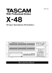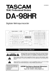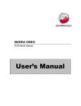
1
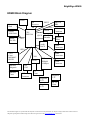
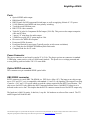
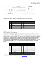
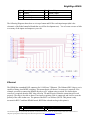
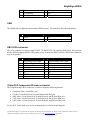
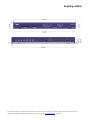
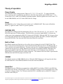
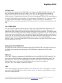
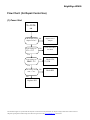
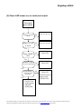
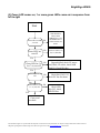
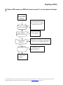
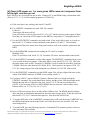
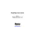
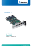
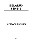
Roku BrightSign HD600
Hardware Guide
PCBA: Rev C & D
Version: 2.1
Palo Alto, CA, USA
1
Table of Contents
OVERVIEW ..................................................................................................................................... 3
HD600 BLOCK DIAGRAM ............................................................................................................. 4
PORTS .......................................................................................................................................... 5
POWER CONNECTOR ..................................................................................................................... 5
OPTICAL SPDIF CONNECTOR ......................................................................................................... 5
DB9 RS232 CONNECTOR .............................................................................................................. 5
DB25 SWITCH/LED CONNECTOR ................................................................................................... 6
ETHERNET .................................................................................................................................... 7
USB ............................................................................................................................................. 8
DB15 VGA CONNECTOR................................................................................................................ 8
TRIPLE RCA COMPONENT HD VIDEO CONNECTOR .......................................................................... 8
1/8” AUDIO CONNECTORS .............................................................................................................. 9
MECHANICAL............................................................................................................................... 10
THEORY OF OPERATION ........................................................................................................... 12
POWER SUPPLY .......................................................................................................................... 12
RESET ........................................................................................................................................ 12
PNX1500 CPU........................................................................................................................... 12
BUILT IN FLASH............................................................................................................................ 12
SDRAM ..................................................................................................................................... 12
SERIAL PORT .............................................................................................................................. 12
VIDEO ENCODER AND FILTER ....................................................................................................... 13
AUDIO OUTPUTS .......................................................................................................................... 13
SPDIF OUTPUT ........................................................................................................................... 13
ON BOARD LEDS ........................................................................................................................ 13
ON BOARD SWITCH ..................................................................................................................... 13
IR RECEIVER ............................................................................................................................... 13
CF FLASH SLOT ........................................................................................................................... 14
4 IN 1 FLASH SLOT....................................................................................................................... 14
OPTIONAL BUILT IN NAND FLASH ................................................................................................. 14
ETHERNET .................................................................................................................................. 14
USB ........................................................................................................................................... 14
FLOW CHART: (FOR REPAIR CENTER USE) ........................................................................... 15
(1) POWER START ....................................................................................................................... 15
(2) POWER LED COMES ON, NO SERIAL PORT OUTPUT................................................................... 16
(2) POWER LED COMES ON, 1 OR MORE GREEN LEDS COME ON IN SEQUENCE FROM LEFT TO RIGHT 17
(3) POWER LED COMES ON, RED LED COMES ON PLUS 1 OR MORE GREEN LED STAYS LIT. ............. 18
2
BrightSign HD600
Overview
This hardware reference manual specifies the hardware interfaces on the HD600, as well as providing a
guide to troubleshoot the hardware of the HD600 for in-field service. This manual will not describe any
software functions.
The BrightSign HD600 is a device that can be used to drive a variety of HDTV and computer monitors
for digital sign and kiosk applications. As well as driving the Video Display, the HD600 has many
different control interfaces built in to allow the sign to be controlled.
This information applies to a product under development. Its characteristics and specifications are subject to change without notice. Roku assumes no
obligation regarding future manufacturing unless otherwise agreed to in writing. www.rokulabs.com © Roku 2006
BrightSign HD600
HD600 Block Diagram
LEDs
Boot
flash
IR
CPU
PNX1500
DB25 &
DB9
GPIO
switch
NAND
/NOR flash
Buffer
For XD
RS232
IR
Receiver
QVCP
XIO
SAA7105
Encoder
3
Audio
DACS
RGB/VGA
Connector
Active
Filter
Video
Connectors
GPIO
4-in-1
Conn.
MS/MMC/
SD/XD
Ethernet
Magnetic
Ethernet
Conn.
Audio
Connectors
XIO
buffer
DDR
SDRAM
64 MByte
SPDIF
Connector
ISP
1582
USB
Connector
CF
Conn.
Regulator
2.5V
Regulator
1.2V
Regulator
3.3V
DC 5V
Conn.
This information applies to a product under development. Its characteristics and specifications are subject to change without notice. Roku assumes no
obligation regarding future manufacturing unless otherwise agreed to in writing. www.rokulabs.com © Roku 2006
BrightSign HD600
Ports
•
•
•
•
•
•
•
•
•
•
•
•
•
•
Optical SPDIF audio output.
DB9 Male RS232.
DB25 Female for LED output and Switch input, as well as supplying 100mA of 3.3V power.
10/100 Ethernet Auto-MDIX and Auto-polarity switching.
Two high speed USB host ports.
DB15 VGA video connector.
Triple RCA jacks for Component Hi-Def output (Y-Pr-Pb). This port can also output composite
video and S-Video.
3 stereo 1/8” mini plugs for audio output
2.5MM Power plug for 5V power input at 2.8A.
IR receiver for 38KHz IR reception.
Front panel LEDs for status.
Front panel Switch for user input (Typically used to switch screen resolutions)
4 in 1 flash slot for SD/MMC/XD/MemoryStick flash cards.
Compact Flash slot for CF cards.
Power Connector
The power connector on our board is rated at 5V @ 2.8A. The plug to go into our connector is standard
5.5MM plug, center positive, with a 2.1MM center pin hole. The power is over voltage protected and
reverse polarity protected with a 5W 5.6V zener diode.
Optical SPDIF connector
This connector accepts a standard SPDIF optical cable.
DB9 RS232 connector
RS232 connector is a male DB9. The HD600 is a DTE device (like a PC). The input to our chip accepts
up to +25V and -25V, so it is compatible with standard +12 and -12 volt signaling. The output of our chip
is rated at +5.4V and -5.4V typical which exceeds the voltage required by the RS232 specification. The
chip we use for RS232 only enables the RS232 transmit function when a valid RS232 voltage level is
detected on the receive line. This implies that the RS232 connector cannot be used for RS232 output only.
The baud rate is 9600, No parity, 8 data bits, 1 stop bit. No hardware or software flow control. The TX
and RX signal will look like this:
This information applies to a product under development. Its characteristics and specifications are subject to change without notice. Roku assumes no
obligation regarding future manufacturing unless otherwise agreed to in writing. www.rokulabs.com © Roku 2006
BrightSign HD600
The pinout of the DB9 on the REVB HD600 board is as follows (NC=No Connect):
pin Description
1
NC
3
Transmit data out of
HD600
5
Ground
7
NC
9
NC
pin Description
2
Receive data into HD600
4
NC
6
8
NC
NC
DB25 Switch/LED connector
The Switch/Led connector is a DB25 Female. This connector is used to allow the HD600 to control
external LEDs or other devices requirind 15mA of current or less. Connect the LED outputs to the LED
ANODE and connect LED CATHODE to ground. If you want to connect up some other device then the
output is capable of sourcing or sinking up to 24mA at 3.3V, but we do have a series resistor of 100 Ohms
in each line. This connector also allows connecting up external contact closures to ground. In order to
connect a switch, connect one side of the switch to the switch input, and connect the other side of the
switch to one of the ground pins on the DB25 connector. Finally the connector can also supply 3.3V at up
to 100mA to an external device. The 3.3V output is polyfuse protected. The DB25 has the following
pinout:
pin
1
3
5
7
9
11
13
15
17
Description
LED 5 output
LED 2 output
Button 11 input
Ground
Button 5 input
Ground
+3.3V output
LED 3 output
Ground
pin
2
4
6
8
10
12
14
16
18
Description
Ground
LED 0 output
Button 9 input
Button 6 input
Button 3 input
Button 1 input
LED 4 output
LED 1 output
Button 10 input
This information applies to a product under development. Its characteristics and specifications are subject to change without notice. Roku assumes no
obligation regarding future manufacturing unless otherwise agreed to in writing. www.rokulabs.com © Roku 2006
BrightSign HD600
19
21
23
25
Button 8 input
Ground
Button 2 input
Button 0 input
20
22
24
Button 7 input
Button 4 input
Ground
The following Diagram shows how to wire up a button and LED to each input/output (this is the
schematic of the Roku button/led board that we sell for development use). You of course can use as little
or as many of the inputs and outputs as you wish.
Ethernet
The HD600 has a standard RJ45 connector for 10/100 base T Ethernet. The Ethernet PHY chip we use is
capable of doing Auto-MDIX switching. This means that it will detect if a crossover is required, if for
example you tried to connect the HD600 directly to a PC without using a switch. If it detects that a
crossover is required, then the PHY chip will swap TX and RX pairs so that the connection will work
properly. The chip is also able to detect if an incorrect polarity cable is connected, and it will reverse the
polarity of the cable in that case. The pinout of the RJ45 is as follows (NOTE: This pinout is only
accurate for REVC and later HD600 boards, REVB has a hardware bug in this pinout):
pin Description
1
TX+
pin Description
2
TX-
This information applies to a product under development. Its characteristics and specifications are subject to change without notice. Roku assumes no
obligation regarding future manufacturing unless otherwise agreed to in writing. www.rokulabs.com © Roku 2006
BrightSign HD600
3
5
7
RX+
RC to ground
RC to ground
4
6
8
RC to ground
RX
RC to ground
USB
The HD600 has two high speed (400 mbit) USB host ports. The ports have the following pinout:
pin Description
1
VBUS
3
D+
pin Description
2
D4
Ground
DB15 VGA connector
The VGA connector is a able to output 1280 X 720 and 1024 X 768 computer RGB video. The connector
has the following pinout (NOTE: This pinout is only accurate for REVC and later. REVB has a hardware
bug on the pinout):
pin
1
3
5
7
9
11
13
15
Description
RED analog video output
BLUE analog video output
Digital ground
Analog ground
NC
NC
HSYNC output
NC
pin
2
4
6
8
10
12
14
Description
GREEN analog video output
NC
Analog ground
Analog ground
Digital ground
NC
VSYNC output
Triple RCA Component HD video connector
The component triple RCA connector is a able to output the following formats:
•
•
•
•
•
Composite video – from Blue jack.
S-Video: Luma from Green jack and Chroma from Red jack
480P video: Y from Green jack, Pr from Red jack, and Pb from Blue jack.
720P video: Y from Green jack, Pr from Red jack, and Pb from Blue jack.
1080i video: Y from Green jack, Pr from Red jack, and Pb from Blue jack.
To use the S-Video mode, you can use an adaptor that is wired as in this diagram:
This information applies to a product under development. Its characteristics and specifications are subject to change without notice. Roku assumes no
obligation regarding future manufacturing unless otherwise agreed to in writing. www.rokulabs.com © Roku 2006
BrightSign HD600
1/8” Audio connectors
The HD600 has three 1/8” female audio connectors. Each connector has a stereo audio signal. The full
scale voltage output of the audio is 3.06V PP, with no load. The minimum load resistance that should be
connected to the audio output is 3K Ohm.
The connectors have the following pinout:
Tip: Left audio
Ring: Right audio
Base: Ground for audio signal
This information applies to a product under development. Its characteristics and specifications are subject to change without notice. Roku assumes no
obligation regarding future manufacturing unless otherwise agreed to in writing. www.rokulabs.com © Roku 2006
BrightSign HD600
Mechanical
This information applies to a product under development. Its characteristics and specifications are subject to change without notice. Roku assumes no
obligation regarding future manufacturing unless otherwise agreed to in writing. www.rokulabs.com © Roku 2006
BrightSign HD600
This information applies to a product under development. Its characteristics and specifications are subject to change without notice. Roku assumes no
obligation regarding future manufacturing unless otherwise agreed to in writing. www.rokulabs.com © Roku 2006
BrightSign HD600
Theory of operation
Power Supply
The HD600 has a four voltages present. These are 5V, 3.3V, 2.5V, and 1.2V. 5V comes in from the
power connector and is used directly for USB, the video filter chip, and the optical SPDIF chip. 3.3V is
created from 5V by a AMC2596-ADJDDF switching regulator. Similar regulators are used to create 2.5V
for the DDR SDRAM, and 1.2V for the PNX1500 core voltage.
Reset
The HD600 has a Low Voltage Reset circuit made up of a ADM809SART. This circuit will hold the
RESET_L signal low until a valid 3.3V power is present.
PNX1500 CPU
The HD600 has a Philips PNX1500 Multimedia CPU in it. This CPU runs on 3.3V, 2.5V, and 1.2V. The
PNX1500 runs from a 27MHz oscillator. The PNX1500 is reset by the signal RESET_L from the low
voltage reset circuit going into the POR_IN_N pin on the PNX1500. When the POR_IN_N pin goes from
low to high, then the PNX1500 will look at the bootstrap pins GPIO0 and GPIO1, which are both pulled
low on the PNX1500. This forces the PNX1500 to boot from IIC serial flash.
Built in Flash
The HD600 contains two flash devices. One of the devices is denoted to be the IIC BOOT flash. This
flash is write protected from the factory and it contains the MAC address for the 10/100 Ethernet chip, as
well as the boot code and the SRB bytes. The boot code in the IIC serial flash instructs the PNX1500 to
continue the boot process by reading additional code from the on board RUN MODE NOR flash. This
flash can be updated in the field, either from on the flash slots or 10/100 Ethernet. Part of the RUN
MODE flash is also used to hold non-volatile parameters. The contents of the boot flash is copied into the
SDRAM, then the PNX1500 jumps to the boot code.
SDRAM
The HD600 contains two DDR SDRAM devices. When the PNX1500 boots, it will copy the code from
the NOR flash device into SDRAM, and then execute the code from SDRAM.
Serial Port
The HD600 uses two GPIO lines to communicate with the RS232 level shifter. GPIO58 is the RXD line,
and GPIO0 is the txd line. The MAX3221 creates valid RS232 voltage levels for the transmit pin by using
a capacitive voltage switcher. The TXD pin on the MAX3221 is disabled until a valid RS232 voltage is
detected on the RXD pin.
This information applies to a product under development. Its characteristics and specifications are subject to change without notice. Roku assumes no
obligation regarding future manufacturing unless otherwise agreed to in writing. www.rokulabs.com © Roku 2006
BrightSign HD600
Video Encoder and Filter
The PNX1500 streams decoded video out of the VDO port using a double data rate clock. In other words,
12 bits of video data is clocked out of the PNX1500 on the rising edge of the VDO_CLK signal, and on
the dalling edge as well. This allows the PNX1500 to output 24 bits of data at a 74.25MHz rate, using
only a single 74.25MHz clock and 12 data lines. The SAA7105 video encoder takes the VDO data in and
sends the data straight to the video DACs in HD mode. In Composite or S-Video mode then the encoder
creates the proper signals in internal blocks for each type of video. The SAA7105 also has an internal
SYNC engine that is only used in HD mode to add video sync to the GREEN component signal. In VGA
mode, the sync signals from the PNX1500 and are passed through the SAA7105. The SAA7105 mode is
controlled by IIC from the PNX1500. Analog video comes out of the SAA7105 and is connected to the
Fairchild FMS6346MTC20 video filter chip. This chip has a programmable cutoff frequency of either
8MHz or 32MHz. When the HD600 is outputting Composite or S-Video, the filter chip is in 8MHz cutoff
mode. When outputting all other modes, then the filter is in 32MHz cutoff mode. Since the video filter
has a low impedance output, we can drive both VGA and COMPONENT 75Ohm terminated cables at the
same time with no degradation (with the same signal).
Audio outputs
The HD600 has three audio DAC devices, which are Philips UDA1334. These devices take in digital
audio signals from the PNX1500 for AO_SCK, AO_WS, and AO_SDX. The AO_WS signal is the
framing signal for the audio, running at the frame rate of the audio source. The frame rate is usually either
44.1KHz or 48KHz. AO_SCK signal is typically 64 times higher than AO_WS, The PNX1500 The
UDA1334 device has a built in PLL so it can generate the internal 4X oversampling clock from the
A)_SCK. The output of the UDA1334 device is left and right analog audio.
SPDIF output
The PNX1500 can generate the SPDIF audio signal internally. This signal, called SPDIF_OPT is
connected to a OPTICAL SPDIF transmitter chip on the board.
On Board LEDs
There are 18 on board LEDs. One of the LEDs is red in color and is designated to be the BUSY LED. Six
of the LEDs are the resolution LEDs, intended to tell the user what resolution the HD600 is currently
outputting. The other LEDs are intended to tell the user which output connectors are active. All the LEDs
are controlled by a set of 3 74HC574 latches. Data is latched into the latches under GPIO control.
On Board Switch
The on board switch is connected to a GPIO55. There is a pullup on the button so that GPIO55 is high
normally, and it is pulled low when the button is pressed.
IR Receiver
The IR receiver receives a 38KHz IR signal. The IR signal is filtered and demodulated and then sent into
the PNX1500 on GPIO60. The signal is called IR_DAT on the schematic.
This information applies to a product under development. Its characteristics and specifications are subject to change without notice. Roku assumes no
obligation regarding future manufacturing unless otherwise agreed to in writing. www.rokulabs.com © Roku 2006
BrightSign HD600
CF flash slot
The CF flash slot is connected up in TRUE IDE mode, and it uses the PNX1500 IDE mode on the XIO
bus. The chip select for the CF slot is XIO_SEL1. two 74LVC245 bidirectional buffers isolate the
databus of the CF from the XIO databus, so that the CF card can be hot plugged. A 74LVC244 chip
buffers the other CF signals, again so that the CF card can be hot plugged. The PNX1500 won’t attempt to
access the CF slot unless it first detects that a CF card is present. The signal CF_CD_L goes low when a
CF card is inserted. This signal is connected to GPIO52. Power to the CF slot is controlled by a
MOSFET, and it is not turned on until the PNX1500 detects that a CF card has been inserted into the CF
slot.
4 in 1 Flash Slot
The 4 in 1 flash slot supports 4 different formats of flash cards: MMC/SD/XD/MS. MMC/SD use the
same physical pins on the connector. Each of the 3 physical formats have its own card detect pin
connected to GPIO, so that the PNX1500 can detect which kind of card is connected. The MMC/SD/MS
formats are 4 bit wide serial formats and the HD600 uses GPIO to communicate with the 4 cards. The XD
format is the same as NAND flash, and so the built in PNX1500 NAND flash controller on the XIO bus is
used for XD. The XD interface has buffers to isolate the databus and control signals from the XIO bus so
that the XD card can be hot plugged and un-plugged. Power to the 4 in 1 slot is controlled by a
MOSFET, and it is not turned on until the PNX1500 detects that one of the MMC/SD/XD/MS cards has
been inserted into the 4 in 1 slot.
Optional built in NAND flash
The HD600 has a spot on the board to support loading a built in NAND flash. This could be used to give
the HD600 a large amount of on board storage. The NAND flash is connected to the XIO on the
PNX1500.
Ethernet
10/100 Base T Ethernet is implemented on the HD600 by a Davicom DM9161AE PHY controller. This
device takes the PNX1500 Ethernet signals and converts them to the differential Ethernet signals. The
PHY chip is also connected to an on-board Ethernet magnetic and a RJ45 for cable termination. The
DM9161 chip is able to signal to the PNX1500 that its state has changed by toggling the
ETH_PHY_INT_L line, which is connected to GPIO11.
USB
USB is implemented by a PCI ISP1562 USB dual host controller chip. There is also a dual over-current
protected switch TPS2042BD device, which is used to turn on and off power to the USB device, and to
detect over-current situations.
This information applies to a product under development. Its characteristics and specifications are subject to change without notice. Roku assumes no
obligation regarding future manufacturing unless otherwise agreed to in writing. www.rokulabs.com © Roku 2006
BrightSign HD600
Flow Chart: (for Repair Center Use)
(1) Power Start
No LEDs
on
Is the Output power
adapter 5V DC?
No
Replace Power
Adapter
Is the Voltage of
No
Check D22 & D23
for shorts
L76 = 5V?
Yes
Is the Voltage of
No
Check U30,
L73, U20
No
Check RP5
TP43 3.3V?
Yes
Is the Voltage across
D23 ~= 2V?
Yes
Replace D23
This information applies to a product under development. Its characteristics and specifications are subject to change without notice. Roku assumes no
obligation regarding future manufacturing unless otherwise agreed to in writing. www.rokulabs.com © Roku 2006
BrightSign HD600
(2) Power LED comes on, no serial port output
No serial
port output
Is there 2.5V DC at
TP19?
No
Check U22, D11, L55
Is there 1.2V DC
at TP42?
No
Check U27, L59, D18
No
Check U26
Is RESET_L high at No
R197 after powerup?
Check U36
Yes
Is there 27MHz at
R50?
Yes
Yes
Is SYS_RESET_L
high at R7 after
powerup?
Yes
No
Check U23,
Check I2C bus for
shorts, Check
PNX1500 U18
Check U9 for
good program
and good
solder joints,
This information applies to a product under development. Its characteristics and specifications are subject to change without notice. Roku assumes no
obligation regarding future manufacturing unless otherwise agreed to in writing. www.rokulabs.com © Roku 2006
BrightSign HD600
(2) Power LED comes on, 1 or more green LEDs come on in sequence from
left to right
Start
Green LED1 or LED2 No
, rest off?
Green LED3 on,
rest off?
No
NOR flash boot
failed, Check
SDRAM U19, U35
and NOR flash U9.
Check XIO bus for
shorts.
Check CF socket, U3,
U4, U6, XIO bus
Yes
Green LED4 or 5 or No
6 or 7 on, rest off?
Upgrade failed, check CF source
card, check CF socket, check NOR
flash U9, Check XIO bus
Yes
Green LED8 on, rest
off?
No
Check SAA7105 U25,
check I2C bus for shorts
Yes
Green LED9 or 10 or
11 on, rest off?
Yes
No
Check USB
chip U12, check
XIO/PCI bus
Goto serial
port check
This information applies to a product under development. Its characteristics and specifications are subject to change without notice. Roku assumes no
obligation regarding future manufacturing unless otherwise agreed to in writing. www.rokulabs.com © Roku 2006
BrightSign HD600
(3) Power LED comes on, RED led comes on plus 1 or more green led stays
lit.
Start, RED
led on
NOR flash read failed, NOR
flash U9 contents. Try updating
NOR flash with CF card.
Green LED1 or LED2 No
or LED3 or LED4 on?
No
Green LED5 or
LED6 or LED7 on?
Check CF socket, U3,
U4, U6, XIO bus
Yes
Green LED8 or
LED9 on?
No
NOR flash read failed. Try updating NOR
flash with CF card. failed. Check U9.
No
NOR flash write
failed. Check U9.
Yes
Green LED10 on?
Yes
Goto serial
port check
This information applies to a product under development. Its characteristics and specifications are subject to change without notice. Roku assumes no
obligation regarding future manufacturing unless otherwise agreed to in writing. www.rokulabs.com © Roku 2006
BrightSign HD600
(4) Power LED comes on, 1 or more green LEDs come on in sequence from
left to right, and then go out.
Red LED stays out. Serial port tests are in order. Connect a PC to the HD600 using a null modem cable
(Wire up 2-3, 3-2, 5-5). Set the terminal program to 115,200 N,8,1.
A) If the serial port is not working, then check U2 and P2.
B) Use LEDTEST command to test each LED. For example:
Ledtest 0 1
Turns on the left most (red) led
If any LED fails to come on, then check U15, U16, U17 and the resistors on the outputs of these.
Note that you can test the 6 LED outputs on the DB25 by using ledtest 17 1 through ledtest 24 1
C) Use the SWITCHTEST command to test each switch. If any switch fails to read, or is stuck on,
then check U5, U7 and the resistors and beads on the inputs to U5 and U7. The switchtest
command will show the status of the front panel switch as well as the switches connected to the
DB25.
D) Use the MEDIADIR command to test reading the CF card. For example:
Mediadir ATA:/
If the CF card fails to read, check U3, U4, U6 and the CF socket, and associated resistor packs.
E) Use the SINETEST command to test the audio outputs. The SINETEST command will put a sine
wave on each of the stereo outputs. If the audio fails to work, check U28, U31, U32. Check for
the audio master clock on R25, should be 11.288MHz. Check for audio bit clock R26, should be
2.82MHz. Check for audio data on R159, R160, R161. Check passives on outputs of U28, U31,
U32. The voltage output of the audio during this test (fullscale) is 3.06V PP, with no load.
F) Use the SPDIFTEST command to test the SPDIF output. This will put a digital sinewave on the
output of the SPDIF connector. If SPDIF is not working, check U1.
G) If you have a REVC or newer HD600, Connect a Ethernet cable to a switch, and run the
ETHTEST command. The switch should show link on, and the yellow LED should light on the
HD600 showing link on. If this does not work, check U14, T1, P8 and associated passives.
(NOTE: If you are using a REVA or REVB HD600 then you must use a mirror image wired
Ethernet cable (1-8, 2-7,3-6,4-5,5-4,6-3,7-2,8-1)
H) Insert a USB mass storage device in either of the USB host slots. The HD600 should configure
these and print out information automatically about the mass storage device. If this does not work,
then check U12, U34, P7, and associated passives. Also check the XIO/PCI bus.
I) To test the SDIO slot, us the CARDTEST command. Insert a SD card, then issue CARDTEST and
the HD600 should print out the model of the card. If this does not work, check P6, U18, and
associated passives.
J) To test the RGB, issue the following sequence of commands (This assumes you have some test
video and image files available):
This information applies to a product under development. Its characteristics and specifications are subject to change without notice. Roku assumes no
obligation regarding future manufacturing unless otherwise agreed to in writing. www.rokulabs.com © Roku 2006
BrightSign HD600
VIDEOMODE 1024x768x60p
VIDEOTEST ATA:/true.vob
(You can use your own VOB file or MPEG2 file for this test, on the CF card)
If the RGB video fails to play, check the following: U25, U24, U21, P9. While playing RGB in
1024x768 mode, the following signals should be present:
•Videoclock at pin 20 of U25 should be 65MHz.
•HSVGC and HSYNC should have 48.35KHz
•VSVGC and VSYNC should have 60Hz
K) To test the Component video, issue the following sequence of commands (This assumes you have
some test video and image files available):
VIDEOMODE 1920x1080x60i
VIDEOTEST ATA:/true.vob
(You can use your own VOB file or MPEG2 file for this test, on the CF card)
If the Component video fails to play, check the following: U25, U24, U21, P9. While playing
component video in 1920x1080x60i mode, the following signals should be present:
•Videoclock at pin 20 of U25 should be 74.25MHz.
•HSVGC and HSYNC should have 31.47KHz
•VSVGC and VSYNC should have 59.95Hz
This information applies to a product under development. Its characteristics and specifications are subject to change without notice. Roku assumes no
obligation regarding future manufacturing unless otherwise agreed to in writing. www.rokulabs.com © Roku 2006