1
Roku BrightSign HD2000
Hardware Guide
PCBA: Rev C
Version: 1.3
Palo Alto, CA, USA
1
Table of Contents
OVERVIEW ..................................................................................................................................... 3
HD2000 BLOCK DIAGRAM ........................................................................................................... 4
PORTS .......................................................................................................................................... 5
POWER CONNECTOR ..................................................................................................................... 5
OPTICAL SPDIF CONNECTOR ......................................................................................................... 5
DB9 RS232 CONNECTOR .............................................................................................................. 5
DB25 SWITCH/LED CONNECTOR ................................................................................................... 6
ETHERNET .................................................................................................................................... 7
USB ............................................................................................................................................. 8
DB15 VGA CONNECTOR................................................................................................................ 8
TRIPLE RCA COMPONENT HD VIDEO CONNECTOR .......................................................................... 8
1/8” AUDIO CONNECTORS .............................................................................................................. 8
MECHANICAL............................................................................................................................... 11
THEORY OF OPERATION ........................................................................................................... 12
POWER SUPPLY .......................................................................................................................... 12
RESET ........................................................................................................................................ 12
PNX8950 CPU........................................................................................................................... 12
BUILT IN FLASH............................................................................................................................ 12
SDRAM ..................................................................................................................................... 12
SERIAL PORT .............................................................................................................................. 12
VIDEO ENCODER AND FILTER ....................................................................................................... 13
AUDIO OUTPUTS .......................................................................................................................... 13
SPDIF OUTPUT ........................................................................................................................... 13
ON BOARD LEDS ........................................................................................................................ 13
ON BOARD SWITCH ..................................................................................................................... 14
IR RECEIVER ............................................................................................................................... 14
CF FLASH SLOT ........................................................................................................................... 14
4 IN 1 FLASH SLOT....................................................................................................................... 14
OPTIONAL BUILT IN NAND FLASH ................................................................................................. 14
ETHERNET .................................................................................................................................. 14
USB ........................................................................................................................................... 14
FLOW CHART: (FOR REPAIR CENTER USE) ........................................................................... 15
(1) POWER START ....................................................................................................................... 15
(2) POWER LED COMES ON, NO SERIAL PORT OUTPUT................................................................... 16
(2) POWER LED COMES ON, 1 OR MORE GREEN LEDS COME ON IN SEQUENCE FROM LEFT TO RIGHT
................................................................................................... ERROR! BOOKMARK NOT DEFINED.
(3) POWER LED COMES ON, RED LED COMES ON PLUS 1 OR MORE GREEN LED STAYS LIT. ..... ERROR!
BOOKMARK NOT DEFINED.
2
BrightSign HD2000
Overview
This hardware reference manual specifies the hardware interfaces on the HD2000, as well as providing a
guide to troubleshoot the hardware of the HD2000 for in-field service. This manual will not describe any
software functions.
The BrightSign HD2000 is a device that can be used to drive a variety of HDTV and computer monitors
for digital sign and kiosk applications. As well as driving the Video Display, the HD2000 has many
different control interfaces built in to allow the sign to be controlled. The Brightsign HD2000 is
differentiated from the HD2000 in that the HD2000 can decode MPEG2 HD video files and it has HDMI
output, as well as additional IO interfaces.
This information applies to a product under development. Its characteristics and specifications are subject to change without notice. Roku assumes no
obligation regarding future manufacturing unless otherwise agreed to in writing. www.rokulabs.com © Roku 2006
BrightSign HD2000
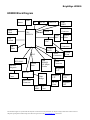
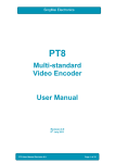
HD2000 Block Diagram
LEDs
IR
Button
Boot
flash
ETAP
MAX232
RGB/VGA
Connector
switch
CPU
PNX8950
DB9
DB25
Video
DAC
Dip
switch
Active
Filter
HDMI
ENC.
Video
Connectors
2K
flash
3 Audio
DACS
PCI
Realtec
RTL8100C
Ethernet
Conn.
DDR
SDRAM
256 MByte
2 banks
NAND
flash
Ethernet
Magnetic
HDMI
Conn.
Audio
Connectors
SPDIF
Connector
Regulator
2.5V
ISP1563
USB to
Flash
Bridge
Dual USB
Connector
SD/
MMC
Regulator
3.3V
Regulator
1.25V
DC 5V
Conn.
Regulator
1.8V
CF
Conn.
This information applies to a product under development. Its characteristics and specifications are subject to change without notice. Roku assumes no
obligation regarding future manufacturing unless otherwise agreed to in writing. www.rokulabs.com © Roku 2006
BrightSign HD2000
Ports
On back of the unit:
• Power plug for 5V power input at 3A
• 3 stereo 1/8” mini plugs for audio output
• DB15 VGA video connector.
• Triple RCA jacks for Component Hi-Def output (Y-Pr-Pb). This port can also output composite
video and S-Video.
• HDMI connector
• Two high speed USB host ports.
• 10/100 Ethernet jack
• DB25 Female for LED output and Switch input, as well as supplying 100mA of 3.3V power.
• DB9 Male RS232.
• 1/8” ETAP serial connector (0-5V serial)
• Optical SPDIF audio output.
• 8 position dip switch
On front of the unit:
• Power LED
• IR receiver for 38KHz IR reception.
• Front panel LEDs for status.
• Front panel Switch for user input (Typically used to switch screen resolutions)
• SD/MMC flash card slot
• Compact Flash slot for CF cards.
Power Connector
The power connector on our board is rated at 5V @ 3A. The plug to go into our connector is standard
5.5MM plug, center positive, with a 1.65MM center pin hole. The power is over voltage protected and
reverse polarity protected with two 5W 5.6V zener diodes.
Optical SPDIF connector
This connector accepts a standard SPDIF optical cable.
DB9 RS232 connector
RS232 connector is a male DB9. The HD2000 is a DTE device (like a PC). The input to our chip accepts
up to +25V and -25V, so it is compatible with standard +12 and -12 volt signaling. The output of our chip
is rated at +5.4V and -5.4V typical which exceeds the voltage required by the RS232 specification. The
chip we use for RS232 only enables the RS232 transmit function when a valid RS232 voltage level is
detected on the receive line. This implies that the RS232 connector cannot be used for RS232 output only.
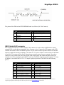
The baud rate is 9600, No parity, 8 data bits, 1 stop bit. No hardware or software flow control. The TX
and RX signal will look like this:
This information applies to a product under development. Its characteristics and specifications are subject to change without notice. Roku assumes no
obligation regarding future manufacturing unless otherwise agreed to in writing. www.rokulabs.com © Roku 2006
BrightSign HD2000
The pinout of the DB9 on the REVB HD2000 board is as follows (NC=No Connect):
pin Description
1
NC
3
Transmit data out of
HD2000
5
Ground
7
RTS
9
NC
pin Description
2
Receive data into HD2000
4
Available 5V @ 250mA
6
8
NC
CTS
DB25 Switch/LED connector
The Switch/Led connector is a DB25 Female. This connector is used to allow the HD2000 to control
external LEDs or other devices requirind 15mA of current or less. Connect the LED outputs to the LED
ANODE and connect LED CATHODE to ground. If you want to connect up some other device then the
output is capable of sourcing or sinking up to 24mA at 3.3V, but we do have a series resistor of 100 Ohms
in each line. This connector also allows connecting up external contact closures to ground. In order to
connect a switch, connect one side of the switch to the switch input, and connect the other side of the
switch to one of the ground pins on the DB25 connector. Finally the connector can also supply 3.3V at up
to 100mA to an external device. The 3.3V output is polyfuse protected. The DB25 has the following
pinout:
pin
1
3
5
7
9
11
13
15
17
Description
LED 5 output
LED 2 output
Button 11 input
Ground
Button 5 input
Ground
+3.3V output @ 100mA
LED 3 output
Ground
pin
2
4
6
8
10
12
14
16
18
Description
Ground
LED 0 output
Button 9 input
Button 6 input
Button 3 input
Button 1 input
LED 4 output
LED 1 output
Button 10 input
This information applies to a product under development. Its characteristics and specifications are subject to change without notice. Roku assumes no
obligation regarding future manufacturing unless otherwise agreed to in writing. www.rokulabs.com © Roku 2006
BrightSign HD2000
19
21
23
25
Button 8 input
Ground
Button 2 input
Button 0 input
20
22
24
Button 7 input
Button 4 input
Ground
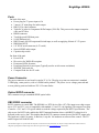
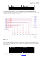
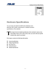
The following Diagram shows how to wire up a button and LED to each input/output (this is the
schematic of the Roku button/led board that we sell for development use). You of course can use as little
or as many of the inputs and outputs as you wish.
Ethernet
The HD2000 has a standard RJ45 connector for 10/100 base T Ethernet. The pinout of the RJ45 is as
follows (NOTE: This pinout is only accurate for REVC and later HD2000 boards, REVB has a hardware
bug in this pinout):
pin
1
3
5
7
Description
TX+
RX+
RC to ground
RC to ground
pin
2
4
6
8
Description
TXRC to ground
RX
RC to ground
This information applies to a product under development. Its characteristics and specifications are subject to change without notice. Roku assumes no
obligation regarding future manufacturing unless otherwise agreed to in writing. www.rokulabs.com © Roku 2006
BrightSign HD2000
USB
The HD2000 has two high speed (400 mbit) USB host ports. The ports have the following pinout:
pin Description
1
VBUS
3
D+
pin Description
2
D4
Ground
DB15 VGA connector
The VGA connector is a able to output 1280 X 720 and 1024 X 768 computer RGB video. The connector
has the following pinout (NOTE: This pinout is only accurate for REVC and later. REVB has a hardware
bug on the pinout):
pin
1
3
5
7
9
11
13
15
Description
RED analog video output
BLUE analog video output
Digital ground
Analog ground
+5V DDC supply (REVC
only)
NC
HSYNC output
DDC SCL (REVC only)
pin
2
4
6
8
10
Description
GREEN analog video output
NC
Analog ground
Analog ground
Digital ground
12
14
DDC SDA (REVC only)
VSYNC output
Triple RCA Component HD video connector
The component triple RCA connector is a able to output the following formats:
•
•
•
480P video: Y from Green jack, Pr from Red jack, and Pb from Blue jack.
720P video: Y from Green jack, Pr from Red jack, and Pb from Blue jack.
1080i video: Y from Green jack, Pr from Red jack, and Pb from Blue jack.
1/8” Audio connectors
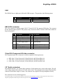
The HD2000 has three 1/8” female audio connectors. Each connector has a stereo audio signal. The full
scale voltage output of the audio is 3.06V PP, with no load. The minimum load resistance that should be
connected to the audio output is 5 Ohms. The connectors are capable of driving headphones directly.
The connectors have the following pinout:
This information applies to a product under development. Its characteristics and specifications are subject to change without notice. Roku assumes no
obligation regarding future manufacturing unless otherwise agreed to in writing. www.rokulabs.com © Roku 2006
BrightSign HD2000
Tip: Left audio
Ring: Right audio
Base: Ground for audio signal
HDMI connector
The HDMI connector is used to send digital video and audio to HDMI enabled sink devices. This is the
pinout of the HDMI connector:
pin
1
3
5
7
9
11
13
15
17
19
Description
TX2p
TX2n
Ground
TX0p
TX0n
Ground
CEC
DDC SCL
Ground
HPD (Hot Plug Detect)
pin
2
4
6
8
10
12
14
16
18
20
Description
Ground
TX1p
TX1n
Ground
TXCp
TXCn
NC
DDC SDA
+5V DDC
Ground
ETAP connector
The HD2000 has a single 1/8” female connector for ETAP. This port is used to communicate with devices
that require 0 and 5V serial signaling.
This connector has the following pinout:
Tip: Receive data
Ring: Transmit data
Base: Ground
This information applies to a product under development. Its characteristics and specifications are subject to change without notice. Roku assumes no
obligation regarding future manufacturing unless otherwise agreed to in writing. www.rokulabs.com © Roku 2006
BrightSign HD2000
Power usage
The power supply on the HD2000 is a 15W 5V @ 3A power supply. The HD2000 will use
approximately 2.1A of power when playing a 720p or 1080i MPEG2 HD source file. This implies that
there is 900mA of additional available power that can be used by peripherals connected to the HD2000.
The user should not connect up any combination of peripherals that will exceed 900mA draw. If more
than 900mA is drawn, then the external power supply will shut down due to overcurrent conditions. The
unit will not be damaged, but it may cause the unit to reboot or to not operate properly until the overload
is removed.
This 900mA can be shared any way you like on the following connectors.
USB1 – 500mA max
USB2 – 500mA max
DB9 5V – 250mA
DB25 3.3V – 100mA
HDMI 5V – 55mA max
Each of 6 LED outputs on DB25 – up to 24mA each
Audio 1, 2, 3 – 200mA max (i.e. if you connect up 5Ohm headphones, then each audio connector can
output up to 200mA RMS)
This information applies to a product under development. Its characteristics and specifications are subject to change without notice. Roku assumes no
obligation regarding future manufacturing unless otherwise agreed to in writing. www.rokulabs.com © Roku 2006
BrightSign HD2000
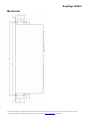
Mechanical
This information applies to a product under development. Its characteristics and specifications are subject to change without notice. Roku assumes no
obligation regarding future manufacturing unless otherwise agreed to in writing. www.rokulabs.com © Roku 2006
BrightSign HD2000
Theory of operation
Power Supply
The HD2000 has a five voltages present. These are 5V, 3.3V, 2.5V, 1.8Vand 1.2V. 5V comes in from the
power connector and is used directly for USB, the video filter chip, the optical SPDIF chip, and the audio
dacs. 3.3V is created from 5V by a AMC2596 switching regulator. Similar regulators are used to create
2.5V for the DDR SDRAM, 1.8V for the HDMI chip, and 1.2V for the PNX8950 core voltage.
Reset
The HD2000 has a Low Voltage Reset circuit made up of a ADM809SAKS. This circuit will hold the
RESET_L signal low until a valid 3.3V power is present.
PNX8950 CPU
The HD2000 has a Philips PNX8950 Multimedia CPU in it. This CPU runs on 3.3V, 2.5V, and 1.2V.
The PNX8950 runs from a 27MHz oscillator. The PNX8950 is reset by the signal RESET_L from the
low voltage reset circuit going into the RESET_IN pin on the PNX8950. When the RESET_IN pin goes
from low to high, then the PNX8950 will look at the bootstrap pins GPIO0-2, which are pulled low on the
PNX8950. This forces the PNX8950 to boot from IIC serial boot flash.
Built in Flash
The HD2000 contains four flash devices. One of the devices is denoted to be the IIC BOOT flash. This
flash is write protected from the factory and it contains the MAC address for the 10/100 Ethernet chip, as
well as the boot code and the SRB bytes. The boot code in the IIC serial flash instructs the PNX8950 to
continue the boot process by reading additional code from the on board NAND flash. This flash can be
updated in the field, either from on the flash slots or 10/100 Ethernet. Part of the NAND flash is also used
to hold non-volatile parameters. The contents of the boot flash is copied into the SDRAM, then the
PNX8950 jumps to the boot code. There is also a serial settings flash that can be used to contain nonvolatile settings. The last flash is the Ethernet flash that is used to configure the Ethernet PHY chip.
SDRAM
The HD2000 contains four DDR SDRAM devices. When the PNX8950 boots, it will copy the code from
the NAND flash device into SDRAM, and then execute the code from SDRAM. The SDRAM runs at
clock rate 200MHz, with data rate 400MHz.
Serial Port
The HD2000 has a built in UART that that communicates with the RS232 level shifter. The MAX232
creates valid RS232 voltage levels for the transmit pin by using a capacitive voltage switcher.
This information applies to a product under development. Its characteristics and specifications are subject to change without notice. Roku assumes no
obligation regarding future manufacturing unless otherwise agreed to in writing. www.rokulabs.com © Roku 2006
BrightSign HD2000
Video Encoder and Filter
The PNX8950 streams decoded video out of the QVCP5L port using single data rate clock. The PNX8511
video encoder takes the QVCP5L data in and sends the data straight to the video DACs in HD mode. The
PNX8511 also has an internal SYNC engine that is only used in HD mode to add video sync to the 3
component signals. In VGA mode, the sync signals from the PNX8950 and are passed through the
PNX8511. The PNX8511 mode is controlled by IIC from the PNX8950. Analog video comes out of the
PNX8511 and is connected to the Analog Devices ADA4412 video filter chip. This chip has a
programmable cutoff frequency of either 8MHz, 16MHz or 32MHz. Since the video filter has a low
impedance output, we can drive both VGA and COMPONENT 75Ohm terminated cables at the same
time with no degradation (with the same signal).
HDMI encoder
The QVCP5L video is also sent over to the TDA9982B HDMI encoder chip, which drives the HDMI data
out of the HD2000. The HDMI chip is also connected to I2S audio and SPDIF audio, so that audio will
be driven out the HDMI connector.
Audio outputs
The HD2000 has three high quality audio DAC devices, which are Wolfson WM8729. These devices take
in digital audio signals from the PNX8950 for I2S audio. The AUD_LRCIN signal is the framing signal
for the audio, running at the frame rate of the audio source. The frame rate is usually either 44.1KHz or
48KHz. AUD_BITCLK signal is typically 64 times higher than AUD_LRCIN. The AUD_MCLK is
usually 4 times faster than the AUD_BITCLK signal. The I2S audio is also routed to the HDMI chip.
The audio output from the Wolfson DAC is sent to TPA0211 high quality high power audio amplifiers.
These amplifiers are capable of driving 5 Ohm headphones directly.
SPDIF output
The PNX8950 can generate the SPDIF audio signal internally. This signal, called SPDIF_OPT is
connected to a OPTICAL SPDIF transmitter chip on the board. The SPDIF signal is also routed to the
HDMI chip.
On Board LEDs
There are 18 on board LEDs. One of the LEDs is red in color and is designated to be the BUSY LED. Six
of the LEDs are the resolution LEDs, intended to tell the user what resolution the HD2000 is currently
outputting. The other LEDs are intended to tell the user which output connectors are active. All the LEDs
are controlled by a set of 3 74HC574 latches. Data is latched into the latches under GPIO control. The far
left green LED is the power LED. The far right RED LED is the flash activity LED, which flashes
anytime the SD or CF is being accessed.
This information applies to a product under development. Its characteristics and specifications are subject to change without notice. Roku assumes no
obligation regarding future manufacturing unless otherwise agreed to in writing. www.rokulabs.com © Roku 2006
BrightSign HD2000
On Board Switch
The on board switch is connected to a GPIO32. There is a pullup on the button so that GPIO32 is high
normally, and it is pulled low when the button is pressed.
IR Receiver
The IR receiver receives a 38KHz IR signal. The IR signal is filtered and demodulated and then sent into
the PNX8950 on GPIO40. The signal is called IR_DAT on the schematic.
CF flash slot
The CF flash slot is connected up to the SMSC USB2777 USB flash controller chip. The USB2777 is
connected to the ISP1563BM PCI to USB bridge chip. The USB2777 won’t attempt to access the CF slot
unless it first detects that a CF card is present. The signal CF_CD1 and CF_CD2 go low when a CF card
is inserted. Power to the CF slot is controlled by a MOSFET, and it is not turned on until the USB2777
detects that a CF card has been inserted into the CF slot.
SD/MMC Flash Slot
The SD/MMC flash slot supports 2 different formats of flash cards: SD & MMC. Power to the SD/MMC
slot is controlled by a the USB2777 directly with a built in MOSFET, and it is not turned on until the
USB2777 detects that one of the SD/MMC cards has been inserted into the slot.
NAND flash
The HD2000 has a build in NAND flash. All the code for the unit is stored on the NAND flash, and it
may also be possible to store some content on the NAND flash. The NAND flash is connected to the
PCI/XIO bus on the PNX8950.
Ethernet
10/100 Base T Ethernet is implemented on the HD2000 by a Realtec RTL8100C PHY controller. This
device takes the PNX8950 Ethernet signals and converts them to the differential Ethernet signals. The
PHY chip is also connected to an on-board Ethernet magnetic and a RJ45 for cable termination. The
DM9161 chip is able to signal to the PNX8950 that its state has changed by toggling the INT_ETH line,
which is connected to GPIO11.
USB
USB is implemented by a PCI ISP1563 USB dual host controller chip. There is also a dual over-current
protected switch TPS2042BD device, which is used to turn on and off power to the USB device, and to
detect over-current situations.
This information applies to a product under development. Its characteristics and specifications are subject to change without notice. Roku assumes no
obligation regarding future manufacturing unless otherwise agreed to in writing. www.rokulabs.com © Roku 2006
BrightSign HD2000
Appendix A
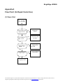
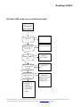
Flow Chart: (for Repair Center Use)
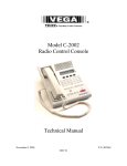
(1) Power Start
No LEDs
on
Is the Output power
adapter 5V DC?
No
Replace Power
Adapter
Is the Voltage of
No
Check D21 & D22
for shorts
L80 = 5V?
Yes
Is the Voltage of
No
Check U34,
L88, D26
No
Check RP15
TP24 3.3V?
Yes
Is the Voltage across
D12 ~= 2V?
Yes
Replace D12
This information applies to a product under development. Its characteristics and specifications are subject to change without notice. Roku assumes no
obligation regarding future manufacturing unless otherwise agreed to in writing. www.rokulabs.com © Roku 2006
BrightSign HD2000
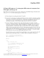
(2) Power LED comes on, no serial port output
No serial
port output
Is there 2.5V DC at
TP19?
No
Check U32, D24, L83
Is there 1.2V DC
at TP20?
No
Check U33, L84, D25
No
Check U1,
Y2, C82, C84,
R63
No
Check U17,
U18
Yes
Is there 27MHz at
TP5?
Yes
Is RESET_L high at
pin 11 of U18 after
powerup?
Yes
Is SYS_RESET_L
high at C83 after
powerup?
Yes
No
Check U13
Check I2C bus for
shorts, Check
PNX8950 U1
Check U13
for good
program and
good solder
joints,
This information applies to a product under development. Its characteristics and specifications are subject to change without notice. Roku assumes no
obligation regarding future manufacturing unless otherwise agreed to in writing. www.rokulabs.com © Roku 2006
BrightSign HD2000
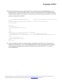
(3) Power LED comes on, 1 or more green LEDs come on in sequence from
left to right, and then go out.
Red LED stays out. Serial port tests are in order. Connect a PC to the HD2000 using a null modem cable
(Wire up 2-3, 3-2, 5-5). Set the terminal program to 38,400 N,8,1.
A) If the serial port is not working, then check U12 and P4.
B) Use the “dir” command to test reading the CF flash card. Use the “dir SD:” command to read from
the SD card. Use “dir USB1:” and “dir USB2:” command to test reading from external USB mass
storage devices. If the CF or SD card fails to read, check U50, Q4 and the CF socket, and
associated resistor packs. If the USB mass storage reads fail, check U40, U42, and P14.
C) Use the “videoplay” command to test the video and audio outputs, for example “videoplay
test.mp3” or “videoplay test.mpg”. If the analog audio fails to work, check U6, U8, U10. Check
for the audio master clock on R10, should be 11.288MHz or 12.288MHz. Check for audio bit
clock R9, should be ¼ of the MCLK. Check for AUD_LRCIN on R11, should be 44.1KHz or
48KHz. Check for audio data on R12, R13, R14. Check passives on outputs of U6, U8, U10. The
voltage output of the audio during this test (fullscale) is 3.06V PP, with no load. Check the audio
amplifiers U2, U3, U5, U7, U9, U11 and associated passives. Check the 5V_ANA power supply.
If the audio fails to come out of the SPDIF output, then check U1 & U4.
Run the following script to test the LEDs. If any LED fails to come on, then check U25, U26, U27
and the resistors on the outputs of these. The DB25 LEDS are controlled by U24 and U26.
port = CreateObject("roMessagePort")
gpio = CreateObject("roGpioControlPort")
gpio.SetPort(port)
led = 0
ls = 0
loop:
msg = wait(100, port)
else if type(msg)="roGpioButton" then
if msg.GetInt() = 12 then end
endif
gpio.SetOutputState(led,ls)
led = led+1
if led > 22 then toggle_led
goto loop
toggle_led:
led = 0
if ls = 0 then ls = 1 else ls = 0
goto loop
This information applies to a product under development. Its characteristics and specifications are subject to change without notice. Roku assumes no
obligation regarding future manufacturing unless otherwise agreed to in writing. www.rokulabs.com © Roku 2006
BrightSign HD2000
D) Run the following script to test the buttons. Press each button and a led should light for each
button pressed. If any switch fails to read, or is stuck on, then check U22, U23 and the resistors
and beads on the inputs to U22 and U23. This script will test the front panel switch as well as the
switches connected to the DB25.
p = CreateObject("roMessagePort")
events
sw = CreateObject("roGpioControlPort")
sw.SetPort(p)
'create a MessagePort to receive button
'switch/led control port
clear:
for led=0 TO 11
sw.SetOutputState(led+11,0)
next
loop:
msg=wait(0, p) ' Wait forever for a message
if type(msg)="roGpioButton" then
' Is it a GPIO button press?
if msg.GetInt() = 12 then goto clear ' Front Panel button was pressed, clear
leds.
led = msg.GetInt() + 11
sw.SetOutputState(led,1)
endif
goto loop
E) Connect a Ethernet cable to a switch, and type “ifconfig eth0 192.168.1.21” (Use an unused
address on your network). The switch should show link on, and you should be able to ping the
unit and ping other things on your network. If this does not work, check U21, T1, P9 and
associated passives.
This information applies to a product under development. Its characteristics and specifications are subject to change without notice. Roku assumes no
obligation regarding future manufacturing unless otherwise agreed to in writing. www.rokulabs.com © Roku 2006
BrightSign HD2000
Appendix B
Boot Progress
During booting the HD2000 uses the LEDs immediately to the right of the front panel LED to indicate
progress. The LEDs are displayed at the following times:
LED
Description
LED1 I2C ROM executing
LED2 Bootloader executing
LED3 Kernel executing (actually set quite far through kernel startup)
LED4 User space started
LED5 DENC drivers loaded
LED6 Trimedia code loaded
LED7 Frambuffer driver loaded
LED8 udev has settled
LED9 BrightSign application is just about to start looking for the autorun.
[edit]
Errors
When the HD2000 discovers a problem during bootup it displays a flash code on the video mode LEDs
(the group of six). These codes are intended to be used to help resolve the problem although connecting
serial is always a good way to see better information.
Here are a few useful ones.
All unspecified LEDs remain off.
LEDs
Description
LED11
RAM test failed
LED12
No boot targets (found neither safe mode nor run mode).
LED13
ROMFS script failed (try booting again forcing safe mode).
LED11, 12
Modprobe failure (highly unlikely)
LED11, 13
Module load failure (a non-specific module failed to load, see serial).
LED11, 14
Error loading SAA8510 module (probably not found on I2C)
LED11, 15
Error loading TDA9983 module (probably not found on I2C)
LED11, 12, 13
Ethernet not found on PCI bus or other Ethernet problem
LED11, 12, 14
USB not found on PCI bus or other USB problem.
LED11, 12, 13, 14
STB Root App not running
LED12, 13, 14, 15, 16 Unspecified error
This information applies to a product under development. Its characteristics and specifications are subject to change without notice. Roku assumes no
obligation regarding future manufacturing unless otherwise agreed to in writing. www.rokulabs.com © Roku 2006
BrightSign HD2000
LED16
LED11, 13, 14, 16
No upgrade found in safe mode
No ship indicator has been set
Note that all LEDS11-16 is not defined on this list since it has been used to indicate completion of the
updater.
This information applies to a product under development. Its characteristics and specifications are subject to change without notice. Roku assumes no
obligation regarding future manufacturing unless otherwise agreed to in writing. www.rokulabs.com © Roku 2006