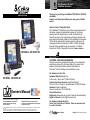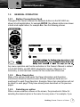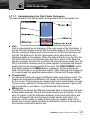
1
Our Thanks to You and
Customer Assistance
Thank you for purchasing a CobraMarineTM MC 600Ci or MC 600Cx
chartplotter.
Properly used, this product will give you many years of reliable
service.
www.cobra.com
How Your Cobra® Chartplotter Works
The CobraMarineTM chartplotter is a state-of-the-art computerized electronic
chart system, designed as a sophisticated navigation aid. User friendly
operations make the chartplotter easy to operate. All calculations and
information necessary for the navigation are performed and displayed on the
screen quickly and accurately providing all of the capabilities of a conventional
GPS but with the added benefit of a powerful electronic chart display. The
cartographic information is obtained from C-MAPTM C-CARDs (cartography
data cards) that are available through your local dealer. For additional
information on C-MAPTM Cartography visit web site at www.c-map.com.
MC 600Cx
and
MC 600Cx EU
CUSTOMER ASSISTANCE INFORMATION
Should you encounter any problems with this product, or not understand its
many features, please refer to this Owner’s Manual. If you require further
assistance after reading this Owner’s Manual, Cobra Electronics
CorporationTM offers the following customer assistance services:
For Assistance in the U.S.A
MC 600Ci
and
MC 600Ci EU
Owner’s Manual
All rights reserved. No part of this publication may be reproduced or distributed in any form or by any means, or stored in a database or retrieval
system, without prior written permission of the publisher.
©2006 Cobra Electronics CorporationTM
©2006 Cobra® Electronics Europe Limited
6500 West Cortland Street, Chicago
Illinois 60707 USA
Dungar House, Northumberland Avenue, Dun Laoghaire
County Dublin, Ireland
Automated Help Desk English only.
24 hours a day, 7 days a week 773-889-3087 (phone).
Customer Assistance Operators English and Spanish.
8:00 a.m. to 6:00 p.m. through Fri. (excepth holidays) 773-889-3087 (phone).
Questions English and Spanish.
Faxes can be received at 773-622-2269 (fax).
Technical Assistance
English only: www.cobra.com (on-line: Frequently Asked Questions).
English and Spanish: [email protected] (e-mail).
For Assistance Outside the U.S.A
Contact Your Local Dealer or Distributor. Please see www.cobra.com
for contact information.
Cobra®, NightWatch®, Nothing Comes Close to a Cobra® and the snake design are registered trademarks of Cobra Electronics Corporation, USA.
Cobra Electronics CorporationTM, CobraMarineTM and iASAPTM are trademarks of Cobra Electronics Corporation, USA.
C-MAPTM, C-MAP Navigation Technology, C-MAP NT MAX TM and C-MAP NT+ TM are registered trademarks of C-MAP S.r.l.
(S3igCO7vc/S3egCO7vc-a1000-251105)
A1
Owner's Manual
Nothing Comes Close to a Cobra®
Software Features and
Technical Specifications
Control and Indicators
SOFTWARE FEATURES
Detailed Base Map Included
3D Mapping (view charts in either top down or new 3D perspective modes)
12 Channel WAAS GPS with iASAPTM
Sunlight and NightWatchTM Modes
Easy surfing among the available pages (Data, Highway, Sun & Moon,
Split, GPS Status, System and Welcome pages)
Fish Finder and Combo pages (available with Fish Finder device connected)
DSC Calling integration
1000 Waypoints and 50 Routes (50 Waypoints/Route)
Create, Move, Insert, Edit or Erase Waypoint
Create, Save, Name, Edit or Follow a Route
Navigation to Goto
Route Data Report and User Points (Marks/Waypoints) List pages
Find Ports Services, Ports, Tide Stations, Wrecks, Obstructions,
Coordinates and User Points
Display Tide Info and Tide Graph page
Automatic Info on cartographic objects and User Points
Display vessel's position, direction and Track
10 Tracks with 16 Color Options
Alarms Handling (Anchor Drag, Arrival, Off Course, Proximity, Depth, Etc.)
Man OverBoard (MOB) to navigate back to a missing person or object
Demo Modes
TECHNICAL SECIFICATIONS
Power Consumption
Interface
Autopilot Interface
Display
Display Resolution
Cartography
Operating Range
Water Proof Specification
Memory
Keyboard
Weight
SOFTWARE BUTTONS FUNCTIONALITY
The software buttons have different functions according to the modes of
operation: their labels for the current functions, are shown on the screen right
above the buttons. They can also be used like FM radio preset buttons to
save quick access to your favorite pages.
When pressing the ESC button the four software button, labels disappear.
A2
Owner's Manual
Nothing Comes Close to a Cobra®
A3
: 10 - 35 V
: NMEA-0183
: NMEA-0180, NMEA-0180/CDX, NMEA-0183
: 6” Color TFT with Anti-Reflective Coating (Active Area 5.7”)
: 240 x 320 pixels
: C-MAP NT MAXTM or C-MAP NT+TM C-CARDs
: 0/+55 degree Celsius
: Submersible to IPX7 or JIS7
: Non volatile with battery back-up
: Silicon rubber, backlight
: 630 gr.
Owner's Manual
Nothing Comes Close to a Cobra®
Warnings and Cautions
WARNINGS AND CAUTIONS
Before using your CobraMarineTM MC 600C chartplotter please read these
general precautions and warnings.
Electronic charts displayed by the chartplotter are believed to be accurate and
reliable, but they are not intended to replace official charts which should remain your
main reference for all the matters related to the execution of a safe navigation. For
this reason we would like to remind you that you are required to carry on board and
use the officially published and approved nautical charts.
Please read through this manual before the first operation. If you have any
questions, please contact the customer service or your local chartplotter dealer or
distributor.
Extensive exposure to heat may result in damage to the chartplotter.
Connection to the power source with reversed polarity will damage the
chartplotter severely. This damage is not covered by the warranty.
Do not disassemble. The chartplotter contains dangerous high voltage circuits
which only experienced technicians MUST handle.
The C-MAPTM C-CARDs are available from your local dealer.
Exposure of the display to UV rays may shorten the life of the liquid crystals used
in your plotter. This limitation is due to the current technology of the LCD displays.
Avoid overheating which may cause loss of contrast and, in extreme cases, a
darkening of the screen. Problems which occur from overheating are reversible
when temperature decreases.
SCREEN CLEANING PRECAUTIONS
Cleaning your chartplotter screen is a very important operation and must be done
carefully, as the window's surface is covered with and antireflective coating. The
following is the cleaning procedure: you use a tissue or lens tissue and a cleaning
spray containing Isopropanol (a normal spray cleaner sold for PC screens, for
example PolaClear by Polaroid). Fold the tissue or lens tissue into a triangular
shape, moisten the tip and use the index finger behind a corner to move the tissue
across the surface, in overlapping side to side strokes. If the tissue is too wet, a
noticeable wet film will be left in its path and you will need to repeat the process. If
too dry, the tissue won’t glide easily, and may damage the surface.
Nothing Comes Close to a Cobra®
1
Included in This Package and
C-MAP C-CARD
WHAT IS IN THE BOX?
When the package containing the chartplotter is first opened, please check it
for the following contents (if any parts are missing contact the dealer the
chartplotter was purchased from):
CobraMarineTM MC 600C chartplotter
Power Data Cable
Tilt and Swivel Mounting Bracket
Two Removable Faceplates
Owner’s Manual
Quick Reference Guide
External GPS Antenna with 10 Meter Cable (ONLY on MC 600Cx model)
Flush Mount Kit (ONLY on MC 600Cx with model)
MC 600C Chart Details
The chartplotter has a built-in world map that can be used for Route planning.
To use the chartplotter as a navigation aid, charts are required with detailed
information for the area. This chart cartridge is called a C-CARD. C-CARDs
are available from your local C-MAPTM dealer. See Chapter 6 for the insert/
remove C-CARD procedure. The C-CARD can be inserted by removing the
faceplate.
2
Owner's Manual
Table of Contents
1.
MANUAL ORGANIZATION
1.1.
TABLE OF CONTENTS
INTRODUCTION
................................................................................................................................. A1
OUR THANK S TO YOU ................................................................................................................................. A1
CUSTOMER ASSISTANCE .............................................................................................................................. A1
CONTROL AND INDICATORS ......................................................................................................................... A2
SOFTWARE BUTTONS FUNCTIONALITY ...................................................................................................... A2
SOFTWARE FEATURES ................................................................................................................................. A3
TECHNICAL SPECIFICATIONS ....................................................................................................................... A3
WARNINGS AND CAUTIONS ............................................................................................................................. 1
SCREEN CLEANING PRECAUTIONS ................................................................................................................ 1
WHAT IS IN THE BOX? .................................................................................................................................... 2
MC 600C Chart Details
.................................................................................................................................... 2
1. MANUAL ORGANIZATION ............................................................................................................................. 3
1.1. TABLE OF CONTENTS ......................................................................................................................... 3
1.2. GENERAL OPERATION ....................................................................................................................... 7
1.2.1. Button Conventions Used .......................................................................................................... 7
1.2.2. Menu Description ....................................................................................................................... 7
1.2.3. Selecting an option ..................................................................................................................... 7
1.2.4. Alphanumeric Input Procedure ................................................................................................... 8
2. BASIC OPERATION .................................................................................................................................. 10
2.1. SWITCHING ON/OFF .......................................................................................................................... 10
2.1.1 Switching On ............................................................................................................................ 10
2.1.2 Switching Off ............................................................................................................................ 10
2.1.3. Auto power On Description ...................................................................................................... 10
2.2. INITIAL SETUP .................................................................................................................................. 10
2.2.1. Definitions of Selections ........................................................................................................... 11
2.3. ADJUSTING THE BACKLIGHTING AND CONTRAST ....................................................................... 12
2.4. PAGE SURFING .................................................................................................................................. 13
2.4.1. Pages selection ........................................................................................................................ 13
2.5. DEMO MODE .................................................................................................................................. 14
2.5.1. Full Demo ................................................................................................................................. 14
2.5.2. Demo a Route .......................................................................................................................... 14
2.5.3. Custom Demo .......................................................................................................................... 14
2.6. MOVING AND ZOOMING ON CHART ................................................................................................ 14
2.6.1. Pan
.................................................................................................................................. 14
2.6.2. Zoom
.................................................................................................................................. 15
2.6.3. Esc back to chart ...................................................................................................................... 15
2.7. CHANGING DATA FIELDS ON MOST PAGES .................................................................................. 15
2.7.1. Number of Data Fields ............................................................................................................. 15
2.7.2. Change Data Fields ................................................................................................................. 16
2.7.3. Available Data Options ............................................................................................................. 17
2.8. CREATING A USER POINT ................................................................................................................ 17
2.8.1. Creating a New Waypoint ........................................................................................................ 17
2.8.2. Creating a New Mark ............................................................................................................... 18
2.9. CREATING A BASIC ROUTE ............................................................................................................. 18
2.10. USING GOTO .................................................................................................................................. 19
2.11. USING FIND
.................................................................................................................................. 19
Nothing Comes Close to a Cobra®
3
Table of Contents
2.12. USING MOB
.................................................................................................................................. 20
2.12.1. Inserting MOB .......................................................................................................................... 20
2.12.2. Deleting MOB ........................................................................................................................... 20
3. PAGE INFORMATION AND OPERATION ................................................................................................... 21
3.1. PAGE SELECTION AND PRESETS - SETUP .................................................................................... 21
3.2. WELCOME PAGE ............................................................................................................................... 22
3.2.1. Operations ............................................................................................................................... 22
3.3. CHART ONLY PAGE ........................................................................................................................... 24
3.3.1. Description ............................................................................................................................... 24
3.3.2. Operations ............................................................................................................................... 24
3.3.2.1. Available Layouts of CHART Page ............................................................................ 24
3.3.2.2. Changing Data Options ............................................................................................. 24
3.3.2.3. Operations on User Points ......................................................................................... 25
3.3.2.4. Software Buttons ....................................................................................................... 25
3.3.3. Menu
.................................................................................................................................. 25
3.4. DATA PAGE
.................................................................................................................................. 27
3.4.1. Description ............................................................................................................................... 27
3.4.2. Operations ............................................................................................................................... 27
3.4.2.1. Available Layouts of DATA Page ............................................................................... 27
3.4.2.2. Changing Data Options ............................................................................................. 27
3.4.2.3. On Screen Instructions .............................................................................................. 28
3.4.3. Menu
.................................................................................................................................. 28
3.5. HIGHWAY PAGE ................................................................................................................................ 30
3.5.1. Description ............................................................................................................................... 30
3.5.2. Operations ............................................................................................................................... 30
3.5.2.1. Available Layouts of HIGHWAY Page ....................................................................... 31
3.5.2.2. ZOOM IN AND ZOOM OUT ...................................................................................... 31
3.5.3. Menu
.................................................................................................................................. 31
3.6. SUN AND MOON PAGE ........................................................................................................................ 32
3.6.1. Description - “Telling” Tide ....................................................................................................... 32
3.6.2. Operations ............................................................................................................................... 32
3.6.2.1. Available Layouts of SUN and MOON Page. ............................................................. 33
3.6.2.2. Finding the Nearest Tide Stations .............................................................................. 33
3.6.2.3. Finding a Tide Station on a map ................................................................................ 33
3.6.2.4. Changing the date for the Tide Chart ......................................................................... 34
3.6.2.5. Various Animation Options ........................................................................................ 34
3.7. FISH FINDER PAGE .......................................................................................................................... 35
3.7.1. Description ............................................................................................................................... 35
3.7.1.1. Understanding the Fish Finder Echogram ................................................................. 37
3.7.2. Operations ............................................................................................................................... 38
3.7.2.1. Available Layouts of FISH FINDER Page .................................................................. 38
3.7.2.2. Changing Data Options ............................................................................................. 38
3.7.2.3. Split Mode of the FISH FINDER Page ....................................................................... 38
3.7.3. Menu
.................................................................................................................................. 38
3.8. COMBO MODE PAGE ........................................................................................................................ 41
3.8.1. Description ............................................................................................................................... 41
3.8.2. Operations ............................................................................................................................... 41
3.8.2.1. Moving the location of the Chart Window ................................................................... 41
3.8.2.2. Available Layouts of COMBO MODE Page ............................................................... 42
3.8.2.3 Changing Data Options ............................................................................................. 42
3.8.2.4. Changing the Size of Windows .................................................................................. 42
3.8.3. Screen Control ......................................................................................................................... 43
4
Owner's Manual
Table of Contents
3.9.
SPLIT MODE PAGE ............................................................................................................................ 44
3.9.1. Description ............................................................................................................................... 44
3.9.1.1. Available Layouts of SLIT MODE Page ..................................................................... 44
3.9.1.2. Changing Data Options ............................................................................................. 44
3.9.1.3. Changing the size of windows ................................................................................... 45
3.9.1.4. Changing the Screen Control .................................................................................... 45
3.9.2. Menu
.................................................................................................................................. 45
3.9.2.1. CHART Page ............................................................................................................. 45
3.9.2.2. HIGHWAY Page ........................................................................................................ 45
3.9.2.3. FISH FINDER Page ................................................................................................... 45
3.10. GPS PAGE
.................................................................................................................................. 46
3.10.1. Description ............................................................................................................................... 46
3.10.1.1. Changing Data Options ............................................................................................. 46
3.10.2. Menu
.................................................................................................................................. 47
3.11. SYSTEM PAGE .................................................................................................................................. 48
3.11.1. Description ............................................................................................................................... 48
3.11.2. Each Setting Description .......................................................................................................... 48
4. ADVANCED OPERATION ............................................................................................................................ 49
4.1. MEASURE FUNCTION ....................................................................................................................... 49
4.2. ADVANCED WAYPOINT OPERATIONS ............................................................................................ 49
4.2.1. Deleting a Waypoint ................................................................................................................. 49
4.2.2. Moving a Waypoint ................................................................................................................... 50
4.2.3. Inserting a Waypoint ................................................................................................................ 50
4.2.4. Editing a Waypoint ................................................................................................................... 50
4.3. ROUTE OPERATIONS ........................................................................................................................ 50
4.3.1. Selecting existing and Naming new Routes ............................................................................. 51
4.3.2. Basic Route List Operations ..................................................................................................... 51
4.4. USING TRACK .................................................................................................................................. 52
4.5. USER POINTS LIST ............................................................................................................................ 53
4.5.1. Selecting Existing and naming new User Points ...................................................................... 53
4.5.2. Basic User Point List Operations .............................................................................................. 53
4.6. USER C-CARD OPERATIONS ........................................................................................................... 54
4.6.1. User C-CARD Page ................................................................................................................. 54
4.6.2. Formatting User C-CARD ........................................................................................................ 54
4.6.3. Saving file on User C-CARD .................................................................................................... 55
4.6.4. Loading file from User C-CARD ............................................................................................... 55
4.6.5. Deleting file from User C-CARD ............................................................................................... 55
4.7. INFO
.................................................................................................................................. 56
4.7.1. Setting Automatic Info .............................................................................................................. 56
4.7.2. Selecting Automatic Info .......................................................................................................... 56
4.7.3. Info on objects with Pictures ..................................................................................................... 56
4.7.4. Info Tree and Expanded Info page ........................................................................................... 57
4.8. CURRENT PREDICTIONS .................................................................................................................. 57
4.9. DYNAMIC NAV AIDS .......................................................................................................................... 57
4.10. PICTURES
.................................................................................................................................. 58
4.11. DSC CALLING .................................................................................................................................. 58
4.11.1. Advanced DSC for VHF Radio with NMEA 0183 Output .......................................................... 59
4.11.2. Contact List .............................................................................................................................. 59
5. SYSTEM PAGE SETTINGS .......................................................................................................................... 60
5.1. SCREEN SHOT AND DESCRIPTIONS .............................................................................................. 60
5.2. OPERATIONS BY SETTING GROUP ................................................................................................. 60
Nothing Comes Close to a Cobra®
5
Table of Contents
5.2.1. Display Settings ....................................................................................................................... 60
5.2.2. Chart Settings .......................................................................................................................... 61
5.2.2.1. Chart Presentation ..................................................................................................... 61
5.2.2.2. Depth Presentation .................................................................................................... 63
5.2.2.3. Land Presentation ..................................................................................................... 64
5.2.2.4. Advanced Chart Settings ........................................................................................... 64
5.2.3. General .................................................................................................................................. 67
5.2.4. Fish Finder Settings ................................................................................................................. 67
5.2.4.1. Display Settings ......................................................................................................... 68
5.2.4.2. Sensitivity Settings .................................................................................................... 68
5.2.4.3. Transducer Settings .................................................................................................. 69
5.2.5. Alarm Settings .......................................................................................................................... 70
5.2.5.1. General Alarms .......................................................................................................... 70
5.2.5.2. GPS Alarms ............................................................................................................... 70
5.2.5.3. Fish Alarms ............................................................................................................... 71
5.2.6. Units
.................................................................................................................................. 71
5.2.7. Pages On/Off ........................................................................................................................... 72
5.2.8. GPS Settings ........................................................................................................................... 72
5.2.9. Demo
.................................................................................................................................. 73
5.2.9.1. Custom Demo ............................................................................................................ 73
5.2.10. Com Settings ........................................................................................................................... 74
5.2.11. About
.................................................................................................................................. 75
6. INSTALLATION
.................................................................................................................................. 76
6.1. BASIC
.................................................................................................................................. 76
6.1.1. Chartplotter Dimensions ........................................................................................................... 76
6.1.2. C-CARD Inserting and Removing ............................................................................................ 76
6.1.3. Chartplotter Installation and Removing .................................................................................... 77
6.1.4. Wiring and Connectors ............................................................................................................. 77
6.2. ADVANCED
.................................................................................................................................. 78
6.2.1. External NMEA Connection ..................................................................................................... 78
6.2.2. GPS Connection (on MC 600Cx with External GPS) ............................................................... 78
6.2.3. Autopilot and Basic DSC VHF Connection ............................................................................... 78
6.2.4. External Alarm Connection ...................................................................................................... 79
6.2.5. Fish Finder ............................................................................................................................... 79
6.3. MOUNTING THE GPS ANTENNA (ONLY on MC 600Cx model) ........................................................ 79
6.3.1. Antenna Flush Mounting .......................................................................................................... 80
7. MAINTENANCE
.................................................................................................................................. 81
7.1 SYSTEM TEST .................................................................................................................................. 81
8. OPTIONAL ACCESSORIES ......................................................................................................................... 82
8.1. PC-PLANNER .................................................................................................................................. 82
8.2. MF 2500 FISH FINDER ....................................................................................................................... 82
8.2.1. Transducers ............................................................................................................................. 82
9. APPENDIX
.................................................................................................................................. 83
9.1. TERMS
.................................................................................................................................. 83
9.2. GPS
.................................................................................................................................. 90
9.2.1. How GPS Works ...................................................................................................................... 90
9.2.2. Position Fixing Accuracy: HDOP .............................................................................................. 91
9.3. WORLD CITY TIME ZONES ............................................................................................................... 93
INDEX
6
.................................................................................................................................. 94
Owner's Manual
General Operation
1.2.
GENERAL OPERATION
1.2.1. Button Conventions Used
Throughout this Owner’s Manual, the hardware buttons on the MC 600C are
shown in bold capital letters, for example ENTER; the software buttons are shown
in bold small capital letters, for example EDIT. See the following pictures.
Any menu operation and function activation in this Owner’s Manual is related
to both MC 600Cx and MC 600Ci chartplotter models. Whenever it is
necessary, a note has been inserted for the model with differences.
1.2.2. Menu Description
Many of the options listed under the Page Information and Operation
Instructions should be read from start to finish. Duplicate items are not
mentioned for each Page Operation. Example, Menu Item descriptions will not
be listed for each page if they have already been described on the previous
pages.
1.2.3. Selecting an option
When a menu window is shown on the screen, the procedure to follow for
selecting the desired option is the same for every menu. For example, if you
Nothing Comes Close to a Cobra®
7
General Operation
have activated the menu from the CHART Page (by pressing the MENU
button) to select the option you want, “NUMBER OF DATA FIELDS” option,
follow the procedure listed below:
1. Use the UP and DOWN CURSOR buttons to select the desired option,
“NUMBER OF DATA FIELDS”.
2. Press the ENTER button: a drop down box appears with the available
selections “2”, “4”, “6”, “HIDE”.
3. Use the UP and DOWN CURSOR buttons to select a desired choice.
4. Press the ENTER button to confirm, or the ESC button to abort and return
to the previous settings.
Pressing the RIGHT CURSOR button will sometimes perform like the ENTER button
during this operation.
1.2.4. Alphanumeric Input Procedure
Information is keyed into the chartplotter for example when editing a Waypoint
(see the following picture), or when entering Setup information.
8
Owner's Manual
General Operation
When the field is highlighted:
1. Use the RIGHT or LEFT software buttons at the bottom to highlight the field
you would like to change.
2. Use the UP, DOWN, RIGHT or LEFT CURSOR buttons to step through
the available characters until the desired character is highlighted.
3. Press the ENTER button to confirm; the selected character appears in the
highlighted field on the top line.
4. Repeat this procedure until you complete your entry.
5. Press the SAVE software button when the entry is complete.
This keypad is designed to reduce the number of button presses needed naming
points and entering data. It can be disabled and the more conventional method
used. If desired, it is disabled from the General settings of the SYSTEM Page.
Nothing Comes Close to a Cobra®
9
Switching On/Off
2.
BASIC OPERATION
Refer to the foldout on the front cover to identify the various controls and indicators
on your chartplotter.
2.1. SWITCHING ON/OFF
Before powering On the chartplotter, check for the correct voltage (10-35 volt dc).
2.1.1
Switching On
Press and hold the PWR button for one (1) second. The chartplotter shows
you the Logo Screen, Caution Notice (press the ENTER button) and then the
WELCOME Page in sequence. See the INITIAL SETUP Page instruction for
first time switch On instructions.
2.1.2
Switching Off
Press and hold the PWR button for three (3) seconds. A countdown timer
appears on the screen, if you release the button before the countdown timer
reaches zero, the chartplotter will remain On.
2.1.3. Auto power On Description
If you power Off the chartplotter during the normal working using an accessory
switch (not pushing the PWR button), then the chartplotter will power On
automatically when that same switch is turned back On.
2.2. INITIAL SETUP
Initial power on settings page that asks the user to input crucial setup
information. The FIRST TIME - GPS SETUP Page appears at power On after
the Logo Screen.
10
Owner's Manual
Initial Setup
2.2.1. Definitions of Selections
This menu allows you to select some of the basic setup information the first
time the chartplotter is powered On. This information can be changed at any
time either from the SYSTEM Page (see Chapter 5) or by resetting the
chartplotter. Select the correct setup option and select “DONE” and press the
ENTER button when complete. Please refer to section 1.2 for more
information on how to enter information.
“LANGUAGES” - Selects the language in which you wish information to
be displayed (for screen labels, menus and options, but it does not affect
the map information).
“BOAT MANUFACTURER” (optional) - Enters the boat manufacturers
name to be displayed on the initial Logo Screen.
“BOAT MODEL” (optional) - Enters the Model Name/Number of your
boat to be displayed on the Logo Screen.
“BOAT NAME” (optional) - Enters the boat name to be displayed on the
Logo Screen.
“COMPASS BEARINGS” - Selects either degrees magnetic or degrees
true. If magnetic readings are selected the variation is computed
automatically for every zone as soon as the chart is displayed.
“DISTANCE UNITS” - Sets the distance unit among the available choices.
The default setting is Nm (Nautical Miles). Other options are Statute Miles
(Sm) and Kilometers (Km).
“SPEED UNITS” - Sets the speed unit among the available units. The
default setting is Knots (Nautical Miles/Hour). Other options are Miles per
Hour (Mph) and Kilometers per Hour (Kph).
“DEPTH UNITS” - Sets the depth units among the available units. The
default setting is Ft (Feet). Other options are Meters (Mt) and Fathoms (Ft).
“GPS ALTITUDE UNITS” - Sets the altitude of GPS Antenna on the
Nothing Comes Close to a Cobra®
11
Initial Setup
medium sea level unit among the available units. The default setting is Ft
(Feet). Other options are Meters (Mt) and Flight Level (FL).
“TIME REFERENCE” - Allows switching the Time Reference between
UTC or Local. After entering the Local Time offset, your local time will be
displayed. See Par. 5.2.6 for more detailed information.
“TIME FORMAT” - Sets you preferred time format. The default setting is
24 hour time.
“DATE FORMAT” - Sets you preferred date format between MM-DD-YY
(month-day-year) and DD-MM-YY (day-month-year). The default setting is
MM-DD-YY.
“WIND SPEED UNITS” - Sets the Wind Speed units among the available
units. The default setting is Knots (Nautical Miles/Hour). Other options are
M/S, BFT, Miles per Hour (Mph) and Kilometers per Hour (Kph).
“APPROXIMATE MAX SPEED” - This information will be used to set up
the analog style speedometer gauge.
“CURRENT ENGINE HOURS” (optional) - Starting value that will be
used for the engine hours gauge.
“WAYPOINT ARRIVAL ALARM” - Sets the distance you would like to
have alarm sound when approaching a Waypoint.
“XTE ALARM” - Sets the distance you go off course before an off course
alarm will sound.
“RESET DEFAULTS” - Changes all the settings on this page back to the
original settings.
2.3. ADJUSTING THE BACKLIGHTING AND CONTRAST
You can change the level of backlight and contrast for the screen.
1. Press the PWR button. On the screen appears:
2. Use the software buttons to adjust the backlight and contrast levels.
12
Owner's Manual
Backlight and Contrast
Page Surfing
3. Wait or press the ENTER button to return to the chart screen with the new
light levels retained.
Continuously pressing the PWR button from this screen will toggle you through the
available color palettes.
2.4. PAGE SURFING
There are many different pages of data and information available. You can
select the page you wish “by surfing” among the available pages.
2.4.1. Pages selection
Pressing the PAGE button causes TABs to appear with the pages that you
can scroll through. Continually pressing the PAGE button or the RIGHT and
LEFT CURSOR buttons allow you to scroll forwards or backwards through the
available pages. The TABs disappear after several seconds allowing you to
resume full operation of the selected page.
Please note that these available pages can be customized from the settings page
(see Par. 3.1).
The option of having the page TABs appear at the top of the page can be turned Off
from the SYSTEM Page in the General settings menu.
Nothing Comes Close to a Cobra®
13
Demo Mode
2.5. DEMO MODE
DEMO MODE is great for practicing the actual use of a product when the
satellites signals and internal alarms are not available. When the device is in
DEMO MODE, the GPS receiver is turned Off, so it is impossible to navigate.
Do not try to navigate in a DEMO MODE. While the DEMO MODE is turned On, the
GPS receiver is not active. All satellite signal strength bars are only a simulation and
do not indicate any actual satellite signals.
DEMO MODE can be selected from the WELCOME Page (see Par. 3.2) or
from the SYSTEM Page (see Par. 5.2.9) .
Selecting the DEMO MODE would bring up the choice of three options for
demo. The DEMO MODEs are:
2.5.1. Full Demo
This mode is designed for in store or on display demonstration. This unit will
automatically scroll through various displays and demonstrate the product.
2.5.2. Demo a Route
This mode allows the user to select a Route that they have already planned.
2.5.3. Custom Demo
This mode allows you to enter a desired course and speed for the
demonstration. The simulated GPS position will start directly from the Pointers
position on the chart.
2.6. MOVING AND ZOOMING ON CHART
Use the CURSOR buttons to move around or Pan the chart. Also use the
ZOOM IN and ZOOM OUT buttons to change the chart scale so that a smaller
or larger area is shown on the chart.
2.6.1. Pan
Controlled by the CURSOR buttons, the Pointer is an important tool that can
be used to pan to other map locations, mark and edit Waypoints and Routes
and review information about on-screen map items and Waypoints. Use the
14
Owner's Manual
Moving and Zooming on Chart
map Pointer to pan away from your present position and scroll to other map
areas even outside of your current detail coverage. While panning past the
edge of the current map display, the screen actively scrolls forward to provide
continuous map coverage.
2.6.2. Zoom
Zoom function is generally used to change a map scale and show relevant
detail content.
ZOOM OUT - Press the ZOOM OUT button to change the scale and show
less details of a larger area.
ZOOM IN – Press the ZOOM IN button to show more details of a smaller
area.
2.6.3. Esc back to chart
The function of the ESC button is to come back to the CHART Page from
every other page. The ESC button will also move back from a selection menu
or to clear the screen.
Please note that the ESC button is used to come back to original map Pointer
location and a map scale after zooming and panning.
2.7. CHANGING DATA FIELDS ON MOST PAGES
It is possible to change the number of data fields shown at the bottom of most
Pages. The number of fields and the value displayed in the field can be
changed by selecting the MAIN Menu and then either the “NUMBER OF
DATA FIELDS” or “CHANGE DATA FIELDS” option.
2.7.1. Number of Data Fields
Most pages give the ability to adjust the number of fields displayed on a given
page. The available choices are predefined in the MAIN Menu. To change the
number of data fields follow the procedure below:
1. Press the MENU button. The MAIN Menu will be activated.
2. Use the UP and DOWN CURSOR buttons to select the “NUMBER OF
DATA FIELDS” option.
3. Press the ENTER button to access the available selections.
4. Use the UP and DOWN CURSOR buttons to select a desired choice.
5. Press the ENTER button to confirm, or the ESC button to abort and return
to the previous settings.
Nothing Comes Close to a Cobra®
15
Changing Data Fields
2.7.2. Change Data Fields
Each data field present on a given page (no matter the number of data fields)
can be customized to obtain the best navigational information.
1. Press the MENU button. The MAIN Menu will be activated.
2. Use the UP and DOWN CURSOR buttons to select the “CHANGE DATA
FIELDS” option.
3. Press the ENTER button to confirm. A yellow frame appears around one of
the data fields.
4. Use the UP, DOWN, RIGHT and LEFT CURSOR buttons to highlight and
choose an individual data field.
5. Press the ENTER button to display the available data options for the
chosen data field.
6. Use the UP and DOWN CURSOR buttons move through the options.
7. Press the ENTER button to select the on screen option or the ESC button
to cancel and return to the previously selected data.
You can also complete this by holding the MENU button. This will place a yellow
frame around one of the fields as per step 3 above.
16
Owner's Manual
Available Data Options
Creating a User Point
2.7.3. Available Data Options
All the available choices for the Data Fields are presented in the table below.
Keep in mind that some of them are characteristic only to one specified page.
The yellow bar on the right will scroll down as you move down the list.
2.8. CREATING A USER POINT
A User Point is an object that you can place on the charts to mark a specific
point. The chartplotter features two types of User Points: Marks and
Waypoints.
2.8.1. Creating a New Waypoint
A Waypoint is created when entering a Route:
1. Move the Pointer to the desired location on the chart.
2. Press the ENTER button.
3. Use the UP or DOWN CURSOR button to select “NEW WAYPOINT” and
press the ENTER button. The new Waypoint is placed.
Nothing Comes Close to a Cobra®
17
Creating a Basic Route
4. Move the Pointer off the location to accept.
2.8.2. Creating a New Mark
A Mark can be created at anytime. Marks are used for marking points outside
of a Route.
1. Move the Pointer to the desired location on the chart.
2. Press the ENTER button.
3. Use the UP or DOWN CURSOR button to select “NEW MARK” and press
the ENTER button. The new Mark appears on your Pointer.
4. Move the Pointer off the location to accept.
You can also use the shortcut software buttons that appear when moving the
Pointer. See the following picture:
2.9. CREATING A BASIC ROUTE
To create a Route:
1. Move the Pointer to the desired location on the chart.
2. Press the ENTER button.
3. Use the UP or DOWN CURSOR button to select “NEW WAYPOINT” and
press the ENTER button. This places the first Waypoint of the new Route
on your Pointer position. To place the next Waypoints of the Route repeat
the above procedure.
4. Move the Pointer off the location to accept or press the ENTER button to
edit.
18
Owner's Manual
Using Goto and Find
2.10. USING GOTO
The GOTO function allows instant plotting of course to selected target. After
pressing the GOTO button on most of the pages, the sub-menu on a Pointer
position appears and it is possible to choose beneath mentioned options:
“GOTO POINTER” - Sets the Pointer location as the destination.
“GOTO POINT” - Shows the “User Point” list, that gives information on all
stored User Points.
“FOLLOW ROUTE” - Brings up the “Select Route” list with the most
recently used highlighted.
“NEW ROUTE” - Brings up the “Selected Route” list but with the next
open Route highlighted. Software button choices are: EDIT, ACCEPT.
“NEW WAYPOINT” - A new Waypoint is created and set as the
destination Waypoint.
“NEW MARK” - A new Mark is created.
“MOB” - Man OverBoard (MOB) function. See Par. 2.12 for details.
“FIND” - Find function. See Par. 2.11 for details.
2.11. USING FIND
The Find function allows searching for the nearest Ports, Port Services, Tide
Stations, Wrecks, Obstructions loaded on the C-CARD or it centers the screen
over a selected User Point or at desired Coordinates. When you press the
FIND button (or choose Find from a menu option) a list of available objects to
search is shown.
A Warning message is shown when activating the Find function if no C-CARD
inserted.
Nothing Comes Close to a Cobra®
19
Using MOB
2.12. USING MOB
If a person or object is lost overboard and you need to return to the location,
use the MOB (Man OverBoard) function. This function enables you to
simultaneously mark and set a course to a location for quick response to
emergency situations.
To activate the MOB function, a valid GPS fix must be available.
2.12.1. Inserting MOB
To activate a MOB function follow the procedure below:
1. Press the MOB button. A dialog box with a message “MOB is activated”
will appear on a screen and a MOB Waypoint will be created.
2. If the NMEA output is turned On, the warning dialog box is given: “Turn off
autopilot before setting MOB point as destination”
2.12.2. Deleting MOB
To cancel the MOB function
1. Use the CURSOR button to move the Pointer over the MOB icon.
2. Choose the DELETE or STOP NAV software buttons at the bottom of the
display.
20
Owner's Manual
Page Selection and Presets
3.
PAGE INFORMATION AND OPERATION
3.1. PAGE SELECTION AND PRESETS - SETUP
Any page can be turned ON or OFF using the following procedure:
1. Press the PAGE button several times to select “SYSTEM” and then press
the ENTER button.
2. Use the UP and DOWN CURSOR buttons to select the “PAGES ON/
OFF” option and then press the ENTER button.
3. Press the ENTER button to change the page status (On or Off).
4. Press one of the bottom software buttons to assign it as a short cut to the
desired page. The RIGHT and LEFT CURSOR buttons can also be used
to change the selection if the page has already been assigned a button.
During future operations the ON pages can be selected using the PAGE
button which is generally used to scroll through all available pages.
Pages containing certain data like the Fish Finder and Combo are not accessible
unless that optional module is connected.
Press and hold one of the software buttons from any of the main pages to save that
as one of quick access pages.
Nothing Comes Close to a Cobra®
21
Welcome Page
3.2. WELCOME PAGE
The WELCOME Page is activated by default on Power On and appears after
the GPS position lock. Use the WELCOME Page to go to the most commonlyused features on the chartplotter that are otherwise more difficult to access.
All of the options in these large selection boxes are also available from other
pages and selections.
3.2.1. Operations
The CURSOR buttons are used to choose an individual feature box. Press the
ENTER button to display the available feature’s options. After selection use
the PAGE button to return to the WELCOME Page. 8 different options are
available from this page:
“MY BOAT ON CHART”: Goes back to the CHART Page, centered on
the vessel’s position.
“CLOSEST FUEL”: Goes right to the list of closest Fuel Stations with
distance and bearing listed.
“PICK A POINT”: Goes to the predefined User Point list with the closest
point highlighted.
“GAUGES AND DATA”: Goes to the DATA Page.
“FIND MARINE SERVICES”: Shows an icon selection table. Use the
CURSOR button to highlight an icon. A description of the type of service is
listed. Press the ENTER button to search for this type of service.
“SYSTEM SETTINGS”: Goes directly to the SYSTEM Page for setup info.
The System Page can also be accessed by pressing the MENU button twice
from most pages.
22
Owner's Manual
Welcome Page
“DEMO MODE”: Links to a secondary set of selection boxes. The DEMO
Mode is specified in further detail in Par. 2.5.
“DAY OR NIGHTWATCHTM MODE”: Selection toggles between Day and
NightwatchTM depending on what mode the display is in at the time of
selection.
The screen will be difficult to read if the chartplotter is in NightwatchTM mode and the
sun is to bright. With the chartplotter on, continuously pressing the PWR button will
get the chartplotter out of NightwatchTM mode.
Nothing Comes Close to a Cobra®
23
Chart Only Page
3.3. CHART ONLY PAGE
The CHART Page is the main page of the chartplotter. From this page the
user can select the desired map, get information about cartographic objects
on the maps, see the vessel position, its direction and speed, place points
(Marks, Waypoints), set a destination point and display additional features.
The chartplotter is provided with worldwide background cartography while the
detailed charts of the desired area are available on data cartridges.
3.3.1. Description
The picture below shows the CHART Page layout with displayed data fields
and a steering compass added at the top. It is possible to customize all fields
shown in the page as described later in this paragraph. The central section of
the screen provides visual guidance of a chart and the bottom of the page is
designed for navigation data display.
3.3.2. Operations
The CHART Page is used for display of electronic cartography, creating and
using the User Points, plotting position and navigational data.
3.3.2.1. Available Layouts of CHART Page
The data fields of the CHART Page can be customized as HIDE, 2, 4 or 6
through the MENU button. By default the CHART Page is specified for 2 data
fields and a Steering Compass added over a Horizon. The Compass can be
turned Off in the Main Menu of the CHART Page by pressing the MENU button.
3.3.2.2. Changing Data Options
The content of each data field can be adjusted to the user’s requirements. To
customize data options follow the procedure described in Par. 2.7.2 Changing
Data Fields.
24
Owner's Manual
Chart Only Page
3.3.2.3. Operations on User Points
Using the ENTER button we are able to create, edit and delete various User
Points used during further navigation. Those advanced operations are
explained in detail in Chapter 4.
3.3.2.4. Software Buttons
The functional software buttons are activated when moving the Pointer with
the CURSOR buttons. They acts as a shortcuts for the GOTO functions
including: GO TO POINTER, NEW ROUTE, NEW WAYPOINT, and NEW MARK. These
functions time out after several seconds. The ESC button disables these
software buttons for several more seconds.
3.3.3. Menu
The MAIN Menu (selected through the MENU button) of the CHART Page
provides the operations for the chart display.
Some of the more commonly accessed features are listed first.
Nothing Comes Close to a Cobra®
25
Chart Only Page
MAIN
“STOP NAVIGATION”: Stops navigation to destination, if Target is set.
“3D VIEW”: Changes from standard to 3D mode. This could also be used
to choose viewing angle.
“DYNAMIC NAV AIDS”: Turns ON or OFF the blinking lights on Nav-Aids.
“NIGHT MODE”: Toggles the color setting in color pallets directly between
the current daytime color pallet and night mode.
“MAP ORIENTATION”: Selects the orientation of your chart according to:
North Up (the map is shown with North upwards), Heading Up (the map is
shown with the ship's current heading upwards), Course Up (the map is
displayed with the currently selected course leg upwards).
“FONTS AND SYMBOLS”: On MAX charts it is possible to set the size of
all names and symbols drawn on the charts, selecting between Normal
size (the regular characters size) and Large size.
“CURRENT PREDICTIONS”: Shows the variation of the Tidal arrows on
the selected area at any given time. See also Par. 4.8
“MEASURE”: Allows measuring Distance and Bearing between two points
on the CHART Page. See also Par. 4.1.
“FIND”: The same as pushing the Find button. See Par. 2.11.
“TRACKS”: Allows the management of the Track. See also Par. 4.4.
“ROUTES”: Allows the management of the Route. See also Par. 4.3.
“USER POINTS LIST”: Selects the User Points List Page with information
on all stored User Points. See also Par. 4.6.
“USER C-CARD”: Allows the management of the User C-CARD . See
also Par. 4.6.
“ADVANCED CHART SETUP”: Goes directly to the System Menu and
into the Chart Settings.
DATA FIELDS
“CHANGE DATA FIELD”: Any data field can be highlighted and changed
to any available data option.
“STEERING COMPASS”: Enables or disables the display of the Steering
Compass in the top of the CHART Page.
“NUMBER OF DATA FIELDS”: Sets the number of fields displayed on
the CHART Page.
“ADVANCED DATA SETUP”: Goes directly to the System Menu and into
the Units menu.
The ESC button always bring you to the center of the chart.
26
Owner's Manual
Data Page
3.4. DATA PAGE
Use the DATA Page to customize the data options described below.
3.4.1. Description
The pictures below present the available DATA Page layouts with respect to
displayed data fields.
3.4.2. Operations
The main feature of the DATA Page is the ability to customize all data options
according to a user’s requirements.
3.4.2.1. Available Layouts of DATA Page
The choice for the number of fields is 1,3,6 or 10, and field values can be
configured by pressing the RIGHT or LEFT CURSOR button located on the
right side panel. The default page is the “3 Boxes” page with the AnalogueStyle Speedometer Gauge.
3.4.2.2. Changing Data Options
The content of each data field can be adjusted to user’s requirements. To
customize data options follow the procedure described in Par. 2.7.2 Changing
Data Fields. The default “Speed Gauge” data field can be also changed into
an “Analogue–Style Compass”.
Please note that some of the data options can be grayed out if unavailable. This can
be caused by NMEA data unavailable to support the data field or Items related to
Fish Finder when not connected.
Nothing Comes Close to a Cobra®
27
Data Page
3.4.2.3. On Screen Instructions
When first arriving at the page or after pressing the ENTER button, Screen
Instructions will appear at the top of the page. The Screen Instructions are On
by default and disappear after a few seconds.
This option can be turned OFF for more advanced users.
3.4.3. Menu
Pressing the MENU button while displaying the DATA Page shows not
only some standard menu options available from other pages like Stop
Navigation, Find and Night Mode, but it also shows some options unique to
the DATA Page such as Reset Trip Log, Reset Total Log, Reset Maximum
Speed, Screen Instructions and Data Field tools. Press the ENTER button
to accept any selected menu option or the ESC button to cancel your
choice.
“RESET TRIP LOG”: Resets the distance traveled since it was last reset.
“RESET TOTAL LOG”: Clears the total traveled distance.
“RESET MAX SPEED”: Resets the highest boat speed measured since
the Speed Log was switched On.
“SPEEDOMETER MODE”: Customizes the Analog speedometer gauge
for maximum performance based on the selected value. The best
resolution is given for the target speed of the chosen activity. The top
speed is determined from the initial setup page and can be changed in the
future from the About section in the SYSTEM Page.
28
Owner's Manual
Data Page
“SCREEN INSTRUCTIONS” at the top of the page are ON by default.
This option allows the users to turn OFF these Screen Instructions once
they are familiar with the features.
“DEFAULT DISPLAY”: Changes the DATA Page that is the first
displayed. Default page layout is set to 3 fields with the Analogue GPS
Speed shown.
Nothing Comes Close to a Cobra®
29
Highway Page
3.5. HIGHWAY PAGE
Whenever it is activated the HIGHWAY Page uses the most relevant
navigation information to provide digital and graphical steering guidance to the
destination.
3.5.1. Description
The picture below shows the layout of the HIGHWAY Page with 4 data fields
and a steering compass above the Horizon. The data fields and steering
compass are shown by default. It is possible to customize all fields shown in
the HIGHWAY Page, as described later in this section. The central section of
the screen provides visual guidance to the Waypoint on a graphical “highway
display”, and the bottom of the page is designed for navigation data display.
The line down the center of the highway represents the desired track line.
The distance between a vessel and a Target can be changed using the ZOOM IN
and ZOOM OUT buttons. The distance from the center line to the side of the
highway is indicated on the display.
As a vessel heads towards its destination, the highway perspective moves to
indicate progress to the Waypoint and the proper direction which should be
kept to stay on course. If a navigation Route is defined, the HIGHWAY Page
shows each Waypoint of the Route in sequence. “Clouds” are shown during
the day and “Stars” for when night mode is set.
3.5.2. Operations
The HIGHWAY Page provides access to functions and features using the
MENU button and software button options.
30
Owner's Manual
Highway Page
3.5.2.1. Available Layouts of HIGHWAY Page
The data fields of the HIGHWAY Page can be customized to HIDE, 2 or 4
through the MENU button. By default the HIGHWAY Page is specified for 4 data
fields and a Steering Compass added over the Horizon. It is possible to customize
all data fields according to the user’s requirements. To customize data options
follow the procedure described in Par. 2.7.2 Changing Data Fields.
3.5.2.2. ZOOM IN AND ZOOM OUT
The highway perspective range can be zoomed in or out to display a larger or
smaller view of a highway.
ZOOM OUT - Press ZOOM OUT button to change the scale and show a
wider, less detailed view. The distance from the center line to either side of
the highway will change from 0.2 -> 0.5 -> 1.0 -> 2.0 -> 4.0 -> 10.0.
ZOOM IN – Press the ZOOM IN to show a narrower, more detailed view.
3.5.3. Menu
The MAIN Menu of the HIGHWAY Page provides the same operations as the
CHART Page display but it also provides some of access to various options
and features related to the HIGHWAY Page.
“BACKGROUND IMAGE”: Allows the user to turn OFF the image
(‘Clouds’ or ‘Stars’) and show a blue background instead.
“STEERING COMPASS”: Turns ON or OFF display of the compass
above the Horizon.
“NUMBER OF DATA FIELDS”: Changes the HIGHWAY Page layout; it
can be set to 2, 4 or HIDE data fields.
Nothing Comes Close to a Cobra®
31
Sun and Moon Page
3.6. SUN AND MOON PAGE
The SUN and MOON Page presents a graphical chart that displays Tide
station information in a 24-hour span starting at midnight. The choice of
different dates and various Tide Stations all around the world is available.
Tide data shown on this page comes from an optional C-CARD data.
3.6.1. Description - “Telling” Tide
The picture below presents a layout of the SUN and MOON Page with 8 data
fields set by default and a graph showing Tide information from a given Tide
station. The highest Tides are represented by the top of the curve and the
lowest Tides by the bottom of the curve.
Tide heights are indicated at height of Tide above the mean low Tide.
“LATITUDE/LONGITUDE”: Location of the Tide symbol/station on the
chart.
“DATE/TIME”: Date and Time of the indicated data.
“HIGH WATER/LOW WATER”: The highest and lowest Tide heights of
the day.
“SUNRISE/SUNSET”: Time of day for sunrise and sunset.
3.6.2. Operations
The SUN and MOON Page provides Tide Info with relevance to desired Tide
Station and Location.
32
Owner's Manual
Sun and Moon Page
3.6.2.1. Available Layouts of SUN and MOON Page.
There is no possibility to change either the number of data fields nor their
content. The default number of fields is 8 including: Latitude, Longitude, High
Water Level, Low Water Level, Sunrise, Sunset, Date and Time.
3.6.2.2. Finding the Nearest Tide Stations
Tides are measured and predicted relative to local Tide Station. To select the
Nearest Tide Station from a current location follow the procedure below:
1. Press the MENU button to open the MAIN Menu of the SUN and MOON
Page.
2. Use the CURSOR buttons to select “FIND CLOSEST STATIONS” option
and press the ENTER button
3. The list of the Nearest Tide Stations, their names, distance from current
position and bearing will appear. Highlight your selection with the
CURSOR buttons, and press the ENTER button.
The result of your selection will be visible on a graph. If there is no available
Tide Station in the nearest area, the message appears. If necessary, use the
Pointer to select a location closer to a Tide Station and use the FIND feature
to find the closest station.
3.6.2.3. Finding a Tide Station on a map
Using the MENU button you can activate the Find option (also you can use
the FIND button).
1. Press the MENU button to open the MAIN Menu of the SUN and MOON Page.
2. Use the CURSOR buttons to select “FIND” option and press the ENTER
button (or just press the FIND button)
3. The list of individual options appears. Highlight the Tide Station option
with the CURSOR buttons, and press the ENTER button.
4. A list of Tide Stations will appear. Use the CURSOR buttons and the
ENTER button to choose a desired item and locate it on a chart.
Nothing Comes Close to a Cobra®
33
Sun and Moon Page
The result of your selection will be visible on a chart. An error message will
appear if there are no Tide Stations in the immediate area.
Use the Pointer to select a location closer to a Tide Station.
3.6.2.4. Changing the date for the Tide Chart
You can also change the date to see Tide charts for other days, or move the
time bar in approximately five (5) minutes increments to display Tide heights
at various times. To change the date for the Tide height follow the procedure
below:
1. Press the MENU button to open the MAIN Menu of the SUN and MOON
Page.
2. Use the CURSOR buttons to select the “SET DATE” option and press the
ENTER button. Set and save the desired date and the tidal information for
that day will be displayed.
There is also a possibility to see Tide Info for the NEXT DAY or PREVIOUS
DAY using the options from the MAIN Menu.
3.6.2.5. Various Animation Options
Using the MAIN Menu it is possible to activate two additional options able to
animate the Tide info using some future predictions concerning time and date.
PLAY TIME FORWARD - Runs the vertical line along the X-Axis
horizontally at a rate of 0.75 Hours/Second. A vertical line travels up and
down on the Y-axis following the intersection of the curve. When the day
comes to an end then the date advances and it continues on the same
curve.
PLAY DATE FORWARD - Jumps from the current date to the next day at
a rate of 1 Day every 2 seconds. The X and Y axis stay stationary at the
set time of day.
To initialize above functions follow the procedure below:
1. Press the MENU button to open the MAIN Menu of the SUN and MOON
Page.
2. Use the CURSOR buttons to select one of the above mentioned options
and press the ENTER button. The function will be activated and the result
will be shown on a graph. Press the ESC button to stop the animation at
any time.
You can also use the ZOOM OUT button to go back one (1) day, the ZOOM IN
button to go forward one (1) day.
34
Owner's Manual
Fish Finder Page
3.7. FISH FINDER PAGE
The FISH FINDER Page appears only when the Fish Finder device is
available or a Demo Mode is active. The Fish Finder monitors the water
column and delivers valuable information about school of fish and bottom
structure. To see this information, make sure that an optional Fish Finder
device is installed and connected properly. See your CobraMarineTM Black
Box Fish Finder Owner’s Manual for complete installation instructions.
3.7.1. Description
The picture below shows the FISH FINDER Page layout with no data fields
shown. It is possible to customize the number of data fields. This page
contains a right-to-left moving sonar image of the water column beneath the
Fish Finder sensor.
The most recent items passing under the transducer are displayed on the right
side of the screen. The scale which is visible on the right side of the screen
indicates the depth of the area which is being currently displayed from the top
to the bottom of the screen. The top left corner is dedicated for the depth
information. Temperature of the water and the frequency is displayed on the
bottom of the page.
The following is a short description of terms listed in the previous picture:
Warning Message
Flashing label "Simulation" when the echo sounder is in Demo mode.
Echogram window
Graphic presentation of sonar soundings recorded as a continuous profile
scrolling across the screen from right to left. Such recordings represent the
image of the water beneath your boat, items appear as they pass under
Nothing Comes Close to a Cobra®
35
Fish Finder Page
your transducer; the items on the right side of the screen are closer to you
than those on the left. The correct interpretation of the Echogram allows
retrieving useful information about what is under the boat. See the
following Par. 3.7.1.1 for more information.
Color Bar
Colored scale located on the left side of the screen that shows the colors
used in the Echogram to represent the echoes strength. The color on the
top of the bar represents the maximum sonar strength, while the color on
the bottom of the bar represents the minimum sonar strength. It shows red
(the strongest), orange (strong), yellow (medium), green (weaker), and
blue (the weakest).
Digital Depth
Readout of the current bottom depth.
Water Temperature
Readout of the current water temperature returned by the TEMP 1 sensor
included into specific transducers.
Alarm Bar
Bars showing the shallow water and deep water alarm values. The alarm is
triggered when depth is outside the range.
Depth ruler
Vertical graduated bar. It is a scale which reflects the depth of the area
being displayed.
Variable Depth Marker (VDM)
Horizontal line on to the Echogram window with a depth label. The up/
down cursor buttons can move it up and down. The label displays the
depth of the cursor position. It can be moved to any location pinpointing
the depth of a target.
Zoom Bar
Bar showing the portion of the Echogram currently represented in the
zoomed window (on the left part of the screen). It is turned on selecting
Zoom Full display page.
A-Scope
A real time representation of fish and bottom features passing through the
beam of the transducer. It is drawn as horizontal lines whose length and
hue is proportional to the sonar strength returned. When the default palette
is selected, the strongest sonar returns will be shown as the color
displayed of the top of Color Bar while the weakest as the bottom color.
This feature is useful for close observation of small fish and fish near the
bottom.
Operating Frequency
Readout of the selected operating frequency.
36
Owner's Manual
Fish Finder Page
3.7.1.1. Understanding the Fish Finder Echogram
The main elements that can be easily distinguished into an Echogram are:
Fish
Fish is represented as arc because of the cone angle of the transducer. In
fact as the boat passes over the fish the leading edge of the cone strikes
the fish, causing a display pixel to be turned on. As the boat passes over
the fish, the distance to the fish decreases turning each pixel on at a
shallower depth on the display. When the boat is directly over the fish, the
first half of the arch is formed and since the fish is closer to the boat, the
signal is stronger and the arch is thicker. As the boat moves away from the
fish, the distance increases and the pixels appear at progressively deeper
depths forming the remaining half of the arch. The FISH SYMBOL option,
found after pressing the MENU button, enables to set the actual sonar
data, fish symbols, or a combination of both. After changing the Frequency
of a sonar signal the graphical presentation of items may change slightly.
Thermoclines
Are the zones where two layers of different water temperatures meet. The
greater the temperature differential, the thicker the thermocline is shown
on the screen. Thermoclines are represented as horizontal stripes of noise.
They are very important for fishing since often many species of game fish
like to suspend in, just above, or just below the thermoclines.
White Line
The White Line shows the difference between hard, soft bottoms and even
distinguishes between fish and structures located near the bottom. In this
way it is easier to tell the difference between a hard and soft bottom and
even to distinguish fish and structures located nearby the bottom. For
example, a soft, muddy or weedy bottom returns a weaker echo that is
shown with a narrow white line while a hard bottom returns a strong echo
that causes a wide white bottom line.
Nothing Comes Close to a Cobra®
37
Fish Finder Page
Surface Clutter
Appears like noise at the top of the screen extending many feet below the
surface. It’s caused by many things, including air bubbles, bait fish,
plankton and algae.
Structure
Generally, the term “structure” is used to identify objects like wrecks and
weeds rising from the bottom.
Bottom Echo Profile
Bottom profile recorded by the Fish Finder. When the echo sounder is set
in autorange mode it is automatically kept in the lower half of the screen.
Other Elements
Large anchoring cables are returned by the echo sounder as very long and
narrow arcs on the screen.
3.7.2. Operations
The FISH FINDER Page provides the access to information delivered by the
optional external Fish Finder device. Access to most of the options for the
FISH FINDER Page are available via the MAIN Menu.
3.7.2.1. Available Layouts of FISH FINDER Page
The data fields of the FISH FINDER Page can be customized to HIDE, 2, 4 or
6 through the MENU button. By default the FISH FINDER Page is specified
for 2 data fields.
3.7.2.2. Changing Data Options
The content of each data box can be adjusted to user’s requirements. To
customize data options follow the procedure described in Par. 2.7.2 Changing
Data Fields.
3.7.2.3. Split Mode of the FISH FINDER Page
You can set the FISH FINDER Page display to show a split screen view of the
zoomed portion of sonar options. For details see Par. 3.9.
3.7.3. Menu
Use the MENU button to show the MAIN Menu which contains options and
functions characteristic for the FISH FINDER Page.
38
Owner's Manual
Fish Finder Page
“PRESET MODE”: Applies the Fish Finder operating mode presets.
“WHITE LINE”: Used to monitor how the Fish Finder device displays
information about the nature of a bottom (soft or hard). The thin White Line
indicates a softer bottom whereas a thick White Line indicates a harder
bottom. When this function is set for “OFF”, the bottom return displays as
red and contains no information on bottom hardness.
“SENSITIVITY”: Quick Access to some of the most commonly used
controls for Fish Finder performance.
“FREQUENCY”: Changes the frequency of a sonar signal between 50kHz
and 200 kHz, providing optimal bottom and fish detection in both shallow
and deep water. Each frequency can be displayed individually in full
screen mode, or simultaneously in dual frequency mode.
“DUAL FREQUENCY SCREEN”: Divides the screen to show the 50 Khz
images on one side and the 200 Khz images on the other side.
“GAIN MODE”: Controls the sensitivity of the unit’s receiver, which
provides some flexibility in the display. To see more details increase the
receiver sensitivity by selecting a higher gain percentage. To decrease the
rate of details, select a lower gain percentage.
“RANGE MODE”: Selects the range options.
“DEPTH MODE”: Selects the depth options.
“RESET DEPTH LIMITS”: Allows the user to eliminate the Depth Limits
and start viewing the full or specified depth range.
“SCROLLING SPEED”: Adjusts the chart scrolling rate. Note that the
scrolling rate is limited by the sound speed and the depth with the following
relation: the deeper the setting, the slower the scrolling rate. 100% is the
maximum possible.
“INTERFERENCE REJECTION”: Enables a filter to remove interference
from other Fish Finders.
“BACKGROUND COLOR”: Changes the color scheme of the Fish Finder
Nothing Comes Close to a Cobra®
39
Fish Finder Page
display. This selection is a personal preference. Select the option that
gives you the clearest viewing in your weather conditions and viewing
angle.
“ALARMS”: Opens the Alarm Settings for Fish Finders within the System
Menu. A full description of these alarms is in Par. 5.2.5.3.
“FISH SYMBOLS”: Graphical representation of underwater suspended
targets. Several options are available including the option to show the
depth of each Target.
“RESET DEFAULTS”: Resets the default Fish Finder setting and tuning
adjustments.
Zoom In and Zoom Out will zoom in on the bottom or on a selected depth if you use
the CURSOR UP or CURSOR DOWN button to select a depth.
The CURSOR UP or CURSOR DOWN button allows you to set depth upper and
lower units. This create a depth “window” and gives you better resolution of Targets
at the specified depth.
40
Owner's Manual
Combo Mode Page
3.8. COMBO MODE PAGE
The COMBO MODE Page allows you to set vertical and horizontal combo
screens to display CHART and FISH FINDER Pages simultaneously.
3.8.1. Description
The pictures below represent different combinations of displayed combo
screens. Each configuration can be activated from the MAIN Menu after
pressing the MENU button.
The yellow box surrounds the area of the screen that is active. Press and hold the
PAGE button to change the yellow box from the Chart window to the Fish window.
3.8.2.
Operations
3.8.2.1. Moving the location of the Chart Window
It is possible to set the CHART Page view in 4 different locations: Left, Right,
Up or Down. To customize the COMBO MODE Page follow the procedure:
1. Press the MENU button to activate the MAIN Menu.
2. Use the UP and DOWN CURSOR buttons to select “CHART LOCATION”
option.
3. Press the ENTER button to view all the available choices: “LEFT”,
“RIGHT”, “UP” or “DOWN”.
4. Use the UP and DOWN CURSOR buttons to select a desired Chart
Location.
5. Press the ENTER button to confirm.
6. Press the ESC button to save the selection and go back to the COMBO
MODE Page.
Nothing Comes Close to a Cobra®
41
Combo Mode Page
3.8.2.2. Available Layouts of COMBO MODE Page
The data fields in the COMBO MODE Page are the same as in the SPLIT
MODE Page and can be customized to HIDE, 2 or 4 through the MENU
button. By default the COMBO MODE is set to Hide data fields.
3.8.2.3 Changing Data Options
The content of each data box can be adjusted to user’s requirements. To
customize data options follow the procedure described in Par. 2.7.2 Changing
Data Fields.
3.8.2.4. Changing the Size of Windows
It is possible to change the ratio for the two displayed combo screen by
changing the size of each of them or both simultaneously. To activate this
option follow the procedure below:
1. Press the MENU button to activate the MAIN Menu.
2. Use the UP and DOWN CURSOR buttons to highlight “ADJUST SPLIT”
and press the ENTER button.
3. A yellow line is shown indicating the ability to drag the boundary of each
separate page. Also the arrow icons indicating the available directions to
move the line will be visible.
4. In case of vertical combo screens: Left and Right arrow icons will appear .
Use the RIGHT and LEFT CURSOR buttons to change the ratio between
pages. Press the ENTER button to save the changes and leave the Adjust
Split Mode.
5. In case of horizontal combo screens: Up and Down arrow icons will
appear. Use the UP and DOWN CURSOR buttons to change the ratio
between pages. Press the ENTER button to save the changes and leave
the Adjust Split Mode.
42
Owner's Manual
Combo Mode Page
Press and hold the ENTER button for more than one (1) second to quickly enter the
Adjust Split option.
Adjust Split option will change the ratio for the two displayed Combo screens by
approximately 1/3rd and 2/3rd of the screen. When changing the height of the water
column, the history of the Fish Finder will be lost.
3.8.3. Screen Control
The choice for Screen Control toggles the active window between the CHART
Page and the FISH FINDER Page.
To activate a desired window follow the procedure below:
1. Select the “SCREEN CONTROL” option from the MAIN Menu.
2. Use the CURSOR buttons to activate a desired window. The active
window will be highlighted in yellow.
3. Press the ENTER buttons to confirm your selection.
After page activation both the functions of hardware buttons and Menu
options correspond to their functions on a given page. Pressing the MENU
button brings up the appropriate menu for the area which is highlighted and
enables all relevant page functions.
Press and hold the PAGE button for more than one (1) second to change the Screen Control.
See the separate CHART Page and FISH FINDER Page selections of the Owner’s
Manual for detailed operation of each page.
Nothing Comes Close to a Cobra®
43
Split Mode Page
3.9. SPLIT MODE PAGE
Vertical and horizontal split screens allows for 2 display modes to be
displayed simultaneously. This page can be used with or without the optional
CobraMarineTM Fish Finder connected.
3.9.1. Description
These are some examples of available split mode options. These and more
configuration options can be activated from the MAIN Menu after pressing the
MENU button. Examples:
“CHART/HIGHWAY”: A combination with the CHART Page and the
HIGHWAY Page is possible. It delivers chart options and the most relevant
navigation information to provide digital and graphical steering guidance to
the destination. The default setting is Chart on a bottom and Highway on
top.
“50/200”: This mode combines both frequencies (50 and 200kHz) to get
the best coverage area and depths readings. By default, the 50 kHz
window displayed on the left and the 200 kHz window on the right.
“SPLIT ZOOM”: It is possible to set the display to show a split screen
view. One side will show a zoom portion of the sonar, split frequencies,
bottom lock or a combination of those options. The default setting is
standard Fish Finder page on the right, and Zoom on the left.
3.9.1.1. Available Layouts of SLIT MODE Page
The data fields in the SPLIT MODE Page can be customized to HIDE, 2 or 4
through the MENU button.
3.9.1.2. Changing Data Options
The content of each data box can be adjusted to user’s requirements. To
44
Owner's Manual
Split Mode Page
customize data options follow the procedure described in Par. 2.7.2 Changing
Data Fields.
3.9.1.3. Changing the size of windows
See Par. 3.8.2.4 in the COMBO MODE Page section for detailed function
description.
3.9.1.4. Changing the Screen Control
The choice for Screen Control toggles the active window between the TOP,
BOTTOM, RIGHT and LEFT.
To activate a desired window follow the procedure below:
1. Select the “SCREEN CONTROL” option from the MAIN Menu after
pressing the MENU button.
2. Use the CURSOR buttons to choose a desired window.
3. Press the ENTER buttons to confirm your selection. The active window
will be highlighted in yellow.
After page activation both the functions of hardware buttons and Menu
options correspond to their functions on a given page. Pressing the MENU
button brings up the appropriate menu for the area which is highlighted and
enables all relevant page functions.
Press and hold the PAGE button for more than one (1) second to change the Screen
Control.
3.9.2. Menu
Pressing the MENU button on the SPLIT MODE Page activates all the
commands specific to the MAIN Menu selections for the respective pages.
3.9.2.1. CHART Page
Please see Par. 3.3.3 for detailed function description of the MAIN Menu
items when screen control is set to CHART Page.
3.9.2.2. HIGHWAY Page
Please see Par. 3.5.3 for detailed function description of the MAIN Menu
items when screen control is set to HIGHWAY Page.
3.9.2.3. FISH FINDER Page
Please see Par. 3.7.3 for detailed function description of the MAIN Menu
items when screen control is set to FISH Page.
Nothing Comes Close to a Cobra®
45
GPS Page
3.10. GPS PAGE
The GPS Page provides a visual reference of satellite acquisition, receiver
status, and accuracy. This page only comes up during boot up until a GPS fix
is achieved. It can be turned On in the SYSTEM Page, but it is Off by default,
for typical Page surfing.
3.10.1. Description
The status information gives an idea of what the receiver is doing at any given
moment. The sky view and signal strength bars give an indication of what
satellites are visible to the receiver and whether or not they are being tracked.
The signal strength is shown on a bar graph for each satellite, with the
satellite number below. As a receiver locks onto satellites, a signal strength
bar appears for each satellite in view.
The progress of satellite acquisition is shown in three stages:
No signal strength bars – the receiver is looking for the satellites indicated.
Red signal strength bars – the receiver has found the satellite(s) and is
collecting data
Green signal strength bars – the receiver has collected the necessary data
and the satellite(s) are ready for use.
The GPS Page is ready for navigation when device has collected the
necessary data from at least three satellites. The sky view shows a bird-eye
view of the location of each satellite relative to the receiver’s last known
location. The outer circle represents the horizon (north up), the inner circle 45
degrees above the horizon, and the center point a location directly overhead.
3.10.1.1. Changing Data Options
The content of each data box can be adjusted to user’s requirements. To
customize data options follow the procedure described in Par. 2.7.2 Changing
Data Fields.
46
Owner's Manual
GPS Page
3.10.2. Menu
The GPS Page has its own menu, which is used for setting satellite options.
To access the MAIN Menu, press the MENU button:
“RESTART GPS”: Initializes and restarts the GPS.
“GPS SETUP”: Goes to the GPS Settings in the SYSTEM Page.
“COM SETTINGS”: Goes to the COM Settings in the SYSTEM Page.
The GPS Page is turned OFF by default. It will be visible until a position is acquired
when the chartplotter is first powered up. It must be turned ON in the PAGES ON/
OFF selection from the SYSTEM Page (see the Par. 3.1) to view after that.
Nothing Comes Close to a Cobra®
47
System Page
3.11. SYSTEM PAGE
The SYSTEM Page includes selections for the various categories of Set-Up
Info.
3.11.1. Description
The picture below shows the layout of the SYSTEM Page with the main
setting options for different functions. This section contains many settings that
can be customized by the user but are usually not necessary.
The Fish Finder settings are grayed when unavailable.
To select a desired option use the CURSOR buttons, and the ENTER button
to confirm your selection. Every sub–menu acts in the same way. Press the
ESC button to abort given action.
3.11.2. Each Setting Description
For detailed description of all individual data fields and internal functions and
features see Chapter 5.
48
Owner's Manual
Measure Function
Advanced Waypoint Operations
4.
ADVANCED OPERATION
4.1. MEASURE FUNCTION
The MEASURE Function allows you to measure the distance and bearing
from one location to another. The starting point can either be the vessel
location or the Pointer location on the chart.
1. Press the MENU button from one of the CHART Pages, select
“MEASURE” and press the ENTER button.
2. Move the Pointer and the DST (Distance) and BRG (Bearing) relative to
the starting location will be shown on the chart.
This feature can be used for precise navigation or to quickly gauge the distance
from one location to another. Move the Pointer to any location to start the
“MEASURE” function from that location.
4.2. ADVANCED WAYPOINT OPERATIONS
Now that you have had a chance to became familiar with your new
chartplotter, there are a great number of advanced features that you will find
helpful. You may delete Waypoint from a Route, insert a Waypoint between
two existing ones, move any Waypoint in the Route to another location, or
modify a Waypoint.
4.2.1. Deleting a Waypoint
You can delete any Waypoint in the Route:
1. Use the CURSOR buttons to place the Pointer on existing Waypoint which
you want to delete.
Nothing Comes Close to a Cobra®
49
Waypoint and Route Operations
2. Press the DELETE software button.
3. The Waypoint is deleted and a new line between previous and next
Waypoint is shown.
4.2.2. Moving a Waypoint
You can move any Waypoint in the Route to another location:
1. Use the CURSOR buttons to place the Pointer on existing Waypoint which
you want to move.
2. Press the MOVE software button.
3. A dotted line, connecting the previous Waypoint position to the new
position, is shown. Use the CURSOR buttons to move the Pointer to the
desired position and press the ENTER button: the Waypoint is placed on
the screen at the new position.
4.2.3. Inserting a Waypoint
You can insert a new Waypoint between two existing ones:
1. Use the CURSOR buttons to place the Pointer on the desired Route leg.
2. Press the INSERT software button.
3. Use the CURSOR buttons to move the Pointer to the new position and
press the ENTER button: the new Waypoint is placed.
4.2.4. Editing a Waypoint
You can modify name, symbol, color and position of any Waypoint in the
Route:
1. Use the CURSOR buttons to place the Pointer on existing Waypoint which
you want to edit.
2. Press the EDIT software button.
3. Use the CURSOR buttons to modify name, symbol, Lat/Lon and color;
press the ENTER button when finished.
4.3. ROUTE OPERATIONS
A Route is made by placing a series of Waypoints. Among the available
Routes only one can be the Active Route, that is shown on the screen by
straight lines and arrows to indicate the direction; the first Waypoint of this
Route is surrounded by a circle. The Active Route (sometimes called current)
is the working Route: it can be edited by adding, removing or moving
Waypoints.
50
Owner's Manual
Route Operations
4.3.1. Selecting existing and Naming new Routes
To select the Route operations follow the procedure:
1. Press the MENU button from one of the CHART Pages, select
“ROUTES” and press the ENTER button.
2. The Route table is shown on the screen.
Use the UP or DOWN CURSOR button to select the desired row.
3. The “NEW ROUTE” option is highlighed, press the ENTER button to
activate it. Another row is added for a new Route: press the EDIT software
button to modify the Route details and the ACCEPT software button to
accept the Route name.
4.3.2. Basic Route List Operations
After the table activation on a display, the software buttons appear on a
bottom of a screen with the following options. Select the desired row and use
these software buttons:
“DETAILS”: Shows the Route info, you may change the name......
“DELETE”: Deletes the Route: Route legs and Waypoints are deleted. If the
destination is placed on the Route, that Route cannot be deleted.
“LOCATE”: Displays the selected Route on the CHART Page.
“GOTO”: Sets the destination.
Pressing the MENU button from the Route list gives various options specific to the
highlighted Route or the entire list. From these commands you can Change Color,
Invert, Sort, etc.
Have you created many Routes? Using the ZOOM+ and ZOOM- buttons will quickly
scroll through your Route list.
Nothing Comes Close to a Cobra®
51
Using Track
4.4. USING TRACK
A very useful feature of the chartplotter, is the ability to store and display
exactly where the boat has been. This feature, referred to as Tracking, can
provide invaluable information about the effect of Tide and wind influence on
the boat's progress as well as giving an indication of the helmsman's
performance. When full storing capacity has been reached, the oldest points
are deleted and overwritten by the newest ones.
To select the Track operations follow the procedure:
1. Press the MENU button from one of the CHART Pages, select “TRACKS”
and press the ENTER button.
2. A new Menu window is shown on the screen.
Use the UP or DOWN CURSOR button to select the desired row. The
following operations are available:
This feature is sometimes known as trail or breadcrumb trail.
“ACTIVE TRACK”: Selects the number of the active Track. The default
setting is 1.
“TRACKING”: Turns ON or OFF the Track storing. It is not possible to use
the Track storing if you are not receiving a valid fix. The default setting is On.
“VISIBLE”: Turns ON or OFF the displaying of Track. The default setting is
Off.
“COLOR”: Selects the desired color among the sixteen colors available
for the selected Track.
“DELETE”: Deletes the whole Track. After pressing the ENTER button a
warning window appears: press the YES software button to confirm (press
the NO software button otherwise).
“STEP UNIT”: Selects the desired step unit among DISTance (the
chartplotter can store a fix when the distance from its last stored position is
52
Owner's Manual
User Points List
greater than a defined distance); TIME (the chartplotter can store a fix after
a defined time); AUTO (the software decides when storing a position, on
the basis of the straight or curved Track). The default setting is Time.
“DISTANCE”: When the Tracking function is On and the step unit is set to
Distance, you can store a fix when the distance from its last stored position
is greater than a defined distance. Choose in the range 0.01, 0.05, 0.1,
0.5, 1.0, 2.0, 5.0, 10.0 Nm (the distance unit is selected by the user). The
default setting is 0.01 Nm.
“TIME”: When the Tracking function is On and the step unit is set to Time,
the chartplotter can store a fix after a defined time. Choose among 1, 5,
10, 30 sec, 1, 5, 10 min. The default setting is 1 sec.
4.5. USER POINTS LIST
To give information and allow the editing of all stored User Points. Use the
procedure below to select and operate the User Point List page.
4.5.1. Selecting Existing and naming new User Points
1. Press the MENU button from one of the CHART Pages, select “USER
POINTS LIST” and press the ENTER button.
2. The User Points table is shown on the screen.
Use the UP or DOWN CURSOR button to select the User Point you wish
to view or change.
3. If the "NEW" row is highlighted, pressing the ENTER button will create a
new User Point (Mark) at the last Pointer location and give it a name in the
User Point list.
4.5.2. Basic User Point List Operations
After the table activation on a display, the software buttons appear on a
Nothing Comes Close to a Cobra®
53
User C-CARD Operations
bottom of a screen with the following options. Select the desired row and use
these software buttons:
“MOVE”: Moves the existed User Point. Shows the User Point on the chart
in blue. Move the Pointer to the new desired location and press the
ENTER button.
“EDIT”: Changes the symbol, name, type and coordinates of the selected
User Point.
“LOCATE”: Displays the selected User Points on the CHART Page.
“GOTO”: Sets the selected User Point as the destination point.
Pressing the MENU button allows additional options specific to the list and to that
User Point including Delete Selected, Delete by Symbol, Send, Receive, etc.
Pressing the RIGHT CURSOR button shows additional information about the
Waypoints and Marks in the table.
4.6. USER C-CARD OPERATIONS
The chartplotter allows to back up Marks, Routes and Tracks to a User
C-CARD. This allows virtually unlimited storage. This C-CARD is available
through C-MAPTM dealers. Please visit www.c-map.com for a list of dealers.
4.6.1. User C-CARD Page
To display the content of a User C-CARD inserted into the C-CARD slot of
your chartplotter. To select this item follow the procedure:
1. Press the MENU button from the CHART Page. The MAIN Menu will be
shown on the screen.
2. Use the UP and DOWN CURSOR buttons to select the “USER C-CARD”
option.
3. The USER C-CARD Page is shown on the screen.
4.6.2. Formatting User C-CARD
In order to be able to use a new User C-CARD you must format it first. This
operation prepares the User C-CARD to receive and store information:
1. Press the FORMAT software button to format the User C-CARD inserted into
the slot.
2. A Warning message is shown on the screen. Press the YES software
button to confirm formatting of the User C-CARD (press the NO software
54
Owner's Manual
User C-CARD Operations
button otherwise). When completed, the message “OK” is shown.
When a User C-CARD is formatted, all data saved on it will be deleted.
4.6.3. Saving file on User C-CARD
The Save function copies the selected file from the internal memory of the
chartplotter to the User C-CARD.
1. Press the SAVE software button to save the desired file on the User
C-CARD inserted into the slot.
2. Insert the file name and type. When a certain type of data (Mark, Route,
Track) is saved, a new file is created on a User C-CARD. The file contains
all points of the selected type currently stored in the internal memory.
When completed, the message “OK” is shown.
When naming a file, you may have trouble finding a name that uniquely identifies the
file's contents. Dates, for example, are often used in filenames; however, they take
up several characters, leaving you with little flexibility. The secret is to find a
compromise, a point where you can combine a date with a word, creating a unique
filename. The maximum length of the filename is 8 characters. The characters may
be numbers (0, ..., 9), letters (A, ..., Z) and spaces (for example legal identifiers are
"ABC", "AA", "12121212", "A B C", "1 A 1", and so on.
4.6.4. Loading file from User C-CARD
The Load function copies the content of the selected file from User C-CARD
to the internal memory of the chartplotter.
Press the LOAD software button to load the desired file from the User C-CARD
inserted into the slot. If the selected file contains Marks already present in the
chartplotter memory, they are non duplicated. It is required to insert the
number of the Route/Track on which loading data: if the Route/Track is not
empty, it is overwritten. When completed, the message “OK” is shown.
4.6.5. Deleting file from User C-CARD
To remove files. Press the DELETE software button to delete the desired file.
Remember that this option permanently erases the file.
Nothing Comes Close to a Cobra®
55
Info
4.7. INFO
When placing the Pointer above objects on the chart, information related to
the objects nearby is shown.
4.7.1. Setting Automatic Info
Automatic Info allows you to get the information on any cartographic object
just by placing the Pointer on it. You can select your preferred level.
This feature is ON by default. You can turn it OFF in the Advanced Chart
Settings section of the SYSTEM Page.
Choosing "ON ALL" the Automatic Info will be shown most of the times the Pointer is
moved.
4.7.2. Selecting Automatic Info
1. Use the CURSOR buttons to move the Pointer on the object.
The pop-up window with the basic info of the objects is displayed. To get full
details of the object press the EXPAND software button.
4.7.3. Info on objects with Pictures
On the Quick Info, there is the camera icon on the top bar of the window if at
least one of the objects found has one or more pictures associated.
On the Full Info, there is the small camera icon on a corner of the square
containing the object icon or a big photo icon centered on the square for the
object without icon.
56
Owner's Manual
Info
Current Predictions
To see the picture press the MENU button when the object with a picture is
highlighted.
4.7.4. Info Tree and Expanded Info page
The upper side of the page contains the Info Tree and the Lower side
contains the expanded information. While moving the cursor through the Info
Tree, all the relevant information of the selected object is shown on the lower
part of the page. By pressing the ESC button the page is closed. If the
information shown on the Lower part of the page exceeds the page size, you
may scroll the page.
4.8. CURRENT PREDICTIONS
This option allows you to change any Tidal current arrows on the display to
predict future conditions.
To select the Currents Prediction item follow the procedure:
1. Press the MENU button from one of the CHART Pages, select
“CURRENT PREDICTIONS” and press the ENTER button.
2. A window is shown on the left side of the chart. It is possible to see the
variation of the Tidal arrows on the selected area at any given time. Place
the Pointer over the current arrow to show the direction and speed in the
window that was appeared.
3. Use the software buttons at the bottom of the display to make predictions
at the desired time.
4.9. DYNAMIC NAV AIDS
The C-MAP NT MAXTM data format allows to display animated Nav-Aids to
show their correct flashing light sequence. It is possible to present Sectored
Nothing Comes Close to a Cobra®
57
Dynamic Nav-Aids
Pictures
Lights in the correct color based on boats position with all the Nav-Aids name
displayed below the Nav-Aid symbol.
This feature is ON by default. You can turn it OFF in the Advanced Chart
Settings section of the SYSTEM Page.
Only Nav-Aids that are within the nominal range of the vessel are lit.
4.10. PICTURES
The C-MAP NT+TM/MAXTM data format allows assigning one or more image to
any chart object. These Pictures are typically used to facilitate the
identification of cartographic objects or places around the map: they can be
the landscape layout nearby a harbor, the shape of a bridge or of a buoy etc.
On some objects, such as bridges, the image associated can represent the
Diagram representing the shape of the objects and the various characteristics
(length, height, type of bridge etc.).
Place your Pointer over the camera icon to show a picture.
4.11. DSC CALLING
DSC (Digital Selective Calling) is a method of establishing a VHF radio call.
DSC had also been designated as part of the Global Maritime Distress and
Safety System (GMDSS). It is planned that DSC will be used to announce
routine and urgent maritime safety information broadcasts.
This new system allow mariners to instantly send a distress call with GPS
position (when connected to the transceiver) to the US Coast Guard and other
vessels within range of the transmission. DSC will also allow mariners to
initiate Position Request, Position Send calls to or from another vessel
equipped with a DSC transceiver.
58
Owner's Manual
DSC Calling
4.11.1. Advanced DSC for VHF Radio with NMEA 0183 Output
The DSC CALLING Page can be selected using the PAGE button which is
generally used to scroll through all available pages: this is possible only if the
DSC CALLING Page is turned ON in the “PAGES ON/OFF” menu (see Par.
3.1 for more information). See Par. 6.2.3 for VHF DSC Wiring Instructions.
When the device is properly connected to a VHF radio, it is possible to receive
any DSC distress call within a range. When a call is received an alert
message appears at the VHF DSC CALLING Page.
All the received calls are sorted by date and time. It is possible to select the
whole line with the UP and DOWN CURSOR buttons. After selection the onscreen labeled software buttons are activated: LOCATE, DELETE, POSITION
REQUEST and DETAILs.
4.11.2. Contact List
After pressing the RIGHT CURSOR FOR MORE OPTIONS button, the Contact List
appears on the screen. It stores some additional information concerning
Vessel Name, MMSI Number, Name, Telephone, etc. This can be used to
store data for your contacts on the water.
Nothing Comes Close to a Cobra®
59
System Page
Display Settings
5.
SYSTEM PAGE SETTINGS
5.1. SCREEN SHOT AND DESCRIPTIONS
1. Press the PAGE button several times to select “SYSTEM” and press the
ENTER button. The SYSTEM Page appears on the screen:
5.2. OPERATIONS BY SETTING GROUP
After the SYSTEM Page is shown, use the CURSOR buttons to select the
menu you want and press the ENTER button. The available menus are listed
in the following paragraphs.
5.2.1. Display Settings
Controls the setting of the chartplotter video screen.
“BACKLIGHTING LEVELS”: Sets the desired level for backlighting.
“CONTRAST LEVELS”: Sets the desired level for contrast.
“COLOR PALETTE”: Sets the palette used to enhance the visibility of the
screen depending on the surrounding light condition. The possible choices
are SUNLIGHT, NORMAL, CLASSIC, NOAA, and NIGHT. SUNLIGHT is
designed to enhance the visibility of the screen when the chartplotter is
exposed to the sunlight. The maps are much brighter than in the other
modes and the depth areas are filled with white color so different depth
areas are not easily distinguishable. NORMAL is recommended when the
chartplotter is not exposed to the direct sunlight. When this mode is set the
maps are displayed in order to use colors as similar as possible to the
ones used in the original paper charts. CLASSIC uses more vivid colors.
NOAA allows setting NOAA paper chart colors presentation. NIGHT is
recommended when the environment is dark in order to reduce the glare of
60
Owner's Manual
Chart Settings
the display. The chartplotter displays maps and screens in darker colors.
It is also possible to go through the available color palettes by pressing the PWR
button. See Par. 2.3. Press the button repeatedly to scroll through the options.
“BACKLIGHTING TIMEOUT”: Sets the time value among 1, 3, 5, 10 MIN:
after this time when no button is pressed, the screen and keyboard
backlight is turned Off. Simply press any button or the CURSOR to resume
normal operation. This is very useful when using the chartplotter for an
anchor watch or in other scenarios where reduced power consumption is
important.
5.2.2. Chart Settings
One of the many advantages of the C-MAPTM cartography is the ability to
select the information you want to display. The user may choose either to
display or not depending on his specific requirement. Use the CHART
SETTING menu to select the cartographic objects to display on the screen.
This menu is divided in the sub-menus described in the following paragraphs.
5.2.2.1. Chart Presentation
Controls the display on the map of the chart features. After the CHART
SETTINGS menu is shown:
1. Use the UP or DOWN CURSOR button to select “CHART
PRESENTATION” and press the ENTER button.
2. Use the UP or DOWN CURSOR button to select the desired option and
then press the ENTER button. The available options are listed below:
“CHART PRESETS”: Selects from a predefined table what cartographic
objects are displayed and which display options are set. Pre-programmed
settings are user selectable from FULL, MEDIUM, LOW, TIDES, CUSTOM.
“CHART ORIENTATION”: Selects the orientation of your chart according
to: NORTH UP (the map is shown with North upwards), HEADING UP (the
map is shown with the ship's current heading upwards), COURSE UP (the
map is displayed with the currently selected course leg upwards). The
default setting is North Up.
“DYNAMIC NAV AIDS”: Turns ON or OFF the blinking lights on Nav-Aids.
The blinking period and color of each Nav-Aid is read from the Nav-Aid
attributes available on the data C-CARD. When the ship is inside the NavAid nominal range, the light of the Nav-Aid will start blinking.
“3D VIEW”: Turns ON or OFF the panoramic view of the chart. Chart data
Nothing Comes Close to a Cobra®
61
Chart Settings
may be projected in perspective mode during navigation. The upper side of
the map is more compressed than the lower side, a wider map area is
visible. The perspective view allows showing more chart information
immediately ahead and around the Pointer.
“COLOR PALETTE”: See previous Par. 5.2.1.
“COURSE VECTOR”: Graphical indication of the direction in which the
Vessel is heading. The Course Vector origin is the vessel’s position so the
time line movement is synchronized with the vessels Icon. Course Vector
"course" is given by the value of COG (Course Over Ground) and its length
is proportional to the SOG (Speed Over Ground). The length of the
prediction line is controlled by selecting OFF, 2, 10, 30 MIN, 1 HOUR, 2
HOURS, INFINITE.
“BUOYS ID”: Turns ON or OFF the displaying of the Buoy number. To
better identify the Buoys, it is possible to show the name/number of the
buoys next to the icon on the chart.
“CHART POINT NAMES”: Turns ON or OFF the displaying of the Names
(local area names).
“NAV AID PRESENTATION”: Sets the Nav Aid presentation as US or
INTernational. When selected it affects Lights, Signals, Buoys & Beacons
display. INTernational: Draws Nav-Aids using international symbology. US:
Draw Nav-Aids using NOAA symbology. All components of Complex
Objects are shown.
“TIDES AND CURRENTS”: Turns ON or OFF the displaying of the Tides
and Currents. The new worldwide database with tidal stream information is
now available with C-MAP NT MAXTM C-CARDs. When DATA/TIME is
available, Tidal stream arrows are shown on the charts, indicating the
direction and strength of the Tide. The colour of the arrow denotes the
strength of the current as follows:
When the chartplotter receives a valid position fix, the Tide icons are
shown on the charts on the basis of the current date and time. The arrows
on the screen will rotate and change color and length as the direction and
62
Owner's Manual
Chart Settings
strength of the current changes throughout the day.
“PORTS AND SERVICES”: Turns ON or OFF the displaying of the Ports
and Services (areas along shore with facilities for mooring, downloading
and uploading of ships, generally sheltered from waves and winds. Port
installations are piers, wharves, pontoons, dry docks, cranes, etc).
“TRACK AND ROUTES”: Turns ON or OFF the displaying of the Tracks
and Routes (recommended and established routes for ships at sea,
including traffic separation schemes, deep water routes). Please note that
these are not the same Tracks and Routes that you record and plan on
your chartplotter. They are part of the chart and turning them off will
choose not to show them on your screen.
“VALUE ADDED DATA”: Turns ON or OFF the displaying of the Value
Added Data. The Value Added Data (VAD) is a collection of additional
cartographic objects which are not present on the original paper chart
(from which the electronic chart derives). These objects have been
obtained from other sources (that C-MAP believes to be reliable) and then
merged to the electronic charts in order to provide more information useful
for the navigation.VAD object can be any cartographic objects and it can
be distinguished from the official-chart-objects from the Quick Info. A
dedicated icon is shown on the Quick Info window to indicate that the
object queried is a VAD. The same icon is also shown on the Full Info
page and in addition the extended text Value Added Data is shown on the
details of the VAD object.
“ADVANCED CHART SETTINGS”: Selects the ADVANCED CHART
SETTINGS menu, see the Par. 5.2.2.4.
5.2.2.2. Depth Presentation
To control the display on the map of the depth information.
After the CHART SETTINGS menu is shown:
1. Use the UP or DOWN CURSOR button to select “DEPTH
PRESENTATION” and press the ENTER button.
2. Use the UP or DOWN CURSOR button to select the desired option and
then press the ENTER button. The available options are listed below:
“SHADED DEPTH AREAS”: Turns ON or OFF the shading of desired
depth areas with reference to defined minimum and maximum depth
values.
“DEPTH RANGE MIN”: Sets a minimum reference for the Depth Areas.
“DEPTH RANGE MAX”: Sets a maximum reference for the Depth Areas.
“ROCKS MIN”: Sets a min reference rocks value.
“ROCKS MAX”: Sets a max reference rocks value.
Nothing Comes Close to a Cobra®
63
Chart Settings
5.2.2.3. Land Presentation
To control the display on the map of the land based (terrestrial) features.
After the CHART SETTINGS menu is shown:
1. Use the UP or DOWN CURSOR button to select “LAND
PRESENTATION” and press the ENTER button.
2. Use the UP or DOWN CURSOR button to select the desired option and
then press the ENTER button. The available options are listed below:
“LAND ELEVATION VALUES”: The Land Elevation areas are always
shown in numerical format, but it is possible to set ON or OFF the Land
Elevation display in a graphical format.
“ROADS”: Turns ON or OFF the displaying of the Roads.
“INTEREST POINTS”: Turns ON or OFF the displaying of Interest Points
for Shore Based Services .
5.2.2.4. Advanced Chart Settings
To control the display on the map of the advanced chart features.
After the CHART SETTINGS menu is shown:
1. Use the UP or DOWN CURSOR button to select “ADVANCED CHART
SETTINGS” and press the ENTER button.
2. Use the UP or DOWN CURSOR button to select the desired option and
then press the ENTER button. The available options are listed below:
“ZOOM TYPE”: Allows larger expansion or compression of the chart scale
while zooming in or out. Zoom Type has two options; STANDARD (default)
or FLEXI-ZOOM. When in FLEXI-ZOOM mode, a short ZOOM... button
push causes a change of chart, whilst a long ZOOM... button push (press
and hold) causes a pop-up window to be displayed on a corner of the
screen. The window shows the current Zoom Factor. By pressing the
ZOOM IN/ZOOM OUT button the map is expanded or compressed
according to the zoom factor selected. The Window is automatically closed
if ZOOM... button is not pressed for two (2) seconds and the selected
zoom factor will be used at the next zoom in/out.
“LAT/LON GRID”: Turns ON or OFF the displaying of the grid of parallels
(of Latitude) and meridians (of Longitude) drawn on the map.
“CHART BOUNDARIES”: Turns ON or OFF the displaying of the Chart
Boundaries, which represents the boundaries of the charts available on the
chartplotter. Selecting Auto instead, if we are in background charts only the
first chart levels contained in the C-CARD are displayed, if we are in a
charts level contained in the C-CARD the next four charts level are
displayed.
64
Owner's Manual
Chart Settings
“MIXING LEVELS”: When the map coverage at the current zoom level
does not fill the entire screen, the chartplotter draws the rest of the map
expanding the cartographic information read from, at most, two zoom
levels above the current zoom level. For this reason the map is drawn
three times: firstly it draws the two levels before the current level and then
the current level. The area covered by the cartographic data read from the
previous levels is identified by a dotted pattern. When the Pointer is moved
on an area not covered by data of the current level the chartplotter zooms
out to the first level covered by cartographic data.
The Mixing Levels function works only with the new C-CARDs. It also affects the
speed of the redraw of the screen. If this function is not used it may be disabled.
“USER POINTS”: Selections are VISIBLE, ICON and HIDDEN. Visible
shows both file name and icon on the chart.
“AUTO INFO”: Allows displaying information on cartographic object when
the Pointer is placed on it. The Automatic Info On Points shows information
when the Pointer is placed on points (as Port Services, Tides, lights,
wrecks, rocks, buoys, beacons, obstructions, land markers, etc.). The
Automatic Info On All shows information when the Pointer is placed on
points, on lines (as Depth contours, Traffic Separation, Territorial Sea,
Cartographic Lines etc.) on areas (Depth, Built-up, Sea, Attention,
Restricted etc.) and on names (on the beginning of the text or on any of
the characters of the name). The details on Land, Source of Data,
Cartographic Area and Spot Soundings are not shown.
“FONTS AND SYMBOLS”: On C-MAP NT+TM/MAXTM charts it is possible
to set the size of all names and symbols drawn on the charts, selecting
between Normal size (the regular characters size) and Large size.
Nothing Comes Close to a Cobra®
65
Chart Settings
“SCREEN AMPLIFIER”: The Screen Amplifier function automatically
offsets the map on the screen so more open area is placed “ahead” of the
vessel.
“ORIENTATION RESOLUTION”: It is the angle you must turn before the
map will rotate (defines the maximum variation of the reference angle after
which the map changes its orientation).
“SAFETY STATUS BAR”: Displays a status bar with 6 fields showing the
status of certain functions. Any warning or alarm condition is identified by
the red colour to indicate possible risk.
“NAV AIDS”: Turns ON or OFF the graphical presentation of Lights,
Signals, Buoys and Beacons.
“LIGHT SECTORS”: Turns ON or OFF the display of Light Sectors of all
the Fixed Lights, Buoys and lighthouses.
66
Owner's Manual
General
“ATTENTION AREAS”: Turns ON or OFF the displaying of Attention Areas
(areas in which special attention by the mariner is required, because of natural
or man-made hazards, or sailing regulations and restrictions. Moreover a
special symbol (!) is placed inside the area selecting On option. This is valid
also for the categories: FISHING FACILITY, MARINE FARM/CULTURE,
MILITARY PRACTICE AREA, RESTRICTED AREA, SEAPLANE LANDING
AREA. When the area is small, it is identified only by the boundary).
“SEABED TYPES”: Turns ON or OFF the displaying of the Seabed Type.
“UNDERWATER OBJECTS”: Turns ON or OFF the display of the
Underwater Objects (objects like obstruction, wreck, cable…)
5.2.3. General
The GENERAL menu allows you to select some of the basic setup
information.
“LANGUAGES”: Selects the language in which you wish information to be
displayed (for screen labels, menus and options, but it does not affect the
map information).
“COMPASS BEARINGS”: Selects either degrees magnetic or degrees
true. If magnetic readings are selected the variation is computed
automatically for every zone as soon as the chart is displayed.
“COMPASS VARIATION”: Calculates the Magnetic Variation in an
Automatic or manual mode, by inserting the step for calculation of
Magnetic Variation.
“QUADRANT CALIBRATION”: Allows you enter quadrant offsets so the
GPS reading will match your boat’s magnetic compass.
“STATIC NAVIGATION FILTER”: Sets a minimum speed at which
movement is assumed.
“SIMULATED KEYBOARD”: Turns ON or OFF the simulated keyboard
for more traditional data entry.
“PAGES TAB”: Turns ON or OFF the display of TAB on the top of the
pages.
“ENGINE HOURS COUNTER”: Allows you to enter the Engine Hours
Counter menu to adjust hours and to set manual or automatic counter.
5.2.4. Fish Finder Settings
When the optional FISH FINDER device is connected, the Fish Finder
Settings menu provides access to additional functions, setup and layout/data
field options. This menu is divided in the sub-menus described in the following
paragraphs.
Nothing Comes Close to a Cobra®
67
Fish Finder Settings
5.2.4.1. Display Settings
To control the display settings of the video screen.
After the FISH FINDER SETTINGS menu is shown:
1. Use the UP or DOWN CURSOR button to select “DISPLAY SETTINGS”
and press the ENTER button.
2. Use the UP or DOWN CURSOR button to select the desired option and
then press the ENTER button. The available options are listed below:
“BACKGROUND COLOR”: Changes the color scheme of the Fish Finder
display. The available colors are Blue Background, White Background,
Black Background, Gray Scale and Reversed Gray Scale. The correct
Color Bar is shown on the left for the selected setting.
“SCROLLING SPEED”: Adjusts the chart scrolling rate. Note that the
scrolling rate is limited by the sound speed and the depth according to the
following relation: the deeper the setting, the slower the scrolling rate.
100% is the maximum possible.
“WHITE LINE”: Controls how the chartplotter displays information about
the bottom type (hard or soft).
“FISH SYMBOLS”: Determines the graphical representation of
underwater suspended targets. It is possible to choose ECHO, ECHO +
ICON, ECHO + ICON + DEPTH, ECHO + DEPTH, ICON, ICON + DEPTH.
The Fish icons displayed are displayed using four different shapes
depending on the size of the Target (Small, Med, Big, Huge).
5.2.4.2. Sensitivity Settings
The SENSITIVITY SETTINGS menu allows you to select the Fish Finder
setup information.
After the FISH FINDER SETTINGS menu is shown:
1. Use the UP or DOWN CURSOR button to select “SENSITIVITY
SETTINGS” and press the ENTER button.
2. Use the UP or DOWN CURSOR button to select the desired option and
then press the ENTER button. The available options are listed below:
“FISH FINDER PRESET MODES”: Applies the following Fish Finder
operating mode presets: FISH, CRUISE, AUTO RANGE, BOTTOM LOCK
and MANUAL.
“FREQUENCY”: Chooses the frequency between 50 kHz or 200 kHz
when single frequency page is selected.
“GAIN”: Controls the Gain of the unit's receiver. To see more details on
the screen, increase the receiver sensitivity by selecting a higher gain
percentage. If there is too much detail or if the screen is cluttered, lowering
68
Owner's Manual
Fish Finder Settings
the sensitivity may increase the clarity of the display.
“NOISE TRESHOLD”: Helps filter unwanted noise from the chart. It can
be turned from 0 (no noise filtering) to 5 (maximum noise filtering).
“STC”: Sensitivity Time Constant: it is a time varying gain curve which
attenuates the sonar receiver gain in shallow water, increasing the gain
gradually as the depth increases. This is for the purpose of filtering out
surface clutter.
“GAIN MODE”: Selects AUTO or MANUAL.
“RANGE MODE”: Selects among MANUAL, AUTO RANGE and BOTTOM
LOCK. When in Manual Range Mode it is possible to set Shift (the offset
from the surface) and Depth on which the Fish Finder shall operate. When
in Auto Range Mode the Fish Finder determines automatically the range as
to keep the bottom visible in the lower left of the screen. In this mode, Shift
is always set to 0. In Bottom Lock Mode the Fish Finder automatically
tracks the range around the bottom specified by the Bottom Range value.
“DEPTH MODE”: Available when Range Mode is Manual. If Depth Mode
is Auto, the Fish Finder will search for the bottom in the whole depth range
(0 - 4000 Feet) even if the range displayed is lower. If Range Mode is
Manual, the Fish Finder will search the bottom only within the range
manually set by the user. In the Range Mode the bottom search is slower
because always search the whole range. In the Manual Mode the bottom
search is quicker and is particularly useful when, due to extreme working
conditions, the Fish Finder have some difficulties in finding the bottom.
“BOTTOM RANGE”: Available when Range Mode is Bottom Lock.
“DEPTH”: Available when Range Mode is Manual and it is disabled in
Auto Range and Bottom Lock Mode.
“SHIFT”: Available when Range Mode is Manual and it is disabled in Auto
Range and Bottom Lock Mode.
“INTERFERENCE REJECTION”: Selects a filter to remove interference
from other Fish Finders.
“FREQUENCY”: Available in the Dual Frequency page. It allows you to
select the Frequency to which the Sensitivity parameters are applied.
“WATER TEMPERATURE”: Controls which sensor the temp readings on
the FF display come from.
5.2.4.3. Transducer Settings
The Transducer Settings menu contains settings that does not require
frequent changes.
After the FISH FINDER SETTINGS menu is shown:
1. Use the UP or DOWN CURSOR button to select “TRANSDUCER
SETTINGS” and press the ENTER button.
Nothing Comes Close to a Cobra®
69
Fish Finder Settings
2. Use the UP or DOWN CURSOR button to select the desired option and
then press the ENTER button. The available options are listed below:
“KEEL OFFSET”: Transducer depth offset from the surface. This makes it
possible to measure depth from the surface or the lowest point of the keel
instead of from the transducer's location. A correct negative number offset
will change the depth indicated to the distance from the keel. A positive
number offset will show the depth from the waterline.
“CALIBRATE SOUND SPEED”: Calibrates the value of Sound Speed in the
water. The Fish Finder uses the speed of sound in water for its calculations
and this speed can vary depending on the water temperature and salinity.
“CALIBRATE WATER SPEED”: Calibrates the value of Water Speed
sensor. The calibration value, in the range between -10% to +10%, will be
applied to the water speed from the transducer.
“CALIBRATE WATER TEMP”:Calibrates on the Water Temperature
sensor. Using the readings from a precise temperature measuring device,
insert here a positive/negative offset to display right value on Fish Finder
screens.
“CALIBRATE AUX TEMP”: Calibrates of the Aux Temperature sensor.
Using the readings from a precise temperature measuring device, insert
here a positive/negative offset to display right value on FF screens.
5.2.5. Alarm Settings
The chartplotter provides alarms for various functions. You can enter the
desired alarm range for each function. Use the UP or DOWN CURSOR button
to select the desired option and then press the ENTER button. The available
options are listed below:
5.2.5.1. General Alarms
“AUDIBLE ALARM”: Silences the key tones when pushing buttons.
“EXTERNAL ALARM”: When any alarm condition occurs the pin is
switched from High Impedance to ground. This signal can be used by an
external device to increase the volume of the alarm. See Par 6.2.4 for
more detailed wiring information.
5.2.5.2. GPS Alarms
“ANCHOR ALARM”: Triggers an alarm to sound when the ship moves off
the current ship's position location.
“ARRIVAL ALARM”: Triggers an alarm to sound when the vessel is
approaching the destination to the set distance.
“XTE ALARM”: Triggers an alarm to sound when the vessel is deviating
70
Owner's Manual
Alarm Settings
from a defined course by the set distance.
“PROXIMITY ALARM”: Triggers an alarm to sound when the destination
is reached.
“DEPTH ALARM”: Triggers an alarm to sound when the received depth
value (from the depth transducer) is lower than the set value.
“GUARDIAN ALARM”: Verifies potential danger to navigation such as
shallow water (depth areas), intertidal areas, land, rocks, obstructions and
shoreline constructions. The maps are scanned every ten (10) seconds. If any
of the above objects are found, the chartplotter notifies the danger on a
dedicated warning message box. The active "Guardian Alarms" are shown in
the Guardian Alarm Report page. The chartplotter scans a sector in front of the
boat. The direction is determined by the current boat heading. You can select
the length and its angle is 30 degrees. The Guardian Alarm is switched Off by
default after a Master Reset.
“GUARDIAN ALARM RANGE”: Sets the length of the sector to be
detected among 0.25, 0.5, 1.0 Nm.
“GUARDIAN ALARM REPORT”: Displays the report of the dangerous
objects currently detected. When any of the searched objects is found in
the scanned area, a tick marker is printed on the relative box to identify
which dangerous objects have been currently detected. Once the alarm
condition is no longer present, the relative tick marker is removed.
5.2.5.3. Fish Alarms
“SHALLOW ALARM”: Triggers an alarm when depth becomes shallower
than the value set.
“DEPTH ALARM”: Triggers an alarm when depth becomes deeper than
the value set.
“TEMP UPPER”: Triggers an alarm when the transducer reports a
temperature (from TEMP 1 sensor) above the value set.
“TEMP LOWER”: Triggers an alarm when the transducer reports a
temperature (from TEMP 1 sensor) below the value set.
“TEMP RATE”: Triggers an alarm when the transducer reports a
temperature (from TEMP 1 sensor) variation rate above the value set.
“FIX ALARM”: Sets the size of the fish that, if detected by the unit,
switches an alarm to sound. These options are: OFF, SMALL, MEDIUM,
BIG and HUGE. The alarm sounds if the set size (or bigger) is detected.
5.2.6. Units
Allows you to select the preferred unit of measure for Distance, Speed, Depth,
Altitude and Wind Speed, and also the format for Time Reference, Time
Format and Date Format.
Nothing Comes Close to a Cobra®
71
Units
GPS Settings
“DISTANCE”: Sets the distance unit among Nm = nautical miles, Sm =
status miles and Km = kilometers.
“SPEED”: Sets the speed unit among Kts = knots, Mph = miles per hour
and Kph = kilometers per hour.
“DEPTH”: Sets the depth unit among Feet, Meters and Fathom.
“ALTITUDE”: Sets the altitude unit among Ft = Feet, FL = Flight Level and
Mt = Meters.
“TIME REFERENCE”: Selects among Local Time or UTC. See the
diagram on Par. 9.3 for entering your Local time offset. Setting this allows
you to view the correct local time.
“TIME FORMAT”: Sets you preferred time format among 12 Hour and 24
hour.
“DATE FORMAT”: Sets you preferred date format among MM-DD-YY
(month-day-year) and DD-MM-YY (day-month-year).
“WIND SPEED”: Sets the wind speed unit among Kts = Knots, m/s, Kph =
kilometers per hour, Bft and Mph.
5.2.7. Pages On/Off
Pages can be turned ON or OFF and pressed buttons can be set from this
page. Please see Par. 3.1 for detailed information.
5.2.8. GPS Settings
When the GPS device is connected properly, the GPS Settings menu
provides the access to GPS functions and features connected with the
satellites information used for further navigation. All the options are
described below:
“INTERNAL GPS”: Turns ON or OFF the Internal GPS.
“RESTART GPS”: If GPS is connected, restarts all GPS processes. Once
executed, the message "...OK" is shown. Press the ESC button to exit.
“DIFF CORRECTION SOURCE”: If GPS is connected, sets the kind of
Differential Correction used by the GPS, WAAS/EGNOS.
“COORDINATE SYSTEM”: The possible choices are ddd mm ss (degrees,
minutes and seconds), ddd mm.mm (degrees, minutes and hundred of
minutes), ddd mm.mmm (degrees, minutes and thousands of minutes), TD
(TD function allows converting GPS coordinates to Loran-C coordinates and
vice versa, see TD in the Par. 9.1) and UTM (also see UTM in the Par. 9.1).
“FIX DATUMS”: Sets the datum reference used by the GPS receiver
connected to (or integrated in) the chartplotter so that the chartplotter
converts the position received from the GPS to the Map Datum currently
72
Owner's Manual
Demo
selected in the menu in order to match the position from the GPS with the
position on the charts. You must know what datum reference is used by
the GPS and set it in the Fix Datum option.
“MAP DATUMS”: Allows selecting any Geodetic Datum reference from the
over 100 available on the chartplotter. Map Datum selection switches to the
selected reference datum applying the datum offsets stored with the charts.
“FIX CORRECTION”: Turns ON or OFF the Correction from the
positioning system. If the new Correction is calculated, but the Correction
is not enabled, the ship's position is not changed.
“MANUAL COMPUTE CORRECTION”: Corrects fixes from the
positioning instrument. By placing the Pointer on the ship's real position
and selecting this option, the error is calculated and internally memorized
for appropriate correction, but not applied.
“ENTER CORRECTION OFFSET”: Allows manual correction of fix
position. The correction is entered as X, Y offset in minutes and thousand
of minutes +/- 9.999.
5.2.9. Demo
The built-in Demo function allows you to become proficient in the use of the
chartplotter. It simulates the reception of the navigation data (Lat/Lon, Course,
Speed, date, time). The simulated ship's position is placed at the current
Pointer position by the time the simulation is activated. This menu is divided in
the sub-menus: for Demo Full and Demo a Route please see the Par. 2.5.1
and Par. 2.5.2.
5.2.9.1. Custom Demo
After the DEMO menu is shown:
1. Use the UP or DOWN CURSOR button to select “CUSTOM DEMO” and
press the ENTER button.
2. Use the UP or DOWN CURSOR button to select the desired option and
then press the ENTER button. The available options are listed below:
“HEADING”: Inserts the Heading value.
“SPEED”: Inserts the Speed value.
“DATE”: Inserts the Date value.
“TIME”: Inserts the Time value.
“CURSOR CONTROL”: Turns ON or OFF the Pointer control in the
CHART Page.
“ACTIVATE SIMULATION”: Once the settings are selected, turns ON the
Simulator (otherwise to turn Off the Simulation select OFF).
Nothing Comes Close to a Cobra®
73
Com Settings
Another place to enter Demo is the Welcome Page (see Par. 3.2).
5.2.10. Com Settings
Selects the proper format for the Port1/2 Input, Port1/2 Output, Port1/2 Output
Sentences. Displays also the Cable Wiring page. Selects the Send/Receive
Marks & Routes ports. After the COM SETTINGS menu is shown. Use the UP
or DOWN CURSOR button to select the desired option and then press the
ENTER button. The available options are listed below:
“PORT 1 INPUT”: Sets the format for the navigation data input serial
Port1. For example to set the Port as NMEA-0183 (4800 Baud Rate, Parity
None, 8 Bits Number, 1 Stop Bit and Normal Polarity) you must select
4800-N81-N. The available choice is among NMEA-0183 1200-N81-N,
NMEA-0183 4800-N81-N, NMEA-0183 4800-N82-N, NMEA-0183 9600O81-N, NMEA-0183 9600-N81-N.
“PORT 1 OUTPUT”: Sets the interface as NMEA-0183 4800-N81-N,
NMEA 0180, NMEA 0180/CDX.
“PORT 1 OUTPUT SENTENCES”: Allows customizing the NMEA-0183
sentence transmitted on each port. Each port can transmit a different set of
sentences among: GLL, VTG, BOD, XTE, BWC, RMA, RMB, RMC, APB,
WCV, GGA, HSC, HDG, APA, DBT, DPT, MTW, VHW.
“PORT 2 INPUT”: Sets the format for the navigation data input serial
Port2. For example to set the Port as NMEA-0183 (4800 Baud Rate, Parity
None, 8 Bits Number, 1 Stop Bit and Normal Polarity) you must select
NMEA-0183 4800-N81-N. The available choice is among NMEA-0183
1200-N81-N, NMEA-0183 4800-N81-N, NMEA-0183 4800-N82-N, NMEA0183 9600-O81-N, NMEA-0183 9600-N81-N, MF 2500 Fish Finder.
“PORT 2 OUTPUT”: Sets the interface as NMEA-0183 4800-N81-N,
NMEA 0180, NMEA 0180/CDX.
“PORT 2 OUTPUT SENTENCES”: Allows customizing the NMEA-0183
sentence transmitted on each port. Each port can transmit a different set of
sentences among: GLL, VTG, BOD, XTE, BWC, RMA, RMB, RMC, APB,
WCV, GGA, HSC, HDG, APA, DBT, DPT, MTW, VHW.
“SEND/REC ROUTES & MARKS”: Selects the desired port between
PORT 1 or PORT2 used for transferring User Points and Routes functions.
“CABLE WIRING”: Shows a window containing the cable wiring.
74
Owner's Manual
About
5.2.11. About
To see details about the software and cartography data installed open the
System Information page.
Nothing Comes Close to a Cobra®
75
Chartplotter Dimensions
C-CARD Inserting
6.
INSTALLATION
6.1. BASIC
This chapter provides instructions for inserting and removing C-CARD
procedure, and to assist in planning the installation of the chartplotter.
6.1.1.
Chartplotter Dimensions
6.1.2. C-CARD Inserting and Removing
A notch for removing the cover is available on the bottom. Hold the C-CARD
by the long inclined side so that you can see the C-MAPTM label. Gently push
the C-CARD into the slot; push the C-CARD in as far as it will and place the
front cover again.
76
Owner's Manual
Chartplotter Installation
Wiring and Connectors
6.1.3.
Chartplotter Installation and Removing
Bracket Installation
The chartplotter can be mounted using the supplied bracket. Before installing
ensure the area the chartplotter's bracket is mounted to is strong enough to
support the weight of the chartplotter. After the desired location is found,
attach the mounting base to the area using the supplied hardware.
Flush Mounting
The chartplotter (external antenna model only) is supplied with a flush mount
template for the cutout hole and screw holes required to install the
chartplotter. Before installing ensure there are no obstructions behind the
location that could interfere with the mounting and there is physically enough
room to mount the chartplotter.
6.1.4.
Wiring and Connectors
Nothing Comes Close to a Cobra®
77
Advanced
6.2. ADVANCED
The chartplotter has connectors that are used to connect the chartplotter to
Power Supply, to the GPS WAAS Smart antenna, optional FISH FINDER and
to NMEA devices.
6.2.1.
External NMEA Connection
6.2.2.
GPS Connection (on MC 600Cx with External GPS)
6.2.3.
Autopilot and Basic DSC VHF Connection
78
Owner's Manual
GPS Antenna
6.2.4.
External Alarm Connection
6.2.5. Fish Finder
It is possible to connect an optional FISH FINDER device. For connections
and operation see the related Owner’s Manual.
6.3. MOUNTING THE GPS ANTENNA (ONLY on MC 600Cx model)
The chartplotter is supplied with a 12 Channel WAAS GPS Smart antenna. This
antenna is designed to be mounted on a base, installed on an extension or even
flush mounted. Choose a location for the antenna that has a clear view of the sky
and is not located within 3 FT of Radar or other transmitting antenna. Ensure
there are no major obstructions or fixtures in the immediate proximity to the
antenna. The antenna relies on direct “line of sight” satellite reception. If you are
unsure of the chosen location, temporarily mount the antenna in the desired
location to verify correct operation. If mounted close to Radar, and after the
chartplotter has received a fix, turn On the Radar to ensure the chartplotter holds
the fix (see the GPS Page, Par. 3.10).
The thread used on the antenna is an industry standard (1inch 14TPI) used on a
wide range of mounting brackets. Due to the manufacturing process of these
mounting brackets you may see some slop when tightening down the antenna to
the bracket. This is no concern however as the antenna must be tightened until
the antenna stops rotating.
The antenna cable can be cut and spliced to ease installation. Care must be taken
Nothing Comes Close to a Cobra®
79
GPS Antenna
when reconnecting the antenna cable to protect from water and corrosion. A
terminal strip will also be provided for joining the wire after it is cut.
6.3.1. Antenna Flush Mounting
Before drilling holes, it is recommended the antenna be positioned where the
location is planned to be drilled, cable connected to the chartplotter and the
chartplotter turned On to ensure a fix is received.
For antenna flush mounting, please follow the procedure and see the picture
below:
1. Remove the threaded base from the antenna dome.
2. To ease installation a flush mounting template for the antenna has been
included.
3. Apply the mounting template sticker to the area that was verified for the
GPS reception.
4. Drill out the 0.63” (16mm) and 0.16” (4mm) holes, and remove the
template.
5. Insert the cable into the 0.63” (16mm) hole and route to the chartplotter.
6. Apply a small amount of sealant (non structural) to the under side of the
antenna.
7. Place the antenna and then screw it into place using the screws. In some
cases the screw may not be long enough, if this happens simply apply
more sealant to the underside of the antenna to glue it into place.
80
Owner's Manual
System Test
7.
MAINTENANCE
This chapter gives information on routine maintenance and problem solving
associated with the chartplotter.
7.1
SYSTEM TEST
If you have connected your position-finding device according to the
instructions, and chosen the proper menu selection for your device, and are
still having problems with your chartplotter, the extended auto-test should help
determine the problem. Make sure the chartplotter is turned Off. While
pressing and holding any other button, turn the chartplotter On. A new menu
will appear on the display.
Use the CURSOR button to select the desired test: this will display in reverse
video. To choose the test press the ENTER button. To exit from any submenu
press the ESC button. To exit from the System Test turn Off the chartplotter.
Nothing Comes Close to a Cobra®
81
PC-PLANNER
MF 2500 FISH FINDER
8.
OPTIONAL ACCESSORIES
8.1.
PC-PLANNER
C-MAPTM’s PC-PLANNER software is designed to turn your home computer
into a navigational planning tool. Using the same C-MAPTM C-CARDs that you
use on your boat, it is possible to display all of your electronic charts in full
color on your PC screen. The PC-PLANNER can be used for viewing charts,
zooming, panning, entering User Points, creating Routes, and entering
Measure functions. In fact, every planning function of your chartplotter is now
easy to do on your PC. This is available through your C-MAPTM dealer.
8.2. MF 2500 FISH FINDER
The chartplotter combined with the sonar performance of the MF 2500 Fish
Finder is one of the most advanced marine navigation system available.
The MF 2500 Fish Finder consists of a high power transmitter, sensitive
receiver and a transducer. The MF 2500 Fish Finder sends an electrical pulse
to the transducer which contains an element that converts the pulse into
acoustic (sound) wave which is sent through the water. As this wave travels
from the transducer to the bottom, it may strike fish, structures, thermoclines
(temperature changes in the water). When the wave strikes an object(s) a
certain amount of the wave is reflected back to the transducer depending on
the composition and shape of the object. When the reflected wave is returned
to the transducer it is converted into an voltage and is amplified by the
receiver, processed and sent to the display. The speed of sound in water is
roughly 4800 ft./sec, so the time lapse between the transmitted signal and the
received echo can be measured and the distance to the object determined.
8.2.1. Transducers
The transducer is a device that transmits and receives sound waves into the
water. The active component inside the transducer is commonly referred to as
an element but actually is a piezoelectric ceramic material.
Please see www.cobra.com for more information on the MF 2500 and transducer
options.
82
Owner's Manual
Terms
9.
APPENDIX
9.1. TERMS
ALT = Altitude
Altitude of GPS Antenna on the medium sea level.
Alter = Alternate Solution (TD Coordinates System)
Parameter selected by the user that is applied in the conversion of TD
values to geographical coordinates Lat/Lon. It defines which of the two
possible solutions can be used.
Arrival Time
The estimated time of day you will reach your destination, based on your
current Speed and Track from GPS.
ASF = Additional Secondary phase Factor (TD Coordinates System)
Correction to TD values which can be inserted by the user.
Azimuth
The angular measurement from the horizon to a satellite or another
object.
AWD = Apparent Wind Direction
The Direction from which the Wind appears to blow relative to a moving
point (also called Relative Wind Direction).
AWS = Apparent Wind Speed
The Speed at which the Wind appears to blow relative to a moving point
(also called Relative Wind Speed).
Beacon
A prominent, specially constructed object forming a conspicuous vertical
mark as a fixed aid to navigation.
Bearings
Selects either degrees magnetic or degrees true. If magnetic readings are
selected the variation is computed automatically for every zone as soon as
the chart is displayed.
Buoy
A floating object moored to the sea bottom in a particular (charted) place,
as an aid to navigation.
Buoys and Beacons
Buoys and Beacons are used to indicate to mariners recommended or
established routes, underwater dangers, restrictions and regulations. They
can be lighted or not and are coloured according to their international
code.
BRG = Bearing
It is the angle between the North (True or Magnetic) and a destination.The
Nothing Comes Close to a Cobra®
83
Terms
horizontal direction of one terrestrial point from another referring to the
North (True or Magnetic). It is often used to indicate the direction to follow
to reach the destination.
Chain (Loran-C GRI)
The Loran chains are groups of transmitting stations that use timed radio
pulse transmissions. In each of these chains there is a master station and
two or more slave or secondary stations. Stations belonging to a same
chain transmit pulses in timing groups: a different time base identifies each
chain. The time base of each chain is the Group Repetition Interval or GRI.
This GRI identifies the chain in unique mode. For example the GRI = 4990
identifies the chain of Central Pacific zone.
COG = Course Over Ground
Direction of the path over ground actually followed by a vessel.
Course Line (Time Line)
The Course Line is a graphical indication of the direction in which the
Vessel is heading. The Course Line origin is the vessel’s position so the
time line movement is synchronized with the vessels Icon. Course Line
"course" is given by the value of COG (Course Over Ground) and its length
is proportional to the SOG (Speed Over Ground).
CTS = Course To Steer
The optimum direction the boat should be steered in order to efficiently
make headway back to the courseline while also proceeding toward the
destination Waypoint.
Cultural Features
Any man-made topographic feature as built-up area, buildings, roads.
Datum
The Latitude and Longitude lines printed on any map are based on certain
models of the shape of the earth: these models are called Datum or
Coordinate Systems. There are many different Datum in use, each one
gives different Lat/Lon positions for an identical point on the surface of the
earth (see also Map Datum and Fix Datum).
Dead Reckoning
It is the procedure to determine the current position of a vessel by applying
to the last known position the way that has been made (since the last
known position was received). This procedure is normally based on the last
received GPS position, Speed and Course or to the last received GPS
position, Log Speed and Heading.
Default
Indicates the original factory setting for any menu selection. The default
values are set after a Master Reset (RAM Clear).
84
Owner's Manual
Terms
Depth Area
It is the sea area included in the (user selectable) range of minimum and
maximum depth limits. The selected depth area is uniformly filled with a
predefined color.
Depth Line
(Also called Bathymetric Line) It is the imaginary line connecting points of
equal water depth.
Destination
In order to tag on the chart the point, towards which the ship is Heading,
you can use a special mark, called destination. When the destination is
placed, all navigation data referred to this point.
DGPS = Differential GPS
Provides even greater positioning accuracy than standard GPS.
DPT = Depth from Transducer
Water Depth below the Transducer. The Distance from the Depth
Transducer to the ground.
DST = Distance
The geographical distance between two points on the map.
ETA = Estimated Time of Arrival
The predicted time of reaching a destination or Waypoint.
File
Collection of information (of the same type) stored on a User C-CARD.
Each file must have a unique name, ideally one that describes its contents.
Filenames are kept in a directory on each User C-CARD.
Fix
Current position of the vessel provided by the GPS (connected to the
chartplotter or built-in) or other positioning systems.
Fix Status
Indicates the quality of the position fix signal.
GNSS = Global Navigation Satellite System
Name used to indicate any single or combined navigation system based on
satellites. The current available satellites systems are: GPS, GLONASS
and the combined GPS and GLONASS.
Goto
Defines the destination point and activates the navigation to it. The
destination can be placed on any location of the map, an existing Mark
point or on a predefined Route.
GPS = Global Positioning System
Satellite based navigation system operated by the US Department of
Defense. It gives the navigator a position 24 hours a day, 365 days a year
under any weather conditions.
Nothing Comes Close to a Cobra®
85
Terms
HDG = Heading
The horizontal direction in which a ship actually points or heads in any
moment (see also COG).
HDOP = Horizontal Dilution Of Precision
Parameter indicating the precision of the positioning system (GPS). The
smaller HDOP value indicates higher position accurately.
Landmarks
Any prominent object such as monument, building, silo, tower, mast, ..., on
land which can be used in determining a location or a direction.
Latitude
Angular distance North or South of the equator measured by lines
encircling the earth parallel to the equator in degrees from 0° to 90°.
LAT/LON
Coordinate system using Latitude and Longitude coordinates to define a
position on earth.
Lat/Lon Grid
Grid of parallels (of Latitude) and meridians (of Longitude) drawn on the
map.
LOG Speed
Speed of the vessel relative to the water, provided by an instrument with a
submerged transducer for measuring the distance/speed traveled by the
vessel.
Longitude
Angular distance East or West of the prime meridian (Greenwich meridian)
as measured by lines perpendicular to the parallels and converging at the
poles from 0° to 180°.
Loran
Positioning system which determines the current position of the vessel by
measuring the difference in the times of reception of synchronized radio
pulse signals transmitted by two or more fixed stations.
Magnetic Deviation
Value, expressed in degrees East or West that indicates the direction in
which the north indicator on the compass card is offset from the magnetic
north (the difference expressed in degrees East or West between the
compass north and the magnetic north).
Magnetic Variation
Angle between the magnetic and geographic meridians at any place,
expressed in degrees West or East to indicate the direction of magnetic
North from true North. It changes from point to point, and (at the same
point) with time.
86
Owner's Manual
Terms
Mark
Reference point related to Pointer position. Typically it represents by an
icon and label under Mark.
Natural Features
Any topographic feature formed by the action of natural processes:
coastlines, relief, glaciers.
NMEA-0183
The NMEA-0183 Data Interface Standard was developed by the National
Marine Electronics Association of America. It is an international standard
that enables equipment from many different manufactures to be connected
together and share information.
OSGB = Ordinance Survey of Great Britain
Coordinate system describing only Great Britain charts. Generally used
with GBR36 datum, which also describes only Great Britain charts. This
coordinate system cannot be used in any other part of the world.
Pair
Two selectable secondary stations, of a Loran-C chain, which are used to
calculate the TD (Time Difference) position of a point in the map area
covered by the selected Loran-C chain.
Pictures & Diagrams
The MAX data format allows assigning one or more image to any
cartographic object. These Pictures are typically used to facilitate the
identification of cartographic objects or places around the map: they can
be the landscape layout nearby a harbor, the shape of a bridge or of a
buoy etc. On some objects, such as bridges, the image associated can
represent the Diagram representing the shape of the objects and the
various characteristics (length, height, type of bridge etc.).
Port Info
The Port Info function is a combination of a Port Info database containing
all the relevant Safety and Navigational information normally found in good
pilot books and a presentation software which displays special Port Facility
Symbols.
Ports + Services
Areas along shore with facilities for mooring, downloading and uploading of
ships, generally sheltered from waves and winds. Port installations are
piers, wharves, pontoons, dry docks, cranes... .
Route
Sequence of Waypoints connected by segments (Route Legs). Among the
available Routes, only one is the Active Route, which is shown by a
straight line and arrows to indicate the direction.
Nothing Comes Close to a Cobra®
87
Terms
RTCM = Radio Technical Commission for Maritime Services
The data format created by the Radio Technical Commission Maritime to
transmit Differential GPS corrections.
SNR = Signal to Noise Ratio
Ratio between the magnitude of a radio signal and the magnitude of the
noise (that is, the interferences). The SRN is expressed in decibels and it
is associated to the GPS satellites signal quality.
SOG = Speed Over Ground
Current velocity at which the vessel is traveling, relative to a ground
location. The SOG is normally provided by the GPS sensor.
SPD = Speed Through Water
Speed of the vessel relative to the water.
Spot Sounding
Depth of the water in a specific and charted position. It is represented on
the map by its own value expressed in the current depth unit.
STR = Steering
Difference between COG and CTS. If COG is 25° and CTS is 30°, then
STR is 5° Right.
TD = Time Difference
Loran positions are determined by precise timing of the intervals between
reception of pulses transmitted by pairs of stations in the selected chain.
Between any two stations a ship must be located somewhere along a line
of possible positions where the measured Time Difference, TD, between
arrival of pulses from those stations would be observed. The TD is
measured from the time of reception of the master station signal to the
time of reception of the slave station signal (see also Pair).
Tide
Periodic rise and fall of the surface of oceans, bays, etc., due principally to
the gravitational interactions between the Moon and Earth.
Tide Info
The Tide Info feature is the combination of a new Tide heights database that
will be included within new C-CARDs and new features which calculate the
Tide graph for all primary and secondary ports world-wide. This function can
calculate the Tide heights for any past or future date and as a by-product of
this calculation will also display the Maximum and Minimum Tide height and
time for the day selected plus the times of Sunrise and Sunset. At some chart
levels, the chartplotter will display a new Tide Diamond Symbol for every Port
or Tide point in the database covered by that particular C-CARD.
Tracks + Routes
Recommended and established routes for ships at sea, including traffic
separation schemes, deep water routes.
88
Owner's Manual
Terms
TRN = Turning
Difference between COG and BRG. If COG is 80° and BRG is 75°, TRN is
5° Left.
TTG = Time To Go
Estimated time needed to reach your destination, based on your current
speed and the distance to destination.
TWD = True Wind Direction
Direction of the Wind relative to a fixed point on the earth.
TWS = True Wind Speed
Velocity of the Wind relative to a fixed point on the earth.
Underwater Objects
Objects like obstruction, wreck, cable…
User Point
Object you place on the chart identified by its coordinates and displayed on
the screen with a reference symbol (see Mark, Waypoint).
UTC = Universal Time Coordinated
Time scale based on the rotation of the earth that is used by most
broadcast time services.
UTM = Universal Transverse Mercator
Metric Grid system used on most large and intermediate scale land
topographic charts and maps.
Variation
Angle between the magnetic and geographic meridians at any place,
expressed in degrees West or East to indicate the direction of magnetic
North from true North. It changes from point to point, and (at the same
point) with time.
WAAS = Wide Area Augmentation System
The Federal Aviation Administration (FAA), in cooperation with other DOT
organizations and DOD, is augmenting the GPS/SPS with a satellite-based
augmentation system, the WAAS. It will provide a signal-in-space to WAAS
users to support en route through precision approach navigation. After
achieving initial operational capability, the WAAS will then be incrementally
improved over the next years to expand the area of coverage, increase the
availability of precision approaches, increase signal redundancy and
reduce operational restrictions.
Waypoint
Any point to which one intends to navigate. A sequence of Waypoints
makes up a Route plan.
WGS-84 = World Geodetic System 1984
Coordinates System or Datum developed by the Defense Mapping Agency
(DMA). It is the default geodetic Datum used by the chartplotter and the GPS.
Nothing Comes Close to a Cobra®
89
GPS
Zoom-In
Shows more detail in a smaller area.
Zoom-Out
Operates similarly to zoom -in, but in the reverse, showing a wider but less
detailed view.
XTE = Cross Track Error
Distance from the ship's present position to the closest point on a line
between the origin and destinations Waypoints of the navigation.
9.2. GPS
For centuries, sailors have been searching for a reliable and precise method
of traveling the world's waterways. From celestial navigating to the modern
navigation techniques as Loran, Decca Navigator, Omega or Transit Satnav,
each system has had its problems with weather, range and reliability. Without
doubt, the "Global Positioning System", or GPS for short, is the most
significant advance in navigation: it gives the navigator a position 24 hours a
day, 365 days a year in any weather condition.
GPS is a satellite based navigation system which provides suitably equipped
users with accurate position, velocity and time data.
Originally the GPS, developed by the U.S. Department of Defense, was
conceived for military purposes, but now it is used in a host of civilian
applications.
GPS navigation uses satellite signals to determine your position in relation to
a set of satellites orbiting the earth. The GPS constellation of satellites
continuously send radio signals, containing the precise position for each
satellite back to earth. By knowing the position of 3 or 4 satellites and
calculating various time differences between transmitted signals, the GPS
receiver can determine its present position anywhere on earth, and thanks to
continuous updates, calculate speed and course information.
9.2.1. How GPS Works
Currently, the GPS constellation consists of 26 orbiting satellites (including 3
spares), but this number will increase in the future.
The GPS receiver computes an accurate position by calculating the distance
to the GPS satellites that orbit the earth. Signals are required from 3 satellites
for two dimensional (2D) position calculation whilst 4 satellites are required for
three dimensional (3D) position calculation.
As mentioned earlier, GPS satellites are not geostationary, but they are
orbiting the earth as illustrated on the following figure:
90
Owner's Manual
GPS
Note that position is repeatedly fixed through the following three steps while
any 3 satellites are in line of sight.
The position calculation procedure is indicated in the following three steps:
1. GPS satellites continuously transmit their own precise orbital data and the
GPS receiver computes their locations by receiving this data.
2. In this receiving process, the GPS receiver measures very accurate
distances to the satellites, using the "Spread Spectrum Modulation"
method. Excellence in GPS's position-fixing accuracy is mainly due to this
technology.
3. When the satellite locations and their distances are known, the GPS
receiver fixes its own position by triangulation:
As illustrated in the previous figure, the position is calculated as the meeting
point of three spheres which are drawn around the three satellites with
diameters d1, d2 and d3.
9.2.2. Position Fixing Accuracy: HDOP
The GPS fix accuracy is due to the locations of 3 satellites in the sky. High
accuracy is obtainable when the satellites are widely scattered in the sky; on
the contrary, accuracy is reduced when the satellites have gathered in a
narrow space.
In the following figure, in both cases it is possible to obtain the GPS fix, but in
the left case the accuracy will be higher than the right:
Nothing Comes Close to a Cobra®
91
GPS
The index for position-fixing accuracy is called HDOP ("Horizontal Dilution Of
Precision"). The smaller the HDOP value, the more accurately the position
can be fixed.
92
Owner's Manual
WORLD CITY TIMES ZONES
9.3.
WORLD CITY TIME ZONES
Longitudinal Zone
E 172.50 to W 172.50
W 172.50 to W 157.50
W 157.50 to W 142.50
W 142.50 to W 127.50
W 127.50 to W 112.50
W 112.50 to W 097.50
W 097.50 to W 082.50
W 082.50 to W 067.50
W 067.50 to W 052.50
W 052.50 to W 037.50
W 037.50 to W 022.50
W 022.50 to W 007.50
W 007.50 to E 007.50 GMT
E 007.50 to E 022.50
E 022.50 to E 037.50
E 037.50 to E 052.50
E 052.50 to E 067.50
E 067.50 to E 082.50
E 082.50 to E 097.50
E 097.50 to E 112.50
E 112.50 to E 127.50
E 127.50 to E 142.50
E 142.50 to E 157.50
E 157.50 to E 172.50
E 172.50 to W 172.50
Offset
-12
-11
-10
-9
-8
-7
-6
-5
-4
-3
-2
-1
+0
+1
+2
+3
+4
+5
+6
+7
+8
+9
+10
+11
+12
City
IDLW (International Date Line West)
Nome
Honolulu
Yukon STD
Los Angeles
Denver
Chicago
New York
Caracas
Rio de Janeiro
Fernando de Noronha
Azores Islands
London
Rome
Cairo
Moscow
Abu Dhabi
Maldives
Dhuburi
Bangkok
Hong Kong
Tokyo
Sydney
Solomon Islands
Auckland
Nothing Comes Close to a Cobra®
93
INDEX
A
About ............................................... 75
ACTIVATE SIMULATION ................ 73
ACTIVE TRACK ............................... 52
adjust backlight ............................... 12
adjust contrast ................................ 12
Advanced Chart Settings ........... 63, 64
ADVANCED CHART SETUP ......... 26
ADVANCED DATA SETUP ............. 26
Alarm Settings ................................. 70
ALARMS ............................ 40, 53, 70
Alphanumeric Input .......................... 8
ALT ................................................. 83
Alter ................................................. 83
Altitude ................................ 11, 72, 83
Analogue-Style Speedometer Gauge .. 27
ANCHOR ALARM ........................... 70
antenna ............................................ 79
Antenna Flush Mounting ................. 80
APPROXIMATE MAX SPEED ........ 12
ARRIVAL ALARM ............................ 70
Arrival Time ................................... 83
ASF .................................................. 83
ATTENTION AREAS ..................... 67
AUTO INFO .................................... 65
Auto power On ................................ 10
Automatic Info .................................. 56
Autopilot Connection ....................... 78
Available Data Options .................... 17
AWD ............................................... 83
AWS ................................................ 83
Azimuth ............................................ 83
B
BACKGROUND COLOR ........... 39, 68
BACKGROUND IMAGE .................. 31
backlight ................................... 12, 60
BACKLIGHTING TIMEOUT ........... 61
Beacon ............................................ 83
Bearing ............................................ 83
BOAT MANUFACTURER ............... 11
BOAT MODEL ............................... 11
BOAT NAME ................................... 11
BOTTOM RANGE .......................... 69
Bracket Installation ......................... 77
BRG ................................................. 83
BRIGHTNESS LEVELS ................... 60
Buoy ................................................. 83
Buoys and Beacons ........................ 83
BUOYS ID ........................................ 62
buttons ............................................... 7
C
C-CARD ............................................. 2
CABLE WIRING ............................. 74
CALIBRATE AUX TEMP ................ 70
CALIBRATE SOUND SPEED ........ 70
CALIBRATE WATER SPEED ....... 70
CALIBRATE WATER TEMP ............ 70
CAUTION .......................................... 1
Chain ............................................... 84
Change Data Fields ................... 16, 26
CHART BOUNDARIES ................... 64
Chart Details ..................................... 2
CHART ORIENTATION ................... 61
CHART Page ...................... 24, 41, 45
Chart Presentation ......................... 61
94
CHART PRESETS ........................... 61
Chart Settings .................................. 61
Cleaning ............................................. 1
CLOSEST FUEL ............................. 22
COG ................................................ 84
COLOR ............................................ 52
COLOR PALETTE OPTIONS . 60, 62
Com Settings ............................. 47, 74
COMBO MODE Page ..................... 41
COMPASS BEARINGS ........... 11, 67
COMPASS VARIATION ................ 67
Connection ..................................... 78
Contact List ...................................... 59
contrast ...................................... 12, 60
CONTRAST LEVELS ..................... 60
Convention ....................................... 7
COORDINATE SYSTEM ............... 72
Course Line .................................... 84
COURSE VECTOR ........................ 62
Create a Route ................................ 18
Creating a New Mark ....................... 18
Creating a New Waypoint .............. 17
CTS ................................................ 84
Cultural Features ............................. 84
CURRENT ENGINE HOURS .......... 12
CURRENT PREDICTIONS ....... 26, 57
CURSOR CONTROL ..................... 73
Custom Demo ............................ 14, 73
D
Data Fields ................................ 15, 16
Data Options ................................... 17
DATA Page ..................................... 27
DATE ............................................... 73
DATE FORMAT ....................... 12, 72
DATE/TIME .................................... 32
Datum .............................................. 84
DAY OR NIGHT MODE ................... 23
Dead Reckoning ............................. 84
Default ............................................ 84
DEFAULT DISPLAY ....................... 29
DELETE .......................................... 52
Deleting file ...................................... 55
Deleting MOB ................................. 20
Deleting Waypoint ..................... 49, 51
Demo ............................................... 73
DEMO MODE ............................ 14, 23
DEPTH ................................ 11, 69, 72
DEPTH ALARM .............................. 71
Depth Area ..................................... 85
Depth Line ...................................... 85
DEPTH MODE ................... 39, 44, 69
Depth Presentation .......................... 63
DEPTH RANGE MAX ...................... 63
DEPTH RANGE MIN ....................... 63
DEPTH UNITS ................................ 11
Destination ....................................... 85
DGPS ............................................. 85
Diagrams ......................................... 87
DIFF CORRECTION SOURCE ...... 72
Differential GPS ............................... 85
Dimensions ..................................... 76
Display Settings ....................... 60, 68
DISTANCE .......................... 11, 53, 72
DISTANCE UNITS .......................... 11
DPT .................................................. 85
Owner's Manual
DSC ................................................. 58
DSC CALLING ................................. 58
DSC VHF Connection ..................... 78
DST ................................................. 85
DUAL FREQUENCY SCREEN ...... 39
DYNAMIC NAV AIDS ......... 26, 57, 61
E
Echogram ....................................... 35
Editing a Waypoint ........................... 50
ENGINE HOURS COUNTER ......... 67
ENTER CORRECTION OFFSET .... 73
Esc back to chart ............................ 15
ETA .................................................. 85
Expanded Info ................................ 57
EXTERNAL ALARM ........................ 70
External Alarm Connection ............. 79
External NMEA Connection ............. 78
F
file .............................................. 55, 85
FIND .......................................... 19, 26
FIND CLOSEST STATIONS ........... 33
FIND MARINE SERVICES .............. 22
FIRST TIME - GPS SETUP Page ... 10
Fish Alarms ..................................... 71
FISH FINDER .............. 35, 68, 79, 82
FISH FINDER Page ............ 35, 41, 45
FISH FINDER PRESET MODES .. 68
Fish Finder Settings ........................ 67
FISH SYMBOLS ...................... 40, 68
Fix .................................................... 85
FIX ALARM ..................................... 71
FIX CORRECTION ........................ 73
FIX DATUMS .................................. 72
Fix Status ........................................ 85
Flush Mounting ........................ 77, 80
FOLLOW ROUTE ........................... 19
FONTS AND SYMBOLS ........... 26, 65
Formatting User C-CARD ............... 54
Frequency .................... 36, 39, 68, 69
Full Demo ....................................... 14
G
GAIN ................................................ 68
GAIN MODE .............................. 39, 69
General ........................................... 67
General Alarms ................................ 70
GNSS .............................................. 85
Goto ......................................... 19, 85
GOTO POINT ................................ 19
GOTO POINTER ............................. 19
GPS .................................... 72, 85, 90
GPS Alarms ..................................... 70
GPS ALTITUDE UNITS .................. 11
GPS Antenna .................................. 11
GPS Connection .............................. 78
GPS Settings .................................. 72
GPS SETUP .................................... 47
GPS STATUS Page ...................... 46
GUAGES AND DATA .................... 22
GUARDIAN ALARM ........................ 71
GUARDIAN ALARM RANGE ......... 71
GUARDIAN ALARM REPORT ........ 71
H
hardware buttons ............................... 7
HDG ................................................ 86
HDOP ...................................... 86, 91
HEADING ........................................ 73
HIGHT WATER/LOW WATER ........ 32
HIGHWAY Page ...................... 30, 45
How GPS Works ............................. 90
I
INFO ................................................ 56
Info Tree ......................................... 57
Inserting a Waypoint ........................ 50
Inserting MOB .................................. 20
Inserting the C-CARD .................... 76
installation ...................................... 76
INTEREST POINTS ........................ 64
INTERFERENCE REJECTION . 39, 69
INTERNAL GPS ............................. 72
K
KEEL OFFSET ............................... 70
KEY TONE ALARM ......................... 70
L
LAND ELEVATION VALUES ......... 64
Land Presentation ......................... 64
Landmarks ...................................... 86
language .................................... 11, 67
LAT/LON ......................................... 86
LAT/LON GRID ........................ 64, 86
Latitude ............................................ 86
LATITUDE/LONGITUDE ................. 32
LIGHT SECTORS ............................ 66
Loading file ...................................... 55
LOG Speed ...................................... 86
Logo Screen ................................... 10
Longitude ........................................ 86
Loran ............................................... 86
M
Magnetic Deviation .......................... 86
Magnetic Variation .......................... 86
Man OverBoard ............................... 19
MANUAL COMPUTE CORRECTION . 73
map ................................................... 2
MAP DATUMS ................................. 73
MAP ORIENTATION ....................... 26
Mark ................................... 18, 55, 87
MEASURE ............................... 26, 49
MF 2500 ........................................ 82
MIXING LEVELS ............................ 65
MOB ................................................. 19
Moving a Waypoint ......................... 50
MY BOAT ON CHART ..................... 22
N
Natural Features ............................. 87
NAV AID PRESENTATION ............. 62
NAV AIDS ........................................ 66
Nearest Tide Station ........................ 33
NEW MARK ............................... 18, 19
NEW ROUTE ............................. 19, 51
NEW WAYPOINT .................... 17, 19
NIGHT MODE ................................. 26
NMEA 0183 Output ........................ 59
NMEA-0183 .................................... 87
NOAA ............................................... 60
NOISE TRESHOLD ....................... 69
N° OF DATA FIELDS ......... 15, 26, 31
O
ORIENTATION RESOLUTION ....... 66
OSGB .............................................. 87
P
package ............................................. 2
pages ............................................... 13
PAGES ON/OFF ........................ 21, 72
Pages selection .............................. 13
PAGES TAB ................................... 67
Pair ................................................. 87
palette ........................................ 13, 60
Pan .................................................. 14
PC-PLANNER ................................ 82
PERSPECTIVE VIEW .................... 61
PICK A POINT ................................ 22
Pictures .............................. 56, 58, 87
Pictures & Diagrams ........................ 87
Play Date Forward ........................... 34
Play Time Forward .......................... 34
PORT 1 INPUT ............................... 74
PORT 1 OUTPUT ............................ 74
PORT 1 OUTPUT SENTENCES .... 74
PORT 2 INPUT ............................... 74
PORT 2 OUTPUT ........................... 74
PORT 2 OUTPUT SENTENCES .... 74
Port Info .......................................... 87
Ports + Services ...................... 63, 87
power Off ......................................... 10
power On ......................................... 10
PRESET MODE .............................. 39
Q
QUADRANT CALIBRATION .......... 67
R
RANGE MODE ........................ 39, 69
removing C-CARD ........................... 76
RESET DEFAULTS ................. 12, 40
RESET DEPTH LIMITS ................... 39
RESET MAXIMUM SPEED ............ 28
RESET TOTAL LOG ...................... 28
RESET TRIP LOG ........................... 28
RESTART GPS ......................... 47, 72
ROADS ............................................ 64
ROCKS MAX ................................... 63
ROCKS MIN .................................... 63
Route ........................... 26, 50, 55, 87
RTCM .............................................. 88
S
SAFETY STATUS BAR ................... 66
Saving file ........................................ 55
SCREEN AMPLIFIER ..................... 66
SCREEN INSTRUCTIONS ............. 29
SCROLLING SPEED ................. 39, 68
SEABED TYPES ........................... 67
Selecting an option ........................... 7
SEND/REC ROUTES & MARKS .... 74
SENSITIVITY ................................. 39
Sensitivity Settings ......................... 68
SHADED DEPTH AREAS .............. 63
SHALLOW ALARM ......................... 71
SHIFT ............................................. 69
SIMULATED KEYBOARD ............... 67
SNR ................................................. 88
software buttons ............................... 7
SOG ................................................ 88
Sonar signal ..................................... 37
SPD ................................................. 88
SPEED .............................. 11, 72, 73
Speed Gauge ................................. 27
SPEED UNITS ................................. 11
Split Mode ........................................ 38
SPLIT MODE Page ........................ 44
Spot Sounding ................................ 88
STATIC NAVIGATION FILTER ....... 67
STC .................................................. 69
Steering ........................................... 88
STEERING COMPASS ............. 26, 31
STEP UNIT ...................................... 52
STOP NAVIGATION ....................... 26
STR .................................................. 88
Structure .......................................... 38
SUN and MOON Page ................... 32
SUNRISE/SUNSET ......................... 32
Switching Off ................................... 10
Switching On ................................... 10
SYSTEM .......................................... 60
SYSTEM Page ................................ 48
SYSTEM SETTINGS ...................... 22
SYSTEM TEST ................................ 81
T
TAB ................................................. 13
TD .................................................... 88
TEMP LOWER ................................ 71
TEMP RATE ................................... 71
TEMP UPPER ................................ 71
Tide ............................................ 32, 88
Tide Info .......................................... 88
TIDES AND CURRENTS ............... 62
TIME ........................................ 53, 73
TIME FORMAT ........................ 12, 72
Time Line ......................................... 84
TIME REFERENCE ................ 12, 72
Track .................................. 26, 52, 55
TRACKING ...................................... 52
Tracks + Routes ........................ 63, 88
Transducer Settings ....................... 69
Transducers .................................... 82
TRN ................................................ 89
TTG .................................................. 89
TWD ................................................. 89
TWS ................................................. 89
U
UNDERWATER OBJECTS ..... 67, 89
Units ................................................. 71
User C-CARD ............................ 53, 54
User Point ........................... 17, 65, 89
USER POINTS LIST ....................... 26
USING FIND .................................... 19
USING MOB ................................... 20
USING TRACK ............................... 52
UTC ................................................ 89
UTM ................................................. 89
V
VALUE ADDED DATA .................... 63
Variation ........................................... 89
VDM ................................................. 36
VHF DSC Call Log Page ................ 59
VHF Radio ...................................... 59
VISIBLE .......................................... 52
W
WAAS ............................................. 89
WARNING ........................................ 1
Warning Message .......................... 35
WATER TEMPERATURE .............. 69
Waypoint .................... 12, 17, 49, 89
WAYPOINT ARRIVAL ALARM ...... 12
WELCOME Page ............................. 22
WGS-84 ........................................... 89
WHITE LINE .............................. 39, 68
WIND SPEED ............................ 12, 72
WIND SPEED UNITS ...................... 12
Wiring and Connectors .................... 77
X
XTE ................................................. 90
XTE ALARM .............................. 12, 70
Z
Zoom ................................................ 15
ZOOM TYPE ................................... 64
Zoom-In .......................................... 90
Zoom-Out ........................................ 90
Nothing Comes Close to a Cobra®
95