1
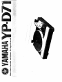
Yamaha thanks and congratulates you on your purchase of the YP-D71 stereo turntable unit. The YP-D71
uses a PLL circuit (phase·locked loop) with an integral quartz crystal oscillator for the servo control which
is the heart of a direct drive turntable. The yp·D71 represents the ultimate both in accuracy of the speed
of rotation and in realism of the reproduction which it gives.
It represents a combination of all Yamaha's tremendous resources in turntable-unit construction
technology: photo-electronic detection for the auto-up function, a high-sensitivity tonearm, heavy weight
turntable platter, and a cabinet in which resonances have been suppressed.
To ensure a long service life from your yp·D71, please read this owner's manual carefully.
Caution-Read This Before Operating
Your YP-D71 . . . . . . . . . . . . . . . . .
3
The Names and Functions of the Parts ..
4
Assembling the Turntable Unit. . . . . . .. 5
Assembl ing and Adjusting the Tonearm. .. 6
Assembling the Dust Cover and
Connections to Your Amplifier . . . . . , 8
How to Play Records. . . . . . . . . . . . . .. 9
Specifications
10
Trouble Shooting
11
IMPORTANT!
Please record the serial number of
your unit in the space below
IMOd"
L
N,m' YP-D71
]
Serial No.
The serial number is located on
the rear of the cabinet.
Retain this Owner's Manual in a
safe place for future reference.
fEATURES
Quartz Oscillator Phase-Locked Loop Control
This system (often abbreviated to Quartz PLL)
controls the speed of rotation of the motor by
using a quartz crystal oscillator, 'locking' it for a
dramatic increase in accuracy.
A Yamaha-Developed PLL IC
The integrated circuit (IC) used in the YP-D71
gives the highest possible accuracy in speed, with
freedom from temperature-induced drift. This
unique element was specially developed by
Yamaha.
Non-Contact Photo-Electronic Speed Detection
Auto-Up
As the cartridge stylus enters the innermost
groove, the tonearm lifts automatically and the
power is switched off.
The photo-electronic detector and the auto-up
circuit ensure smooth functioning.
Special Instructions for British-Standard Model
Heavyweight Turntable Platter and Mat
The turntable platter is heavy, 1.8 kg (4 Ib),
and has a high moment of inertia (230 kg-cm 2
including the rubber platter mat). This ensures the
minimum possible wow and flutter and smooth
rotation.
High-Sensitivity Tonearm
This highly sensitive S-shaped tonearm features
ideal lateral balance and uses a dynamic damping
system that together with a zinc die-cast arm base
holds resonance to a minimum. Excellent tracking
characteristics mean you hear all the music, with
out distortion.
IMPORTANT
THE WIRES IN THE MAINS LEAD ARE COL
OURED IN ACCORDANCE WITH THE FOL
LOWING CODE:
BLUE:
NEUTRAL
BROWN: LIVE
As the colours of the wires in the mains lead of this
apparatus may not correspond with the coloured
markings identifying the terminals in your plug,
proceed as follows.
The wire which is coloured BLUE must be con
nected to the terminal which is marked with the
letter N or coloured BLACK. The wire which is
coloured BROWN must be connected to the ter
minal which is marked with the letter L or col
oured RED.
2
L
I!IIIIl'I_lIl&ZlIIl!lilll~i1eil!li_~,\7.i\,"::"~:'"~~
- - - - - - - - - - - - - - - - - - - - - - - - - - - -....- - - - - - - - - - - - - - - - - - - - - - - - -- - - - • • • • • • • • • • • • • • • • • • •III• • •
~~$'AAr'0
W>
~
o
~
1
The YP-D71 is a sensitive piece of precision
audio equipment. For best results, read this
manual carefully before use.
2
Do not drop or jar the YP-D71, particularly
after it has been fully assembled and all
adjustments made. If it is accidentally
bumped, check all functions and readjust ac
cordingly.
3
When installing your YP-D71, avoid putting
the tonearm assembly on the same side as
the mains transformer of the audio amplifier.
4
Install the YP-D71 in a flat and level place,
out of the direct rays of the sun, and avoid
ing locations subject to vibration and exces
sive dust, heat, cold or moisture. Do not
place it directly in front of, or too close to
your speakers.
CAUTION-READ THIS BEFORE OPERATING YOUR VP-D71
5
9
When moving the YP-D71, use the original
packing and carefully re-pack it for transit.
Whichever high performance cartridge you
use with the YP-D71, be sure to keep the
stylus tip free from accumulated dirt: this is
the major single reason for poor quality
from records.
6
Do not attempt to clean it with chemical
solvents (such as alcohol or benzene). Wipe
only with a clean dry cloth.
7
10
The voltage selector switch on the bottom of
the YP-D71 must be set for your local mains
voltage BEFORE plugging in the AC main
supply. Voltages are 110/130/220/240 V
AC, 50/60 Hz. ( General Model only)
Voltage Selector Setting
When problems occur, consult the section on
'Trouble Shooting', which details common
operating errors.
.
8
Keep this manual in a safe place for future
reference, . and refer to it frequently until
you are familiar with your YP-D71.
.•.~
Warning:
to prevent fire or shock hazard,
do not expose this set to rain or moisture.
J
~
D
IJ
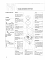
THE NAMES AND FUNCTIONS OF THE PARTS
THE NAMES OF THE PARTS
Rubber Mat
Tonearm
Specially designed to give ideal support for
records, damping their resonance and so
improving overall bass response.
The advanced S-shaped static balanced arm
used in the YP-D71 features special alumi
num alloy pipe and high sensitivitY gimbal
type supports, for top performance with all.
tYpes of cartridges.
ACCESSORIES
Turntable Platter
Inside Force Canceler
Roller Stand
Bias
Weight
Small
EP Adaptor Screwdriver
1~~!oiF,:11
I~"
I
Built of die-cast aluminum, it has been
specially dynamically balanced for optimum
flywheel smoothing effect, giving steady,
even rotation_
Armrest
Provides a secure rest for the tonearm
between record plaYings.
Dust Cover
Inside Force Canceler
The beautiful transparent acryl dust cover
is fully detachable by free-setting hinges for
maximum accessibility.
The hanging string-weight tYpe with a roller
allowing bias adjustment.
Center Shaft
The whole rna in weight assembly rotates
to give easy selection and clear indication of
accurate stYlus tracking force settings.
Main Weight
Main
Weight I
Dust Cover Hinge
Headshell
Cartridge - retaining screws
Cartridge - retaining nuts
Washers
In the YP-D71 the center shaft is integrated
with the motor and rotates at the actual
speed of the tur')table platter, reducing
vibration and eliminating the need for
intermediate mechanisms.
Lock Nut for Tonearm
When adjusting the height of the tonearm,
loosen this lock nut. After adjustment,
retighten the lock nut.
POWER/SPEED Switch
This switch serves
speed functions.
MOTOR/CUE Switch
Overhang Gauge
°r
I /'
".o.".e,!:,~~MAHA
power ON/OFF and
ON/33
OV'OHMVG GAUG'
,,,,,,,,,~,",o""""W"'''W',~..:::,:::,o
1(>
. Set this switch to ON/33 to play
a 33-1/3 r.p.m. disc.
OFF. . Set the switch to OFF position
when the turntable is not used.
When set to the OFF position,
the tonearm lifts and the turn
table stops.
ON/45 .. Set this switch to ON/45 to plaY
a 45 r.p.m. disc.
•
PLAY .. When set to this position, the
turntable starts rotating and the stylus
gently lowers itself onto the disc surface.
• CUT . . . Set the switch to this position
when yoll want to discontinue disc play.
The tonearm is lifted and the turntable is
stopped.
Headshell
LOCKED Indicator
This indicator lights up when the turntable
attains the correct and normal revolutions
and is loc ked by Quartz PLL
4
With gold-plated contacts for ultra-low con
tact resistance ensures of top quality phono
reproduction, this superior headshell accepts
virtually all cartridge types.
Insulator
These wide legs ins~late the YP-D71 from
vibrations and help to eliminate 'howling'
(acoust,c: feedback from speakers).
~lDllJ
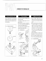
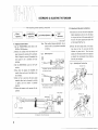
ASSEMBLING THE TURNTABLE UNIT
Take the turntable platter out from the protective
wrapping and gently place it onto the center shaft
as shown in Fig. 1. Place the rubber platter mat on
the turntable platter.
Fig. 1
Attaching the Turntable Platter
The YP-D71 comes without a cartridge. Choose a
high quality cartridge.
All cartridges with weights between 3 and 12
grams can be used.
When attaching the cartridge to the headshell, be
sure to join the leads from the cartridge to the
correct pins on the headshell. (See Fig. 2)
Ensure that the stylus tip overhangs the center·
spindle by 15mm, as shown in Fig.3.
Fig. 2
Headshell/Lead Wiring
Screw
I
t~
ri:A~!7\(
')
A~$J:I\IIBLlNGTfliT()NEARM'"
FITTINg ACARTR!J)(31: .
FITTING THE TURNTABLE PLATTER
~ ~
Washer.l
®
~.
iJ
1
T,,",,bl. 0 ",'"
1) Push the separately wrapped balance main
weight onto the rear of the tonearm, rotating it
at the same time in the direction shown (See
Fig. 4).
2) When the helicoidal groove on the inside of the
main weight
engages with the projecting
stopper on the front of the tonearm, further
rotation of the main weight in counterclock
wise direction (i,e. to the right when viewed
from the rear of the tonearm) draws the
main weight forward, and clockwise rotation
draws it backward.
To connect the headshell to the tonearm, insert
the headshell pin in a correct way into the slit on
the end of the tonearm and tighten the lock nut
firmly by turning it counterclockwise. (See Fig. 5)
,,-'>~: .. ---=-~
Cen ter shaft
~
//
~~~".
".~'/~ ~
~~~ ' " / : '.'
I.
.
•
_:'i,::...
' . /,' 2:J. /
-~~~~ , /
~~~'~.;//
Fig. 3
Overhang Adjustment -------~I
I
A
Overhang Gauge
Fit turntable shaft
into th'is hole.
It
,jj \
jj
This arrow must
point directly at
tonearm support,
~
5
Sl
WI~ ~
o
,
I
~
..
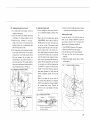
ASSEMBLING & ADJUSTING THE TONEARM
- - - - - - - After completing tonearm assembly, proceed with
1 balance
. adjustment,
[-'a..
tracking force
2. a d'Justmen t , ....
3. anti-skating adjustment,
..
(2) Adjusting cartridge stylus tracking force
4.
in that order
l
Note: When making balance adjustment, pay at
tention to the tip of needle as the turntable
is rotating.
(1) Adjusting tonearm balance
1) Set the POWER/SPEED switch either to the
ON/33 or ON/45 position.
2) Remove the tonearm from the armrest, and
keep it between the armrest and the tu rntable.
Raise (if hinged) or remove (if detachable) the
stylus guard if one is provided with your
cartridge.
Fig.6
Balance adjustment
X
\~-
3) Set the MOTOR/CUE switch to the PLAY
position.
4) Now check the balance: the headshell will
usually either tend to rise (if too light) or sink
(if too heavy).
5) Refer to Fig. 6, and move the main weight
assembly either back or forwards by rotating
it sl ightly until the tonearm is perfectly
balanced.
6) Replace the tonearm on the armrest after ad
justment.
height
adjustment,
~
~
1) Be careful not to move the main weight after
balance adjustment, and turn only the indica
tor ring on the front of the main weight until
the zero ('0') comes opposite the center line
on the tonearm (See Fig. 7-a).
2) Rotate the main weight slowly in the direc
tion shown in Fig. 7-b, and note that the
indicator ring turns with it. Turn the main
weight until the black hairl ine on the tonearm
is opposite the recommended stylus tracking
force for your cartridge.
Fig. 7
Adjusting Stylus Tracking Force
Indicator ring
Headshell is too heavy (rotate the main weight in
1_
,
the direction shown),
~
,
,
Main weight
,
Rear assembly is too heavy (rotate the main weight
in the direction shown!'
/'
Main weight
Indicator line
( b )
I
Headshell
Configuration for perfect balance
6
------------------------~--'"
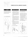
(3) Adjusting the Inside Force Canceler
1) To install Inside Force Canceler, secure the
tonearm to the arm rest.
2) Insert the Inside Force Canceler roller stand,
an accessory, into the post as shown in Fig. 8.
3) Hang the string, connected to the bi as
weight, over a groove on the bias lever (this
hangi ng position will be adjusted later) and
place the string over the roller.
4} The stri ng position on the bias lever is decided
by the stylus tracking force. The first groove
corresponds to 19 and other grooves provide
O.5g step increases, the end groove thus
corresponding to 2.5g. Select the groove to
meet your stylus force. For example, hang the
string over the third groove (from the end) for
1.5g cartridge stylus force. (See Fig. 9).
(4) Adjusting tonearm height
1} If your cartridge has a stylus guard, remove it:
if it is permanently hinged in position, lift it
up.
2} Place a disc on the turntable platter. Set the
POWER/SPEED switch either to ON/33 or
ON/45 position, then lower the stylus tip on
to the disc surface. If the tonearm is found
failing to parallel the disc surface at this time,
puts the tonearm back to the armrest once.
And, while keeping the tonearm in the arm
rest, loosen the arm-base lock nut, and gently
move the tonearm proper (upward or down
ward) so that it becomes parallel with the disc
surface. After this adjustment, place the stylus
tip once again on to the disc surface and see
if parallelism in question has been attained.
Should it be still found otherwise, repeat the
above same adjustment to finally bring the
tonearm completely parallel with the disc
surface.
Make sure to tighten the lock nut firmly to
the arm-base when adjustment is completed.
NOTE: During adjustment of tonearm height,
the turntable keeps turning. Therefore, be
careful so as not to give damage to the stylus
tip or a disc.
3} Once the tonearm height adjustment has been
completed, secure the tonearm to the armrest.
Adjusting stylus height
In case the position of the stylus tip comes to
differ due to cartridge replacement, adjust the
stylus height as shown in Fig. 11 by means of the
adjusting screw and accessory screwdriver.
Turn MOTOR/CUE switch to CUT position.
Bring the tonearm over the disc surface.
To raise the stylus, turn the screw clockwise.
To lower the stylus, turn the screw counter
clockwise.
5) Adjust stylus height between 4mm to 10mm
with this screw.
1}
2)
3)
4)
Fig. 11
Adjusting the Height of the Stylus
HII
Fig. 10 Adjusting tonearm height
Tonearm
Arm-base lock nut
~
~~ I
?~
,
~
,
I
The.tonearm should be parallel
with the disc surface.
.,
~
l
D
ASSEMBLING THE DUST COVER & CONNECTIONS TO YOUR AMPLIFIER
DusrCOVER
CONNECTIONS TO YOUR AMPLIFIER
TIMING ADJUSTMENT ON.AUrO·Up
The dust cover can be freely attached and de
tached. When attaching, follow directions in Fig.
1) The output leads projecting from the rear of
the cabinet should be connected to the
PHONO input terminals on your audio ampli
fier. Ensure the left- and right-hand channels
are connected correctly. The white lead is the
left, and the red lead the right channel. (See
Fig. 13).
Please avoid unnecessary adjustment on Auto-up
as it is factory-adjusted b~fore shipment.
12, ensuring that the stud fits securely into the
grooves as shown. Reverse to detach.
Fig. 12
"
Attaching and Detaching the Dust Cover
~,
//'~"\,,,
~
.
~I',,',
T~
..~
o;",~"
~.
.
H;""
~'CD
,,~CV
///><
The dust cover will remain open at an angle of 40
degrees or larger.
'8
2) The black ground lead issuing from the output
leads should be connected to the GND
(ground) terminal on your amplifier (see Fig.
13). Certain amplifiers have less hum and
noise when no ground connection is made:
employ whichever gives the lower hum and
noise levels.
3) Insert the AC plug of the YP-D71 either into a
wall AC supply socket, or into a spare AC
outlet socket, if one is provided, on the rear
of your amplifier. If the latter, it is better to
use an unswitched socket.
Fig. 13
Connections to an Audio Amplifier
~o
p~O
White
G~O l,.QJ~
r~~
... i.... -.
~
.~
~~~/
If the Auto-up timing is off, adjust by means of
the adjusting screw and the accessory screw driver.
1) Secure the tonearm to the armrest and remove
the ru bber cap from the adjusting screw.
2) If Auto-up takes place before disc play finishes,
turn the adjusting screw clockwise.
3) If the tonearm remains on the disc even after
the finish of the disc play, turn the adjusting
screw counter-clockwise.
Note: This adjusting screw allows two-step shift
ing both in the right and left directions.
Fig. 14
I1III1
~ In ~
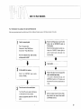
HOW TO PLAY RECORDS
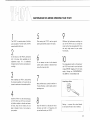
PLAY RECORDS BY FOLLOWING THE INSTRUCTIONS BELOW.
After having completed assembly and adjustment of the turntable and tonearm, carry out the following steps in this order.
1
Check
th~
4
connecting leads.
Plug -4- AC supply socket
Output lead -4- Amp. PHONO jacks
Ground lead -4- Amp. GNDterminal
Have all connections been made correctly
and plugs pushed in tight?
2
•
•
+
~
L
5 R.eo,d .od;oo ..•~ ...
I
Set the amplifier for operation.
Switch the FUNCTION
switch) to PHONO.
3
Bring the cartridge stylus tip over the disc
surface, and set MOTOR/CUE switch to
P LAY position.
When the tu'rntable reaches the normal revo
lutions, the "LOCKED" indicator lights on
and the tonearm lowers itself gently onto
the disc surface.
(input
selector
6
Place the record on the turntable platter.
For 45 rpm EP records, place the EP adaptor
on the center shaft of the turntable.
Select the appropriate speed (45 or 33-1/3
rpm).
"
(I)
7
When the disc play is over, the tonearm lifts
and the turntable stops turning.
If you want to discontinue disc play, turn
MOTOR/CUE switch to CUT position, and
the tonearm lifts and the turntable comes to
a stop.
+
After the tonearm leaves the disc surface,
bring it back to the armrest. Always switch
to OFF when not in use.
9
VIu ~jo ~~ ffu
SPECifiCATIONS
GENERAL
TURNTABLE MOTOR SECTION
Power Supplies
Drive System
Direct drive
Motor
Careless DC Hall Motor
Servo System
....... _._
Quartz Locked (PLL)
----------
~-'-
120V AC, 60 Hz (U.S. & Canadian Models)
nov
AC, 50 Hz (European Model)
.
-- - - - - - - - _ . '
~--_._
.. _ - - - - - _ . _ ..•. _...
240V AC, 50 Hz (British & Australian
..
Models)
Start up Torque
1 kg·cm
Turntable Platter
31 em (12-1/4"1 die-cast aluminum.
110/130/220/240V AC, 50/60 Hz (General
Weight, 1.8
Model)
.
--
2~?l<g~cm2 includingrubber platter mat.
Power Consumption
Speed
33-1/3, 45r.p.m.(with quartz locked-indicator!
Cabinet
Wow and Flutter
0.025% (WRMS), ±0.035% peak (IEC 98A
------
"
.....
-
--~_._--_
.. _
.. _._----
13W
------.--------_.
--~--,_._.-
U.S. & Canadian Models
-_. ' - - - _ . -
----------_._.'"._~-------
_.' .. - - - _ . __ ..
Ebony Particle board with polyvinyl chloride
~_
.. -... _. __ ....-
weighted
Signal-to-Noise Ratio
-
--,---.-----_.
---------,._------
finish
77 dB (I EC 98A weiahted)
American Walnut Particle board with polyvinyl
Other Area Models
chloride finish
TONEARM SECTION
Arm Type
Tonearm Total Length
Tonearm Effective Length
Dust Cover
S-shaped static balanced arm with gimbal
Hinges
Free-setting, detachable
supports
Acoustic Insulators
Large double-folded insulators
318 mm (12-1/2")
._ ... _----_.---_.
Off-set angle
.............................
21
Weight
-- ---_.- ....
__
.
._.-..
-
..................................•
470 x 150 x 373 mm
_-
-- -----.'---,_..
_-
(18-1/2" x 6" x 14-11/16")
..."-
------------'----,.
-----_._-~----_.-
11 kg (24Ibs4oz)
..
-
--'--
..
__
.,---"--~----
15'
Stylus Tip Equivalent Mass
15 g
Tracking Error Angle
+2 b30~-=-1°
...............................
-
'--'---"-
-,
15 mm
Inside Force Canceler
- . - - _ . _ ..
Dimensions (W x H x D)
--
242 mm (9-1/2")
., .."-- - - - - - ' -
Overhang
Tonearm Stand Base
Acryl
Die-cast zinc
.
.
String/weight Hanging type
Height Adjust
±4mm
_.-
Tracking Force
Counter Ring type 0.25 g step
Cueing
Oil damping type
Auto-Up Stop
Non-contact photo-electronic speed detector,
.•.......
-
-_.
,,-----,---
-'
linked with cueing mechanism and power ON/
OFF switch.
Headshell
Forged pure aluminum (interchangeable to
EIA standard: weight 9
Possible Cartridge Weights
3
Output Leads
NEG LEX 2496 Low Impedance biaxial cable
~
12 g
Specifications subject to change without notice_
j
I
'
-
.
~
-
O
;
:
_
.
~
;
:
l
!
i
_________
i
10"
~
u o
TROUBLE SHOOTING
If your YP-D71 malfunctions, first check the following trouble-shooting list. If this fails to correct the problem, contact your local Yamaha
dealer or service representative.
--
--Cause
Fault
-----
.
~-_
..
__. _ - - - - - - ........... _... _.__
.----,-~-,_._.,-,
.....
Turntable does not rotate, although switch is set ON.
---_._-
_._--- .
_... _.. _._._--_.
__
._._---~~._.,,'-
Mains supply plug not firmly plugged into supply socket.
Push plug firmly into the socket.
The cartridge is either too heavy or too light.
Repeat the adjustment with the main weight either further
forward or bac k.
.._.
Balance cannot be obtained after changing cartridge.
__
_
... ..........._-----".
. ... _--_.
----,..
Cure
._
There is no sound although the stylus descends to
the record surface.
...
.. -
Headshell connections faulty.
Polish the connector pins with a soft cloth.
Amplifier function not set to PHONO.
Set the function control to PHONO.
.' .. - _..... _...
_---_._---_._-~------
...
_.
-- ------
-_._-
--
Amplifier volume too low.
Raise the volume slowly.
--------
I
urntaDle unit output leads not properly connected.
Check the connections at the rear panel of the amplifier.
------
The body of the cartridge catches on the record
surface.
--_ ..._--
Stylus tracking force too high.
Check and readjust for correct stylus t racking force.
------_._-------~-.---_.-
Tonearm height is wrong.
Adjust the tonearm height correctly.
Dust and dirt has accumulated on the stylus tip.
Wipe the stylus tip clean with the special stylus cleaning
brush provided with the accessories.
.. -_._.
The reproduced sound is distorted, with clicking or
scraping sounds. High frequency reproduction is par
ticularly affected.
The stylus tip is worn.
Replace the stylus.
The record itself is damaged, or is dirty.
Replace with a new record.
Stylus tracking force is either too little or too great.
Readjust the tracking force for the car tridge to the
recommended value.
Amplifier treble response has been overemphasized.
Turn the treble control back to the fla tposition.
_...... _ . _ - - - _ . _ - _ .. _
-----
--
~_
..
_----._---~
.._----------
.-_ ....
_-
When installing the YP-D71, never fail to keep th.e level. If not, the rotation of motor
and the movement of tonearm will be adversely affected.
1 '1,,
1
::.::
<l:
a
z
oa..
a..
Z