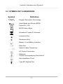
1
Model 900
Pulse Oximeter User’s Manual
MEDIAID INC.
17517 Fabrica Way Suite H, Cerritos, CA 90703 USA
Phone: 714-367-2848; Fax: 714-367-2852
Website: www.mediaidinc.com
POX010-900
Contents
Table of Contents
Chapter 1: Safety Information
1.1 GENERAL SAFETY INFORMATION ................................................ 1
Chapter 2: Introduction
2.1 INTENDED USE ................................................................................... 3
2.2 GENERAL OPERATING PRINCIPLES & CONDITIONS ................ 3
Chapter 3: Controls, Indicators and Symbols
3.1 DISPLAYS, CONTROLS, INDICATORS & CONNECTORS ............ 5
3.2 SYMBOLOGY & MARKINGS ............................................................ 7
3.3 DESCRIPTION OF CONTROLS & CONNECTORS ........................ 8
A. Po wer ON /OFF Key .............................................................
B. Po wer ON /OFF Swi tch ........................................................
C. Senso r Cable Connection ....................................................
D. Po wer In let .........................................................................
E. Da ta Port ............................................................................
F. A larm Mute Key ..................................................................
G. F reeze / Unf reeze Key ........................................................
H. Up Key & Do wn Key ............................................................
I. Sof t Func tion Keys ...............................................................
8
8
8
9
9
9
9
9
9
3.4 DESCRIPTION OF DISPLAYS & INDICATORS ............................ 10
A. Oxygen Satu ra tion Display ................................................
B. Pu lse Ra te Display ...........................................................
C. Graph ic LCD D isplay ........................................................
D. Ba tte ry Opera tion Ind icato r ...............................................
E. Ba tte ry Lo w Indicato r ........................................................
F. AC Powe r Indica tor ...........................................................
G. Ala rm Mute Ind icato r ........................................................
-
Contents 1 -
11
11
11
11
11
11
11
Contents
3.5 DESCRIPTION OF AUDIBLE ALARMS & INDICATORS ............. 11
High o r Low Oxygen Satu rat ion Leve ls ..................................
High o r Low Pu lse Ra te Levels ..............................................
Low Perfusion .......................................................................
No Pulse ...............................................................................
No Finge r in Senso r ..............................................................
No Sensor / D isconnected Senso r .........................................
Power-On Aud io Indica tor ......................................................
Pulse Beep Audio Ind icato r ...................................................
11
11
11
12
12
12
12
12
Chapter 4: Set Up
4.1 UNPACKING & INSPECTION ......................................................... 13
4.2 LIST OF COMPONENTS .................................................................. 13
4.3 OXIMETER SETUP ........................................................................... 13
General Wa rnings .................................................................
Connecting the Model 900 to A C Po wer .................................
Operat ing on a Discharged Bat te ry ........................................
Sett ing Up ............................................................................
13
14
15
15
Chapter 5: Sensors
5.1 SELECTING A SENSOR .................................................................. 17
5.2 BIOCOMPATIBILTY TESTING ........................................................ 19
5.3 PERFORMANCE CONSIDERATIONS ........................................... 19
Inaccurate Measu rements ..................................................... 19
Loss of Pu lse S ignal .............................................................. 19
Use Only Med iaid Sensors and Sensor Cab les ....................... 19
Chapter 6: Start Up and Use
6.1 BASIC OPERATION ......................................................................... 21
Power-On .............................................................................
Adult , Ped iat ric and Neona tal Set tings ...................................
Contras t ................................................................................
Monito ring Mode ...................................................................
Pulse Sea rch ........................................................................
-
Contents 2 -
22
24
24
24
25
Contents
At Ini tia l Powe r-Up (Senso r A ttached to Oxi mete r) .................
At Ini tia l Powe r-Up (No Sensor At tached to Oxime te r) ............
Afte r Tak ing Measuremen ts ...................................................
Sensor D isconnected a t Oxime ter End ...................................
Sensor D isconnected a t Pa tien t End ......................................
25
25
26
26
26
6.2 DIAGNOSTIC TEST .......................................................................... 26
6.3 ALARMS ............................................................................................ 27
High o r Low Oxygen Satu rat ion Leve ls ..................................
High o r Low Pu lse Ra te Levels ..............................................
Low Perfusion ........................................................................
No Pulse ................................................................................
No Finge r in Senso r ...............................................................
No Sensor / D isconnected Senso r ..........................................
27
27
27
28
28
28
6.4 ADJUSTABLE SETTINGS ............................................................... 28
Pulse Beep Volume ...............................................................
Alarm Vo lume .......................................................................
Alarm Mu te ............................................................................
Disabling Audib le Ala rms .......................................................
28
28
29
29
6.5 MENU ................................................................................................. 30
Menu S truc ture ..................................................................... 30
6.6 LIMITS ................................................................................................ 30
Overview ..............................................................................
Viewing Cu rren t A larm L im its ................................................
Changing A larm L imi ts ..........................................................
Power-On Fac tory Defau lt A larm Li mi ts .................................
30
31
31
31
6.7 TREND ............................................................................................... 33
Scale .................................................................................... 33
Delete ................................................................................... 34
6.8 SETUP ................................................................................................ 34
Time .....................................................................................
Date .....................................................................................
Nurse Ca ll ............................................................................
Analog ..................................................................................
Back Light ............................................................................
Defaul t Se tt ings ....................................................................
34
34
35
36
36
36
6.9 BATTERY OPERATION ................................................................... 38
Low Bat tery Ind icato r ............................................................. 38
6.10 DISPOSAL OF DEVICE COMPONENTS ..................................... 39
-
Contents 3 -
Contents
6.11 PERFORMANCE CONSIDERATIONS ......................................... 39
Impact of Pa tient Cond it ions on Oxime te r Read ings ............... 39
Inaccurate Measu rements ....................................................... 39
Chapter 7: Troubleshooting and Maintenance
7.1 TROUBLE SHOOTING ..................................................................... 41
Erro r Codes .......................................................................... 41
Other Messages .................................................................... 42
Suggested Co rrec tive Act ions ................................................ 42
7.2 EMI (ELECTROMAGNETIC INTEFERENCE) ............................... 44
7.3 OBTAINING TECHNICAL ASSISTANCE ....................................... 45
Return ing the Model 900 ....................................................... 46
7.4 MAINTENANCE ................................................................................ 46
Service .................................................................................
Period ic Sa fety Checks .........................................................
Perfo rmance Verif icat ion .......................................................
Cleaning ...............................................................................
46
46
46
47
Chapter 8: Specifications
8.1 SPECIFICATIONS ............................................................................. 49
Perfo rmance .........................................................................
Elect rical ..............................................................................
Sensor ...................................................................................
Environmen tal Condi tions ......................................................
Physical Cha racte ris tics .........................................................
Compliance ...........................................................................
49
49
50
50
50
51
Chapter 9: Quick Guide to Operations
9.1 QUICK GUIDE TO OPERATIONS ................................................... 53
Int roduction .......................................................................... 53
Sett ings Ad justmen ts ............................................................ 53
-
Contents 4 -
Contents
Chapter 10: Principles of Operation
10. 1 OXIMETRY OVERVIEW ................................................................ 55
How Pulse Ox imete rs Wo rk ...................................................
Calib rat ion o f Pu lse Ox ime ters ..............................................
Valida tion o f Accuracy ...........................................................
Clin ical Use of Pu lse Ox ime try ..............................................
55
57
57
58
Chapter 11: Data Port Protocol
11.1 DATA PORT PROTOCOL .............................................................. 59
Overview .............................................................................. 59
Seria l Da ta T ransm ission ...................................................... 59
11.2 NURSE CALL .................................................................................. 61
11.3 ANALOG OUTPUTS ....................................................................... 62
Chapter 12: Warranty Information
12.1 MEDIAID INC. WARRANTY INFORMATION ...................... 65
Applicat ion o f Wa rran ty ......................................................... 65
What is cove red by th is Warranty? ........................................ 65
What Media id wil l do to correct the p roblems? ....................... 65
12.2 OWNER’S REGISTRATION .......................................................... 66
Product In format ion ............................................................... 67
-
Contents 5 -
Safety Information
Chapter 1:
Safety Information
1.1 GENERAL SAFETY INFORMATION
This section contains important safety information related to general use
of the Model 900 pulse oximeter. Other important safety information
appears throughout the manual in sections that relate specifically to the
precautionary information.
Important!! Before using the pulse oximeter, the user should become
thoroughly familiar with the information in this manual and with all
information included with the sensor.
WARNING
Explosion hazard. Do not
use the Model 900 pulse
oximeter in the presence of
flammable anesthetics or
gases.
WARNING
The Model 900 is a
prescription device and is
to be operated by qualified
personnel only.
WARNING
Chemicals from broken LCD display panel are toxic when
ingested. Use caution when handling an oximeter with a
broken display panel.
WARNING
Pulse oximeter readings and pulse signal can be affected
by certain ambient environmental conditions, sensor
application errors, and certain patient conditions. See the
appropriate sections of the manual for specific safety
information.
-1-
Safety Information
CAUTION
When connecting the Model 900 to any instrument, verify proper
operation before clinical use. Both the Model 900 and the instrument
connected to it must be grounded properly. Accessory equipment
connected to the oximeter’s data interface must be certified
according to IEC Standard 950 for data-processing equipment or
IEC Standard 60601-1 for electro medical equipment. All
combinations of equipment must be in compliance with IEC
Standard 60601-1 systems requirements. Anyone who connects
additional equipment to the signal input port or signal output port
(Model 900 data port connector) configures a medical system and is
therefore responsible for ensuring that the system complies with the
requirements of system standard IEC Standard 60601-1 and the
electromagnetic compatibility system standard IEC Standard 606011-2. The Model 900 accuracy may degrade if it is connected to
secondary I/O devices when the instrument is not connected to
earth reference.
To ensure accurate readings, consider the environment conditions that
are present and the condition of the patient. See the appropriate sections
of the manual for specific safety information related to these conditions.
-2-
Introduction
Chapter 2:
Introduction
2.1 INTENDED USE
The Model 900 is a portable pulse oximeter intended for use as a
continuous noninvasive oximeter of functional oxygen saturation of
arterial hemoglobin (SpO2) and pulse rate. The intended patient
population comprises adult, pediatric, and neonatal patients. The
intended environments of use are hospitals, hospital type facilities, intrahospital transport environments and home care. The Model 900 is for
prescription use only. Hospital use typically covers such areas as
general care floors, operating rooms,
special procedure areas, intensive
WARNING
The Model 900 is intended
and critical care areas within the
only as an adjunct in patient
hospital plus hospital-type facilities
assessment. It must be used
such as surgical centers, sub-acute
in conjunction with clinical
centers, special nursing facilities and
signs and symptoms.
sleep labs, outside of the hospital.
.
Intra-hospital transport includes transport of a patient within the hospital
or hospital-type facility.
2.2 GENERAL OPERATING PRINCIPLES AND
CONDITIONS
The Model 900 uses pulse oximeter to measure functional oxygen
saturation in the blood. Pulse oximeter works by applying a sensor to a
pulsating arteriolar vascular bed, such as a finger or toe. The sensor
contains a dual light source and a photodetector.
Bone, tissue, pigmentation and venous vessels normally absorb
a constant amount of light over time. The arteriolar bed normally pulsates
and absorbs variable amounts of light during the pulsations. The ratio of
-3-
Introduction
light absorbed is translated into a measurement of functional oxygen
saturation (SpO2).
Since the measurement of SpO2 is dependent upon light from the
sensor, excessive ambient light can interfere with this measurement.
Specific information about ambient environment conditions, sensor
application and patient conditions is contained throughout this manual.
-4-
Controls, Indicators and Symbols
Chapter 3:
Controls, Indicators and
Symbols
3.1 DISPLAYS, CONTROLS, INDICATORS AND
CONNECTORS
Figure 1,2 and 3 show the front, rear and side views of the Model 900
and identify displays, controls and connectors.
Figure 1: Model 900 Front Panel Display (Pleth View)
A
Power On/Off Key
H
B
%SpO 2 Display (Green)
I
AC Power Indicator (Green)
C
Pleth Waveform Display
J
Battery Operation Indicator
(Orange)
D
Freeze / Unfreeze Key
K
Battery Low Indicator (Red)
E
UP Key
L
Soft Function Keys
F
MUTE Key
M
Pulse Rate Display (Red)
G
Alarm MUTE Indicator
(Red)
-5-
DOWN Key
Controls, Indicators and Symbols
Figure 2: Model 900 Rear Panel
N AC Power Inlet Q Data Port Connector O Fuse Receptacle R Speaker
P AC / Battery Power ON Switch
Figure 3: Model 900 Left Side Panel
-6-
S SpO2 Sensor Port
Controls, Indicators and Symbols
3.2 SYMBOLOGY & MARKINGS
Symbol
%SpO2
Definition
Oxygen Saturation Percentage
Heart Beats per Minute (BPM)
Power On / Off
MUTE Alarm Mute
Waveform Freeze & Unfreeze
Increment Key
Decrement Key
Battery / Low Battery Indicator
Data Port
Sensor Cable Connection
AC Power Connection
Attention:
Consult Accompanying Documents
Non-anesthetic Proof
Type BF Applied Part
-7-
Controls, Indicators and Symbols
3.3 DESCRIPTION OF CONTROLS & CONNECTORS
A. Power ON/OFF Key
The unit is powered on with a short depression of the POWER ON/OFF
KEY. A long beep sound followed by a three (3)-seconds display,
indicator test and self test is performed automatically. All Light Emitting
Diodes (LED’s) and the LCD backlight, are illuminated. Carefully observe
the Saturation and Pulse Rate LED displays for proper operation of all
segments of the display; a non-functioning segment will result in an
incomplete numeral and possible erroneous reading.
B. Power ON/OFF Switch
The POWER ON/OFF SWITCH is located at the back of the oximeter
below the AC POWER INLET port. When this Switch is turned Off the
oximeter gets totally isolated from the AC power and the battery power.
When this Switch is turned On, the oximeter gets powered from AC
Mains, when it is connected to AC Mains, else it gets powered by
battery.
C. Sensor Cable Connection
All Mediaid pulse oximeter sensors with Compushield connectors are
compatible with the Model 900. To connect a sensor to the oximeter,
align the sensor plug with the jack on the oximeter sensor port and insert
gently until an audible “click” is heard, indicating that the plug tab is
latched in place. To remove, squeeze the locking tab on the plug and
slide the plug out of the jack. Always route cords in such a way so as to
prevent accidental tripping and subsequent damage to the oximeter.
D. Power Inlet
For electric power, plug the AC power cord into the AC POWER INLET
on the rear panel of the oximeter and then plug the other end of cord into
a standard electrical outlet.
-8-
Controls, Indicators and Symbols
E. Data Port
The DATA PORT is used for serial, analog output and for Nurse Call
feature. To eliminate risk of shock, take care not to touch the DATA
PORT 15-pin Connector and the patient simultaneously. The DATA
PORT should be used only for connection to equipment that complies
with CSA/IEC/UL601-1.
F. Alarm Mute Key
The ALARM MUTE KEY will be operational only when any oximeter
alarm is activated. A short depression of this key silences the alarm for a
period of 60 seconds. The ALARM MUTE indicator in the LCD screen (a
crossed speaker symbol) will be displayed and the ALARM MUTE
indicator LED will glow. Silenced alarms can be reactivated by a short
depression of the ALARM MUTE KEY. A long, three-second depression
of the key will completely disable the audible alarm till the next Power up.
The ALARM MUTE in the LCD screen (a crossed speaker symbol) will
begin to flash and the ALARM MUTE indicator LED will glow. Disabled
alarms are reactivated by a long depression of the ALARM MUTE KEY.
Also the Silenced & Disabled alarms will be reactivated as soon as a
fresh alarm condition is generated.
G. Freeze/Unfreeze Key
The FREEZE/UNFREEZE KEY is used to freeze and unfreeze the
plethysmographic waveform on the graphic LCD display.
H. Up Key & Down Key
The pulse tone volumes can be adjusted using the UP and DOWN keys.
There are five
(5) levels of audible (pulse) tone volume, and “Off”. The pulse tone
volume can be increased with the UP key, and decreased or silenced
with the DOWN key. These keys are also used to adjust the Alarm limits,
alarm volume, contrast, patient type, date & time values, and to move the
cursor in the menu / trend view.
I. Soft Function Keys
The three SOFT FUNCTION KEYS have multiple uses depending on the
legend displayed in the LCD screen above the key.
-9-
Controls, Indicators and Symbols
3.4 DESCRIPTION OF DISPLAYS & INDICATORS
A. Oxygen Saturation Display
Whenever the pulse oximeter receives at least three (3) valid pulses
during a 15-second period, the top green LEDs display the patient’s
%SpO2 levels. The display is updated with every normal pulse. A blinking
display signals that %SpO2 monitoring may be adversely affected and
indicates that the %SpO2 levels are out of alarm limits. Dashes “- - - “ are
displayed under conditions of No Sensor, No Finger, No Pulse and
Searching (signal). Blinking Dashes “- - - “ are displayed under Low
Perfusion condition. “Err” is displayed when there is a hardware error in
the oximeter, to indicate an Error.
B. Pulse Rate Display
Whenever the pulse oximeter receives at least three (3) valid pulses
during a 15-second period, the bottom red LEDs display the patient’s
Pulse Rate levels in beats-per-minute. The display is updated with every
normal pulse. A blinking display signals that Pulse Rate monitoring may
be adversely affected and indicates that the Pulse Rate levels are out of
alarm limits. Dashes “- - - “ are displayed under conditions of No Sensor,
No Finger, No Pulse and Searching (signal). Blinking Dashes “- - - “ are
displayed under Low Perfusion condition. The Error Code is displayed
when there is a hardware error in the oximeter, to indicate an Error.
C. Graphic LCD Display
The GRAPHIC LCD DISPLAY has multiple uses depending on the
current mode. In the normal operation whenever the pulse oximeter
receives at least three (3) valid pulses during a 15-second period, the
plethysmographic waveform is displayed. It also displays Visual Alarms;
Searching (for signal); Patient type ; Beep volume level; Alarm Mute
status; Battery-charge status; Date & Time details; Function Key labels
including Menu Settings, Trend Data and Back light.
D. Battery Operation Indicator
The orange LED for Battery Operation Indication will illuminate when the
oximeter is being operated on battery.
- 10 -
Controls, Indicators and Symbols
E. Battery Low Indicator
The red LED for Battery Low Indication will illuminate when the battery is
near depletion, prompting the user to suspend operation of the unit and
recharge/change the battery. The oximeter will power off shortly after
Battery Low Indication.
F. AC Power Indicator
The green LED for AC Power Indication, located above the BATTERY
INDICATORS will illuminate when the oximeter is being powered by AC
power. It also indicates that the battery is charging. It is off when the
oximeter is being powered by its internal battery.
G. Alarm Mute Indicator
The ALARM MUTE INDICATOR will illuminate and remain on constantly
when audible alarms are silenced or disabled.
3.5 DESCRIPTION OF AUDIBLE ALARMS
& INDICATORS
A high-pitched, beep-beep tone alarm is activated under the following
Alarm conditions:
High or Low Oxygen Saturation Levels
When the high or low Oxygen Saturation levels are breached, a beep
alarm along with a blinking SpO2 display and “SAT-HIGH” or “SAT-LOW”
visual indicator is displayed in the graphical LCD display.
High or Low Pulse Rate Levels
When the high or low Pulse Rate levels are breached, a beep alarm
along with a blinking SpO2 display and “BPM-HIGH” or “BPM-LOW”
visual indicator is displayed in the graphical LCD display.
Low Perfusion
Under the low perfusion condition, a beep alarm along with blinking
Dashes “- - - “ in the %SpO2 & Pulse Rate displays and a “LOW PERF”
visual indicator is displayed in the graphical LCD display.
- 11 -
Controls, Indicators and Symbols
No Pulse
When the oximeter does not detect a valid pluse after searching for
approximately 45 seconds and no valid pulse signal is detected, Dashes
“- - - “ in the %SpO2 & Pulse Rate displays are indicated and “NO
PULSE” visual indicator is displayed in the graphical LCD display.
No Finger in Sensor
When there is no finger in the sensor, beep alarm along with Dashes “- - “ in the %SpO2 & Pulse Rate displays and a blinking “NO FINGER”
visual indicator is displayed in the graphical LCD display.
No Sensor / Disconnected Sensor
When the sensor is removed, disconnected or not inserted in the
oximeter, beep alarm is sounded along with Dashes “- - - “ in the %SpO2
& Pulse Rate displays and a blinking “NO SENSOR” visual indicator is
displayed in the graphical LCD display.
Power-On Audio Indicator
When the oximeter is powered on with the press of the POWER ON/OFF
Key, a long beep indicating that the oximeter is powered on.
Pulse Beep Audio Indicator
A single beep sounds for each detected valid pulse that varies in pitch
with changing oxygen saturation, falling in pitch with reduced saturation
and rising as saturation increases.
- 12 -
Setup
Chapter 4:
Setup
4.1 UNPACKING AND INSPECTION
Notify the carrier if the shipping carton is damaged. Unpack the Model
900 and components. If anything is missing as per the List of
Components or damaged, contact Mediaid Inc. or the Mediaid local
authorized distributor.
4.2 LIST OF COMPONENTS
1.
2.
3.
4.
5.
Model 900 Pulse Oximeter
Mediaid Reusable sensor
Model 900 User’s Manual
AC Power Cord
Additional Accessories as ordered, if any
4.3 OXIMETER SETUP
General Warnings
WARNING
To ensure patient safety, do not place the oximeter in any position that might
cause it to fall on the patient.
WARNING
As with all medical equipment, carefully route patient cabling to reduce the
possibility of patient entanglement or strangulation.
- 13 -
Setup
WARNING
To ensure accurate performance and prevent device failure, do not subject
the Model 900 to extreme moisture, such as direct exposure to rain. Such
exposure may cause inaccurate performance or device failure.
WARNING
Disconnect the Model 900 and Mediaid sensor from the patient during
magnetic resonance imaging (MRI) scanning. Induced current could
potentially cause burns. The Model 900 may affect the MRI image and the
MRI unit may affect the accuracy of oximeter measurements.
WARNING
Do not use a Model 900 oximeter, AC Power cord, sensor, sensor cable or
connector that appear to be damaged.
WARNING
The Model 900 is not defibrillator-proof. However, it may remain attached to
the patient during defibrillation or while an electrosurgical unit is in use, but
the readings may be inaccurate during use and shortly thereafter.
Connecting the Model 900 to AC Power
The POWER ON/OFF SWITCH is located at the back of the oximeter
below the AC POWER INLET port. When this Switch is turned Off the
oximeter gets totally isolated from the AC power and the battery power.
When this Switch is turned On, the oximeter gets powered from AC
Mains, when it is connected to AC Mains, else it gets powered by
battery.
The Model 900 operates on AC power when the oximeter is connected to
the AC power source (wall outlet) with a power cord.
- 14 -
Setup
Operating on a Discharged Battery
The battery may discharge during prolonged storage or shipment. If the
oximeter has been in storage for more than 2 months, it is advisable to
plug the oximeter into an AC outlet and allow the battery to charge for
approximately 45 minutes before attempting to operate the instrument on
AC power.
To charge a low battery, connect the oximeter to AC power. A full charge
of a completely discharged battery takes approximately 16 hours while
the oximeter is turned off and it takes approximately 20 hours while the
oximeter is turned on.
Setting Up
•
Place the Model 900 on a flat surface near the patient.
•
Plug the female connector end of the power cord into the rear of the
oximeter. Use only the AC power cord provided by Mediaid.
•
Plug the male connector end of the power cord into a properly
grounded AC outlet.
•
Switch on the POWER ON/OFF SWITCH located at the rear side of
the oximeter.
•
Verify that the AC POWER INDICATOR is lit. If it is not, ensure that
the POWER ON/OFF SWITCH is in the “ON” position. If the indicator
still does not light, check the local AC power at the wall outlet. If the
problem still persists, contact Mediaid Inc. or the Mediaid local
authorized distributor/service center.
•
Select a Mediaid sensor appropriate for the patient to be monitored
(see the Sensors section of this manual for sensor selection
information).
- 15 -
Principe d’Utilisation
- 16 -
Sensors
Chapter 5:
Sensors
5.1 SELECTING A SENSOR
WARNING
Before use, carefully read the sensor directions for use, including
all warnings, cautions and instructions.
WARNING
Use only Mediaid sensors and sensor cables with this oximeter.
Other sensors or sensor cables may cause improper Model 900
performance
WARNING
Do not use a damaged sensor or sensor cable. Do not use a
sensor with exposed optical components.
WARNING
Do not attach any cable intended for other use, to the Model 900
sensor port.
WARNING
Tissue damage can be caused by incorrect applications or
duration of use of a SpO2 sensor. Inspect the sensor site
periodically as directed in the sensor directions for use.
When selecting a sensor, consider the patient’s weight and activity level,
the adequacy or perfusion, the available sensor sites, the need for
sterility, and the anticipated duration of monitoring. For more information,
refer to Table 1 or contact Mediaid Inc. or the Mediaid local authorized
distributor.
- 17 -
Sensors
TABLE 1 : Mediaid Sensors
S.No.
1
2
3
Sensor
Universal Hinged Sensor, Compushield connector,
30" cable
Universal Hinged Sensor, Compushield connector,
96" cable
Spot Check Soft Sensor, Compushield connector,
30" cable
Part Number
POX050-100S
POX050-105S
POX050-150S
4
Great Toe Sensor, Compushield connector, 96" cable
POX050-220S
5
Small Soft Sensor, Compushield connector, 96" cable
POX050-300S
6
Large Soft Sensor, Compushield connector, 96" cable
POX050-400S
7
Pediatric Soft Sensor, Compushield connector,
96" cable
POX050-310S
8
Earlobe Clip Sensor, Compushield connector, 96" cable
POX050-710S
9
Pediatric Adjustable Sensor, Compushield connector,
96" cable
POS050-530S
10
Tape-on Sensor, Compushield connector, 96" cable
POX050-850S
11
12
13
Adult R-Adhesive Sensor, Compushield connector,
96" cable
Pediatric R-Adhesive Sensor, Compushield connector,
96" cable
6 Feet Extension Cable, Compushield to Compushield
connector
POX050-905S
POX050-820S
POX055-600
14
6 Feet Adapter Cable, Compushield to RJ12 connector
POXxxx-xxx
15
Adult Adhesive Disposable Sensor, RJ12 connector
POX020-950
16
Pediatric Adhesive Disposable Sensor, RJ12 connector
POX020-960
- 18 -
Sensors
5.2 BIOCOMPATIBILTY TESTING
Biocompatibility testing has been conducted on Mediaid sensors in
compliance with ISO 10993-1, Biological Evaluation of Medical Devices,
Part 1: Evaluation and Testing. The sensors have passed the
recommended biocompatibility testing and are therefore in compliance
with ISO 10993-1.
5.3 PERFORMANCE CONSIDERATIONS
Inaccurate Measurements can be caused by:
•
•
•
•
Incorrect application of the sensor
Placement of the sensor on an extremity with a blood pressure cuff,
arterial catheter, or intravascular line
Ambient light
Prolonged patient movement
Loss of Pulse Signal can occur for the following reasons:
•
•
•
The sensor is too tight
A blood pressure cuff is inflated on the same extremity as the one
with the sensor attached
There is an arterial occlusion proximal to the sensor
Use Only Mediaid Sensors and Sensor Cables
Select an appropriate sensor, apply it as directed, and observe all
warnings and cautions presented in the directions of use accompanying
the sensor. Clean and remove any substances such as nail polish from
the application site. Periodically check to ensure that the sensor remains
properly positioned on the patient.
WARNING
Tissue damage can be caused by incorrect application or duration of
use of a SpO2 sensor. Inspect the sensor site as directed in the
sensor directions for use.
- 19 -
Sensors
High ambient light sources such as surgical lights (especially those with
a xenon light source), bilirubin lamps, fluorescent lights, infrared heating
lamps and direct sunlight can interfere with the performance of the SpO2
sensor. To prevent interference from ambient light, ensure that the
sensor is properly applied, and cover the sensor site with an opaque
material.
NOTE
Failure to take this precaution in high ambient light conditions may
result in inaccurate measurements.
If patient movement presents a problem, try one or more of the following
remedies to correct the problem.
•
•
•
•
Verify that the sensor is properly and securely applied
Move the sensor to a less active site
Use an adhesive sensor that tolerates some patient movement.
Use a new sensor with fresh adhesive backing
NOTE
The preceding section pertains to the patient and environmental
conditions that can be addressed by sensor selection and
application. For information regarding the impact of other patient
environmental conditions on oximeter performance, see
“Performance Considerations” in the Start Up and Use section of this
manual.
- 20 -
Start Up and Use
Chapter 6:
Start Up and Use
6.1 BASIC OPERATION
WARNING
The Model 900 is a prescription device and is to be operated by
qualified personnel only.
WARNING
Do not lift the oximeter by the sensor cable or power cord
because the cable could disconnect from the oximeter, causing
the oximeter to drop on the patient.
WARNING
The Model 900 is intended only as an adjunct in patient
assessment. It must be used in conjunction with clinical signs
and symptoms.
WARNING
Pulse oximeter readings and pulse signal can be affected
by certain ambient environmental conditions, sensor
application errors, and certain patient conditions. See the
appropriate sections of the manual for specific safety
information.
- 21 -
Start Up and Use
WARNING
Do not silence the audible alarm or decrease its volume if the
patient could be compromised.
WARNING
Each time the oximeter is used, check alarm limits to ensure
that they are appropriate for the patient being monitored.
Important! Prior to using the Model 900, carefully read this manual,
accessory directions for use, all precautionary information in boldface type, and all specifications.
Before using the Model 900 in a clinical setting, verify that the oximeter is
working properly and is safe to use. Proper working condition can be
verified by successful completion of the power-on self-test, and by
following instructions contained in the “Monitoring Mode” paragraph of
this section.
Power-On
WARNING
1. Align the plug with the jack on
Ensure
that the speaker is
the left side panel of the
clear
of
any obstruction.
oximeter
and
insert
the
Failure
to
do so could result
Mediaid
sensor
with
in
an
inaudible
alarm tone.
Compushield connector gently
until an audible “click” is heard,
indicating that the plug tab is latched in place. Always route cords in
such a way so as to prevent accidental tripping and subsequent
damage to the oximeter.
2. Apply the sensor to the patient as described in the sensor directions
for use.
3. For electric power, plug the AC power cord into the pulse oximeter’s
AC POWER INLET and then plug the other end of cord into a
standard electrical outlet.
- 22 -
Start Up and Use
4. Switch on the oximeter by pressing the POWER ON/OFF SWITCH
located at the rear side of the oximeter to the down position.
5. Turn on the Model 900 by pressing the POWER ON/OFF Key in the
front side of the oximeter. All the oximeter LEDs and graphic LCD
display light up. The LCD displays the Mediaid logo, the software
version, the model number and the unit undergoes a Self-test.
6. After the Mediaid logo disappears from the graphic LCD display, the
option to “Clear previous Trend?” appears with a choice for “Yes” or
“No” in the Soft keys, which lasts for approximately 3 seconds on the
LCD screen. Depending on the choice made, the previous trend data
is either erased or retained. If no choice is made then the trend data
is retained and the oximeter automatically proceeds to the monitoring
mode.
7. If a sensor is connected to the oximeter and the patient, the Model
900 displays dashes “- - -” in the %SpO2 and the Pulse Rate Displays
and a “Searching” message is displayed on the graphic LCD display,
while it searches for a valid pulse. If a sensor is not attached to the
oximeter, the Model 900 displays dashes “- - -” in the %SpO2 and the
Pulse Rate Displays and the blinking message of “No Sensor”
appears in the graphic LCD display and an Audio alarm is activated.
If the patient is not connected to the sensor but the sensor is
connected to the oximeter, the Model 900 displays dashes “- - -” in
the %SpO2 and the Pulse Rate Displays and a blinking “No Finger”
message appears in the graphic LCD display and an Audio alarm is
activated.
When a valid pulse is detected, the Model 900 enters the Monitoring
Mode and a display similar to the one in Figure 4 is displayed.
Figure 4: Monitoring Mode Display – Pleth View
- 23 -
Start Up and Use
Adult, Pediatric and Neonatal Settings
WARNING
Each time the oximeter is used, check alarm limits to ensure
that they are appropriate for the patient being monitored.
Before monitoring, ensure that the Model 900 is in the patient setting
(adult, pediatric or neonatal) appropriate for the patient being monitored.
The default power-on setting from the factory is for adult patients. Patient
type is displayed on the LCD display If the oximeter is in adult setting,
the adult limits screen appears in the display on selection of the MENU
and the ALRM soft keys.
To change the Model 900, from the adult to pediatric or to the neonatal
setting, press the MENU and then the SYST soft keys. Then you may
select the Patient option with the press of SELT soft key and then using
the UP and DOWN keys change the patient setting to Pediatric or to
Neonate. The same pattern of Soft key presses can be used to change
back to the adult setting.
When the patient setting (adult, pediatric or neonatal) is changed, alarm
limits return to power-on defaults for the respective settings and previous
patient data is cleared from the display. Refer to the Default Setting
under Start Up and Use.
Contrast
To adjust the screen contrast, press the MENU and then the SYST soft
keys. Select the CONTRAST using the UP & DOWN keys, then press
the “SELT” soft key. Now adjust the UP & DOWN keys to increase or
decrease the contrast.
Monitoring Mode
In the Monitoring mode display-PLETH VIEW (Figure 4), the Model 900
displays the %SpO2 & the Pulse Rate readings on the LED displays and
a plethysmographic waveform on the LCD display.
The %SpO2 is displayed for values between 0 to 100%. Pulse rates are
displayed for values from 20 to 253 beats per minute.
A single beep sounds for each detected valid pulse that varies in pitch
with changing oxygen saturation, falling in pitch with reduced saturation
and rising as saturation increases.
- 24 -
Start Up and Use
NOTE
Verify that indicators, display information, and audible sounds
including alarms are operational, indicating that the oximeter
is functioning. Observe movement of the plethysmographic
waveform, and listen for pulse beeps to verify that
measurements are being made.
If any action does not seem appropriate, do not use the oximeter.
Instead, contact Mediaid Inc. or the Mediaid local authorized
distributor/service center.
Pulse Search
In the Monitoring Mode, if the acquired pulse is lost, the oximeter enters
Pulse Search Mode during which, the oximeter attempts to detect a
pulse from which to take a measurement and a “SEARCHING” indicator
is displayed on the graphical LCD display. If the pulse is lost for more
than 45 seconds then the oximeter enters the No Pulse Mode and a “NO
PULSE” indicator is displayed on the graphical LCD display.
At Initial Power-Up (Sensor Attached to Oximeter)
The Model 900 displays the Mediaid logo, the software version number
and the model number. The oximeter enters the Pulse Search Mode if
the sensor is connected to a patient and the “SEARCHING” status is
displayed on the graphic LCD display. If an attached sensor is not
connected to a patient, the oximeter displays Dashes “- - -” in the %SpO2
& the Pulse Rate displays and the blinking “NO FINGER” indicator
displays on the graphic LCD screen display. If the sensor is connected to
the patient, the Model 900 enters the Monitoring Mode when a pulse is
detected.
At Initial Power-Up (No Sensor Attached to Oximeter)
The Model 900 displays the Mediaid logo, the software version number
and the model number. The oximeter displays Dashes “- - -” in the
%SpO2 & the Pulse Rate displays and the blinking “NO SENSOR”
indicator displays on the graphic LCD screen display.
- 25 -
Start Up and Use
After Taking Measurements
If a pulse was previously acquired and then lost, the Model 900 enters
Pulse Search, and the “SEARCHING” status is displayed on the graphic
LCD display. The last detected readings are displayed while the oximeter
searches for a valid pulse. When the oximeter does not detect any valid
pulse for more than 45 seconds, it considers it as No pulse, displays
blinking Dashes “- - -” in the %SpO2 & the Pulse Rate displays, “NO
PULSE” indicator in the graphical LCD display and an Alarm beeps.
When a valid pulse is detected, the Model 900 exits the Pulse Search
Mode and displays the current reading. The “SEARCHING” status
displayed on the graphic LCD screen goes off.
Sensor Disconnected at Oximeter End
If the sensor cable becomes disconnected from the oximeter during
monitoring, an alarm sounds, values for SpO2 and pulse rate are
replaced with dashes “- - -”, and a blinking “NO SENSOR” indicator is
displayed on the graphic LCD display.
Sensor Disconnected at Patient End
If the sensor becomes disconnected from the patient during monitoring,
an alarm sounds, values for SpO2 and pulse rate are replaced with
dashes “- - -” and a blinking “NO FINGER” message is displayed on the
graphic LCD display.
6.2 DIAGNOSTIC-TEST
1. To get into the Diagnostic-test mode, the first left hand side Soft Key
and the MUTE Key should be held pressed simultaneously for 3
seconds as soon as the Mediaid logo appears on the LCD display.
2. The oximeter starts a Diagnostic-test procedure in which it tests its
circuitry in the following sequence:
• the 7-segment LED displays for %SpO2 & Pulse Rate test
displays all “000”, “111”,….. up to “999” for 1 second duration
each.
• the graphic LCD display test lights up all the pixels starting from
left to right and then top to bottom.
• the speaker test for the 5 levels by sounding the beep tone in
decreasing and then increasing speaker volumes
- 26 -
Start Up and Use
•
•
•
•
Nurse Call feature test by activating the Nurse call relay for 5
on/off cycles
RS 232 port test involves plugging the serial cable at the
oximeter’s data port and with the press of the MUTE key, the test
result will be displayed as “PASS” or “FAIL”
Analog channel test involves checking voltage levels at the SpO2
& Pulse Rate pins with respect to the grounding pin of the analog
port
Key function test involves display of the respective key names
against the press of the particular key.
To resume normal operation of the oximeter, the oximeter needs to be
switched off and then turned on.
CAUTION
If any failure noticed in the above Diagnostic-test procedure,
do not use the oximeter. Instead contact Mediaid Inc. or the
local authorized distributor service center.
6.3 ALARMS
A high-pitched, beep-beep tone alarm is activated under the following
conditions:
High or Low Oxygen Saturation Levels
When the high or low Oxygen Saturation levels are breached, a beep
alarm along with a blinking SpO2 display and “SAT-HIGH” or “SAT-LOW”
visual indicator is displayed in the graphical LCD display.
High or Low Pulse Rate Levels
When the high or low Pulse Rate levels are breached, a beep alarm
along with a blinking SpO2 display and “BPM-HIGH” or “BPM-LOW”
visual indicator is displayed in the graphical LCD display.
Low Perfusion
Under the low perfusion condition, a beep alarm along with blinking
Dashes “- - - “ in the %SpO2 & Pulse Rate displays and a “LOW PERF”
visual indicator is displayed in the graphical LCD display.
- 27 -
Start Up and Use
No Pulse
When the oximeter is searching for approximately 45 seconds and no
valid pulse signal is detected, Dashes “- - - “ in the %SpO2 & Pulse Rate
displays are indicated and “NO PULSE” visual indicator is displayed in
the graphical LCD display.
No Finger in Sensor
When there is no finger in the sensor, beep alarm along with Dashes “- - “ in the %SpO2 & Pulse Rate displays and a blinking “NO FINGER”
visual indicator is displayed in the graphical LCD display.
No Sensor / Disconnected Sensor
When the sensor is removed, disconnected or not inserted in the
oximeter, beep alarm is sounded along with Dashes “- - - “ in the %SpO2
& Pulse Rate displays and a blinking “NO SENSOR” visual indicator is
displayed in the graphical LCD display.
6.4 ADJUSTABLE SETTINGS
The following adjustments can be made using the UP/DOWN and the
MUTE keys.
• Pulse beep volume
• Alarm volume
• Alarm silence
• Disabling audible alarms
Pulse Beep Volume
To adjust the pulse beep volume during normal monitoring, press the
UP or DOWN Key to change the beep volume setting. There are five
(5) levels of audible (pulse) tone volume, and “Off”.
Alarm Volume
To change the Alarm volume, press the MENU and then the ALRM
soft keys.
Select the ALARM VOL using the UP & DOWN keys, then press the
“SELT” soft key. Now adjust the UP & DOWN keys to increase or
decrease the Alarm volume. There are five (5) levels of audible
Alarm volume, and “Off”.
- 28 -
Start Up and Use
Alarm Mute
The ALARM MUTE KEY will be operational only when any oximeter
alarm is activated.
A short depression of this key silences the alarm for a period of
approximately 60 seconds. The ALARM MUTE indicator in the LCD
screen (a crossed speaker symbol) will be displayed and the ALARM
MUTE indicator LED will glow. Silenced alarms can be reactivated by a
short depression of the ALARM MUTE KEY.
The Silenced alarms will be reactivated as soon as a fresh alarm
condition is generated.
Visual indications of an alarm conditions cannot be turned off. For
example, if the %SpO2 upper alarm limit is breached, the audio alarm
can be silenced for the alarm silence duration, but the %SpO2 value in
the LED display and the “HIGH-SAT” indicator in the graphical LCD
display will continue to blink indicating the Alarm condition.
If the alarm condition is still present when the alarm silence duration has
elapsed, the alarm will sound again.
WARNING
Do not silence an audible alarm or decrease its volume if
patient safety could be compromised.
Disabling Audible Alarms
A long, three (3)-seconds depression of the key will completely disable
the audible alarm till the next Power up. The ALARM MUTE in the LCD
screen (a crossed speaker symbol) will begin to flash and the ALARM
MUTE indicator LED will glow. Disabled alarms are reactivated by a long,
three (3)-seconds depression of the ALARM MUTE KEY.
The Disabled alarms will be reactivated as soon as a fresh alarm
condition is generated.
Visual indications of an alarm conditions cannot be turned off. For
example, if the %SpO2 upper alarm limit is breached, the audio alarm
can be disabled, but the %SpO2 value in the LED display and the “HIGHSAT” indicator in the graphical LCD display will continue to blink
indicating the Alarm condition.
- 29 -
Start Up and Use
6.5 MENU
Menu Structure
The three Soft keys on the front panel are used to view or adjust the
following Model 900 settings or functions:
•
%SpO2 and Pulse Rate alarm limits
•
Alarm volume
•
Patient type
•
Time and date settings
• Contrast
•
Power Save mode select
•
Tabular Trend data view (%SpO2 and Pulse Rate)
•
Graphical Trend data view (%SpO2 and Pulse Rate)
• Display backlight On /Off
To select a menu field, press and
release the corresponding soft keys
directly below the field.
A description of each menu item is
included in the following paragraphs.
NOTE
If, after accessing a
submenu, no keys are
pressed for approximately
15 seconds, the display
will time out and return to
the main menu.
6.6 LIMITS
WARNING
Each time the oximeter is used, check alarm limits to
ensure that they are appropriate for the patient being
monitored.
Overview
When the Model 900 is first turned on, alarm limits are set to their poweron factory default values.
Alarm limits may be changed from their power-on factory default values if
necessary, as described below. Limit changes made will remain in effect
until changed again.
- 30 -
Start Up and Use
Viewing Current Alarm Limits
To view the current alarm limit values from the main menu, press the
MENU and then the ALRM soft keys. The current upper and lower alarm
limits for %SpO2 and Pulse rate displayed.
Changing Alarm Limits
Use the UP / DOWN keys to select the parameter. Press the SELT soft
key to activate the parameter whose setting is to be changed. Use the
UP/DOWN Keys to increase/ decrease the alarm limit. The settings take
effect immediately and remain in effect when that alarm setting menu is
exited.
Power-On Factory Default Alarm Limits
If alarm limits are to be reversed back to the Model 900’s power-on
factory default values, then one has to select the MENU, ALRM soft keys
and then using the UP/ DOWN key select DEFAULT. Press the SELT
soft key. The oximeter reverts to the power-on factory default values of
the %SpO2 and Pulse Rate Alarm limits for that particular patient type.
Figure 5: Alarm Limits Selection
- 31 -
Start Up and Use
Table 2: Main Menu
Main Menu
MENU
ALRM
SpO2 LOW
SpO2 HIGH
BPM LOW
SELT/DSLT
BPM HIGH
BACK
DEFAULT
ALARM VOL
EXIT
PATIENT –
ADULT/PEDIT/NEONT
TIME (hh:mm)
SELT/DSLT
SYST
DATE (mnth dt yr)
CONTRAST
EXIT
TRND
TBLE – BACK/EXIT
GRAP – INTR(Interval)/BACK/EXIT
EXIT
BKLT
- 32 -
BACK
EXIT
Start Up and Use
6.7 TREND
The Model 900 can display tabular and graphical trends for SpO2 and
Pulse rate. The trend data is stored at 1minute interval. The oximeter
stores up to 24 hours of trend data.
The trend data for SpO2 and Pulse rate is displayed in tabular form with
the use of the TRND and TBLE soft keys. The tabular trend displays the
S.No., Date, Time, SpO2 and Pulse rate values. The cursor is moved up
or down to scroll across the range of stored readings by using the
UP/DOWN Keys. When the trends are displayed in tabular form, the
most recent readings are at the top of the table and subsequent readings
follow this (Fig. 6).
NOTE
The trend data for SpO2 and Pulse
The
screen
will return to the
rate is displayed in graphical form
monitoring mode if no keys
using the TRND, GRAP and INTR
are pressed for
soft keys. Time intervals for display
approximately
15 seconds.
of the data are 30 minutes, 1, 2, 6,
12 and 24 hours. All data are
displayed in a line graph format. When the trends are displayed, the
most recent readings are on the left side of the graph. Using the UP/
DOWN keys, the cursor can be moved across the graphical trend. The
values of the parameter at the cursor are indicated on the left side of the
LCD display (Fig. 7). These values are not the current patient readings
but represent the values at the cursor.
Periods of time when no measurements were acquired are indicated by
blank spaces in the graph as shown in Fig. 7.
Figure 6: Tabular SpO2 & Pulse Rate Trend
Figure 7: Graphical SpO2 & Pulse Rate Trend
Scale
For the %SpO2, the SCALE in the graphical trend is from 70% to 100%
SpO2. For the Pulse Rate the SCALE in the graphical trend is from 20 to
255. This will be a fixed vertical scaling.
- 33 -
Start Up and Use
Delete
When one turns on the Model 900 by pressing the POWER ON/OFF Key
in the front side of the oximeter. All the oximeter LEDs and graphic LCD
display light up. After this the Mediaid logo disappears from the graphic
LCD display, the option to “Clear previous Trend?” appears with a choice
of “Yes” or “No” in the Soft keys, which lasts for approximately 3 seconds
on the LCD screen. Depending on the choice made, the previous trend
data is either erased or retained. If no choice is made then the trend data
is retained and the oximeter automatically proceeds to the monitoring
mode.
6.8 SETUP
Time
By pressing the MENU and the SYST soft keys the users is provided
with the option to change the Time settings of the oximeter.
Using the UP/DOWN keys the TIME option can be selected. Using the
SELT soft key and then the UP/DOWN keys the hour settings can be
selected. After the required change the press of DSLT soft key
automatically moves the cursor to the minutes location. Using the
UP/DOWN keys, the minutes settings can be selected. The press of
DSLT soft key automatically moves the cursor back to the hour location.
Then using the UP/DOWN keys other setting option can be selected.
The press of the BACK or EXIT soft key options help you exit the Time
change option.
Date
By pressing the MENU and the SYST soft keys the user is provided with
the option to change the Date settings of the oximeter
Using the UP/DOWN keys the DATE option can be selected. Using the
SELT soft key
and then the UP/DOWN keys the Month settings can be selected. After
the required change the press of DSLT soft key automatically moves the
cursor to the Date location. Using the UP/DOWN keys, the date settings
can be selected. The press of DSLT soft
key automatically moves the cursor to the Year location. Then using the
UP/DOWN keys, the Year settings can be selected. The press of the
DSLT soft key automatically moves the cursor back to Month location.
Then using the UP/DOWN keys other setting option can be selected.
- 34 -
Start Up and Use
The press of the BACK or EXIT soft key options help you exit the Date
change option.
NOTE
The Model 900 will time out in approximately 15
seconds if none of the soft keys are pressed in
the SYST or Time & Date change option.
Nurse Call
The NURSE CALL option provides the capability of communicating to a
Nurse Alert system in any Alarm conditions, through the Serial Port
provided at the rear side of the oximeter.
WARNING
The nurse call feature should not be used as the
primary source of alarm notification. The audible
and visual alarms of the oximeter, used in
conjunction with the clinical signs and symptoms,
are the primary sources for notifying medical
personnel that an alarm condition exists.
The nurse call feature of the Model 900 works in conjunction with the
nurse call system of the institution when the oximeter sounds an audible
alarm. It is accessed through the data port (pins 7, 8 and 15, as indicated
in Table 7-Data Port pinouts).
WARNING
The nurse call feature is not functional whenever
the oximeter alarms are silenced.
The nurse call feature is available when the Model 900 is operated on
AC power or its internal battery, and the oximeter has been electrically
connected to the hospital’s nurse call system. Qualified service
personnel may refer to the Model 900 service manual for complete
connection instructions.
Prior to using the oximeter in a clinical setting, test the nurse call feature
by creating an alarm condition, then verifying that the hospital’s nurse
call system is activated.
- 35 -
Start Up and Use
Analog
The ANALOG option provides the capability to produce variable
calibrating voltages to calibrate instruments such as a chart recorder.
Refer to the “Analog Outputs” heading of Data Port Protocol for a more
thorough explanation of these settings.
Back Light
The BKLT soft key turns the backlight
NOTE
on or off. The backlight can be turned
The Back Light cannot be
off only when the patient is connected
turned off under any Alarm
to the sensor and the sensor to the
condition.
oximeter and there is no Alarm
condition. When the backlight is off, pressing any soft key turns the
backlight on. Any alarm will turn the backlight on. Turning the backlight
off conserves the battery power.
Default Settings
The Model 900 is shipped with factory
NOTE
default settings (Table 3 and Table 4).
Factory default settings
Users can change the factory default
are constants that cannot
settings with the use of the menu
be changed without reoptions with the soft keys and the
compiling software.
UP/DOWN keys. These user-defined
settings will remain for that patient type
even when the unit is powered on the next time.
Table 3: Factory Default Settings (Adult & Pediatric)
Monitoring Mode
Adult & Pediatric
%SpO2 Lower Alarm Limit:
85%
%SpO2 Upper Alarm Limit:
100%
Alarm Silence Duration:
60 Seconds
Alarm Volume:
75 dB (A) peak at 1 meter (volume setting of 5)
Data Port Baud Rate
9600
Data Port Protocol:
ASCII
- 36 -
Start Up and Use
Monitoring Mode
Adult & Pediatric
Display Contrast:
Midrange
Display Format:
Pleth on LCD & numeric value of SpO2
& Pulse Rate on 7-segment LED
Nurse Call Polarity:
Normally Low
Pulse Beep Volume:
72 dB(A) at 1 meter (volume setting of 4)
Pulse Rate Lower Alarm Limit:
40 beats per minute
Pulse Rate Upper Alarm Limit:
170 beats per minute
Trend Display:
%SpO2 & Pulse rate
Table 4: Factory Default Settings (Neonate)
Monitoring Mode
Neonate
%SpO2 Lower Alarm Limit:
80%
%SpO2 Upper Alarm Limit:
95%
Alarm Silence Duration:
60 Seconds
Alarm Volume:
75 dB (A) peak at 1 meter (Volume setting of
5)
Data Port Baud Rate
9600
Data Port Protocol:
ASCII
Display Contrast:
Midrange
Displace Format:
Pleth on LCD & numeric value of SpO2
& Pulse Rate on 7-segment LED
Nurse Call Polarity:
Normally Low
Pulse Beep Volume:
72 dB (A) at 1 meter (volume setting of 4)
Pulse Rate Lower Alarm Limit:
90 beats per minute
Pulse Rate Upper Alarm Limit:
190 beats per minute
Trend Display:
%SpO2 & Pulse rate
- 37 -
Start Up and Use
6.9 BATTERY OPERATION
The Model 900 has an internal battery
NOTE
that may be used to power the
Whenever the oximeter is
oximeter during mobile application or
connected to AC power, the
when AC power is not available. A
battery is being charged.
new, fully charged battery will provide
Therefore, it is
at least 3 hours of monitoring time
recommended that the
under the following conditions: no
oximeter remains connected
audible alarms sound, and no analog
to AC power when not in
or serial output devices attached.
use. This will make available
Before attempting to turn on the Model
a fully charged battery for
900 whose battery charge has been
use at any time.
depleted, first plug the oximeter into an
AC outlet to allow the battery to charge
for a few minutes. The oximeter may then be powered on.
To charge a dead battery, connect the oximeter to AC power. To fully
charge the battery it takes 16 hours while the oximeter is turned off.
Low Battery Indicator
NOTE
The red LED for Battery Low Indication
As the battery is used and
will illuminate when the battery is near
recharged over a period of
depletion, prompting the user to
time, the amount of time
suspend operation of the unit and
between
the onset of the low
recharge/change the battery. Also the
battery indicator and the
Battery symbol in the LCD display will
instrument shut-off may
blink. The oximeter will power off
become shorter.
shortly after Battery Low Indication.
If the oximeter is not connected to AC
power within approximately 15 minutes, it will shut down.
It is recommended that qualified service personnel replace the internal
battery every 18 months.
CAUTION
If the Model 900 is to be stored for a period of 3 months or
longer, notify service personnel to remove the battery from
the oximeter prior to storage. Recharge the battery when it
has not been charged for 2 or more months.
- 38 -
Start Up and Use
6.10 DISPOSAL OF DEVICE COMPONENTS
CAUTION
Follow local governing ordinances and recycling instructions
regarding disposal or recycling of device components,
including batteries.
6.11 PERFORMANCE CONSIDERATIONS
Impact of Patient Conditions on Oximeter Readings
Certain patient
conditions can
affect the
measurements of
the Model 900 and
cause the loss of
the pulse signal.
WARNING
Pulse oximetry readings and pulse signals
can be affected by certain ambient
environmental conditions, sensor application
errors, and certain patient conditions.
Inaccurate Measurements can be caused by:
•
•
•
•
•
Prolonged patient movement
Venous pulsations
Intravascular dyes, such as indocyanine green or methylene blue
Significant levels of dysfunctional hemoglobins
Defibrillation
Ambient environmental conditions and sensor application errors, which
can affect pulse oximetry readings, are discussed in the Sensors section
of this manual and in the sensor directions for use.
The effects of electromagnetic interference on oximetry readings are
discussed in the Troubleshooting and Maintenance section of this
manual.
- 39 -
Principe d’Utilisation
- 40 -
Troubleshooting and Maintenance
Chapter 7:
Troubleshooting and
Maintenance
7.1 TROUBLE SHOOTING
WARNING
If you are uncertain about the accuracy of any measurement, check
the patient’s vital signs by alternate means; then make sure the
oximeter is functioning correctly.
WARNING
The cover should be removed only by qualified service personnel.
There are no user-serviceable parts inside.
Error Codes
When the Model 900 detects an error condition, it will display the letters
“ERR” in the display for %SpO2 followed by an error code in the display
for Pulse Rate.
When an error code (other than the ones listed in Table 5) is displayed,
turn the instrument off and back on again. If the error code reappears,
record it and notify service personnel.
Error messages will be displayed along with the error codes listed in
Table 5. If the error codes are encountered, perform the prescribed
action as indicated in the table.
- 41 -
Troubleshooting and Maintenance
Table 5: Error Codes and Messages.
Error Code
Error Message
001
Module Communication Error
002
RTC No Updation Error
003
EEPROM Read/Write Error
004
ADC Error
Other Messages
In addition to the messages listed in Table 5, the following messages
may be encountered.
NO SENSOR – The sensor has disconnected or removed from the
oximeter, or the sensor /cable wiring is defective. Press the ALARM
SILENCE Key to silence the alarm. Check the connections. If this does
not correct the problem, replace the sensor and / or cable.
NO FINGER – The sensor has become disconnected from the patient.
Press the ALARM SILENCE key to silence the alarm. Check the sensor
to patient connection. If this does not correct the problem, replace the
sensor.
Suggested Corrective Actions
If you experience a problem while using the model 900 and are unable to
correct it, contact Mediaid Inc. or the Mediaid local authorized
distributor/service center. The Mediaid service manual, which is for use
by qualified service personnel, provides additional troubleshooting
information.
Following is a list of possible errors and suggestions for correcting them.
1. There is no response to the POWER ON/OFF Key.
•
The ON/OFF SWITCH may not have been switched On.
•
If operating on AC power, the fuse at AC mains may have blown.
Notify service personnel to check and, if necessary replace the
fuse.
- 42 -
Troubleshooting and Maintenance
•
If operating on battery power, the battery may be missing or
discharged.
•
If the battery is discharged, notify service personnel to charge or
replace the battery.
2. One or more display elements or indicators do not light during the
power-on self-test.
•
Do not use the model 900; contact Mediaid Inc. or the Mediaid
local authorized distributor/service center.
3. The oximeter is operating on battery power, even though it is
connected to AC.
•
Make sure that the power cord is properly connected to the
Model 900
•
Check to see if power is available to other equipment on the
same AC circuit.
•
The fuse at AC mains may have blown. Notify service personnel
to check and, if necessary replace the fuse.
4. The SEARCHING Indicator is lit for more than 45 seconds (before
any measurements are taken).
•
Check the sensor directions for use to determine if an
appropriate sensor is being used and it is applied properly.
Check sensor and sensor cable connections. Test the sensor on
someone else. Try another sensor or sensor cable.
•
Perfusion may be too low for the model 900 to track the pulse.
Check the patient. Test the instrument on someone else.
Change the sensor site. Try another type of sensor.
•
Excessive patient movement may be preventing the model 900
from tracking the pulse. Keep the patient still, if possible. Verify
that the sensor is securely applied, and replace it if necessary.
Change the sensor site. Use a type of sensor that tolerates more
patient movement; for example, an adhesive sensor OR TapeOn Finger Sensor.
•
The sensor may be too tight, there may be excessive ambient
light, or the sensor may be on an extremity with a blood pressure
cuff, arterial catheter, or intravascular line. Reposition sensor, as
necessary.
•
Excessive environmental motion or electromagnetic interference
may be preventing the model 900 from tracking the pulse.
- 43 -
Troubleshooting and Maintenance
Remove the source of interference or try to stabilize the
environment, or do both.
5. The SEARCHING Indicator lights after successful measurements
have been made.
•
Check the patient.
•
Perfusion may be too low for the model 900 to track the pulse.
Test the instrument on someone else. Change the sensor site.
Try another type of sensor.
•
Prolonged patient movement may be preventing the Model 900
from tracking the pulse. Verify that the sensor is securely applied
and replace it if necessary. Change the sensor site. Use a type
of sensor that tolerates more patient movement; for example, an
adhesive sensor or Tape-On Finger Sensor.
•
The sensor may be too tight, there may be excessive ambient
light, or the sensor may be on an extremity with a blood pressure
cuff, arterial catheter, or intravascular line. Reposition sensor, as
necessary.
•
Excessive environmental motion or electromagnetic interference
may be preventing the Model 900 from tracking the pulse.
Remove the source of interference to try to stabilize the
environment, or do both.
Other physiological conditions or medical procedures that may interfere
with the oximeter’s measurements include dysfunctional hemoglobin,
arterial dyes, and dark pigment.
7.2 EMI (ELECTROMAGNETIC INTEFERENCE)
CAUTION
This device has been tested and found to comply with the limits for
medical devices to the IEC 601-1-2:1993, EN 60601-1-2:1994,
Medical Device Directive 93/ 42/EEC. These limits are designed to
provide reasonable protection against harmful interference in a
typical medical installation.
- 44 -
Troubleshooting and Maintenance
However, because of the proliferation of radio-frequency transmitting
equipment and other sources of electrical noise in healthcare
environments (for example, electrosurgical units, cellular phones, mobile
tow-way radios, electrical appliances, and high-definition television), it is
possible that high level of such interference due to close proximity or
strength of a source may result in disruption or performance of this
device.
The model 900 is not designed for use in environments in which the
pulse can be obscured by electromagnetic interference. During such
interference, measurements may seem inappropriate or oximeter may
not seem to operate correctly.
Erratic readings, cessation of operation, or other incorrect functioning
may evidence disruption. If this occurs, the site of use should be
surveyed to determine the source of this disruption, and the following
actions taken to eliminate the source:
•
•
•
Turn equipment in the vicinity off and on to isolate the offending
device.
Reorient or relocate the interfering equipment.
Increase the separation between the interfering equipment and
this equipment.
The Model 900 generates, uses, and can radiate radio frequency energy
and, if not installed and used in accordance with these instructions, may
cause harmful interference with other devices in the vicinity.
If assistance is required, contact Mediaid Inc. or the Mediaid local
authorized distributor / service center.
7.3 OBTAINING TECHNICAL ASSISTANCE
For technical information and assistance, or to order parts or a service
manual, contact Mediaid Inc. or the Mediaid local authorized
distributor/service center. The service manual includes block diagrams
and a parts list required by qualified personnel when servicing the Model
900.
When calling Mediaid Technical Services Department or your local
Mediaid representative, you may be asked to tell the representative, you
may be asked to tell the representative the software version number of
model 900.
- 45 -
Troubleshooting and Maintenance
The software version appears in the oximeter display each time the
oximeter is switched on. Write the number down and have it available
whenever requesting technical assistance.
Returning the Model 900
Contact Mediaid Inc. or the Mediaid local authorized distributor/service
center, for shipping instructions including a “Return Authorization
Number (RAN)”. Pack the model in its original shipping carton. If the
original carton is not available, use a suitable carton with appropriate
packing material to protect it during shipping.
Return the model by any shipping method that provides proof of delivery.
MAINTENANCE
7.4
Service
The Model 900 requires
no calibration
WARNING
The cover should be removed only by
qualified service personnel. There are no
user-serviceable parts inside.
The battery should be
replaced at least every
12 months. Refer to the
Model 900 service manual for the battery changing procedure.
If service is necessary, contact Mediaid Inc. or the Mediaid local
authorized distributor/ service center.
Periodic Safety Checks
It is recommended that the following checks be performed every 12
months.
•
Inspect the equipment for mechanical and functional damage.
•
Inspect the safety relevant labels for legibility.
Performance Verification
If the oximeter has been visibly damaged or subjected to mechanical
shock (for example, if dropped), qualified service personnel should
perform the procedure in the Performance Verification section of the
service manual.
- 46 -
Troubleshooting and Maintenance
Cleaning
For surface-cleaning and
disinfecting follow your
institution’s procedures or:
WARNING
Do not spray, pour or spill any liquid
on the Model 900, its
accessories, connectors, switches,
or openings in the chassis.
•
The model may be
surface-cleaned by
the using a soft cloth
dampened with either a commercial, nonabrasive cleaner or a
solution of 70% alcohol in water, and lightly wiping the surfaces
of the oximeter.
•
The Model 900 may be disinfected using a soft cloth saturated
with 10% chlorine bleach in tap water solution.
Before attempting to clean a SpO2 sensor, read the directions for use
enclosed with the sensor. Each sensor model has cleaning instructions
specific to the sensor.
- 47 -
- 48 -
Specifications
Chapter 8:
Specifications
8.1 SPECIFICATONS
Performance
Measurement Range
%SpO2
0-100%
Pulse
20 – 253 beats per minute (bpm)
Resolution
%SpO2
1%
Pulse
1 beat per minute (bpm)
Accuracy
%SpO2
100 – 70%, + 2%
69 – 60%, + 3%
< 59%, Unspecified
Pulse
20 – 255BPM, + 2 BPM
High SpO2
2 – 100%
Low SpO2
0 – 98%
High Pulse
22 – 253 BPM
Low Pulse
20 – 251 BPM
Alarms
Electrical
Instrument
Power Requirements
85 – 260 VAC, 50/60 Hz
Fuses
1 Qty, 0.5 A, 250 volts, slow-blow,
IEC (5 x 20 mm)
Battery
Type
Rechargeable Lead-Acid internal battery
Battery Life
3 hours of continuous operation with a new, fully
charged battery under the following conditions: no
alarms, and no analog or serial output devices.
- 49 -
Specifications
In excess of 6 hours in power save mode; using new, fully-charged battery. A
completely discharged battery can be fully recharged in approximately 16 hours
while unit is turned off or 20 hours while turned on.
Charge/discharge cycles
Minimum of 200
Sensor
Entire range of Mediaid Opto-Plethysmographic Pulse Oximeter sensors with
Compushield connector.
Environmental Conditions
Acceptable Conditions for Operating, Storage and Transport
Operating Temperature
00 to 400 C (320 to 1040 F)
Storage & Transport
Temperature
-300 to 650 C (-220 to 1490
F)
Atmospheric
770 to 282 mm Hg
Pressure
1026 to 377 hPa
Relative Humidity
5 – 95% (non condensing)
Physical Characteristics
Weight
Dimensions
2.54 kgs. (5.6 lbs.)
11.8 (L) x 8 (W) x 3.3 (H)
inch
30 (L) x 20.3 (W) x 8.4 (H)
cm
- 50 -
Specifications
Compliance
Emissions Compliance
EN55011, CISPR 11,
GROUP 1,
Class B
Equipment
IEC 60601-1 / CSA 601.1 I
UL 2601 – 1
Classification
Type of Protection
Class 1 (on AC power)
Internally powered (on
battery power)
Degree of Protection
Type BF – Applied Part
Enclosure Degree of
IPXI
Ingress Protection from
Solids/ Liquids
Mode of operation
Continuous
EMI Compatibility
IEC 60601-1-1
- 51 -
- 52 -
Quick Guide to Operations
Chapter 9:
Quick Guide to Operations
9.1 QUICK GUIDE TO OPERATIONS
Introduction
This Quick Guide to Operation is intended for use by experienced Model
900 users. First time users of the oximeter should read the entire
Operator’s Manual before use. To turn off the oximeter on or off press
Settings Adjustments
Table 6 contains the procedures necessary to adjust or view the Model
900 settings. In general, press EXIT to return to main menu.
TABLE 6: Settings Adjustments
To Adjust
Alarm Limits
Alarm Duration
Action
Key
Press
MENU Soft key
Press
ALRM Soft key
Press
UP or DOWN key
Press (to select parameter)
SELT Soft key
Press
UP or DOWN key
Press
DSLT Soft key
Press
EXIT Soft key
Press (for less than 3 secs.)
MUTE key – 1 min Alarm
silence
Press (for more than 3 secs.)
MUTE key – permanent
Alarm disable
- 53 -
Quick Guide to Operations
To Adjust
Alarm Volume
Contrast
Time and Date
Settings
Trends (Tabular)
Trends (Graphical)
Backlight OFF/ON
(only when SpO2,
Action
Press
Press
Press (to select ALARM VOL in
Soft key)
Press
Press (to change the volume)
Press
Press
Press
Press
Press (to select CONTRAST in
Soft key)
Press
Key
MENU Soft key
ALRM Soft key
Press (to change the contrast)
UP or DOWN key
Press
DSLT Soft key
Press
EXIT Soft key
Press
Press
Press (to select Date or Time)
MENU Soft key
SYST Soft key
UP or DOWN key
Press
Press (to change Settings)
Press
Press
Press
Press
Press (to view the desired
trend data)
Press
Press
Press
SELT Soft key
UP or DOWN key
DSLT Soft key
EXIT Soft key
TRND Soft key
TBLE Soft key
UP or DOWN key
Press (to view the desired
trend data)
Press
Press (to switch off)
Press (to switch on)
UP or DOWN key
BPM readings are
displayed)
- 54 -
UP or DOWN key
SELT Soft key
UP or DOWN key
DSLT Soft key
EXIT Soft key
MENU Soft key
SYST Soft key
UP or DOWN key
SELT Soft key
EXIT Soft key
TRND Soft key
GRAP Soft key
EXIT Soft key
BKLT Soft key
BKLT Soft key
Principles of Operation
Chapter 10:
Principles of Operation
10.1 OXIMETRY OVERVIEW
Pulse oximeters provide a spectrophotometric assessment of functional
arterial Hemoglobin oxygenation (SpO2). Pulse oximetry is based on the
following two principles. First, hemoglobin (Hb) and oxygenated
hemoglobin (HbO2) differ in their absorption of red and infrared light.
Second, the volume of arterial blood in tissue (and therefore, light
absorption by the hemoglobin) changes during the pulse. Therefore, a
pulse oximeter passes red and infrared light into an arteriolar bed,
measures changes in light absorption, and determines SpO2.
Figure 8: Principles of Pulse Oximetry
How Pulse Oximeters Work
Pulse oximeter sensors have red and infrared low voltage light-emitting
diodes (LEDs) which serve as light sources. The emitted light is
transmitted through the tissue, and then detected by the photodetector
where it is then sent to the microprocessor of the pulse oximeter (Fig. 8).
All constituents of the human body, venous and arterial blood and tissue
- 55 -
Principles of Operation
absorb light (Fig. 9). The pulsating of arterial blood results in changes in
the absorption due to added hemoglobin (Hb) and oxygenated
hemoglobin (HbO2) in the path of the light. Since (HbO2) and (Hb) absorb
light to varying degrees, this varying absorption is translated into
plethysmographic waveforms at both red and infrared wavelengths (Fig.
10). The relationship of red and infrared plethysmographic signal
amplitude can be directly related to arterial oxygen saturation. For
example, when the plethysmographic amplitude at 660nm and 910nm
are equal and the ratio R/IR=1, the SpO2 is approximately 85% (Fig. 11).
Figure 9: Light Absorption
- 56 -
Principles of Operation
Figure 10: Varying absorption by (HbO2) & (Hb)
Figure 11: Pleth amplitude at 660nm & 910nm
Calibration of Pulse Oximeters
The light absorption by hemoglobin is wavelength dependent. Mediaid’s
red and infrared LED wavelengths are tightly controlled by testing each
individual sensor. In addition, the LED intensity recorded at the detector
is automatically adjusted for amplitude. This allows Mediaid Palco pulse
oximetry sensors to be used interchangeably without calibration.
Validation of Accuracy
Mediaid Palco pulse oximeters and sensors are tested for accuracy at
the Anesthesia Research Laboratory of the University of California
Medical Center in San Francisco. Validation consists of inducing
hypoxemia in healthy subjects and comparing pulse oximeter readings
(SpO2) to co-oximeter readings (SpO2) using arterial samples. Figure 12
and Figure 13 compare results from a typical Mediaid pulse oximeter and
a Competitor’s pulse oximeter. Both instruments show a small bias and
similar distribution of sampling points.
- 57 -
Principles of Operation
Figure 12: Mediaid by Hemoximeter
Figure 13: Competitor by Hemoximeter
Clinical Use of Pulse Oximetry
Pulse oximeters may be used in a variety of situations that call for
monitoring oxygenation and pulse rates. Pulse oximeters increase
patient safety by alerting the hospital staff to the onset of hypoxia during
or following surgery. Oximeters confirm adequate oxygenation during
mechanical ventilation. Physician and dental offices utilize pulse oximetry
for spot checking respiratory status, as well as for monitoring during
procedures that call for sedation. Truly, pulse oximetry is the fifth vital
sign, essential to complete patient monitoring.
- 58 -
Data Port Protocol
Chapter 11:
Data Port Protocol
11.1 DATA PORT PROTOCOL
Overview
Serial and analog data can be communicated through the data port to a
peripheral device. Analog output of oxygen saturation (0-100 %SpO2)
and pulse rate (0-255 bpm) are each transmitted on a scale of 0.0 to 1.0
V. Serial output of oxygen saturation (0-100 %SpO2) and pulse rate (0255 bpm) are transmitted once per second in a data packet. For tests
regarding data transmission and the data port, please refer to the Test
section.
Table 7: DATA PORT PINOUTS
Pin No.
Description
1
2
3
4
5
6
TREND-RX RS 232
POM-RX RS 232
POM-TX RS 232
TREND-RX RS 232
Ground
Analog – SpO2
7
Nurse Call- NO
8
9
10
11
12
13
14
15
Nurse Call- NC
Nurse Call ACK RS232
Ground
Not Used
Nurse Call LVL RS 232
Analog- Pulse Rate
Analog- Pleth
Nurse Call Common
Serial Data Transmission
•
•
•
Serial data can be transmitted with a Mediaid Palco Serial Cable
Transmission speed is 9600 baud
The data field is 8 bits, one stop bit, no parity
- 59 -
Data Port Protocol
•
The data packet output by the Model 900 is comprised of four (4) data bytes sent
in the following order: the Status byte, the % SpO2 byte, the Pulse Rate byte,
and the Checksum byte.
Table 8: SERIAL DATA COMMUNICATION FORMAT
Byte
Specification
1
START BYTE (Always 0XA5)
2
No of Bytes (Always 0X08)
3
SpO2
4
BPM
5
Perfusion LSB
6
Perfusion MSB
7
STATUS
8
CHECKSUM(1 Byte) = Start Byte + No of Bytes+ SPO2
+ BPM + Perfusion LSB + Perfusion MSB + STATUS
Table 9: BIT SPECIFICATION OF THE STATUS BYTE
Bit
Specification
BIT 0
D0 - (Don’t Care)
BIT 1
D1- (Don’t Care)
BIT 2
D2- (Don’t Care)
BIT 3
D3- (Don’t Care)
BIT 4
D4 – (Low Perfusion Status Bit)
BIT 5
D5 – (No Finger)
BIT 6
D6 – (No Sensor)
BIT 7
D7 – (Pulse Detected)
Trend Request – 0XD5
Wait for Acknowledgment “ACK” (3 Bytes).
- 60 -
Data Port Protocol
After receiving the acknowledgment commend the following information
can be extracted.
Table 10: OFF LINE TREND DATA COMMAND FORMAT
Byte
Specification
Byte 0
Month
Byte 1
Date
Byte 2
Year
Byte 3
Hour
Byte 4
Min.
Byte 5
SPO2
Byte 6
BPM continue….
End of communication – 0XA5
11.2 NURSE CALL
WARNING
The nurse call feature should not be used as the primary source of
alarm notification. The audible and visual alarms of the oximeter,
used in conjunction with clinical signs and symptoms, are the
primary source for notifying medical personnel that an alarm
condition exists.
The Model 900 provides two different types of nurse call interfaces: an
RS-232 level and solid relay closure. The solid state relay based nurse
call function is available when the oximeter is operating either on AC
power or when powered by battery.
The remote location will be signaled anytime there is an audible alarm.
Pin 11 on the data port is the RS-232 level nurse call signal and pin 10 is
ground(see Table11). The nurse call polarity(normally high or normally
low) and whether the oximeter is in alarm determine the voltage between
- 61 -
Data Port Protocol
these pins. The nurse call polarity is set by using the procedures in the
StratUp and Use section. To access the nurse call menu from the main
menu, press softkeys SETUP, NEXT, NEXT, and NCALL.
When the nurse call polarity setting is normally high(NORM+) and there
is no alarm condition, the voltage between pins 11 and 10 will be +5 to
+12 volts DC. Whenever the oximeter is in an alarm condition, the output
is between pins 11 and 10 will ne 5 to -12 volts DC. When the setting is
normally low (NORM-), the readings are opposite.
These voltages are present only when the oximeter is operating on AC
power.
If the audible alarm has been turned off, or silenced, the nurse call alarm
is also indicated.
Table 11: Voltage Between Pins 10 and 11
Alarm State
Nurse Call Polarity
Setting
Voltage from
pins 10 to 11
No current alarms
Normally high
+5 to +12 VDC
Alarm conditions
Normally high
-5 to -12 VDC
No current
conditions
Normally low
-5 to -12 VDC
Alarm conditions
Normally low
+5 to +12 VDC
Pins 7 and 15 provide a solid state relay that closes when an alarm is
sounding on the oximeter. Pins 8 and 15 provide a solid state relay that
opens when an alarm is sounding. Pin 15 is a common lead for both
relays. The solid state operates whether the oximeter is operating on AC
power or battery.
11.3 ANALOG OUTPUTS
The Model 900 data port also provides analog voltage outputs between
pins 6, 13, 14 and ground (pins 5 or 10), which can be used to calibrate
instruments such as a chart recorder.
Analog data can be transmitted with a Mediaid Analog cable in Model
900.
- 62 -
Data Port Protocol
Analog outputs are as follows:
0% Scale – 0.000 V
50% Scale – 0.500 V
100% Scale -1.000 V
The voltage represents a specific measured parameter’s current value.
The voltage differential varies over its full range of values, as indicated in
Table 14.
Table 12: Analog Pinouts
For example, as the current value of %SpO2 varies from 0 to 100 %, the
voltage from pin 6 to ground (pin 10) would vary from 0 to 1 volt. A
voltage of .94 volts indicates a current %SpO2 value of 94.
The analog output calibertaion function can be accessed from the main
menu by pressing SET UP, NEXT, NEXT, ANALOG. Selecting “0 VOLT”
or “1VOLT” causes the voltage to increase from 0 to 1 volt at 1/10th –
volt increments, with each step lasting at least 1 second.
Qualified service personnel using the procedure described in the Model
900 service manual can perform caliberation of the analog output and
the attached device.
- 63 -
- 64 -
Mediaid Inc. Warranty Information
Chapter 12:
Mediaid Inc.
Warranty Information
12.1 MEDIAID INC. WARRANTY INFORMATION
PLEASE NOTE
THIS PRODUCT IS MANUFACTURED AND SOLD BY
MEDIAID INC. (HEREAFTER REFERRED TO AS MEDIAID)
UNDER THE WARRANTIES SET FORTH BELOW.
Application of Warranty
This warranty covers only the Mediaid Oximeter Model 900 and
accessories as indicated. It is not extended to the other products or
components that the customer uses in conjunction with the Mediaid
product. This warranty shall not apply if the manufacturer determines that
the product has been damaged due to abuse, misuse, misapplication,
accident, negligence, tampering or as a result of service or modification
by any other person other that an authorized Mediaid service technician.
Opening of the sealed enclosure or altering the serial number will void
warranty. Use of equipment contrary to or inconsistent with the User
manual will also void the Warranty.
What is covered by this Warranty?
Mediaid warrants that the Mediaid product enclosed with this warranty
will conform to the manufacturer’s specifications, and shall be free from
defects in workmanship and materials for a period of two (2) years from
the date of original purchase. Items excluded from this two year term are
the batteries, sensor extension cables, sensors and other accessories.
What Mediaid will do to correct the problems?
Should your Mediaid product prove to be defective, contact Mediaid Inc.
or the Mediaid local authorized distributor/service center for repairs.
Please have your model and serial number available when calling.
Mediaid will then issue a “Return Authorization Number (RAN)”.
- 65 -
Mediaid Inc. Warranty Information
Return your instrument securely packaged in its original shipping carton
(or equivalent packaging), include your Return Authorization Number.
Mediaid Inc. will repair any faulty workmanship and either repair or
replace (at its option) any defective part with new or refurbished parts.
For non-warranty repairs, the customer will be charged the current repair
rate at the time of receipt by Mediaid and all transportation charges shall
be customer’s responsibility. Mediaid shall not be liable for any damages
including, but not limited to, incidental damages, consequential damages
or special damages. This Warranty does not cover any damage to the
equipment during shipping, which shall be the sole responsibility of the
transportation company.
Always read the User’s Manual carefully: The information included in the
User’s Manual will assist the user in preventing equipment misuse and
ensuring patient safety. Operation of the equipment in a manner contrary
or inconsistent with the User’s Manual will void the Warranty.
12.2 OWNER’S REGISTRATION
To assist Mediaid Inc. in serving you, please complete the warranty
Registration Card that is included and return it to MEDIAID INC., 17517
Fabrica Way Suite H, Cerritos, CA 90703 USA.
NOTE
THERE ARE NO WARRANTIES, EXPRESS OR IMPLIED,
WHICH EXTEND BEYOND THE WARRANTIES SET FORTH
ABOVE. MEDIAID INC., MAKES NO WARRANTY OF
MERCHANTABILITY OR FITNESS FOR A PARTICULAR
PURPOSE WITH RESPECT TO THE PRODUCT OR PARTS
THEREOF. THIS WARRANTY GIVES YOU SPECIFIC LEGAL
RIGHTS. YOU MAY HAVE OTHER LEGAL RIGHTS WHICH
VARY FROM STATE TO STATE. MEDIAID INC. WILL NOT
BE LIABLE TO THE USER FOR INCIDENTAL OR
CONSEQUENTIAL DAMAGE OR LOSS ARISING OUT OF
THE USER’S INABILITY TO USE THIS PRODUCT.
- 66 -
Mediaid Inc. Warranty Information
Product Information
To better assist customers, Mediaid Inc. recommends all users write
down all pertinent product and warranty information.
Product # _______________________________
Serial # ________________________________
Software Version # _______________________
Warranty Expiration Date ___________________
- 67 -