1
Installation and Operation
Model AVM-562
High Definition Cat 5 Matrix
Installation and Operation Manual
Model AVM-562
High Definition Cat 5 Matrix
This document is consistent with features in firmware version 1.0
Audio Authority and the Double-A Symbol are registered trademarks of Audio Authority Corp.
AVAtrix is a trademark of Audio Authority. Copyright August, 2008, all rights reserved.
HDMI, the HDMI logo and High-Definition Multimedia Interface are trademarks or registered trademarks of HDMI Licensing LLC.
Audio Authority® Corporation Lexington, Kentucky
www.audioauthority.com • 800-322-8346
2
Audio Authority AVAtrix User Manual
Installation and Operation Manual
Table of Contents
Limited Warranty . . . . . . . . . . . . . . . . . . . . . . . . . . . . . . . . . . . . . . . . . . . . . 4
Warnings . . . . . . . . . . . . . . . . . . . . . . . . . . . . . . . . . . . . . . . . . . . . . . . . . 4
Introduction . . . . . . . . . . . . . . . . . . . . . . . . . . . . . . . . . . . . . . . . . . . . . . . 5
Getting Started . . . . . . . . . . . . . . . . . . . . . . . . . . . . . . . . . . . . . . . . . . . . . . 6
Suggested Accessories . . . . . . . . . . . . . . . . . . . . . . . . . . . . . . . . . . . . . . . . . 7
Panel Descriptions . . . . . . . . . . . . . . . . . . . . . . . . . . . . . . . . . . . . . . . . . . . . 8
Installation . . . . . . . . . . . . . . . . . . . . . . . . . . . . . . . . . . . . . . . . . . . . . . .
10
Expander Address Settings . . . . . . . . . . . . . . . . . . . . . . . . . . . . . . . . . . . . . .
10
Cat 5 Zone Wiring . . . . . . . . . . . . . . . . . . . . . . . . . . . . . . . . . . . . . . . . . . .
12
Routing Control Options . . . . . . . . . . . . . . . . . . . . . . . . . . . . . . . . . . . . . . . .
14
Installing Infrared Equipment . . . . . . . . . . . . . . . . . . . . . . . . . . . . . . . . . . . . .
15
Customizing the AVAtrix . . . . . . . . . . . . . . . . . . . . . . . . . . . . . . . . . . . . . . . .
16
PC Setup Via Flash Card . . . . . . . . . . . . . . . . . . . . . . . . . . . . . . . . . . . . . . .
17
Setup Menu Chart . . . . . . . . . . . . . . . . . . . . . . . . . . . . . . . . . . . . . . . . . . .
19
Operation . . . . . . . . . . . . . . . . . . . . . . . . . . . . . . . . . . . . . . . . . . . . . . .
20
Key Sequence Examples . . . . . . . . . . . . . . . . . . . . . . . . . . . . . . . . . . . . . . .
21
Appendix A: Troubleshooting . . . . . . . . . . . . . . . . . . . . . . . . . . . . . . . . . . . . .
22
Appendix B: Upgrading AVAtrix Firmware . . . . . . . . . . . . . . . . . . . . . . . . . . . . . . .
22
Appendix C: Using Diagnostic Modes . . . . . . . . . . . . . . . . . . . . . . . . . . . . . . . . .
23
Appendix D: RS-232 Control Guidelines. . . . . . . . . . . . . . . . . . . . . . . . . . . . . . . .
24
Specifications . . . . . . . . . . . . . . . . . . . . . . . . . . . . . . . . . . . . . . . . . . . . .
27
Audio Authority AVAtrix User Manual
3
Warnings
To reduce the risk of fire or electric shock, do not expose this unit to rain or moisture.
!
•
•
•
•
•
•
•
The exclamation point symbol alerts users to important operating and
maintenance instructions in this booklet.
Read this manual before installing or using this product.
This product must be installed by qualified personnel.
Do not open the cover—there are no user-serviceable parts inside.
Do not expose this unit to excessive heat.
Install only in dry, indoor locations.
Do not obstruct the ventilation slots.
Clean the unit only with a dry or slightly dampened soft cloth.
Limited Warranty
If this product fails due to defects in materials or workmanship within one year from the date of the
original sale to the end-user, Audio Authority guarantees that we will replace the defective product
at no cost. Freight charges for the replacement unit will be paid by Audio Authority (Ground service
only). A copy of the invoice from an Authorized Reseller showing the item number and date of purchase (proof-of-purchase) must be submitted with the defective unit to constitute a valid in-warranty
claim.
Units that fail after the warranty period has expired may be returned to the factory for repair at a
nominal charge, if not damaged beyond the point of repair. All freight charges for out-of-warranty
returns for repair are the responsibility of the customer. Units returned for repair must have a Customer Return Authorization Number assigned by the factory.
This is a limited warranty and is not applicable for products which, in our opinion, have been damaged, altered, abused, misused, or improperly installed. Audio Authority makes no other warranties either expressed or implied, including limitation warranties as to merchantability or fitness for
a particular purpose. Additionally, there are no allowances or credits available for service work or
installation performed in the field by the end user.
AVM-562 Serial Number
Custom Installer
Telephone Number
4
Audio Authority AVAtrix User Manual
Introduction
The AVAtrix HD Cat 5 Matrix makes it easy to view any source from any video display at any time. Supported source
signals include component video (YPbPr) up to 1080p, analog audio, and digital audio. Commercial venues, such as
restaurants, offices, and retail stores, as well as private homes can benefit by using the AVAtrix to send selectable video
and/or audio to remote locations. The system uses a pair of Cat 5e/6 cables to deliver pristine HD picture, plus digital and
analog sound up to 1,000 feet from the source to each of six remote wallplates. The AVM-562 is a six input, seven output
high definition matrix router. The base unit has one local output and six Cat 5 remote outputs, all offering component video
with digital and analog audio. The AVAtrix is expandable up to 36 Cat 5 outputs.
Getting the Best Results
•
If installing audio distribution system, take advantage of the AVAtrix audio interface, Model 1172BK
•
Use high quality Cat 5e or Cat 6 cables
•
Test all Cat 5 cables, even prefabricated cables, for proper pairing – continuity testing is not adequate
•
If using IR, purchase compatible IR receivers and emitters, and use good IR installation practices (tips on page 14)
Installation Features
•
Delivers component video (up to 1080p), digital and analog audio to each wallplate/receiver over two Cat 5e/6 cables
•
Cat 5e/6 bus includes power for the zone receiver and an IR pathway for control signals from each zone
•
Our exclusive Active Gain Equalization (AGE) technology allows the installer to optimize the picture quality at the zone
to compensate for the cable length for each zone receiver
•
Three different Cat 5 wallplate/receiver styles are available (see below)
•
Expandable up to 36 remote wallplate outputs by adding Model 1176BK Cat 5 matrix expanders
•
Includes rack mount hardware
•
Routing control methods include front panel controls, front panel IR, IR input on rear panel, RS-232 connection on
rear panel, IR receivers connected to zone Cat 5 receivers
•
IR codes, CCF files, and RS-232 commands are available for use with third party control systems (see page 14, 22)
•
Unique IR signal routing allows discrete control of multiple sources of the same brand from different zones
Cat 5 Receivers
•
Model 9878 • The dual-gang wallplate receiver is a stainless steel,
shallow mounting depth receiver with an antenna pass-through jack
•
Model 9879 • The single-gang wallplate receiver is a Decora style
receiver with front and rear facing IR inputs to accommodate external
or in-wall IR receivers
•
Model 9880 • The surface mount or in-wall receiver is an enclosed
receiver that can be mounted on any surface, ideal for locations where a wallplate is not convenient
User Features
•
The front panel controls allow a system-wide view and easy control of source routing to each zone
•
The installer can set permanent viewing restrictions on any source for a zone or group of zones (see page 21)
•
Any viewer can restrict other zones from viewing and/or controlling the source on the viewer’s zone output (expires
after 300 minutes)
•
The wallplate/receivers allow individual source selection by IR remote control; the output of each wallplate can also be
controlled from the AVAtrix head end
Audio Authority AVAtrix User Manual
5
Getting Started
•
Read through this entire booklet.
•
Register your purchase at www.audioauthority.com/register to activate your warranty and for future upgrade notification. Write the serial number (see AVAtrix rear panel) inside the back cover of this manual.
•
Unpack the AVM-562, assemble any expanders or accessories, and load batteries into the remote.
•
Install Cat 5 cables, terminate RJ-45 ends, and use a professional network cable tester to test the cables.
•
Connect associated equipment (see detailed instructions in the Installation Section).
•
Connect the product to a suitable power outlet using only the power supply furnished.
•
Perform desired setup operations; it is recommended to use the PC Setup Utility included on the AVAtrix flash card.
!
!
TIP: To access the menu, press MENU on the IR remote; or press and hold the knob, and touch the front panel
MENU key.
TIP: To perform password protected operations, enter “2-3-6” on the front panel.
Carton Contents
•
Model AVM-562 High Definition Cat 5 Matrix
•
18-volt power supply
•
Model 1105BK infrared remote control with batteries
•
Rack ears
•
User manual
•
Flash memory card with operational software and setup files (located in AVM-562 flash card port)
Other Materials You May Need
6
•
Cat 5e/6 cable—for remote outputs; consider buying a different jacket color for A and B cables
•
Infrared emitters and/or infrared remote control receivers—for remote wallplate/receiver IR functionality
•
Patch cables (RCA, optical and 3.5mm)
•
RJ-45 plugs—for remote outputs; EZ RJ-45 plugs are recommended
•
Professional network cable tester—continuity testing is not adequate for Cat 5 cables–twisted pairs must be properly
matched for balanced line performance, so a tester capable of confirming pairs is required
!
We strongly recommend testing factory-made cables as well as site-fabricated cables!
All cables must have proper EIA-568B pairing (not crossover configuration) for proper function.
(The EIA-568A standard can also be used, but mixing the two standards could result in confusion or damage.)
!
Many Sources do not support 1080p output on component video!
When planning your system, remember that some “1080p” sources may only offer the highest resolution
on the copy protected, digital video outputs. Similarly, some TVs are not capable of displaying a 1080p
resolution, even if they accept 1080p signals.
Audio Authority AVAtrix User Manual
Suggested Audio Authority Accessories
•
Model 1176BK High Definition Cat 5 Matrix Router: connects to internal bus cable to add six wallplate/receiver outputs
the AVAtrix. Maximum 36 Cat 5 receiver outputs per system.
•
Model 1172BK Audio Interface: provides an audio breakout point for the AVAtrix to connect an independent audio
distribution system at the head end. Provides stereo analog audio or digital audio.
•
Model 1109 Ir Injector: allows IR control signals to be sent from an IR device near the AVAtrix out to IR emitters connected to zone receiver IR jacks. Connections for up to six zones.
•
Model 9878, 9879 or 9880 Cat 5 wallplate/receivers: any combination of Cat 5 receiver styles may be used in one
system.
•
Model 802-568 7-port bus cable: for up to 5 expanders or routers. (AVM-562 has Model 802-567 4-port bus cable
installed at the factory—for up to 2 expanders or routers.)
•
Model 1360 Downconverter: converts component video to composite or S-Video for legacy TVs.
•
Model 1362 Up-converter/scaler: converts composite or S-video signals to component video for legacy video sources.
•
Model 1366 Video Converter: converts YPbPr to RGBHV or VGA to YPbPr for incompatible video sources or projectors and video displays.
CY
Composite Source
1362
1365
If TVs accept higher resolutions than
one or more of your sources are able to
output, consider using an outboard scaler,
since the high bandwidth AVAtrix can support up to 1080p.
YPbPr
Scaling
VGA
PC
YPbPr
AVAtrix
Component
Video Display
RGB
Projector
S-Video or
Composite
Video Display
YPbPr
YPbPr
1360
1385
HDMI
1365
RGBHV
YPbPr
YPbPr
CAT 5 OUTPUTS
(YPbPr)
S-Video
Many possibilities exist for adapting or
actively converting various signal types
to work with the AVAtrix. Refer to the accessory descriptions above. Dotted lines
show alternate configurations.
YPbPr Source
YPbPr
Video Converter Illustrations
HDMI
TV Display
Audio Authority AVAtrix User Manual
7
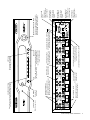
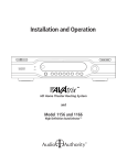
Panel Descriptions
Shown on the page opposite are the front and back views of the AVM-562. Below is a view of the 1105BK Infrared Remote
Control. Each AVM-562 includes one 1105BK; additional 1105BK Remotes may be purchased separately, or you may
download the IR codes from www.audioauthority.com.
Model 1105BK* IR Remote Control
This full featured remote control is useful in basic AVAtrix installations for switching source signals to the main
output, but it also can be used at any wallplate/receiver location to switch source signals to individual wallplate
outputs. IR receiver and emitter required.
* The 1105BK is different from the Model 1105 only in appearance. Both units share exactly the same IR command set.
800-322-8346
www.audioauthority.com
Numeric keys 1-6 used for instant
source input selection and navigation
IR-LOCK key for temporary source control restriction
UNLOCK key used to cancel all temporary
restrictions
VIEW-LOCK key for temporary source viewing privacy
MENU key used to access AVM-562 setup menu
DISPLAY
MENU
GROUP
GROUP key use to select a group of Wallplates
LOCK
DISPLAY key used to switch between Residential and Professional panel display mode
ALL
ZONE
LOCK key used in conjunction with VIEWLOCK, IR-LOCK, and UNLOCK keys
SOURCE
ALL key used to select all Wallplates
DIM / SCROLL
ZONE key used to select a single Wallplate
SCAN
SOURCE key used to select source
input to Wallplates (Double click for
main output control in Pro Mode)
ENTER
ENTER key used to make menu selections
DIM/SCROLL (up/down) used to dim AVM562 panel display and for navigation
SCAN keys used to browse
AVAtrix inputs or navigation
Alpha keys used for navigation
A
D
G
J
B
E
H
K
C
F
I
L
Model 1105BK IR Remote
8
Audio Authority AVAtrix User Manual
Audio Authority AVAtrix User Manual
9
Pr
Pb
Y
AUDIO
R
L
D
REMOTE
CAT 5
OUTPUTS
1
SOURCE INPUT 1
VIDEO
IR
A
DIGITAL
OPTICAL
OUT
POWER LED
When lit, power is on
B
AUDIO
R
L
D
2
SOURCE INPUT 2
VIDEO
A
DIGITAL
OPTICAL
OUT
IR
Pr
Pb
Y
B
AUDIO
R
L
D
3
SOURCE INPUT 3
VIDEO
A
DIGITAL
OPTICAL
OUT
IR
Pr
Pb
Y
B
AUDIO
R
L
D
4
SOURCE INPUT 4
VIDEO
CAT 5 OUTPUT
Connection for Cat 5
COMPONENT VIDEO INPUT
wallplate/receiver
YPbPr input port for position 1
ANALOG AUDIO INPUT
Pr
Pb
Y
Pr
Pb
Y
B
AUDIO
R
L
D
5
SOURCE INPUT 5
VIDEO
A
DIGITAL
OPTICAL
OUT
IR
Pr
Pb
Y
B
AUDIO
R
L
D
6
LOCAL ANALOG AUDIO OUTPUT JACKS
A
DIGITAL
OPTICAL
OUT
IR
Pr
VIDEO
B
Pb
Y
R
L
D
DIGITAL
OPTICAL
Made in USA
18V DC
POWER
MAIN IR
FLASH CARD
RS-232 CONTROL
Model AVX-562
High Definition Cat 5 Matrix
MAIN (LOCAL)
AUDIO
POWER JACK
Use only the included 18V power
supply
INFRARED OUT
Used only with
compatible IR products (see Page 16)
INFRARED IN
Control AVAtrix
behavior using
remote control
signals
RS-232 PORT
Control AVAtrix
behavior using
a serial control
system
FLASH CARD
PORT
Save and load
setup files or use to
upgrade firmware
NAVIGATION AND ENTER KNOB
Turn knob to navigate on-screen menus,
press knob to enter (press and hold knob
and touch MENU to enter setup mode)
LOCAL DIGITAL AUDIO OUTPUTS
All digital audio inputs are available
at the coaxial and optical outputs
SOURCE INPUT 6
VIDEO
IR ROUTER OUTPUT
Discrete IR signals from
zone to selected source
LOCAL COMPONENT VIDEO OUTPUT
Component video input signals
are available on YPbPr jacks
A
DIGITAL
OPTICAL
OUT
IR
IR ROUTER LED
Indicates IR traffic
MENU KEY
Switches between Residential
and Professional Modes, or
touch while pressing the knob
to enter the setup menu
SOFT KEY
Performs the task indicated
on the display (usually exit)
DIM
Press to dim the display
(four brightness levels)
DIGITAL AUDIO INPUT
Optical OR coaxial inputs for
position 1 (DO NOT connect both
inputs from the same source)
IR WINDOW
Receives IR
commands
SOURCE SELECTION
Press a key to switch the corresponding input to the
main output; these keys are also used for setup
Installation
You may wish to consult with a qualified custom electronics installer if you are inexperienced with UTP wiring and cable
termination. You should be familiar with Cat 5e/6 cable termination tools, techniques, testing, and wire routing principles.
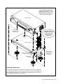
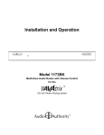
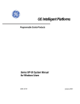
1. Assembling Expanders. Follow these steps if you are installing Models 1172BK, 1176BK or other expanders with
your AVM-562 or AVX-562. Otherwise, skip to Step 3.
All video, audio, and communication signals between sources, Cat 5 outputs, and audio system outputs travel through
the special ribbon bus cable. The AVAtrix normally ships with a 4-port bus cable, leaving two open ports for expanders. If you need to add more than two expanders, order AVM-562E or call Audio Authority Technical Support.
a. Lay the Model AVM-562 upside down on a protective surface, such as a terry cloth towel.
b. Remove the four feet and the bus access covers (save them and their attaching screws).
c. Gently feed the loose end of the bus cable out of the bus access opening.
d. Plug the next connector into the port visible through the expander case opening—apply enough pressure with fingers or
a plastic tool to assure that the plug is completely seated.
e. Turn the next product to be stacked upside down (e.g. Model
1172BK or 1176BK), thread the bus cable through its bus
access openings, and engage its four threaded studs with the
four threaded holes in the Model AVM-562 formerly occupied
by the feet.
f. Tighten the hex head screws in the bottom of the stacking
product in sequence a few turns each, until they are all snug.
g. Carefully plug the ribbon cable into the bus port. Continue
this stacking procedure until all units have been assembled.
View the bus through the bus port to be sure all plugs are fully
seated.
h. After plugging the last connector of the bus into the bottom
unit, carefully tuck any excess cable into the empty space
inside the last unit. Be certain the back of the connector does
not contact the metal case. To disconnect a bus plug, squeeze
the side latches.
i.
Install the bus port cover and feet you removed from Model
AVM-562 onto the bottom unit and turn the stack right side up.
Note: If you are installing expanders on Model
1156 or 1166 the address scheme is different.
Refer to the AVX-561 or AVX-661 manual.
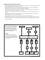
2. Addressing and Initial Testing.
a. Set the Address dial on each Model 1172BK
and/or 1176BK: set the upper-most Model
1176BK address to “B”, the next one to “C”,
and so on. The AVM-562 Cat 5 output row is
permanently addressed “A”. Follow 1172BK
manual for addressing 1172BK.
b. Temporarily plug in the power supplies of
all units to a plug strip so that you can turn
them all on at one time. The opening screen
on the Model AVM-562 display indicates that
the unit is powered and shows the number
of expanders that have been recognized.
If this number is different from the number
actually present, look for the bus not being
fully plugged into a unit or a unit incorrectly
addressed.
10
Audio Authority AVAtrix User Manual
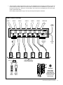
Zone “A4”
AVM-562
1176BK
1176BK
1
2
3
4
5
6
1
2
3
4
5
6
1
2
3
4
5
6
(A)
B
C
AVAtrix opening screen shows expanders recognized.
If you need to add more
than two expanders, order
AVM-562E or call Audio Authority Technical Support.
MODEL AVM-562
REMOVE FEET
AND INSTALL ON
LAST EXPANDER
The bus cable is
fragile! Do not crimp
or tug on the cable
as you install the
expanders.
THREADED
STUDS
1172BK or 1176BK
BUS
CABLE
BUS ACCESS
OPENING
REMOVE BUS
ACCESS COVER AND
INSTALL ON LAST
EXPANDER
BUS ACCESS
COVER
Stacking Components
This diagram shows the parts and locations for stacking components. The procedure
must be performed with the units upside down. Note: if more than two expanders are
to be installed with the AVAtrix, you must order Model AVM-562E which has a longer
bus cable with the capacity for five expanders.
Audio Authority AVAtrix User Manual
11
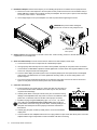
3. Rack Mount Adapters. Perform these steps if you are installing this product in a standard 19-inch equipment rack.
a. Remove the cover screws adjacent to the front panel of each product and use them to mount Model 1192 (for
Model AVM-562) or Model 1191 (for Model 1172/76) rack adapters. Be sure to place a spacer under the adapters at every screw location – see illustration.
b. Use a straight edge to line up rack adapters on a stack of product before tightening the screws.
!
CAUTION! This product will be damaged if
spacers are not used on every adapter screw.
IMPORTANT!
Do not mount adapters
without spacers
4. Setting in Place. Place the AVAtrix on its shelf or in the rack. If rack mounting, secure it to the rails with the screws
supplied with the rack adapter kits.
5. Audio and Video Hookup. Connect and test sources with the local video display in these steps.
a. Connect each source unit to its respective set of AVM-562 input jacks.
b. Use high quality cable and keep the runs under 6 feet if possible, especially for component video connections.
c. Connect either, but NOT BOTH optical and coaxial digital audio. Connect all the other signals available from the
source unit: component video and analog audio.
d. Connect a video display and audio system to the Local (Main) Output jacks. Use optical and/or coaxial digital
audio outputs. The AVAtrix does not convert digital audio to analog audio, so connect analog audio to TV’s
inputs if required.
e. Turn on the sources and AVAtrix temporarily for an initial test. Select each source to the local TV and sound
system to verify basic functions. Remove power and continue installation.
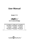
6. Cat 5 Zone Connections.
a. Pull two lengths of good quality Cat 5e or Cat 6 UTP cable from the main system to each receiver location. Shielded Cat 5 cable may be used, but offers
no performance advantage.
b. Carefully mark cables of each pair A and B; if they are connected incorrectly,
damage to the wallplate/receiver may result. It is best to use a different cable
jacket color, or label each end for A and B to ensure proper connection.
c. Install RJ-45 plugs using EIA-568B pairing (pins 1-2, 3-6, 4-5, 7-8). Check
each cable with a professional network cable tester before plugging it
into the AVAtrix, even when using pre-made cables. Continuity testing is not
adequate! The twisted pairs must be properly matched for balanced line
transmission.
!
Pair 3
Pair 2
Pair 1
Pair 4
Modular Jack (RJ-45)
1 2 3 4 5 6 7 8
W-O O W-GR BL W-BL GR W-BR BR
T568B Pair Assignments
d. Carefully plug the pairs of cables (A and B) into the correct A and B AVAtrix
output jacks.
e. Connect cables to each wallplate/receiver. Be sure to plug cable A into jack A and cable B into jack B. Leave the
wallplate Cable Length Compensation controls accessible until after zone testing.
12
Audio Authority AVAtrix User Manual
f. Adjust the Cable Length Compensation control on each wallplate/receiver according to the distance of that unit
from the head end. Set the dial to the nearest number of hundreds of feet of cable distance (e.g. 200 feet = 2).
During zone testing (see 7, below) it is recommended to use an HD source and display to fine tune each cable
length compensation setting.
Note: Setting compensation too high or low may result in picture dropouts or distortion.
Basic AVAtrix Wiring
SOURCE 1
SOURCE 2
SOURCE 3
SOURCE 4
SOURCE 5
SOURCE 6
MAIN OUTPUT
To IR
distribution
system
AVX-562
Address = A
Two runs of
Cat 5e/6 per
Wallplate
18V Power
Supply
System capacity shown:
6 Cat 5 wallplate/receivers
(each has selectable input)
IR Receiver
A
B
1105
Remote
Control
Universal
Remote
Control
!
Caution!
Do not apply
system power
until cables are
tested and A and B
connections have
been verified.
Audio Authority AVAtrix User Manual
13
7. Zone Testing. Plug the power supply furnished with the AVAtrix and each expander into its respective unit, and plug
the power supplies into a plug strip so that all units can be turned on at one time.
a. Power indicators on the AVAtrix, all expander units, and all installed wallplate/receivers should be on. If a
wallplate power light does not come on, unplug the Cat 5 cables immediately and re-test them.
b. The opening screen on the AVAtrix panel indicates how many expanders have been recognized. The screen
should match this illustration if a Model AVM-562 is installed with three 1176BK expanders for a total output of
24 Cat 5 outputs.
c. Apply power to all sources and video displays with associated equipment. Use the 1105BK remote control to verify
video and audio signal integrity of sources at each zone
location. Fine tune cable length compensation settings, then
permanently mount each wallplate.
Routing Control Options
Three different remote control methods may be used for matrix routing:
•
Native IR remote; Model 1105BK (Model 1105 IR codes are identical, but appearance is different).
•
Comprehensive IR controllers can learn or download the AVAtrix IR codes.
•
RS-232 commands. System controllers capable of RS-232 communication can be connected to the serial port on the
AVAtrix. To program such controllers, refer to Appendix D in this manual.
1. Using AVAtrix IR Commands in Other Remote Controls. Comprehensive IR controllers can learn or download the
AVAtrix IR codes along with the codes of the sources and can output a macro containing source controls and AVAtrix
selection controls.
a. If the 1105BK codes are available from your remote control company, download and/or activate those files.
b. A CCF file containing 1105BK codes can be downloaded from the Audio Authority website:
www.audioauthority.com/page/software.
c. As an alternative, follow the manufacturer’s instructions to teach a learning remote control the numeric 1
through 6 commands from the 1105BK remote. You may also wish to teach it View-lock, IR-lock, and Unlock.
2. Teaching Infrared Commands to the AVAtrix for Local Control. An additional method of controlling the AVAtrix
local (Main) output is to teach it commands from other brand remotes using the Learn IR Codes setup screen. This
feature does not apply to remote Cat 5 zones. For instructions on the learning feature, call Audio Authority Technical
Support at 800-322-8346.
Installing Infrared Equipment
1. Tips for Using Infrared Control.
a. If you are using standard hand-held remote controls, ensure correct operation by avoiding sources of light pollution such as Plasma and LCD TVs, direct sunlight, fluorescent light, etc. Experiment with the physical placement of the IR receiver to avoid interference.
b. If a source of interference cannot be eliminated or avoided, use IR receivers that block that type of interference,
such as Plasma-proof or LCD-proof receivers.
c. Use the IR diagnostic tools to troubleshoot IR problems (See Appendix C).
!
NOTE: Due to variances in IR commands, carrier frequencies, and error tolerances between manufacturers,
some sources may not be able to be controlled through the AVAtrix internal IR routing system.
d. If you are using a comprehensive IR control system, provide a stick-on emitter or blaster from the infrared
system to communicate throught the AVAtrix front panel optical IR receiver. You can also patch the IR signal
directly to the IR input port on the rear panel using a properly fabricated 3.5mm cable (see page 7). Call Audio
Authority for more information.
14
Audio Authority AVAtrix User Manual
Infrared Control Wiring
Passive
IR Emitter
Source 1
A single emitter or blaster may be
connected to the Main IR output
jack, or use the individual IR output
jacks at each source connection
for discrete source control.
Source 2
Source 1
Source 2
Source 3
Source 3
Individual Source
Output Jacks
(IR Router)
Main IR Output Jack
(3rd party IR from all zones)
Do not use a
powered connection
block or signal
amplifier with the
AVAtrix.
AVM-562
AVX-562
Receiver Pinout
Receivers are powered by
12 volts on the sleeve
contact of the Cat 5
wallplate/receiver IR jack.
9879 Cat 5
receiver
Connect IR receiver directly
to the wallplate/receiver - DO
NOT use a connecting block.
IR receiver
(12 volt, 3-wire
receivers only)
Remote Control
Two-wire
IR blaster
or emitter
Tip = Signal
Ring = Ground
Sleeve = +12 Volts
Warning: Connect
receivers directly to
wallplate/receiver,
(12V, 3-wire only)
without a powered
connecting block.
Emitter Pinout
A passive emitter usually
has a two-conductor plug.
Tip = Signal
Sleeve = Ground
Warning: Use only
non-powered emitters,
without connecting block.
Using Compatible Infrared Emitters and Receivers
The AVAtrix has an active, 12 volt IR pathway that allows it to power the IR receivers at the zones, and drive emitters connected to the AVAtrix. Do not use powered IR systems that are designed to use a separate power source, or
equipment damage could result. The AVAtrix powers IR receivers with 12 volts; do not use IR receivers designed for
any other voltage. Use only three-wire receivers or damage could result.
Audio Authority AVAtrix User Manual
15
2. Setting Up IR at the Remote Zones.
a. Plug an Infrared Receiver into the 3.5mm jack on each wallplate/receiver that is to have IR source selection
capability. (Use only compatible receivers without external power supply–see page 15 for more information.)
b. Infrared commands returned from a zone to the AVAtrix can immediately select the source to be played on that
wallplate/receiver output. Use the IR routing connections, or the main IR output from the AVAtrix (see 3 below).
c. IR commands for the AVAtrix (1105 commands) are returned through the Cat 5 cables and stop at the AVAtrix.
Other IR commands are repeated on the AVAtrix IR output jacks.
3. IR Routing vs Main IR Output. If all sources have different code sets, one IR blaster connected to the AVAtrix Main
IR Output can be used to control all the sources in an equipment rack. If there are several sources that share identical
IR codes, such as satellite receivers, individual IR emitters should be used for each source.
a. IR Routing: To route IR commands discretely from an individual zone to the selected source only, connect IR
emitters from the individual IR Out jacks at each AVAtrix source position to their respective source IR input
jacks, or use a stick-on emitter. Other sources sharing the same IR code set are not affected.
b. Main IR Output: Non-AVAtrix IR commands returned from all matrixed Cat 5 zones are repeated through the
Main IR Output jack on the AVAtrix. This output can be used to feed commands from the zones to an external
IR control system, or simply to an IR blaster. Do not use IR connecting blocks (see “Using Compatible Infrared
Products” on page 16).
c. Model 1170BK IR capabilities: The AVAtrix cannot be directly controlled using the Cat 5 IR pathways from Model
1170BK. Model 1105BK IR commands returned from wallplate/receivers connected to Model 1170BK Cat 5
ports are repeated through the Main AVAVtrix IR Output jack, but they perform no function within the AVAtrix.
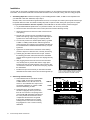
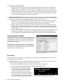
Customizing the AVAtrix
Apply custom source names, create zone groups, apply permanent
source restrictions, and lock out certian front panel controls. Refer
to the Setup Menu Chart on the next page for a complete list of
custom options. It is recommended to save your custom setup to
the flash card as a backup.
The easiest way to configure the system is to use the AVAtrix PC
Setup Utility (shown at the right); however, any configuration may
be performed via the front panel controls and/or remote control. To
use the PC Utility, see pages 17 and 21.
The AVAtrix PC Setup Utility is compatible with Windows 98,
98SE, ME, XP, Vista, Windows 7.
Direct Setup
Setup via the front panel controls/IR remote is guided by on-screen prompts, so only highlights will be covered here. See
the next page for a Setup Menu Map.
1. General user tips. Use the knob to navigate to each setup option, press the knob to select it, then follow on screen
instructions. The IR remote may be more convenient for many setup tasks.
a. Setup Menu: Press MENU on the remote, or press and hold the knob and touch MENU.
b. Some of the operations are password protected. The password is always “2-3-6”.
c. The knob can be a multi-directional navigation
tool on certain screens. Arrows in the upper right
corner indicate the current direction on these
screens. To change directions, push the knob.
d. Some screens offer editing tools such as change
case, insert, delete, etc. The Case tool allows upper and lower case letters, numbers, or symbols.
Note: using all upper case yields the best results.
16
Audio Authority AVAtrix User Manual
The text edit tools are indicated along the bottom of the screen: Case,
Skip Back, Skip Forward, Overstrike/Insert, and Delete.
e. The wallplate/receiver zone outputs are numbered 1- 6 on each output level, the first level being the AVM-562
outputs. The AVM-562 outputs are always addressed “A” and the next level, Model 1176BK, should be “B” and
so on. An individual zone output is referred to as A2, or B5, etc. (See page 10.)
2. Custom Setup Highlights
a. Settings. These options are convenient if the AVAtrix will be located in a visible area or around children. Lock
certain front panel controls or allow the display to turn off during times of inactivity.
b. Name the Sources. Especially for installations where the AVAtrix is used as a stand-alone whole house entertainment network, custom source names greatly enhance the usability of AV equipment within sight of the
AVAtrix screen. Choose from a list of default names or enter custom names. These names appear prominently
on the AVAtrix screen.
c. Learn IR Commands. The AVAtrix can learn 3rd
party IR commands. See the previous section on
IR.
d. Name the Groups. Enter names for output groups.
Group View (from Professional Mode) displays a
list of up to six named groups to the user and indicates which source is currently assigned to each
group (see Operation). This view makes it easy to
monitor and manage the content being shown on
video displays in different rooms or areas from a
central location. The number of groups is limited to
six. Groups can contain any number or combination of zones, including the local zone.
e. Assign Outputs to Groups. The groups you
named are listed across the bottom of the screen.
Navigate to the Zone address and touch the key
for group names/numbers to which it should belong.
f. Assign Restrictions. These controls allow the system administrator to prevent a zone from viewing a
source. This operation is password protected (2-36). Highlight a source (e.g. GAME, DVD, etc.) and
use the four buttons labeled at the bottom of the
screen to set restrictions for that source. In some
cases, it may be convenient to restrict all and then
allow particular zones. These restrictions may also
be configured via the PC Utility (page 21).
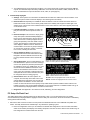
1
2
3
4
5
6
Group Name
Group Number
Group view offers control of zone groups by name, and can be
used in six-zone systems to name the zones.
A.ALL = Allow all zones to view this source
R.ALL = Restrict all zones from this source
ALLOW = Allow the highlighted zone to view this source
RESTR = Disallow the highlighted zone to view the source
g. Save/Load File. When all custom options are
complete, save the setup to the flash card in case
system settings are changed or lost. The card can
be kept either in the AVAtrix or in some other safe
location. A card could also be used to quickly set up similar AVAtrix systems installed in other locations. The
Installer can keep a copy of each AVAtrix installation on one card for reference. To initialize a blank card, go to
www.audioauthority.com/page/software, and follow the instructions.
h. Diagnostics. See Appendix C for instructions on IR, addressing, and other diagnostics.
PC Setup Via Flash Card
The AVAtrix Setup Utility is already loaded onto the flash memory card, or you can download it from our website:
www.audioauthority.com/page/software. Highlights of the PC Utility are covered here, but more information is available by
clicking HELP inside the Utility.
1. Remove the flash card from the slot in the rear panel of the AVM-562 and insert it in an MMC/SD compatible card
reader. The Utility should launch automatically in any Windows™ operating system.
a. Name of Configuration. Enter up to 32 characters to describe this configuration. This is the “label” that will be
visible on the AVAtrix panel display when loading setup files. This name is not the same as the “filename.cfg” for
this configuration as it will be saved onto the card.
Audio Authority AVAtrix User Manual
17
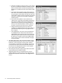
b. Restriction Feedback for View-lock. When a user restricts
the source, and restriction feedback is enabled, the video
blinks to indicate that the command was implemented. If
feedback is not enabled, the feature works without visible
effect.
c. Enter Custom Source Names. These names are the “labels” shown on the AVAtrix panel display representing the
six input positions. Short names may have up to four characters (letters, numbers, spaces or symbols). Long names
may have 13 characters, and are visible in Residential
and Group views.
d. Enter Custom Group Names. These names are the
“labels” shown on the AVAtrix panel display representing
each of the six available output zone groups (groups of
wallplate/receiver locations). Short group Names may
have up to four characters (letters, numbers, spaces or
symbols). Long names may have up to 13 characters.
e. Assign Zone Groups. Each group may contain any
combination of wallplate/receivers from matrix routers, as
well as the main output. Any zone may appear in more
than one group.
f. Source Restrictions. Any source may be restricted from
any wallplate/receiver. Under Zones, select the Cat 5
output address. Then check any sources you wish to prohibit at this location. Select the next zone and proceed in
the same way. To restrict a source from the Main output,
simply check the Source number under Main. See page
21 for more details.
2. The AVAtrix flash memory cards are issued with blank configuration files already saved onto the card, so you may overwrite
these files, or save your file with a new file name; however,
you must retain a .cfg extension on the filename. You may use
a new blank card, but the card must be formatted FAT32, and
have at least one configuration file saved to it by this application in order to function with the AVAtrix.
3. After saving the setup file (.cfg file), plug the flash card containing the setup file into the AVAtrix card slot.
4. Temporarily apply power, go to the SETUP menu, choose
SAVE/LOAD FILE, choose the desired setup configuration file
and follow the instructions on the screen. The 3-digit password
is 2-3-6.
18
Audio Authority AVAtrix User Manual
Setup Menu Chart
• To access the menu, press MENU on the IR
remote; or press and hold the knob, and touch
the front panel MENU key.
• To perform password protected operations,
enter “2-3-6” and ENTER on the front panel.
Settings
Lockout Front Panel Keys
Lockout all front panel keys except for Display and the key sequence for Setup
Menu access.
Lockout Front Panel IR
Detector
Detection ignores any IR commands visible from the front panel IR window; IR
input jack on rear is still active.
Enable Display Blanking
Allows the front panel display to turn off after a period of inactivity.
Enable Feedback for Private
Viewing
When enabled, this feature causes a brief break in the video signal as an
indication that an “IR lock” or “view lock” signal has been implemented.
Name the Sources
Assign custom short names and custom long names to each source.
Learn IR Commands
Teach the AVM-562 to respond to 3rd party IR commands.
Name Groups
Assign custom short names and custom long names to each group of zones.
Assign Outputs to Groups
Divide the array of Cat 5 receiver outputs into geographic or functional zone
”groups”.
Assign Restrictions
Restrict source signals from particular zone wallplate/receivers
Save/Load File
Save Current Setup to Flash
Card
Save the current setup configuration to memory card in rear slot. Does not
overwrite any existing setup files.
Load New Setup from Flash
Card
Scan and choose firmware upgrades from card or import setup data saved from
an AVAtrix or saved from the AVAtrix PC application.
Load Demonstration Setup
Loads example setup including custom short and long source names and 24
simulated remote Wallplate locations.
Load Default Setup
Clears user setup and loads factory default setup.
Upgrade Operating System
Choose from available operating system firmware files on the flash memory
card to install a firmware upgrade.
Contact Installer
Enter contact information. Up to four lines, 42 characters per line.
Diagnostics
Expander Address
Shows letter address of all detected expanders, including the six native AVM562 Cat 5 matrix outputs.
Local IR
Shows on/off times of IR signals received through the front panel.
Zone IR
Shows on/off times and carrier of IR signals received through the Cat 5
wallplate/receivers.
Firmware Version
Shows the firmware version loaded on each component of the AVAtrix system,
and the firmware upgrades available on a flash card loaded in the card slot.
Source and Control
Restrictions
Shows the parental restrictions on sources to wallplate/receivers and local
output.
Audio Authority AVAtrix User Manual
19
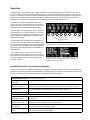
Operation
The AVAtrix allows you to select the source being played at each Cat 5 wallplate/receiver zone from the head end, and
if the zone location is equipped with an infrared receiver, the source can be selected using an infrared remote control at
the zone. Two operation screens are available: Residential and Professional. Use Professional mode to control the zones
from the head end. Use Residential mode if the AVAtrix is visible at the local zone. To switch between Residential and
Professional, press the front panel MENU key, or the DISPLAY key on the 1105BK remote control.
In Residential mode, the normal screen displays the
custom long name of the selected source, the six short
names of the sources, which of these sources is currently
selected to the Main Output (highlighted short name).
The Professional screen displays the source currently assigned to each zone or group and allows you to choose a
new source for each zone or group. A special group view
is also available for a detailed overview of the sources
assigned to each group.
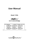
In Professional mode, the ZONE screen displays the array of remote outputs. Along the bottom, it displays the six
short names of the sources and which of these sources is
currently selected to the MAIN (local) output (highlighted
short name). To the right it displays the virtual MAIN, ALL
and GRP modes.
In Group View (shown) it is simple to show the current
source selected for each group. If some TVs in a group
have a different source selected (e.g. Living room above)
the AVAtrix places an asterisk by the source name displayed for that group.
1
2
3
4
5
Source Name
6
MENU
Source Number
Selecting a source in Professional Mode. Currently Source 2, which is
Satellite Receiver #2, is selected on Cat 5 receiver (zone) A5.
Professional mode in Group view. The TVs in the livingroom do not
all display the same source, as indicated by the * (This view is not
available if no groups are assigned.)
Head End Operation: Key Sequence Examples
The key sequences for several different operations using front panel controls or IR remote control are shown below. All examples assume the starting point is Professional Mode. To navigate using the front panel controls rotate the knob to move
the cursor, press the knob to change directions when appropriate (up/down vs. left/right).
1105BK Remote Control (From Professional Screen)
Changing the source on the Double-click SOURCE; Press the desired number key or press the Left/Right SCAN keys.
local output
Changing the source on a
ZONE (Cat 5 receiver)
Use the up/down/left/right keys or Alpha key/Number key to highlight the zone; press the
SOURCE key; press the Number key for the desired source. (e.g. Zone A1, Source 4.)
Changing the source for a
group of zones
Press GROUP (if necessary); use the up/down keys to highlight the desired zone group;
touch the Number key for the desired source. (e.g. Group 1, Source 2).
One source for all zones
Press ALL; press the Number key for the desired source. (Press ENTER to UNDO.)
AVAtrix Front Panel Controls (From Professional Screen)
Changing the source on the Touch soft key until MAIN is highlighted; touch the desired source input selection key or
local (MAIN) output
turn the knob.
20
Changing the source on a
ZONE (Cat 5 receiver)
Turn the knob to navigate, press the knob to change directions; when the desired zone is
highlighted, touch the desired source input selection key.
Changing the source for a
group of zones
Touch soft key until GRP is highlighted; turn the knob to select the desired group; touch a
source input selection key to assign a source.
Changing the source for all
zones
Touch soft key until ALL is highlighted; touch the desired source input selection key to assign a source. (Press the knob to UNDO.)
Audio Authority AVAtrix User Manual
Remote Zone Operation: Key Sequence Examples
The key sequences for several operations using the 1105BK IR remote control from the Cat 5 wallplate/receiver zone are
shown below. The zone must be equipped with a compatible IR receiver.
Changing the source on the
zone output
Press the desired source number key.
Activate VIEW-LOCK
Press LOCK, then press VIEW-LOCK. No other zones can select the source selected
at this zone, and zones viewing this source are locked out.
Activate IR-LOCK
Press LOCK, then press IR-LOCK. No other zones can change settings (channels, etc)
through the AVAtrix IR pathway.
Clear all LOCK commands
Press LOCK, then UNLOCK.
About Restrictions
Three types of restrictions are available: View-lock, IR-lock, and permanent source/zone lock. View-lock and
IR-lock are performed using the IR control from a particular zone. When the viewer wants to prohibit others from
controlling the source, (changing the channel, etc) or prevent viewing the source at all, he or she can activate one
800-322-8346
of the temporary restrictions. View-lock and IR-lock expire after 300
minutes.
www.audioauthority.com
If a user at a zone Viewlocks his source, other
viewers watching the same
source see a blank screen
until they choose a different,
available source. If a user
tries to select a restricted
source, the AVAtrix does not
respond.
UNLOCK key used to cancel all temporary restrictions
IR-LOCK key used for
source control restriction
VIEW-LOCK key used for
private viewing restriction
DISPLAY
MENU
Model 1105BK
Remote Control
GROUP
LOCK
LOCK key used in conjunction with VIEW-LOCK, IRLOCK, and UNLOCK keys
ALL
As a default, the AVAtrix
ZONE
SOURCE
causes a “blink” in the video
DIM / SCROLL
to confirm that a View-lock or IR-lock command has been received. This feedback can be deactivated using the
front panel setup menu or the PC setup utility (see page 18).
To permanently prohibit certain zone(s) from viewing a source,
use theENTER
AVAtrix setup menu or the PC setup utility
SCAN
to restrict the zone(s) from viewing the source. Using front panel controls, this operation is password protected (23-6). The front panel controls offer some advantages such as a single command to restrict all zones from a source.
See page 17 for details.
Note: all restrictions can be temporarily suspended using Diagnostic Modes (Appendix C).
Setting Restrictions with the PC Utility
Under the “Zones” heading there are two columns separated by hyphens. The left column is
the zone address* and the right column numbers
these addresses from 1-36 for reference.
•
Select the desired zone address under the
“Zones” heading.
•
Click the box next to the source(s) to be prohibited in the selected zone.
•
To prohibit a source from the main (local)
output, click the source number under MAIN.
A
D
G
J
B
E
H
K
C
F
I
L
Model 1105BK IR Remote
*See Page 10 for an explanation of zone numbers
and letters.
Audio Authority AVAtrix User Manual
21
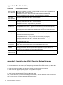
Appendix A: Troubleshooting
Symptom
Causes and Solutions
Flashing POWER
LED on Expander
• Improperly terminated Cat 5 cables – Use professional cable tester and re-apply cable ends
• Bad power supply – Install new supply
• Damaged Cat 5 receiver – Disonnect all Cat 5 cables and observe POWER LED
• Bent pins on internal bus cable connector – Call Audio Authority for assistance
No video or IR
control after
adding expanders
• Incompatible firmware versions – Upgrade to latest firmware (see www.audioauthority.com)
• Improperly seated internal bus cable – Check connection
No video or audio
• Improperly terminated Cat 5 cables – Use professional cable tester and re-apply cable ends
• Improperly seated internal bus cable – Check connections
• Damaged Cat 5 port on AVAtrix – Try Cat 5 cables on a different port
• Damaged Cat 5 receiver – swap with known good receiver
1176BK or 1172BK • Improperly seated internal bus cable – Check connections
Expanders not
• Incompatible firmware versions – Upgrade to latest firmware (see www.audioauthority.com)
recognized
• Incorrect address setting – Set correct expander address (see page 8 or see 1172BK manual)
• Damaged Address Dial – Use Expander Diagnostic (see Appendix C) to check settings and
functionality
IR does not
function properly
• IR interference such as LCD/Plasma screen, fluorescent lights, space heater, sunlight
• Eliminate sources of IR interference and use Plasma-proof and/or LCD-proof IR receivers
• Experiment with relocating the IR receiver
• Check for IR interference using the IR diagnostics
• Incompatible IR receivers – use only 12 volt, three-wire receivers (see page 14)
• Improperly terminated Cat 5 cables – Use professional cable tester and re-apply cable ends
• Improperly seated internal bus cable – Check bus cable connections
Note: 1105 and 1105BK IR commands sent from wallplate/receiver IR ports are not passed to any
of the AVAtrix IR Output jacks.
Does not respond
to a learned IR
command
• Wrong IR code learned or IR remote cannot be learned
• Note: AVAtrix “learned commands” do not work with wallplate/receiver zones
Does not respond
to RS-232
• AVAtrix commands not stored in remote control system – See Appendix D
• Wrong type of RS-232 cable – See specifications in Appendix D for proper cable pin-out
• Incorrect settings in software – See specifications in Appendix D
Does not repeat
commands from a
certain IR remote
• Some IR remotes cannot be processed by the AVAtrix
• IR output not properly connected to external IR system – call Audio Authority Technical Support
Appendix B: Upgrading the AVAtrix Operating System Firmware
The latest version is available to download to your PC from www.audioauthority.com/page/software.
1. Place the AVAtrix flash card containing the latest operating system data into the AVAtrix card slot. (The SD or MMC
card must be formatted FAT32.)
2. Press the knob and touch MENU. The setup menu appears. Scroll and choose “Save/Load File”.
3. Scroll and choose “Upgrade Operating System.” The upgrade screen appears.
4. Touch, in order, 2-3-6 then “Load” (or 1).
5. Scroll and select the latest operating system (e.g. May 27th, 2008).
After you select the version you want the screen displays “Downloading...” This step takes from one to several minutes.
After the screen displays “Completed” the AVAtrix reboots several times.
22
Audio Authority AVAtrix User Manual
Appendix C: How to Use Diagnostic Modes
To access diagnostic modes, enter Setup Menu (press the knob and touch MENU) and select DIAGNOSTICS at
the bottom of the menu.
Expander Address Diagnostic
This diagnostic can be used to determine whether all of your AVAtrix expanders are set to the correct address.
Enter this diagnostic mode and then turn the address dial on the rear of each expander until the “X” on the screen
is under the correct address. The AVM-562 has an 1176 inside the chassis that is addressed “A”. If A does not appear on the diagnostic screen, the internal bus cable may be loose. The Model 1170 does not have an address or
address dial.
Firmware Version Diagnostic
This diagnostic shows what firmware version resides in each expander in the AVAtrix network, as well as what firmware upgrade versions may be stored on the flash card in the AVAtrix card slot. This informaiton helps to determine
if the AVAtrix needs a firmware upgrade or if all processors in the system have been successfully upgraded.
Local IR Diagnostic
This diagnostic shows the raw on/off times of the encoded IR signals coming from any remote (other than the 1105)
pointed at the front panel IR window of the AVAtrix. This diagnostic shows the “bit times” only and does not show carrier
frequency information. The first command in the test may result in zeros, so press the button twice to get a useful
readout.
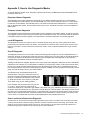
Zone IR Diagnostic
This diagnostic shows the raw on/off times of the encoded IR signals coming from any Cat 5 wallplate/receiver. It
shows the “bit times” as well as the period of the IR carrier. Dividing one (1) by the number of microseconds shown
on the screen results in the detected carrier frequency (see example below). This diagnostic is very helpful for
troubleshooting IR response issues in an AVAtrix system.
“Waiting for I/R data from wallplate” appears on the entry screen of this diagnostic. Watch this screen to indicate IR
interference from a Plasma TV or other ambient conditions. Do not press any buttons on IR remote controls during
the test. If any other message appears during the test, IR interference is present. Go to a wallplate/receiver location and press a button on a source unit IR remote (not the the 1105BK). The first command in the test may result in
zeros, so press the button twice to get a useful readout.
The AVAtrix screen shows details similar to the
example above. The top line shows the zone from
which the command originated and the period of the
IR carrier. To determine the detected carrier frequency, divide the number on the screen by 1,000,000.
Then divide one (1) by the resulting number.
In this example, the command came from port two
on 1176 “A”. The period of the carrier is 26 microseconds. Divide 26 by 1,000,000 to get .000026. Then divide one (1) by .000026 to get a carrier frequency of
38.461kHz. Each decimal number is a “burst pair” in the IR data train. The first signal in this remote command turns
the carrier on for 3.460 milliseconds and off for 1.740 milliseconds. The second command was on for 400 microseconds and off for 460 microseconds. Use this information to see what data the remote is sending out and if it looks
correct. Zeros, or numbers that don’t show any perceptible pattern may indicate interference.
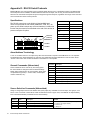
Source and Control Restrictions Diagnostic
All restrictions can be monitored and temporarily suspended from this screen. The initial screen shows the sources that
currently have permanent restrictions (R) and View-lock or IR-lock restrictions with time remaining. Touch PAGE to see
details on each source’s restriction status at each zone. Touch ALLOW ALL to temporarily suspend all restrictions for
troubleshooting purposes. Restrictions are restored upon exit of this diagnostic.
Audio Authority AVAtrix User Manual
23
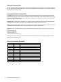
Appendix D: RS-232 Serial Protocols
Model AVM-562, and 1176 expanders can be controlled via RS-232 from a PC or dedicated controller. Two different RS232 serial protocols are available; the Abbreviated Command Set is simple, and one-way, and the Extended Command
Set has more commands and reports all system changes through the serial port, regardless of the origin of the command.
Use commands from either or both protocols.
Specifications
The RS-232 control port on the AVAtrix is fixed at 9600 baud.
There is no provision for flow control (XON/XOFF, DTR, etc.). On
power up, the AVAtrix echoes any received character, but that echo
function may be turned off as described at the end of this section to
prevent corruption of replies.
Row letter
(address)
Column
Zone “A4”
1
2
3
4
5
6
1
2
3
4
5
6
1
2
3
4
5
6
(A)
AVM-562 Row
B
1176 Row
C
1176 Row
Transfer Rate
9600 bps
Data Bits
8
Stop Bits
1
Parity
None
Flow Control or Data
Flow
None
Character type
ASCII
Interface connector
DB-9
Electrical rating
Pins 2 and 3, ±15 VDC
Pin-out
Pin 2, Tx
Pin 3, Rx
Pin 5, Ground
Shell, Ground
Null modem cable
Call Audio Authority
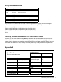
About Address Terminology
A “row” or row letter refers to a six-output array, either the internal Cat 5 outputs on the AVM-562 or an 1176 expander.
The AVM-562 row is always addressed “A” and other 1176 expanders should be addressed in order as shown above.
“Column” refers to the zone number as labeled on the AVAtrix or 1176 expander.
General Commands (Abbreviated)
These commands can be used at any time during operation of the AVAtrix to change the state of selected settings.
NOTE: Alpha characters are not case-sensitive. ASCII codes
not specified are ignored (i.e. control codes, unused alphanumeric characters, etc.).
Command
Description
P
Select Professional screen
R
Select Residential screen
V-
Unlock front panel controls
V+
Lock front panel controls
W-
Unlock front panel optical IR receiver
W+
Lockout front panel optical IR receiver
Y-
Disable display blanking
Y+
Enable display blanking
Source Selection Commands (Abbreviated)
Assign or change input sources to the AVAtrix main (local) output, any individual Cat 5 zone output, zone groups, or all
zones. In the “Command” column below, actual commands are shown in upper case, and variables are represented by
lower case bold characters (commands are not case-sensitive).
24
Command
Name
Description
Zwxy
Select Zone
Assign Source y to an individual zone wx
Gzy
Select Group
Assign Source y to all zones in a group z
Xy
Select All
Assign Source y to all zones
My
Select Main
Assign Source y to the AVAtrix local (main) output
Audio Authority AVAtrix User Manual
Variables
w = Row A-L (AVM-562 Cat 5 array or 1176)
x = Column 1-6 (output number)
y = Source 1-6
g = Group 1-6
Abbreviated Command Examples
The general format of commands is as follows:
Definition of output(s) to be acted upon (Zone, Group, Main, All
Address letter of output (row), when selecting Cat 5 output
Cat 5 output port number (column), when selecting Cat 5 outputs
Source number to be routed to the output(s)
ZC23
Example 1. To route source input 3 to the main AVAtrix output, send the following command:
M3
(The AVAtrix selects source 3 to its main output)
Example 2. To change the source assigned to an individual zone, enter “Z” followed by the letter of the row, followed by
the number of the column (zone number) from 1 to 6, followed by the number of the source input from 1 to 6. To assign
source input 5 to the 2nd Cat 5 zone on the “C” row (second 1176 expander), send the code:
ZC25
(Source 5 is selected to zone C2)
Example 3. To assign the same input source to all the zones, send the following command:
X4
(All Cat 5 zones output source 4)
Example 4. To change the source to an entire zone group, enter “Z” followed by the group number, followed by the desired source input number. To assign source 3 to group 2, enter the code:
G23
(All zones in group 2 play Source 3)
NOTE: If zone groups have not been assigned, no action results from this command.
Query Commands and Responses
Retrieve the status of any part of the AVAtrix system using the query commands. A query command sent by the controller
will elicit a response according to the following table.
Command
Name
Response
?P or ?R
Screen Mode
P if display is in professional screen
R if display is in residential screen
S if display is in any other screen (e.g. Setup)
?V
Panel Controls
– if panel controls are unlocked
+ if panel controls are locked
?W
Panel IR Receiver
– if IR receiver is unlocked
+ if IR receiver is locked out
?M
Main Output
Number of selected source
?Zwx
Cat 5 Output
Number of source selected by wallplate/receiver wx
Variables
w = Row A-L (AVM-562 Cat 5 array or 1176)
x = Column 1-6 (output number)
Audio Authority AVAtrix User Manual
25
Extended Command Set
All valid commands receive a response, and all changes in the AVAtrix system are reported. In the “Command” column on
the next page, actual commands are shown in upper case, and variables are represented by lower case bold characters
(commands are not case-sensitive).
Command Definitions (Extended)
Command: String received by the AVAtrix from the controlling hardware. Commands are not case sensitive and should
be 8-bit with No parity. The only characters recognized are: letters (a-z and A-Z), numbers (0-9), brackets ([ and ]), signs
(+ and -), and the question mark (?) . All other characters, including spaces and commas, are optional and may be either
included for clarity or omitted entirely.
Response: String transmitted by the AVAtrix to the controlling hardware. Responses are 8-bit with no parity. Responses
are transmitted as noted below, and always have a C/R L/F sequence (0x0d, 0x0a) after each line.
Query: A special command that requests the current status of one or more connections or settings, but does not change
any operation within the AVAtrix. A query must always contain the ? question mark character.
Parameters: Values contained within commands and responses which identify groups, sources, zones, and router devices.
j: group in range {1-6}
m: source in range {1-6}
n: zone in range {1-6}
x: A/V router device in range {A-L}
In this document, braces { and } are used to signify ONE of the enclosed characters. For example, {L,U} would mean
either of the two characters L or U .
General Commands (Extended)
26
Command:
Response:
Description:
[C,M,Im]
(M,Im)
Connect main output to source m
[C,Rx,On,Im]
(Rx,On,Im)
Connect zone n of A/V router x to source m
[C,X,Im]
(X,Im)
Connect all zones on all A/V routers to source m
[C,Gj,Im]
(Gj,Im)
Connect all outputs in group j to source m
[L,P]
(P,L)
Lock out front panel controls
[U,P]
(P,U)
Unlock front panel controls
[L,I]
(I,L)
Lock out internal I/R receiver
[U,I]
(I,U)
Unlock internal I/R receiver
[+,B]
(B,+)
Turn on display blanking after 45 seconds of inactivity
[-,B]
(B,-)
Turn off display blanking
[+,P]
(P,+)
Select Professional Screen
[-,P]
(P,-)
Select Residential Screen
Audio Authority AVAtrix User Manual
Query Commands (Extended)
Query:
Response:
Description:
[?,C,Rx,On]
(Rx,On,Im)
Query unit connection
[?,C,M]
(M,Im)
Query main connection
[?,C,X]
see below
Query all connections
[?,{L,U},P]
(P,{L,U})
Query status of panel lockout
[?,{L,U},I]
(I,{L,U})
Query status of internal I/R lockout
[?,{L,U},A]
(A,{L,U})
Query status of AutoSelect lockout
[?,{+,-},B]
(B,{+,-})
Query status of Display blanking
[?,{+,-},P]
(P,{+,-})
Query status of Display Screen
[?,{+,-},A]
(A,{+,-})
Query status of AutoSelect function
Any command not in the Exended Command Set which begins with a left bracket [ and ends with a right
bracket ] is an invalid command and the AVAtrix responds with the string (ERROR).
Response to [?,C,X] :
(RA,O1,Im)(RA,O2,Im)(RA,O3,Im)(RA,O4,Im)(RA,O5,Im)(RA,O6,Im)
(RB,O1,Im)(RB,O2,Im)(RB,O3,Im)(RB,O4,Im)(RB,O5,Im)(RB,O6,Im)
… through all devices …
(M,Im)
Power Up, Extended Commands and Their Effect on Echo Function
On power up, the AVAtrix sends the string (RESET). The AVAtrix also echoes any data received on the RS232 port. If any valid normal command is received (beginning and ending with brackets [ and ] ), the AVAtrix
ceases echoing characters to prevent these echoed characters from corrupting responses. The echo function
remains off until the AVAtrix is reset, either by interrupting power or by double-pressing the front panel knob.
Appendix E
Audio Parameters
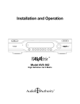
Specifications
Subject to change without notice.
Video Parameters
Format
Digital/Analog
Digital Input/Output Type
Optical+Coaxial In/Out
Input Impedance
75 ohms/50K ohms
75 ohms/10K ohms
Signal Type
Component YPbPr
Min Load Impedance
Video Formats
480i/p, 576i/p, 720p,
1080i/p
Multi-channel Digital
Yes
Frequency Response
10-50KHz
Input/Output Impedance
75 ohms
S/N Ratio
72dB
Input Ground Isolation
No
THD+Noise
0.03%
Gain
1
Crosstalk
75dB
Gain Accuracy
2%
Power
3dB Bandwidth
100MHz
DC Input Connector
5.5 X 2.1mm
Input Coupling
AC
DC Input/Polarity
18V/Center positive
S/N Ratio
61dB
Power Supply
571-023
Max Gain/Equalization
1
AVM-562 Heat Output
62 BTU/hr
Audio Authority AVAtrix User Manual
27
2048 Mercer Road, Lexington, Kentucky 40511-1071 USA
Phone: 859-233-4599 • Fax: 859-233-4510
Customer Toll-Free USA & Canada: 800-322-8346
www.audioauthority.com • [email protected]
v 1.0
752-495
4/09