1
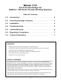
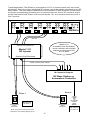
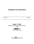
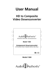
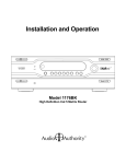
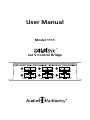
User Manual
Model 1111
5
A
3
B
A
A
B
A
B
A
B
A
B
B
2
A
B
A
B
3
IR
6
A
B
4
5
IR
A
Cat 5 Control Bridge
6
IR
1
B
1
IR
4
IR
A
B
2
IR
A
B
Model 1111
Cat 5 Control Bridge for
AVAtrix™ HD Home Theater Routing Systems
Table Of Contents
1.0
Introduction . . . . . . . . . . . . . . . . . . . . . . . 3
2.0
Checking Package Contents . . . . . . . . . . . . . . 3
3.0
Installation . . . . . . . . . . . . . . . . . . . . . . . . 5
4.0
Troubleshooting . . . . . . . . . . . . . . . . . . . . . 5
5.0
Limited Warranty . . . . . . . . . . . . . . . . . . . . 6
6.0
Regulatory Compliance . . . . . . . . . . . . . . . . . 7
7.0
Contact Information . . . . . . . . . . . . . . . . . . . 7
WARNINGS
•
Read these instructions before installing or using this product.
•
To reduce the risk of fire or electric shock, do not expose this unit to rain or moisture.
•
This product must be installed by qualified personnel.
•
Do not open the cover—there are no user-serviceable parts inside.
•
Do not expose this unit to excessive heat.
•
Install only in dry, indoor locations.
LIABILITY STATEMENT
Every effort has been made to ensure that this product is free of defects. Audio Authority cannot
be held liable for the use of this hardware or any direct or indirect consequential damages
arising from its use. It is the responsibility of the user of the hardware to check that it is suitable
for his/her requirements and that it is installed correctly. All rights are reserved. No parts of this
manual may be reproduced or transmitted by any form or means electronic or mechanical,
including photocopying, recording or by any information storage or retrieval system without the
written consent of the publisher.
Audio Authority reserves the right to revise any of its hardware and software following its policy
to modify and/or improve its products where necessary or desirable.
Audio Authority and the Double-A Symbol are registered trademarks of Audio Authority Corp.
Copyright June, 2009. All third party trademarks and copyrights are recognized.
2
1.0 INTRODUCTION
Thanks for purchasing the Cat 5 Control Bridge from Audio Authority. The 1111
is a breakout device for up to six Audio Authority Cat 5 receivers. This product
is designed to allow an RF base station or home automation controller to send
IR signals to the AVAtrix locally. The Model 1111 is not recommended for current
draws exceeding 200mA.
Using the 1111, the AVAtrix receives commands as if the signals originate from
Cat 5 receivers in remote zones. An controller can send commands to the AVAtrix
and its connected sources without the need for slow, complicated macros.
Audio Authority also offers an extensive line of audio and video switchers,
converters, and distribution amps available for purchase online at
www.audioauthority.com or through authorized dealers.
1.2 FEATURES
• Injects IR signals into Cat 5 bus
• Custom 3.5mm cables ensure safe connection of powered IR outputs
• The AVAtrix receives the signals as if they were sent through the wallplate
receiver in the zone.
• Reduces complexity of commands and macros
• Passive device, requires no power source
• Works with Cat 5 outputs from AVAtrix™ (Models AVM-562, AVX-561,
AVX-661, 1176BK and 1176)
• Works with any Audio Authority Cat 5 receiver including Models 9878, 9879,
and 9880
• Each Cat 5 receiver IR pathway operates independently
2.0 CHECKING PACKAGE CONTENTS
The following items are contained in the shipping carton:
• 1111 Cat 5 Control Bridge
• Six custom 3.5mm connection cables
• User Manual
Note: Please keep the original packing material in case the unit ever needs
to be returned. If you find any items are missing, contact Audio Authority
immediately. Have the serial number and invoice available for reference when
you call.
3
Typical Application: The AVAtrix is connected to six TVs in remote zones (only two zones
are shown). Each zone has a dedicated RF remote control that sends commands to the RF
base station. The base station translates the commands to IR and sends the IR command
out on the corresponding IR output port. A command from the zone 4 RF remote is output
on the base station’s #4 IR port, and received by the 1111 as a command from the zone 4
Cat 5 receiver.
AVAtrix
1
4
Cat 5/6
Model 1111
is installed near the AVAtrix,
and a controller with multiple
outputs is connected to the
1111 IR ports.
Input from Head End
Model 1111
RF Injector
Output to Cat 5 Receivers
3.5mm custom patch cables
1 2 3 4 5 6
IR Command Outputs
RF Base Station or
Automation Controller
Zone 4
Zone 1
Model 9879
Cat 5
Receiver
RF Remote
for Zone 1
Note: This system shows two Cat 5
receivers out of a total capacity of six.
Model 9879
Cat 5
Receiver
4
RF signals
sent to
Base
Station
RF Remote
for Zone 4
3.0 INSTALLATION
Follow the diagram carefully, and use only the supplied cables. The RF base
station should have at least as many IR outputs as the number of zones with
dedicated RF controllers; for example, in an application with six RF remotes, the
controller should have at least 6 IR outputs.
• Test all Cat 5 cables with a network cable tester, even factory-terminated
cables. Continuity testing is not adequate. Cables must have the correct
pairing or damage could result. Use either EIA-568A or EIA-568B conductor
pairing throughout the system.
• Use only the custom 3.5mm cables included. Other cables may cause damage
to the AVAtrix by allowing DC power to be injected into the system.
• Place the Model 1111 near the AVAtrix and connect each numbered Cat 5/6
port on the AVAtrix to the same-numbered Input port on the 1111, using short
Cat 5 patch cords.
• Multiple 1111 Control Bridges may be used in one system to serve up to 36
zones. Install one Model 1111 for each set of six AVAtrix Cat 5 outputs.
• Plug the RF base station or automation controller into the 3.5mm IR Input
jacks on the 1111.
3.1 PROGRAMMING
Each RF base station output should be individually assignable to an individual
RF remote in the remote software. Program the remote for zone 1 to output IR on
the base station’s #1 output, zone 2 remote on the #2 output, etc.
Load the remote with codes for each device to be controlled as well as the codes
for the AVAtrix. The only AVAtrix commands required are buttons 1 through 6. If
you are using the AVAtrix temporary restriction features, add the commands for
Lock, View-lock, IR-lock and Unlock.
Example macro
To watch source #1:
Send “1” key from AVAtrix remote codes.
Send DVD Power On command.
Send DVD Play command.
4.0 TROUBLESHOOTING
• If signals are intermittent between the 1111 and the AVAtrix or if the IR path
isn’t operating correctly, check the integrity of the Cat 5 cables and the wiring
of their plugs with a network cable tester.
• Check that cables are plugged into the correct jacks.
• If a problem persists contact the Audio Authority Technical Service
department via email: [email protected], or call 800-322-8346 or
859-233-4599.
5
5.0 LIMITED WARRANTY
If this Audio Authority product fails due to defects in materials or workmanship
within one year from the date of the original sale to the end-user, Audio Authority
guarantees that we will replace the defective product at no cost. Freight charges
for the replacement unit will be paid by Audio Authority (ground service only).
A copy of the invoice showing the item number and date of purchase (proofof-purchase) must be submitted with the defective unit to constitute a valid inwarranty claim.
Units that fail after the warranty period has expired may be returned to the factory
for repair at a nominal charge, if not damaged beyond the point of repair. All
freight charges for out-of-warranty returns for repair are the responsibility of the
customer. Units returned for repair must have a Return Authorization Number
assigned by the factory.
This is a limited warranty and is not applicable for products which, in our opinion,
have been damaged, altered, abused, misused, or improperly installed. Audio
Authority makes no other warranties either expressed or implied, including
limitation warranties as to merchantability or fitness for a particular purpose.
Additionally, there are no allowances or credits available for service work or
installation performed in the field by the end user.
5.1 WARRANTY SERVICE PROCEDURES
If you suspect a product defect, contact Audio Authority’s Technical Service
Department at 800-322-8346 or 859-233-4599 for assistance in verifying the
problem. If a defect or potential defect is suspected, a replacement unit will be
shipped immediately on a defect-exchange basis and a Return Authorization
Number will be issued for the return of the defective product. Replacement units
are sent out at the Manufacturer’s Suggested Retail Price which is debited to the
Customer’s Credit Card at the time of shipment. Once we receive the defective
unit back at the factory, it will be evaluated under the conditions of this warranty
and if found to be in-warranty, a full credit will be issued to the Customer’s
Credit Card. Return freight charges for the defective unit are the customer’s
responsibility. Please contact our Technical Service Department for complete
details concerning all in and out of warranty service matters.
We appreciate your confidence in our products and services and will always
strive to meet or exceed your needs.
6
6.0 REGULATORY COMPLIANCE
The 1111 is certified to be in compliance with appropriate CE rules and
regulations.
7.0 CONTACT INFORMATION
If you have questions or require assistance with this product in areas not covered
by this manual, please contact Audio Authority using the information below.
Audio Authority Technical Service
800-322-8346 M-F 8:30 AM to 5:00 PM, EST
International: 859-233-4599 Fax: 859-233-4510
Send email to: [email protected]
Audio Authority Corporation
2048 Mercer Road
Lexington, Kentucky 40511-1071
USA
7
2048 Mercer Road, Lexington, Kentucky 40511-1071
Phone: 859/233-4599 • Fax: 859-233-4510
Customer Toll-Free USA & Canada: 800-322-8346
Website: http://www.audioauthority.com
752-592
7/09