1
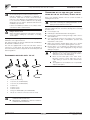
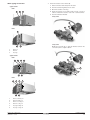
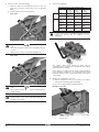
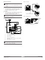
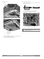
INSTALLATION MANUAL
2-way valve kit/3-way valve kit for fan coil units
EKMV2C09B7
EKMV3C09B7
EKMV2C09B7
EKMV3C09B7
2-way valve kit/3-way valve kit for fan coil units
Read this manual attentively before installation. Do not
throw it away. Keep it in your files for future reference.
Improper installation or attachment of equipment or
accessories could result in electric shock, short-circuit,
leaks, fire or other damage to the equipment. Be sure only
to use accessories made by Daikin that are specifically
designed for the use with the equipment and have them
installed by a professional.
If unsure of installation procedures or use, always contact
your dealer for advice and information.
CONNECTION
OF THE FAN COIL UNIT TO FIELD
PIPING BY USE OF THE 2-WAY/3-WAY VALVE
Refer to the installation manual of the fan coil unit for details on
installing the fan coil unit.
Be careful not to deform the unit piping by using excessive
force when connecting the piping. Deformation of the
piping can cause malfunction of the unit.
If air, moisture or dust gets in the water circuit, problems may occur.
Therefore, always take into account the following when connecting
the water circuit:
Danger: electric shock
■
Use clean pipes only.
Switch off all power supply before removing the control box
cover or before making any connections or touching
electrical parts.
■
Hold the pipe end downwards when removing burrs.
■
Cover the pipe end when inserting it through a wall so that no
dust and dirt enter.
■
Use a good thread sealant for the sealing of the connections.
The sealing must be able to withstand the pressures and
temperatures of the system.
■
When using non-brass metallic piping, make sure to insulate
both materials from each other to prevent galvanic corrosion.
■
Because brass is a soft material, use appropriate tooling for
connecting the water circuit. Inappropriate tooling will cause
damage to the pipes.
The English text is the original instruction. Other languages are
translations of the original instruction.
This option kit needs to be used in combination with an EKRP1C11
kit and a FWF or FWC fan coil unit.
The units are equipped with a water inlet and water outlet for
connection to a water circuit. This circuit must be provided by a
licensed technician and must comply with all relevant European and
national regulations.
ACCESSORIES
1
2
5
3
6
The unit is only to be used in a closed water system.
Application in an open water circuit can lead to
excessive corrosion of the water piping.
■
Never use Zn-coated parts in the water circuit.
Excessive corrosion of these parts may occur as
copper piping is used in the unit's internal water
circuit.
■
The equipment is not intended for use in a potentially
explosive atmosphere.
4
7
8
1
Actuator with toothed ring
2
2-way valve (only for EKMV2C09B7)
3
3-way valve (only for EKMV3C09B7)
4
Insulation tape
5
Insulation for valve
6
Installation manual
7
O-ring (1x for EKMV2C09B7) (2x for EKMV3C09B7)
8
Wire (in case 2 valves are connected on same fan coil unit)
■
KRP1B101 box and EKRP1C11 PCB are needed for
combination with the FWF units.
■
KRP1H98 box and EKRP1C11 PCB are needed for
combination with the FWC units.
Installation manual
■
SUPPLIED WITH THE KIT
2x
1
Installation manual
EKMV2C09B7 + EKMV3C09B7
2-way valve kit/3-way valve kit for fan coil units
4PW65144-1 – 10.2010
Water piping connections
2 pipe models
1
Mount the actuator on the valve body.
1 Remove the blue and red cap from the valve.
2 Push the toothed ring firmly onto the valve.
FWF
3 Mount the actuator on the ring.
1
2
4 Rotate the actuator 15° clockwise until you hear a "click". In
order to unfasten the actuator, rotate it 15° counterclockwise.
3
5 Push the red button inwards.
2-way valve
5
3
2
FWC
3
4
3-way valve
1
1
Water out
2
Water in
3
Air purge
2
Modify the inlet side (A) so that the distance between the
connection points is equal to 50 mm.
5
4 pipe models
3
FWF
1
2
5
6
2
4
50
m
m
A
3
4
FWC
1
5
6
3
4
2
1
Water out heating coil
2
Water in heating coil
3
Water out cooling coil
4
Water in cooling coil
5
Air purge heating coil
6
Air purge cooling coil
EKMV2C09B7 + EKMV3C09B7
2-way valve kit/3-way valve kit for fan coil units
4PW65144-1 – 10.2010
Installation manual
2
2
3
Mount the valve on the water piping.
Connect the field piping.
1 Install the o-ring in the water piping connection. In case of a
3-way valve, install the second o-ring in the second water
piping.
2 Install the valve on the inlet water piping
2 pipe
unit
2-way valve
4 pipe
unit
Required thread type on the field piping side
2-way
3-way
No valves
valve(s)
valve(s)
installed
installed
installed
Water in
3/4" male
3/4" female
3/4" female
BSP
BSP
BSP
Water out
3/4" male
3/4" male
3/4" female
BSP
BSP
BSP
Water in
3/4" male
3/4" female
3/4" female
Heating
BSP
BSP
BSP
Water out
3/4" male
3/4" male
3/4" female
Heating
BSP
BSP
BSP
Water in
3/4" male
3/4" female
3/4" female
Cooling
BSP
BSP
BSP
Water out
3/4" male
3/4" male
3/4" female
cooling
BSP
BSP
BSP
2
In case a 3-way valve is used, adjust the bypass opening to
regulate the pressure drop. See databook for more
information.
1
Pay attention to the
body.
mark on the 2-way valve
The arrow must point inside the inlet water piping of the fan
coil unit.
Make sure the actuator is not installed upside down.
3-way valve
The complete water circuit, inclusive all piping, must be
insulated to prevent condensation and reduction of the capacity
(minimum thickness: 10 mm).
If the temperature is higher than 30° and the relative humidity is
higher than 80%, the thickness of the sealing materials should
be at least 20 mm in order to avoid condensation on the surface
of the sealing.
2
1
4
Seal the valve and piping connections.
1 Add the "insulation for valve" (1) around the valve and the
sealing of the unit piping and the field piping.
2 Close the sealing off with the insulation tape (2).
Pay attention to the
body.
mark on the 3-way valve
Example: 3-way valve
The long arrow must point inside the inlet water piping of
the fan coil unit.
In case 2 valves are installed on the same fan coil unit
(4 pipe model), use the same method described above to
install the second valve.
2
1
2
Installation manual
3
1
Insulation for valve
2
Insulation tape
EKMV2C09B7 + EKMV3C09B7
2-way valve kit/3-way valve kit for fan coil units
4PW65144-1 – 10.2010
■
Electrical connections
Power supply
FWF
Do not drill any holes in the casing of the unit to install the
option.
PCB
Only use the accessories provided by Daikin to install the
option.
CN2
1 2 3
For the FWF
1
Install the KRP1B101 box and the EKRP1C11 PCB according to
the installation manual provided with the KRP1B101 kit.
For wiring of the EKRP1C11 PCB: see below.
X1 X2 X3 X4
F1U F2U
CN1
FWC
For the FWC
1
Install the KRP1H98 box and the EKRP1C11 PCB according to
the installation manual provided with the KRP1H98 kit.
For wiring of the EKRP1C11 PCB: see below.
The EKRP1C11 can only be used to connect the valves.
The functions mentioned in the installation manual of the
EKRP1C11 can not be used.
2
supplied with EKRP1C11 kit
■
L N
Communication wire
Wiring of the EKRP1C11
X35A
1
X21A
CN2
X33A for
FWF and
FWC
X27A
X11A
X1 X2 X3 X4
Y4
X10A
F1U F2U
CN1
supplied with EKRP1C11 kit
Y3
CN2
Y2
5
Y1
YC
4
6
2
X1 X2 X3 X4
F1U F2U
CN1
3
1
Communication to fan coil PCB
2
Power supply wire (to fan coil unit)
3
Fuses 5 A - 250 V
4
YC-Y1: connection of first valve
5
X1-Y4: wire to enable the use of the second valve (supplied
with valve kit)
6
X2-Y2: connection of second valve
Do not bundle low and high voltage wires together. Bundle
all wires with the included clamps in order to avoid contact
with fan coil PCB’s or sharp edges.
EKMV2C09B7 + EKMV3C09B7
2-way valve kit/3-way valve kit for fan coil units
4PW65144-1 – 10.2010
Installation manual
4
■
■
Wiring method
FWF
In case 2 valves are used:
Strip the wire of the valve motor of the second actuator for an
additional length of 50 mm.
4
3
1
50 mm
2
5
Connect X1 and Y4 with the wire supplied with the kit
(see "Accessories supplied with the kit", item 8).
5
1
FWC
2
5
4
1
X1-Y4 wire
2
X2-Y2: connection of the second valve
3
2
1
Communication wire
2
Power supply wire
3
First valve wire
4
Second valve wire
5
Tie wrap
1
For further installation of the fan coil units: refer to the fan
coil unit installation manual.
Never squeeze bundled cables and be sure that the cables do
not come in contact with sharp edges.
Cut off the redundant ends of the tie wraps.
Installation manual
5
EKMV2C09B7 + EKMV3C09B7
2-way valve kit/3-way valve kit for fan coil units
4PW65144-1 – 10.2010
NOTES
4PW65144-1 10.2010
Copyright 2010 Daikin