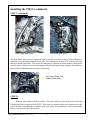
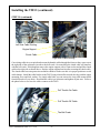
1
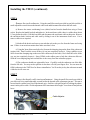
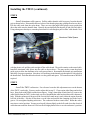
TM33 Pumper Carburetor Upgrade
For The Yamaha XT225
Installation Guide
and
Setup Instructions
TM33 Kit
Copyright 2004 ENDUCO, Inc.
TM33 Installation Guide V1.1 6/16
-1-
Introduction:
This manual describes the TM33 pumper carburetor and explains how to install it on the XT225
Yamaha motorcycle. Please read the information carefully to avoid problems with the installation.
The stock carburetor on the XT225 is a CV type. This means the carburetor’s slide is not under
direct control of the throttle cable but is, instead, operated by vacuum built up by a butterfly valve which
is controlled directy by the throttle cables. Carburetors of this type will exhibit a small hesitation during
acceleration due to the time required for the vacuum mechanism to move the throttle slide. Under
certain circumstances this delay may be objectionable to some riders. The TM33 carburetor allows
direct control over the throttle slide and includes an accelerator pump. This improves throttle response,
provides more confident acceleration and makes the bike a little more snappy off the line. This comes at
the expense of increased fuel consumption and emissions.
The TM33 carburetor may not meet current emission standards in some locations and therefore
would be considered an illegal modification for a street bike. Before installing the TM33 make sure you
understand the local emission laws in your riding area. Installing the TM33 kit does not require any
permanent changes to the bike, should it be necessary to put the stock carburetor back on the bike this
may be done easily.
It should be noted that the stock carburetor provides overall good performance. If you are
cruising the bike and want to maintain maximum gas mileage the TM33 kit will most likely not be an
enhancement. Although the stock carburetor may not deliver maxium power it does do a good job of
maintaining generally good performance. It also includes a coaster enrichment system that allows a
smooth “throttle up” after coasting the engine during down hill runs.
Since the TM33 carburetor includes an accelerator pump starting a cold bike is easier. A twist of
the throttle primes the engine and eliminates repeated stalling and stumbles common with the stock
carburetor.
Please read this manual carefully
Visit www.xt225.com for more information about the TM33 kit.
TM33 Installation Guide V1.1 6/16
-2-
Kit Contents:
The TM33 kit contains the following items:
1 Mikuni TM33-8012 Pumper Carburetor*
1 Aluminum Cable Spacer
4’ 5/16” Drain & vent hose
1 16” piece of 3/16” drain hose
1 Instruction Manual (PDF file)
3 Nylon zip ties
* The TM33 carburetor supplied in this kit has been modified to include a custom cable bracket and a
special jet needle.
DO NOT SMOKE AROUND GASOLINE
TM33 Installation Guide V1.1 6/16
-3-
Installing the TM33:
Overview:
Although the TM33 carburetor’s inlet and outlet flanges match those of the stock carburetor
other dimensional and mechanical differences exist. The installation steps supplied in this manual account for this and explain how to make a neat and clean installation that’s easily reversible should it be
necessary to restore the bike to stock condition. Please read these instructions carefully, use common
sense and good judgement during the installation process. Don’t force parts or over tighten screws and
bolts. Make sure to turn off the fuel petcock before beginning the installation. Spilled fuel presents a
potential fire hazzard. Don’t smoke around gasoline and have a fire extinguisher handy at all times. Do
not perform this installation on a hot engine or near an open flame. Make sure to work in a well
ventilated area at all times.
TOOLS YOU WILL NEED
10 & 12 mm sockets and rachet handle
Phillips head screw driver (medium bit size)
3 & 4 mm allen wrenches (hex key)
WD40 spray lubricant or equivilent
Bike tool kit
Small adjustable wrench
STEP 1
Remove the left and right plastic side panels that are in the center of the bike.
These panels are held in place by pins pressed into rubber grommets on the frame up near the seat and a
single phillips head screw down at the bottom of each panel. On some bikes the phillips screw includes
a plastic shoulder washer and retainer to keep the screw with the panel. Back out both of these phillips
head screws and make sure the panels are loose at the bottom. Pull the panels out of their rubber
grommets and remove them completely from the bike. The soft plastic may bend a little near the seat
during the removal process.
STEP 2
Remove the left and right air scoop panels on either side of the gas tank. These
panels are held in place by tabs on the gas tank, pins, grommets and a strap just in front of the engine’s
cylinder. A plastic pin with a rubber grommet on each panel engages a hole in the fuel tank flange. Pins
may be pulled from their grommets by hand. Using a 10mm socket remove the bolt on the strap. Spray
TM33 Installation Guide V1.1 6/16
-4-
Installing the TM33: (continued)
STEP 2 (continued)
with WD40 if required. If the bolt is stubborn, hold the strap with an adjustable wrench close to the
threads. With the strap loose pull scoop panel pins from grommets then slide the scoop panels forward
off the gas tank tabs. Small rubber grommets are on the gas tank tabs so make sure not to lose them.
STEP 3
Remove the seat. Using the 10mm socket remove the two bolts on either side of the seat.
These bolts are located just in front of the handles. With the bolts completely out, remove the seat by
lifting it up in the back and sliding it towards the back away from the tank.
STEP 4
Remove the gas tank. Using the 10mm socket remove the bolt that holds the rear of the tank
down . This includes the small flat bracket that craddles the tank in its rubber mounts. Turn off the fuel
petcock. Disconnect the rubber fuel hose by pinching the small clamping ring and pulling the hose off
the petcock barb fitting. Lift the tank just off the rubber mount. While pulling the tank towards the rear
of the bike rock the tank from left to right an inch or two until the tank slides off its front rubber mounts.
If the tank hasn’t been off the bike in a while you may need to pull strongly to break it loose from the
mounts. Do so carefully. Place the tank in a safe spot away from the bike and work area.
STEP 5
Clean the bike. Using a pressure washer or garden hose clean the bike around the carburetor
area and cylinder. USE CAUTION WITH HIGH PRESSURE WATER AROUND RUBBER BOOTS
TO PREVENT WATER FROM ENTERING SEALED AREAS! Remove all mud, road dust and
debris. DO NOT get dirt in the exposed fuel line. Washing prevents foreign matter from entering the
carburetor or engine intake port. Dry the carburetor area with a rag or compressed air.
DOUBLE CHECK
At this point you should have the carburetor, cables and cylinder head
completely exposed. This area should be free from dirt. The four
plastic panels, seat and gas tank should be in a safe place away from the
work area. Put loose hardware in a cup. Inspect the exposed area and
make sure nothing is damaged. Look for frayed cables, bad hoses or
damaged electrical wires. Fix, repair or replace as required.
TM33 Installation Guide V1.1 6/16
-5-
Installing the TM33: (continued)
STEP 6
Remove the stock carburetor. Using the small flat wrench provided in your bike tool kit or
small adjustable wrench loosen the throttle cable ends and disconnect them from the bell crank.
a) Remove the starter enrichening lever (choke) bracket from the handle bars using a 12mm
socket. Replace the handle bar bolt and tighten it. In the enrichener cable, there is a rubber boot (about
1/2 way down the cable). Pull this boot back and disconnect the enrichener cable at this point. Remove
the enrichener knob, bracket and cable stub by sliding it out of the instrument cluster area. Cut or
remove cable ties as required.
b) Snake all the drain/vent hoses up towards the carb so they are free from the frame and swing
arm. If there is an emission canister hose make sure that’s clear.
c) Using the 3mm allen wrench (hex key) loosen the clamping ring on the front of the carburetor
(engine side). Don’t back the screw all the way out just completely loosen it. Using a phillips screw
driver loosen the clamping ring on the rear of the carburetor (air box side). Don’t back the screw all the
way out just completely loosen it. Spray WD40 on the rubber parts to help the carburetor slide out.
Slide the rear clamping ring back towards the air box away from the carburetor spiquet.
d) The carburetor should now spin and be loose. Carefully work the carburetor out of the bike
from the left side. You may need to pull the air box hose off with your fingers first. You can store the
OEM carburetor in the TM33 box for future reinstallation. You’ll need to jockey the carburetor around
a little but it will come out.
STEP 7
Retract the throttle cable tension adjustment. Using the small flat wrench provided in
your bike tool kit or small adjustable wrench loosen the throttle cable adjustment jam nut. This nut is
located inside a rubber boot just off the throttle grip. On bikes with pull on/pull off cabling the adjustment is in the pull on cable. Set this adjustment in for maximum cable length. Leave boot off and jam nut
loose.
Cable Adjuster
TM33 Installation Guide V1.1 6/16
-6-
Installing the TM33: (continued)
STEP 8
Install aluminum cable spacer. Pull the rubber throttle cable boot away from the throttle
grip as shown below. Disassemble the two halves of the throttle grip using a phillips head screw driver.
Free the cable ends from the nylon drum. There are two right angle black plastic sweep guides that
direct the cable onto the throttle drum. Identify the one that pulls the throttle off (the forward cable).
Using a heat gun or hair dryer, warm the plastic until it’s soft enough to pull it off the cable sheath. Now
Aluminum Cable Spacer
with the plastic soft, pull the guide straight off the cable sheath. The guide remains on the actual cable.
Install the aluminum cable spacer into the cable as shown above. You may need to warm the plastic
guide again to allow the aluminum to be easily pressed into it. Reassemble the throttle grip mechanism
and check for proper operation. Note there is a small tang in the throttle grip that indexes with a hole in
the handle bars. Push the rubber boot back over the guides and spacer. Use a small amount of WD40 if
required.
STEP 9
Install the TM33 carburetor. For reference locate the idle adjustment screw on the bottom
of the TM33’s outlet side. You may need to adjust this in step 13. Clean engine inlet flange and air box
hose. Spray both with WD40 to make them slippery. Using a 4mm allen wrench (hex key) remove the
cable bracket from the TM33 via the single cap screw that holds the cable bracket plate to the carburetor’s
body. With the carburetor 90 degrees to the vertical (bell crank on top) work it onto the engine from the
left side of the bike. Slip the air box hose over the inlet and position the clamping ring in the hose’s
groove. Do not tighten anything at this time. The carburetor needs to remain loose. Rotate the carburetor into a vertical position. You may need to pull it down slightly so the bell crank clears the electrical
cable that runs under the frame rail. Refer to the left/right photos below to see the carburetor’s position.
TM33 Installation Guide V1.1 6/16
-7-
Installing the TM33: (continued)
STEP 9 (continued)
TM33 Right Side View
TM33 Left Side View
The photo below shows how the carburetor aligns vertically. Note the rear screw on the carburetor’s
black top cover just hidding under the frame boss. There should also be about 1/16” clearance between
this screw and the frame boss. This allows the carburetor to vibrate in its rubber mounts without metal
to metal contact. Make sure this is so then tighten both inlet and outlet clamps using the 3mm allen key
(hex wrench) and phillips head screw driver respectively.
Top Cover Screw Just
Under Frame Boss
STEP 10
Reroute and connect throttle cables. The stock carburetor controls the throttle from the
left hand side which is opposite to the TM33. This requires to throttle cables to be rerouted to the right
side of the bike. Enough length is available in the stock cables to accomplish this. Refer to the photos
below to see how the cables are rerouted.
TM33 Installation Guide V1.1 6/16
-8-
Installing the TM33: (continued)
STEP 10 (continued)
Left Side Cable Routing
Engine Support
Clutch Cable
Right Side Cable Routing
Cut existing cable ties as required and reroute the throttle cables through the frame so they come out on
the right side of the carburetor just above the bell crank. On some bikes the clutch cable will interfere
with the bell crank. If this happens remove the engine support with a 12mm socket and pull the clutch
cable to the right side as shown above. Replace engine support bracket after rerouting the clutch cable.
The clutch cable has extra protection around its sheath so make sure this is in proper position to avoid
cable damage. Install the cable bracket to the TM33 using a 4mm allen wrench (hex key) and the single
mounting screw and lock washer. For single cable bikes you can remove the extra cable mount block
from this bracket if you desire. Hook throttle cable(s) to carburetor and tighten all jam nuts. Refer to
the photo below to see how the cables connect to the TM33.
Pull Throttle On Cable
Pull Throttle Off Cable
The Bell Crank
TM33 Installation Guide V1.1 6/16
-9-
Installing the TM33: (continued)
STEP 10 (continued)
Using the nylon zip ties provided in the kit, cinch down the cables as required to make sure everything is
tight, not rubbing and in proper position. Set the cable length adjuster to remove any slop in the throttle
grip, tighten its jam nut and replace the rubber boot. Make sure throttle snaps back to idle without drag
or hesitation. Check for smooth operation of the throttle and inspect the bell crank to make sure it is able
to move freely. Adjust and/or correct throttle action as necessary. While watching the bell crank move
the handle bars completely left to right and right to left. Make sure not to move the throttle grip while
steering. During the above steering action (lock to lock), cables shouldn’t pull and the bell crank should
remain stationary.
STEP 11
Install Hoses. Using the supplied hose in the kit hook up the left and right vent hoses on the
TM33’s aluminum barb fittings. They are located on center with the carburetor’s bore on each side.
These barb fittings point down towards the ground. Using the smaller hose hook up the bowl fuel drain.
Fuel drain nipple is on the bottom of the bowl. Feed hoses down behind the swing arm towards the
ground. Make sure to route hoses so they don’t get pinched or damaged when the bike is operated.
Keep them clear of the exposed clutch cable. Make sure they will drain away from the bike’s frame and
swing arm. Cut lengths accordingly. Remove the black fuel inlet hose from the stock carburetor and
install it on theTM33’s brass fuel inlet barb fitting. Make sure to use both stock squeeze clamps. WD40
can be used to help push the fuel line hose onto the TM33 since its barb fitting is slightly larger than the
stock carburetor’s fuel inlet.
DOUBLE CHECK
At this point you should have the TM33 carburetor installed. Throttle
cabling should work properly and be cinched down with zip ties. All
bolts, jam nuts and clamps should be tight. The cable spacer should be
installed and all rubber boots returned. The throttle should operate
smoothly with no slop or drag. The bell crank should be free to move
and not touch any metal. The TM33 should be free to vibrate in its
rubber mounts without any metal to metal contact. Drain hoses should
be installed and free from possible cuts, wearing or pinching. Fluids
should be conducted down and away from the bike.
TM33 Installation Guide V1.1 6/16
- 10 -
Installing the TM33: (conclusion)
STEP 12
Install the gas tank. Spray some WD40 on the two round rubber mounts that hold the front
of the gas tank. Slide the gas tank back into position and reinstall the bracket that holds down the back
of the tank. Push the fuel line hose onto the fuel petcock barb fitting. Position the small hose pinch
clamp. Turn on the fuel and make sure no fuel leaks are present.
STEP 13
Starting the bike. At this time the bike can be started. Pull the enrichener knob all the way
out and twist the throttle a couple of times to squirt fuel into the bore. The bike should start easily and
fast idle. After 15 - 30 seconds you can push the enrichener knob to the second position and let the bike
warm up for a few minutes. After the bike is warm push the enrichener knob all the way in and adjust the
idle speed. There is a small thumb screw that adjusts the idle speed towards the bottom of the TM33 on
the left. There is also a small idle jet screw just on the underside of the TM33’s outlet. If necessary use
a small short screw driver to adjust this for best idle performance. Turning the screw out richens the
mixture. The bike will idle best if set slightly on the rich side. Once all adjustments are made, quickly roll
the throttle on to make sure the engine accelerates crisply. Keep in mind that the XT225 will run lean
when cold and much richer when hot. Best performance should occur when the bike is at a stable
operating temperature.
STEP 14 - Final Step
Install the seat and plastic panels. Install the seat and the four plastic panels that were
removed at the beginning of this procedure. Spray some WD40 on the rubber grommets to assist in
reassembly. With the seat and plastic panels in position the bike should be completely reassembled at this
time and ready for normal operation. Your TM33 has been completely installed. At this time the bike
can be test ridden.
TM33 Installation Guide V1.1 6/16
- 11 -
Performance and Tuning the TM33:
PERFORMANCE NOTES
The TM33 pumper carburetor includes an accelerator pump mechanism and a throttle slide
which is under direct control of the throttle cables. The accelerator pump squirts a small amount of fuel
directly into the intake port as soon as the throttle is moved from a closed position to slightly open.
Throttle positions slightly beyond open do not actuate the accelerator pump. This is a normal design for
motorcycle carburetors of this type. The TM33 does not include any accelerator pump adjustments.
Timing the accelerator pump in this way helps the engine accelerate crisply from idle. By twisting the
throttle slightly, the accelerator pump also primes the engine and greatly assists in cold starting.
Direct contol over the throttle slide allows the rider roll on the throttle at an appropriate rate to
suit riding conditions. The engine will respond immediately to acceleration requests. It should be noted
that instantly snapping the throttle wide open from idle will cause the engine to stall. This situation does
not represent a jetting problem but is normal for 4 stroke engines with venturi type carburetors. Snapping the throttle “full on” opens the entire carburetor bore to an idling engine. The resultant rapid drop
in the velocity of air passing through the carburetor bore prevents fuel from being drawn out of the bowl,
atomized and sucked into the intake port. This sudden loss of fuel will stall the engine before it has a
chance to catch up. To rapidly accelerate the engine, the throttle should be rolled on quickly. Using this
technique will provide for quick snappy acceleration.
Lugging the engine (not down shifting properly) then calling for rapid acceleration may cause
hesitation. Adequate RPM should be maintained to ensure proper venturi action and atomizing of fuel.
This will allow for the best acceleration and performance.
Increased power and acceleration come at the expense of emissions and fuel economy. The
TM33 pumper carburetor will use more fuel than the stock CV carburetor. As such it will also produce
more emissions making it an illegal upgrade in those places where street legal motorcycle emissions are
strictly monitored. Make sure to understand your local emissions laws and abide by them. In places
where the XT225 is used off-road emissions may not be a consideration. It is your responsibility to
know local emission laws and operate your bike accordingly. The TM33 kit doesn’t require any permanent modifications to the bike so the stock “street legal” CV carb may be put back on the bike if required.
TM33 Installation Guide V1.1 6/16
- 12 -
Performance and Tuning the TM33: (continued)
TUNING THE TM33
The TM33 pumper carburetor has been jetted to work properly in 68 degrees F with a generic
XT225 engine at sea level with stock exhaust. Altitude, temperature and engine conditions will play a
major role in how well the TM33 performs on a specific bike. Other factors like humidity and fuel grade
will also affect how the carburetor functions. In most cases adjustments will not be required but should
they be necessary the information presented here will be helpful. It is suggested that these adjustments
be performed by those experienced with motorcycle carburetors and repairs.
Two adjustments can be performed on the TM33 to alter its air fuel ratio allowing the carburetor
to run richer or leaner. The first of these adjustments involves moving the e-clip on the jet needle which
will richen or lean out the mixture over throttle ranges from 1/4 to 3/4 open. The default e-clip setting
is mid position which allows two settings in either the rich or lean direction. Moving the e-clip up leans
the mixture and moving it down richens the mixture. The second adjustment is to replace the main jet
with a different size. A larger main jet increases fuel flow. The main jet will affect the entire throttle
range but has most of its impact on 3/4 to wide open throttle.
A rich mixture is characterized by an heavy exhaust smell and excessive fuel consumption. Operating the bike in high altitudes or very hot dry weather may cause the mixture to run rich. A lean
mixture is characterized by hesitation, stumbling and general poor acceleration. Before the carburetor is
suspected of a poor match to the engine, make sure to eliminate other problems like ignition and/or
clogged air box. Before attempting any carburetor tuning the engine should be in generally good condition and the air filter cleaned.
ADJUSTING THE JET NEEDLE
Refer to the exploded view of the TM33-8012 at the end of this manual to identify the carburetor’s parts.
This adjustment can be made without removing the carburetor from the bike.
STEP 1 - Turn off the fuel petcock. Run the carburetor out of fuel. Remove the 4 plastic cowl panels.
Disconnect the fuel line. Remove the seat and fuel tank to expose the carburetor. Loosen the clamps on
the inlet and outlet of the carburetor. Remove the single screw that holds the throttle cable bracket to
the TM33’s body. Pull this bracket loose from its index pin. You do not need to remove the throttle
cables.
STEP 2 - Carefully rotate the top of the TM33 towards the left side of the bike to allow access to the
top cover (2). You will need to push down on the carburetor so the bell crank clears the wiring harness.
The top cover (2) and top cover screws (1) should be exposed. Remove the top cover (2).
TM33 Installation Guide V1.1 6/16
- 13 -
Performance and Tuning the TM33: (continued)
ADJUSTING THE JET NEEDLE
(continued)
STEP 3 - Using a small socket remove the throttle lever bolt (58). Lift the throttle lever (58) up to
draw the throttle valve (9) to its fully open position. Using a 2.5mm allen wrench (hex key) loosen the
joint assembly screws (4). Remove the joint assembly (5) from the throttle valve (9).
STEP 4 - With the joint assembly (5) clear remove the throttle valve (9) from the TM33. Remove the
jet needle (8) from the throttle valve (9). Don’t lose the packing washer (7).
STEP 5 - Place the jet needle (8) down on a flat surface with the e-ring (6) split facing down. Just
behind the e-ring (6), press the jet needle (8) down with your thumb to free it from the e-ring (6). Move
the e-ring (6) to the desired position on the jet needle (8). Snap it into place. Put the jet needle (8) back
into the throttle valve (9).
STEP 6 - Reassemble the TM33 and put the top cover (2) back on.
STEP 7 - Return the TM33 to its original upright position and reattach the throttle bracket.
STEP 8 - Install fuel tank and hook up fuel line. Replace seat and plastic panels.
STEP 9 - Test ride bike and repeat jet needle adjustments as required.
REPLACING THE MAIN JET
Refer to the exploded view of the TM33-8012 at the end of this manual to identify the carburetor’s parts.
This adjustment requires removing the carburetor from the bike. It is a good idea to clean the bike’s
carburetor area to prevent foreign matter from accidentally entering the engine.
STEP 1 - Turn off the fuel petcock. Run the carburetor out of fuel. Remove the 4 plastic cowl panels.
Disconnect the fuel line. Remove the seat and fuel tank to expose the carburetor. Loosen the clamps on
the inlet and outlet of the carburetor. Slide the inlet clamp back towards the air box. Remove the single
screw that holds the throttle cable bracket to the TM33’s body. Pull this bracket loose from its index pin
and remove the throttle cables from the bell crank.
STEP 2 - Remove all the vent/drain hoses from the TM33. Place an absorbant cloth under the TM33
to catch fuel spills. Spray some WD40 on the inlet and outlet of the carburetor to reduce friction. Turn
the top of the TM33 towards the left side of the bike so the bell crank is facing up. Carefully work the
TM33 out of the bike.
TM33 Installation Guide V1.1 6/16
- 14 -
Performance and Tuning the TM33: (continued)
REPLACING THE MAIN JET
(continued)
STEP 3 - Place the TM33 on a clean towel. Remove the single long float bowl screw (33) and three
short float bowl screws (34). Carefully remove the bowl making sure not to bend the dip tube or lose the
A/P plunger (44) and spring (43). Try to avoid letting gasoline contact the float bowl O-ring (29) as this
will cause it to expand making reassembly difficult. If the O-ring expands, simple dry it off and let it
return to its original size before attempting reassemble.
BE CAREFUL NOT TO DAMAGE THE FLOATS OR CHANGE THEIR ADJUSTMENT
STEP 4 - With the main jet (27) now exposed use a large straight blade screw driver to remove it.
Replace the main jet (27) with the desired size. Numbers are stamped on the jets to indicate size. Larger
numbers move towards a richer mixture.
STEP 5 - Reassemble the TM33 and install it back in the bike. Re-attach all vent/drain hoses. Tighten
clamps. Connect the throttle cable and check for proper unobstructed operation. Replace the fuel tank
and hook up the fuel line. Install the seat and plastic cowlings.
STEP 6 - With the bike completely assembled turn the fuel petcock on and make sure there are no fuel
leaks. Test run the bike and check for proper performance. Change main jet sizes as required to achieve
desired performance.
ALWAYS RIDE UNDER CONTROL
TM33 Installation Guide V1.1 6/16
- 15 -
703XPSHU&DUE
1R 'HVFULSWLRQ
3DUW1XPEHU
&: 70D
70
70
90
90
-)3
70
90
70
90
%6
%6
70
1
90
1
90
.9
90
70
90
1
90
1
70
)
& & 1
70
70
1
1
90
1
(
70
1
70
%
90
70
70FF
& 70
70
70
%
90
: 90
90
90
0
%6:
%L
70
1
3
6FUHZ7RS&RYHU
7RS&RYHU
*DVNHW7RS&RYHU
6FUHZ-RLQW$VV\
-RLQW$VV\
(5LQJ
3DFNLQJ
-HW1HHGOH
7KURWWOH9DOYH
*DVNHW$LU)XQQHO
+RVH9HQW
$LU)XQQHO
6FUHZ$LU)XQQHO
3LORW$LU6FUHZ
0DLQ$LU-HW
6SULQJ,GOH$GMXVWHU
,GOH$GMXVWHU
&OLS,GOH$GMXVWHU
3LQ)ORDW
)ORDW$VV\
1HHGOH9DOYH$VV\
6FUHZ9DOYH+ROGHU
25LQJ1HHGOH9DOYH
)LOWHU1HHGOH9DOYH
5LQJQ\ORQ0DLQ-HW
5LQJEUDVV0DLQ-HW
0DLQ-HW
3LORW-HW
25LQJ)ORDW%RZO
'UDLQ6FUHZ)ORDW%RZO
)ORDW%RZO
+RVH2YHUÀRZ
6FUHZORQJ)ORDW%RZO
6FUHZVKRUW)ORDW%RZO
25LQJ$31R]]OH
$31R]]OH
3OXJ$31R]]OH
3LORW6FUHZ
6SULQJ3LORW6FUHZ
:DVKHU3LORW6FUHZ
25LQJ3LORW6FUHZ
+RVH9HQW
6SULQJ$33OXQJHU
$33OXQJHU
&DS$35RG
5RG$3
%ROW$3/HYHU
/HYHU$3
6SULQJ$3/HYHU
0DLQ%RG\
6FUHZ7KURWWOH%UDFNHW
7KURWWOH%UDFNHW
%HOOFUDQN
6SULQJ7KURWWOH5HWXUQ
3DFNLQJ7KURWWOH6KDIW
/HYHU7KURWWOH
:DVKHU7KURWWOH/HYHU
%ROW7KURWWOH/HYHU
6SULQJ/LQNDJH/HYHU
3ODWH/LQNDJH/HYHU
:DVKHU/LQNDJH/HYHU
(5LQJ/LQNDJH/HYHU
3DFNLQJ/LQNDJH/HYHU
&KRNH$VV\
25LQJ&KRNH$VV\
1HHGOH-HW
TM33 Installation Guide V1.1 6/16
- 16 -