1
œ
œ
œ
œ
œ
œ
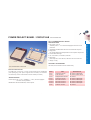
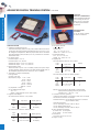
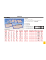
AD SERIES
MATERIAL
AD-11
AD-01
AD-101
External Body is made of ABS.
AD-4D
AD-12
The internal interconnected clips are made of following materials
MODEL NO. with last character of N: Nickel Plated
AD-100
S: Silver Plated
AD-102
AD-4D 48 Tie points
AD-10
AD-100 360 Tie points
AD-101 408 Tie points
AD-102 456 Tie points
AD-01 948 Tie points
AD-10 Power Block with Binding post
AD-11 Power Block & 958 Tie points
AD-13
AD-12 Power Block & 1906 Tie points
AD-13 Power Block & 2854 Tie points
AD-14
AD-14 Power Block & 3802 Tie points
SNAP LOCK
ROUND HOLE
SPECIFICATION
MODEL
DIMENSION (m / m)
LENGTH WIDTH HEIGHT
TIEPOINTS
6 interconnected
CLIP
12 interconnected
CLIP
24 interconnected
CLIP
TERMINAL
BACKPLATE
WEIGHT
(g m)
AD-4D
81
12
9
48
0
2
1
0
STICKER
10
AD-100
81
42
9
360
60
0
0
0
STICKER
30
AD-101
81
52
9
408
60
2
1
0
STICKER
40
AD-102
81
62
9
456
60
4
2
0
STICKER
50
AD-10
81
30
19
10
0
0
0
5
STICKER
20.4
AD-01
83
118
9
948
142
4
2
0
STICKER
77.8
AD-11
83
147
19
958
142
4
2
5
STICKER
98.8
254.4
AD-12
184
168
24
1906
284
8
4
5
ABS
plastic
AD-13
266
168
24
2854
426
12
6
5
ABS
plastic
367.6
AD-14
346
168
24
3802
568
16
8
5
ABS
plastic
490.0
œ
œ
œ
œ
œ
œ
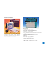
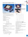
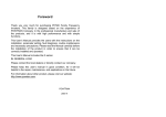
AC/DC POWER SUPPLY FOR BREADBOARD
PSB-01
WITH BUILT-IN SHORT-PROOF REGULATED
POWER SUPPLIES
œ
Power switch with lamp.
œ
Just plug in and start to use.
œ
Compact and light-weighted.
œ
For both digital/analog circuits.
SPECIFICATIONS
1. DC power supply:
œ
DC + 5 V, 1 A; - 5 V, 500 mA. fixed.
œ
DC 0 to + 15 V, 500 mA variable.
œ
DC 0 to - 15 V, 500 mA variable.
2. AC power supply:
AC voltage: 12 V - 6 V - 0 V - 6 V - 12 V, 300 mA fixed.
3. Size: 185(L) x 155(W) x 66(H) with stand (mm)
4. Weight: 3 Kg
ACCESSORIES
œ
AC cable x 1
œ
DC output wires. Red x 4, Black x 1
Ų
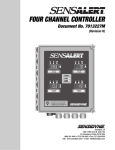
UC-06
DIGITAL TRAINER
Centronic connector
36 contacts
11
10
DT-01
9
1
8
2
3
4
7
5
6
SPECIFICATIONS
1. AC adaptor jack: I/P DC + 8 V, 1.5 A
2. Pulse switch.: Two bounce-free pushbuttons.
3. Logic switch.: Eight logic level switches in DIP type.
4. DC O/P: DC + 5 V, 750 mA for user.
5. B-023 breadboard: Solderless breadboard with 1580 interconnected
tie points.
For breadboard, digital circuits, flip-flops and monostable
6. Clip terminal: Logic probe clip terminal.
multivibrators, counters, encoders, decoders, multiplexers,
7. LED display: Eight LED buffered logic level indicators.
demultiplexers and sequencers, resistor, LED and 7
8. BNC jacks.
segments LED displays, memory devices, etc.
9. Select switch.: Clock range selection.
L:10 - 40 Hz. H:1K - 20K Hz.
10. Banana jacks.
11. Clock adj.: Fine adj. of clock frequency.
ACCESSORIES
1. ADP-01 AC Adaptor 2. LP-2800 Logic Probe 3. User's Guide
POWER PROJECT BOARD / CIRCUIT LAB
PP-272/PBU-312
PP-272 POWER PROJECT BOARD
SPECIFICATIONS
Variable power 0 ~ Ų15 V/500 mA Equipped with short circuit
protection.
2. Solderless breadboard RH-53 interconnected 2420 tie points.
3. Edge plate:
EP-3 edge plate for the best placement of non-dip size components.
4. Power switch with light
5. AC 110 V/220 V, 120 V/240 V, 50/60 Hz
6. Dimension:
Main body 250 x 200 x 80 m/m, With box 305 x 235 x 85 m/m
7. Weight. 2.5 Kg.
PP-272
PP-312
OPTIONAL ACCESSORIES
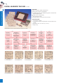
UC series, the universal connector socket family.
FOR LABORATORY PURPOSE
PBU-312 CIRCUIT LAB
The PBU-312, Circuit Lab. is a low cost but ideal tool for breadboard
(said prototyping) with power supplies and necessary environment
connections by means of Universal connector socket (UC series)
SPECIFICATIONS
Power supply: DC + 5 V/1 A, Variable 0 ~ Ų15 V, 500 mA. equipped
with short circuit protection.
Breadboard: AD-202 breadboard, 1992 tie points.
Model
UC-01
UC-02
UC-03
UC-04
UC-05-3
UC-05-6
UC-05-9
UC-06
ITEM
Card edge connector
D-sub connector
Straight header connector
Card edge connector
DIN 41612 connector
DIN 41612 connector
DIN 41612 connector
Centronic connector
DESCRIPTION
62 contacts, 2.54mm pitch
25 contacts, male & female
60 contacts
56 contacts, 3.96mm pitch
32 contacts, 5.08mm pitch
64 contacts, 2.54mm pitch
96 contacts, 2.54mm pitch
36 contacts
Electronic Educational Systems
1. DC power +5 V/1 A
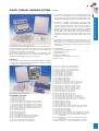
ANALOG OVERLAY LEARNING SYSTEM
OLS-1000
œ
The OLS-1000 overlay learning system gives you an electronic
template which guides your students to an immediate and
rational experimental layout while the course software relates to
Electronic Educational Systems
the traditional circuit diagram.
œ
The OLS-1000 analog overlay learning system is compatible
with K&H products of IDL-600 analog lab, training system, and
ETS-7000 digital-analog Training system, and K&H series proto
board.
œ
No add-ons are required. A standardised set of all necessary
components is included. The thoroughly researched course
software was designed by educators with over 20 years practical
teaching experience and the experiments were especially
stressed on the theory rather than further confuse the students.
The professionally produced manuals are referred to the most
widely used theory books. The schematic diagrams component
listing and procedure are clearly listed. Each experiment was
COMPATIBLE WITH ETS-7000 DIGITAL-ANALOG TRAINING SYSTEM
tested for typical students reaction prior to final editing.
Electronics could be taught straight out of a book if the students were
able to visualise the function of an experimental circuit. Unfortunately this
is rarely the case and until now it has been necessary to laboriously
assemble every experiment to be examined.
œ
No prerequisites are demanded other than basic arithmetic. The
emphasis is on an instrumental understanding rather than a
mathematical one. The continuous hands-on exposure ensures
The assembly of each circuit has no didactic value whatsoever other
the transfer of marketable technological skills in the minimum
than to provide the student with a circuit on which to do the experiment.
amount of time.
Now the OLS-1000 overlay learning system is coming.
Standard package:
FEATURES:
œ
1. Circuit diagram (tracing paper): 28 pcs
The OLS-1000 overlay learning system allows the student to assemble
2. Experiment book: 1 pce
even the most involved circuit in less than five minutes thus leaving
3. Components: 1 set
enough time for fruitful experimentation.
4. RM-203 breadboard: 1 pce
5. Dimensions: 290 x 225 x 55 mm (L x W x H)
6. Weight: 1.3 Kg
6. The use of a diode bridge in AC circuits.
7. Filtering and regulation of a pulsating DC voltage.
8. An experimental power supply using a "Pl" filter.
9. Voltage multiplying using diodes & capacitors: voltage doubling.
10. DC current gain of a common emitter transistor configuration.
11. The common emitter as an AC amplifying stage.
12. Cascaded stages of amplification.
13. Class a single-ended loudspeaker driven audio amplifier.
14. The class a push-pull audio amplifier.
15. Complementary-symmetical push-pull output circuits.
16. The field effect transistor: the common-source amplifier.
17. Oscillator circuits: The zero-phase shift oscillator.
18. Oscillator circuits: The phase-shift oscillator.
19. Oscillator circuits: The armstrong oscillator.
20. Oscillator circuits: The hartley oscillator.
21. Oscillator circuits: The colpitts oscillator.
22. Digital integrated circuits: The AND gate.
STANDARD SYSTEM PACKAGE
EXPERIMENT CONTENTS:
1. Semiconductor silicon diodes in DC circuits.
2. Light emitting diode in DC circuits.
3. Silicon diodes in AC circuits: half wave rectification.
4. Silicon diodes in AC circuits: full wave rectification.
5. The use of a diode bridge in DC circuits.
23. Digital integrated circuits: The OR gate.
24. Digital integrated circuits: The AND-OR function.
25. Digital integrated circuits: The inverting gate.
26. Digital integrated circuits: The NAND gate.
27. Digital integrated circuits: The NOR gate.
28. Digital integrated circuits: The full adder.
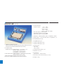
DIGITAL OVERLAY LEARNING SYSTEM
Electronics could be taught straight out of a book if the students were
able to visualise the function of an experimental circuit. Unfortunately this
is rarely the case and until now it has been necessary to laboriously
assemble every experiment to be examined.
The assembly of each circuit has no didactic value whatsoever other
than to provide the student with a circuit on which to do the experiment.
Now the OLS-2000 overlay learning system is coming:
œ
The OLS-2000 overlay learning system is compatible with K&H
products of IDL-800 digital lab. DT-01 digital trainer, PP-272
power project board, ETS-5000 advanced digital system, ETS7000 digital-analog training system and K&H series proto-board.
œ
No add-ons are required. A standardised set of all necessary
components is included. The thoroughly researched course
software was designed by educators with over 20 years
practical teaching experience and the experiments were
especially stressed on the theory rather than further confuse the
students. The professionally produced manuals are referred to
the most widely used theory books. The schematic diagrams
component listing and procedure are clearly listed. Each
experiment was tested for typical students reaction prior to final
editing.
œ
No prerequisites are demanded other than basic arithmetic. The
emphasis is on an instrumental understanding rather than a
mathematical one. The continuous hands-on exposure ensures
the transfer of marketable technological skills in the minimum
amount of time.
Standard package
1. Circuit diagram (tracing paper): 62 pcs
2. Experiment book: 1 pce
3. Components: 1 set
4. RM-203 breadboard: 1 pce
5. Dimensions: 290 x 225 x 55 mm (L x W x H)
6. Weight: 1.4 Kg
FEATURES
œ
The OLS-2000 overlay learning system allows the student to assemble
even the most involved circuit in less than five minutes thus leaving
enough time for fruitful experimentation.
STANDARD SYSTEM PACKAGE
EXPERIMENT CONTENTS
1. FE-01 basic logic functions
2. FE-02 basic logic functions
3. FE-03 basic logic functions
4. FE-04 basic logic functions
5. FE-05 boolean algebra and simplification of logic equations
6. FE-06 boolean algebra and simplification of logic equations
7. FE-07 boolean algebra and simplification of logic equations
8. FE-08 boolean algebra and simplification of logic equations
9. FE-09 boolean algebra and simplification of logic equations
10. FE-10 boolean algebra and simplification of logic equations
11. FE-11 demorgan's theorem
12. FE-12 demorgan's theorem
13. FE-13 demorgan's theorem
14. FE-14 demorgan's theorem
15. FE-15 demorgan's theorem
16. FE-16 TTL NAND/NOR gates definitions and operation
17. FE-17 NAND/NOR gates definitions and operation
18. FE-18 the "exclusive-OR" and its applications
19. FE-19 the "exclusive-OR" and its applications
20. FE-20 the "exclusive- OR" and its applications
21.
22.
23.
24.
25.
26.
27.
28.
29.
30.
31.
32.
33.
34.
35.
36.
37.
38.
39.
40.
41.
42.
43.
44.
45.
46.
47.
48.
49.
50.
51.
52.
53.
54.
55.
56.
57.
58.
59.
FE-21
FE-22
FE-23
FE-24
FE-25
FE-26
FE-27
FE-28
FE-29
FE-30
FE-31
FE-32
FE-33
FE-34
FE-35
FE-36
FE-37
FE-38
FE-39
FE-40
FE-41
FE-42
FE-43
FE-44
FE-45
FE-46
FE-47
FE-48
FE-49
FE-50
FE-51
FE-52
FE-53
FE-54
FE-55
FE-56
FE-57
FE-58
FE-59
the "exclusive- OR " and its applications
the "exclusive- OR" and its applications
the "exclusive- OR" and its applications
the "exclusive- OR " and its applications
full-adder and full-subtractor
full-adder and full-subtractor
full-adder and full-subtractor
full-adder and full-subtractor
full-adder and full-subtractor
bistable or flip-flop(FF)
bistable or flip-flop(FF)
bistable or flip-flop(FF)
binary counters and the binary number system
binary counters and the binary number system
divide-by-n counters and decade counters
divide-by-n counters and decade counters
divide-by-n counters and decade counters
divide-by-n counters and decade counters
divide-by-n counters and decade counters
shift registers and ring counters
shift registers and ring counters
shift registers and ring counters
shift registers and ring counters
pulse forming and shaping; the schmitt trigger
pulse forming and shaping; the schmitt trigger
integrated-circuit timers-the 74122, 74121, and 555
integrated-circuit timers-the 74122, 74121, and 555
decoding and encoding
decoding and encoding
decoding and encoding
decoding and encoding
random-access memories (RAM) scratch pad memories
random-access memories (RAM) scratch pad memories
the operational amplifier
the operational amplifier
the operational amplifier
digital-to-analog (D/A) and analog-to-digital (A/D) conversion
digital-to-analog (D/A) and analog-to-digital (A/D) conversion
complementary symmetry MOS (CMOS)-principles and
characteristics
60. FE-60 complementary symmetry MOS (CMOS)-principles and
characteristics
61. FE-61 complementary symmetry MOS (CMOS)-TTL interface
62. FE-62 complementary symmetry MOS (CMOS)-TTL interface
Electronic Educational Systems
COMPATIBLE WITH IDL-800 DIGITAL LAB
OLS-2000
LOGIC TRAINER
IDL-400
SPECIFICATIONS
Electronic Educational Systems
The IDL-400 logic trainer is designed for the logic beginners to enhance
the comprehension of basic logical theory. The design of IDL-400 is easy
to operate and easy to understand. It is equipped with various kinds of
basic logic gates, debounced logical switches, LED indicators, DC power
supply with short circuit protection, pulse generator and solderless
breadboard.
1. Basic logic gate units:
It contains 6 kinds of logic gates, i.e. AND gate X 6, OR gate X 6,
NAND gate X 6, NOR gate X 6, OR gate X 3, NOT gate X 3.
Input voltage of Hl level > 2.25 V
Input voltage of LO level < 0.8 V
2. DC power supply: Equipped with short circuit protection and indicator.
a. output voltage +5 VŲ5 %
Max. output current 1 Amp.
Line regulation<50 mV
Load regulation<100 mV
b. Output voltage - 5 VŲ5 %
Max. output current 500 mA
Line regulation<25 mV
Load regulation<30 mV
R: 100 Kɖ
c. Output voltage Ų15 VŲ5 %
C: 0.01ɢF
Max. output current 500 mA
IC: 74LS14
Line regulation<150 mV
Load regulation<150 mV
3. Pulse generator:
3 kinds of time interval, 1 sec, 0.1 sec, 0.01 sec. Output voltage +5V
4. Debounced logic switch: HI/LO
5. 8 bits LED output indicator: Max. input voltage ŷ15 V DC
6. Solderless breadboard: AD-200
Interconnected 1896 tie points, fitting all DIP sizes and all
components with lead and solid wire AWG #22~30 (0.3~0.8 mm)
7. Accessories:
œ Power cord
œ User manual
8. Dimensions: 420 x 360 x 200 mm (L x W x H)
9. Weight: 4.2 Kg
ɖ
ɢ
ɖ
Ų
Ų
ɖ
ɢ
Ų
ŷ
œ
ANALOG LAB
œ
IDL-600
3. Function generator:
Frequency ranges
1 Hz ~ 10 Hz
10 Hz ~ 100 Hz
100 Hz ~ 1K Hz
1K Hz ~ 10K Hz
10K Hz ~ 100K Hz (5 ranges)
Sine wave output: 0~8 Vpp variable.
Triangle wave output: 0~6 Vpp variable.
Square wave output: 0~8 Vpp variable.
4. Voltmeter: 0 - 30VDC full scale, calss 1.5, impedance = 320Kɖ.
5. Ampere meter: 0 - 100ɢA full scale, class 1.5, impedance = 1ɖ.
6. Pin tip/banana jack: 2 pcs
7. Pin tip/BNC jack: 2 pcs
8. 2 positions slide switch: 2 pcs
1. Solderless breadboard: AD-200
Interconnected nickel plated 1896 tie points, fitting all DIP sizes and all
components with solid leads AWG #22-30 (0.3-0.8mm).
9. 3 positions slide switch: 1 pce
10. Potentiometer:
VR1 =1Kɖ
VR2 = 100Kɖ
2. DC power supply:
Variable DC power: Output voltage 0 ~ +15 V and 0 ~ -15 V.
11. 6 positions rotary switch: 1 pce
Maximum output current 300 mA.
Line regulation < 0.05%/V(at 25ƨ)
12. Speaker: 2 1/4", 8ɖ
Load regulation < 30 mV(at 25ƨ.)
13. Accessories:
+5 VDC power supply: Output voltage 5V Ų 0.25 V(no load to full load).
œ
Power cord
œ
User manual
Maximum output current 1 Amp.
-5 VDC Power Supply: Maximum output current 100 mA.
All DC power supplies equipped with short-circuit protection.
14. Dimensions: 420 x 360 x 200 mm (L x W x H)
15. Weight: 4.2 Kg
DIGITAL LAB
IDL-800
5. Two digits of 7 segment LED display:
Common cathode operation.
7. Eight buffered LED displays:
SPECIFICATIONS
1. Solderless breadboard: AD-200
Interconnected nickel plated with a total of 1896 tiepoints in total, fitted
all DIP sizes and components with lead and solid wire in diameter of
AWG #22-30 (0.3 - 0.8 mm)
2. DC power supply
Variable DC power:
8. Eight data switches:
Positive output voltage: 0 to +15 V.
Negative output voltage: 0 to - 15 V.
Maximum output current: 300 mA.
Line regulation: < 0.05%/V (Ta=25ƨ)
Load regulation: < 30 mV (Ta=25ƨ)
Fixed power supply:
Positive output voltage: 5V Ų 0.25 V.
Maximum output current: 1 Amp.
Line regulation: < 50 mV.
Load regulation: < 100 mV.
9. Two function switches:
Negative output voltage: -5V Ų 0.25 V
Maximum output current: 100 mA
Line regulation: < 25 mV.
Load regulation: < 30 mV.
All DC power supplies equipped with short circuit protection.
3. Function generator:
Frequency ranges: 1 Hz ~ 10 Hz
10 Hz ~ 100 Hz
100 Hz ~ 1K Hz
10. Two pulse switches:
1K Hz ~ 10K Hz
10K Hz ~ 100K Hz
Sine wave output: 0 to 8 Vpp variable.
Triangle wave output: 0 to 6 Vpp variable.
Square wave output: 0 to 8 Vpp variable.
4. Digital voltmeter:
3 1/2 digits LED display.
4 ranges: 0 - 199.9 V
full scale.
0 - 19.99 V
full scale.
11. Dimensions: 480 x 360 x 200 mm (L x W x H)
0 - 1.999 V
full scale.
12. Weight: 4.2 Kg
0 - 199.9 mV full scale.
Input impedance: 10 Mɖ for any range.
Electronic Educational Systems
6. Four point tip/ banana socket/BNC socket exchange adapters.
ADVANCED DIGITAL TRAINING SYSTEM
ETS-5000
FEATURE:
SPECIALLY REMOVABLE
AD222 solderles breadboard
Electronic Educational Systems
can be easily put into and
taken off. It is a good idea
for keeping the individual
experiment.
RESERVE FIXED
HOLDERS:
It can be ideally suitable
for various connectors.
6. Two pulser switches:
SPECIFICATIONS
A, A, B, B output
1. Solderless breadboard: AD-222
Interconnected nickel plated 2712 tie points, fitted all DIP sizes and all
Output level:
components with lead and solid wire AWG #22-30 (0.3-0.8 mm). It can
TTL : HI = 5 V LO = 0.1 V
be changed and replaced for different purpose and can be connected
with demonstration panel, therefore; it is very convenient for teachers
CMOS : HI = +VDC LO = 0.1 V
7. Eight data switches:
TTL : HI = 5 V LO = 0 V
and students both.
CMOS : HI = +VDC LO = 0 V
2. DC power supply:
8. Digital probe:
Fixed DC output: + 5 V, 1 A
Set mode selector switch to "TTL" position
Fixed DC output: -5 V, 300 mA
Variable DC output: +3 V to +15 V, 500 mA
Logic
Level
Variable DC output: - 3 V to - 15 V, 500 mA
3. Mode selector switch:
LO
HI
Open
Transit
When the switch is put on "TTL" or "CMOS" position, the input or output
of pulse generator, pulser switches, 8 bits data switches digital probe, 8
bit LED display will meet the Hl or LO level of "TTL" or "CMOS"
Input Level
Display
<0.8Ų0.2 V
>2.3Ų0.2 V
0.8-2.3 V
LO --> HI
L
H
O
P
4. Two digits of 7 segment LED display.
Set mode selector switch to "CMOS" position
Pulse generator:
(A) Duty cycle: 50%
(B) Frequency range:
Logic
Level
1 Hz ~ 10 Hz
10 Hz ~ 100 Hz
100 Hz ~ 1K Hz
LO
HI
Open
Transit
1K Hz ~ 10K Hz
10K Hz ~ 100K Hz
100K Hz ~ 1M Hz
Input Level
Display
<30 %+VDCŲ10 %
>70 %+VDCŲ10 %
30 %-70 %+VDC
LO --> HI
L
H
O
P
(C) Amplitude: 0-10 Vpp
Memory: the two points of LED beside 7 segment LED
(D) TTL/CMOS mode output
display will keep lighting when they are in "level
TTL: + 5 V
transition" (LO --> Hl or Hl --> LO).
CMOS: +VDC (depends on the +VDC output)
9. Universal connector: (optional)
5. Eight bits LED display:
It reserves fixed holders on the panel in order to be connected
Set mode selector switch to "TTL" position
with various connectors, for example:
Logic
Level
Standard accessory: UC-02 RS-232 Connector D connector
Input Level
Display light up
(25 pin female & male)
Optional accessories:
LO
HI
Open
< 0.8 Ų0.2 V
> 2.3Ų0.2 V
0.8-2.3 V
Green
Red
No display
Set mode selector switch to "CMOS" position
UC-01: Card edge connector 2.54 mm 62 pin
UC-03: Straight header 60 pin
UC-04: Card edge connector 3.96 mm 28 pin
10. Other standard accessories:
œ Power cord
œ Test probe
œ
Logic
Level
Input Level
Display light up
LO
HI
Open
<30 %+VDCŲ10 %
>70 %+VDCŲ10 %
30 %-70 %+VDC
Green
Red
No display
Pin: 6 PCS
œ
User manual
11. Dimensions:
325 x 250 x 95 mm (L x W x H)
12. Weight: 4.3 Kg
DIGITAL-ANALOG TRAINING SYSTEM
ETS-7000
RESERVE FIXED
HOLDERS:
It can be ideally suitable
EXPANSION FEATURES:
It can perform computer
interface experiments by
matching universal connector.
SPECIFICATIONS
1. SOLDERLESS BREADBOARD: AD-222
œ
Truth tables
Interconnected with 2712 tie points nickel plated contact, fitted all DIP
sizes and all components with lead and solid wire AWG #22-30
(0.3- 0.8mm). It can be changed and replaced for different purpose
and can be connected with demonstration panel.
Therefore, it is very convenient for both teachers and students both.
2. DC power supply:
(A) Fixed DC output: +5 V, 1 A.
(B) Fixed DC output: -5 V, 300 mA.
(C) Variable DC output:0 V ~ +15 V, 500 mA.
(D) Variable DC output: 0 V ~ -15 V, 500 mA.
3. Potentionmeters:
(A) Variable resistor VR1=1K ɖ(B)
(B) Variable resistor VR2=100K ɖ(B)
4. Function generator
(A) Frequency range 1 Hz ~ 10 Hz
10 Hz ~ 100 Hz
100 Hz ~ 1K Hz
9. Two pulse switch (with 2 set of output: A, A, B, B):
1K Hz ~ 10K Hz
2 pcs pushbuttons contain switches debouncer for
10K Hz ~ 100K Hz
eliminating the bounce caused by switch from "open" to
(B) Amplitude Sine wave output: 0 - 8 Vpp variable
Triangle wave output: 0 - 6 Vpp variable
"close" or from "close" to "open" position.
10. 8 bits LED display:
Square wave output: 0 - 8 Vpp variable
Eight red LED's separate input terminals. The LED will be
TTL mode output: 0 - +5 V
lighted up when input is at "HI level", and it will be turned off
5. Eight bits data switches:
8pcs toggle switches and corresponding output point. When switch is
when it is at no input or at "LO level".
11. Universal connector fixed holder:
set at "down" position, the output is LO level; contrarily, it is to be Hl
It reserves universal connector fixed holder on the panel in
level while setting at "up" position.
order to be connected with various universal connectors,
6. Speaker:
2-1/2 inch diameter, 8 ɖ/0.25 W to be used for load.
7. Four channel adaptor:
which are available listed below:
Standard accessory:
UC-03 Straight header 60 pin
Both of the two banana sockets' and two BNC jacks' point tips are
Optional accessories:
changeable. It is suitable for ETS-7000 to be connected with
UC-01: Card edge connector 2.54 mm 62 pin
peripherals.
UC-02: RS-232 connector 25 pin D sub connector, male & female
8. Two digits of segment LED display:
œ
Output display
Numerical designs and resultant displays
UC-04: Card edge connector 3.96 mm 28 pin
12. Other standard accessories:
œ
Power cord
œ
Pin: 6pcs
œ
User manual
13. Dimensions: 325 x 250 x 95 mm (L x W x H)
14. Weight: 4.3 Kg
segment identification
Electronic Educational Systems
for various connectors.
DIGITAL LEARNER’S TEACHER
LT-1000
FEATURES
Electronic Educational Systems
œ
With 10 modules included 18 experiments
œ
Step-by-step exercises and application
œ
Compatible with ETS-7000 digital-analog system, and ETS-5000
œ
Modular can be changed easily.
œ
With experiment manual.
œ
Learning electronic circuit in less than 5 minutes.
advanced digital system.
SPECIFICATIONS
1. 10 experiment modules
2. The element's symbols of experimental circuit are printed on the
modules.
3. Dimensions: 380 x 210 x 33 mm (L x W x H)
4. Weight: 4 Kg
COMPATIBLE WITH ETS-5000 ADVANCED DIGITAL SYSTEM
LT-01
EXPERIMENT 1
BASIC LOGIC
FUNCTION
LT-02
EXPERIMENT 2
BOOLEAN ALGEBRA
AND
SIMPLIFICATION OF
LOGIC EQUATION
EXPERIMENT 3
EXPERIMENT 4
DEMORGANS
THEOREM
TTL NAND/NOR
GATE-DEFINITIONS
AND OPERATION
EXPERIMENT 9
DEVIDE-BY-N
COUNTERS AND
THE BINARY
NUMBER SYSTEM
EXPERIMENT 10
LT-05
EXPERIMENT 7
BISTABLE
AND
FLIP-FLOP
LT-07
EXPERIMENT 13
DECODING
AND
ENCODING
LT-03
LT-04
EXPERIMENT 5
THE
EXCLUSIVE-OR
AND
ITS APPLICATION
EXPERIMENT 6
FULL-ADDER
AND
FULL-SUBTRACTOR
LT-06
EXPERIMENT 8
BINARY COUNTERS
AND
THE BINARY
NUMBER SYSTEM
LT-08
EXPERIMENT 14
RANDOM-ACCESS
MEMORY
(RAM)-SCRATCH
PAD MEMORIES
SHIFT REGISTERS
AND
RING COUNTERS
LT-07
LT-09
EXPERIMENT 15
THE
OPERATIONAL
AMPLIFIER
EXPERIMENT 12
EXPERIMENT 11
PULSE FORMING
AND SHAPING
THE SCHMITT
TRIGGER
INTEGRATED-CIRCUIT
TIMERS-THE
74122, 74121, 555
LT-10
EXPERIMENT16
DIGITAL-TO-ANALOG
(D/A) AND
ANALOG-TO-DIGITAL
(A/D) CONVERSION
EXPERIMENT 17
COMPLEMENTARY
SYMMETRY MOS
(CMOS)-PRINCIPLES
AND CHARACTERISTICS
EXPERIMENT 18
COMPLEMENTARY
SYMMETRY MOS
(MOS)-TTL
INTERFACE
LT-01 EXPERIMENT 1,2
LT-02 EXPERIMENT 3,4
LT-03 EXPERIMENT 5
LT-04 EXPERIMENT 6
LT-05 EXPERIMENT 7,8,9
LT-06 EXPERIMENT 10,11
LT-07 EXPERIMENT 12,13
LT-08 EXPERIMENT 14,15
LT-09 EXPERIMENT 15,16
LT-10 EXPERIMENT 17,18
.&*
.&1
z 7KHPPFRQQHFWLQJSOXJVXLWDEOHIRUJHQHUDO
z
LQWHUFRQQHFWLRQRQPPVRFNHW
z &RQWDFWVXUIDFH*ROGSODWHG
z 5DWHGFXUUHQW$9
z 6SDFLQJPP ϥ &RORU%ODFN
.&1$
z 7KHVDIHW\PPFRQQHFWLQJSOXJVXLWDEOHIRU
JHQHUDO,QWHUFRQQHFWLRQRQPPVDIHW\VRFNHW
z &RQWDFWVXUIDFH1LFNHOSODWHG
z 6SDFLQJPP ϥ &RORU%ODFN
7KHPPFRQQHFWLQJSOXJVXLWDEOHIRUJHQHUDO
LQWHUFRQQHFWLRQRQPPVRFNHW
z &RQWDFWVXUIDFH1LFNHOSODWHG
z 5DWHGFXUUHQW$9
z 6SDFLQJPP ϥ &RORU%ODFN
.&1%
z
7KHVDIHW\PPFRQQHFWLQJSOXJZLWKWZRPPLQOLQHVDIHW\VRFNHW
VXLWDEOHIRUJHQHUDO,QWHUFRQQHFWLRQRQPPVDIHW\VRFNHW
z &RQWDFWVXUIDFH1FNHOSODWHG ϥ 6SDFLQJPP ϥ &RORU%ODFN
.(*.(1
.)*.)1
z $UDQJHRIVKURXGHGPPVRFNHWVRIIHULQVROGHU
z
RUPPIDVWRQWHUPLQDWLRQ
z 3DQHOPRXQWLQJKROHPP
z &RQWDFWVXUIDFH*ROG7LQSODWHG
z 5DWHGFXUUHQW$9
$UDQJHRIVKURXGHGPPVRFNHWVRIIHULQVROGHURUPP
IDVWRQWHUPLQDWLRQ
z 3DQHOPRXQWLQJKROHPP
z &RQWDFWVXUIDFH*ROG7LQSODWHG
z 5DWHGFXUUHQW$9
.3*.31
.3*
z $UDQJHRIVKURXGHGPPVRFNHWVRIIHULQVROGHURU
z
PPIDVWRQWHUPLQDWLRQ
z 3DQHOPRXQWLQJKROHPP
z &RQWDFWVXUIDFH*ROG7LQSODWHG
z 5DWHGFXUUHQW$9
PPSDQHOPRXQWLQJURXQGVRFNHWZLWKEUDVVLQVHUW
DFFHSWVDZLGHUDQJHRIPPSOXJV
z 3DQHOPRXQWLQJKROHPP
z &RQWDFWVXUIDFH*ROGSODWHG
z 5DWHGFXUUHQW$9
Η7+(63(&,),&$721668%-(&772&+$1*(:,7+287127&(ʳ ʳ ʳ ʳ ʳ ʳ ʳ Η7+('5$:,1*,6)255()(5(1&(21/<
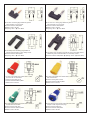
KWG-4 KWN-4
z
z
z
4mm stackable safety plug with
cage springs
Contact surface: Gold/Nickelplated
Rated current: 19A 50V
KLG-4 KLN-4
z
z
z
Length: 25.50.75.100cm
KMG-2
z
z
z
2mm plug with cage springs
Contact surface: Gold/Nickelplated
Rated current: 10A 50V
z
KLG-0.5
z
z
z
z
z
z
0.5mm plug are machined from
phosphor bronze.
2.5 p Test-Ring in parallel
Contact surface: Gold-plated
Rated current: 10A 50V
Color: Red. Black
z
z
z
z
z
z
z
Ready assembled leads wire
approx. 1M of 301/0.07mm
extra-flexible cable.
Terminated at one end by a 4mm
stackable plug and a 35mm long
crocodile clip at the other.
Contact surface: Nickel-plated.
Color: Red. Black
4mm plug with cage springs
Contact surface: Gold/Nickelplated
Rated current: 19A 50V
z
z
Length: 25.50.75.100cm
2mm stackable plug with cage
springs
Contact surface: Gold-plated
Rated current: 10A 50V
Length: 15. 30.45.60cm
KLG-0.5-2
KLG-2-4
z
z
z
z
Length: 15.30.45.60cm
CT-41
Ready assembled leads wire
approx. 0.6M of 133/0.07mm
extra-flexible cable.
Terminated at one end by a 2mm
stackable plug and a 35mm long
crocodile clip at the other.
Contact surface: Gold-plated
KLG-2
Length: 25.50.75. 100cm
Length: 15. 30.45.60cm
CT-26
4mm stackable plug with cage
springs
Contact surface: Gold/Nickelplated
Rated current: 19A 50V
KMG-4 KMN-4
Adapter lead with 0.5mm plug
and 2mm plug
Contact surface: Gold-plated
Rated current: 10A 50V
z
z
Length: 15.30.45.60cm
Adapter lead with 2mm plug and
4mm plug
Contact surface: Gold-plated
Rated current: 10A 50V
Length: 15.30.45.60cm
CT-42
LF-51
z
z
z
z
Ready assembled leads wire
approx. 1M of 301/0.07mm
extra-flexible cable.
Terminated at one end by a
4mm stackable safety plug
and a 35mm long crocodile
clip at the other.
Contact surface: Nickel-plated
Color: Red. Black
z
Fully insulated leads with
shrouded BNC plugs
complete with moulded-on strain
reliefs using RG-58 cable. Black
PVC shield. 50 [ impedance.
Length: Overall length approx.
1M
Color: Black
ΗTHE SPECIFICATONS SUBJECT TO CHANGE WITHOUT NOTCEʳ ʳ ʳ ʳ ʳ ʳ ʳ ΗTHE DRAWING IS FOR REFERENCE ONLY.