1
260N
User Guide
Rev. 002
LL
3DJH0DVWHU18VHU*XLGH
7UDGHPDUNV
7KHIROORZLQJDUHWUDGHPDUNVRUUHJLVWHUHGWUDGHPDUNVRIWKHLUUHVSHFWLYHRZQHUV2WKHUSURGXFWQDPHVPHQWLRQHGLQ
WKLVPDQXDOPD\DOVREHWUDGHPDUNVRUUHJLVWHUHGWUDGHPDUNVRIWKHLUUHVSHFWLYHRZQHUV5HJLVWHUHGWUDGHPDUNVDUH
UHJLVWHUHGLQWKH8QLWHG6WDWHV3DWHQWDQG7UDGHPDUN2IILFHVRPHWUDGHPDUNVPD\DOVREHUHJLVWHUHGLQRWKHU
FRXQWULHV3RVW6FULSWLVDWUDGHPDUNRI$GREH6\VWHPV,QFRUSRUDWHGIRUDSDJHGHVFULSWLRQODQJXDJHDQGPD\EH
UHJLVWHUHGLQFHUWDLQMXULVGLFWLRQV7KURXJKRXWWKLVPDQXDO³3RVW6FULSW/HYHO´36LVXVHGWRUHIHUWRDVHWRI
FDSDELOLWLHVGHILQHGE\$GREH6\VWHPVIRULWV3RVW6FULSW/HYHOSDJHGHVFULSWLRQODQJXDJH$GREH$GREH
3KRWR6KRS$GREH3DJH0DNHU$GREH6\VWHPV,QFRUSRUDWHG$SSOH$SSOH7DON(WKHU7DON/DVHU:ULWHU/RFDO7DON
0DFLQWRVK7UXH7\SH$SSOH&RPSXWHU,QF%DQ\DQ9,1(6%DQ\DQ'(&'(&QHW/1906'LJLWDO(TXLSPHQW
&RUSRUDWLRQ+HZOHWW3DFNDUG+33&/+3*/+38;/DVHU-HW+HZOHWW3DFNDUG&R,%03&7RNHQ5LQJ
,QWHUQDWLRQDO%XVLQHVV0DFKLQHV&RUSRUDWLRQ,QWHO,QWHO&RUSRUDWLRQ0LFURVRIW06'26:LQGRZV0LFURVRIW
&RUSRUDWLRQ1RYHOODQG1HW:DUH1RYHOO,QF7KH(1(5*<67$5ORJR8QLWHG6WDWHV(QYLURQPHQWDO3URWHFWLRQ
$JHQF\7KH(1(5*<67$5HPEOHPGRHVQRWUHSUHVHQW(3$HQGRUVHPHQWRIDQ\SURGXFWRUVHUYLFH81,;81,;
6\VWHPV/DERUDWRULHV(WKHUQHW&RUSRUDWLRQ
3URSULHWDU\6WDWHPHQW
7KHGLJLWDOO\HQFRGHGVRIWZDUHLQFOXGHGZLWK\RXU 3DJH0DVWHU1LV&RS\ULJKWHGE\&3*,QWHUQDWLRQDO
6S$$OO5LJKWV5HVHUYHG7KLVVRIWZDUHPD\QRWEHUHSURGXFHGPRGLILHGGLVSOD\HGWUDQVIHUUHGRUFRSLHGLQDQ\
IRUPRULQDQ\PDQQHURURQDQ\PHGLDLQZKROHRULQSDUWZLWKRXWWKHH[SUHVVZULWWHQSHUPLVVLRQRI&3*
,QWHUQDWLRQDO6S$
&RS\ULJKW1RWLFH
7KLVPDQXDOLV&RS\ULJKWHGE\&3*,QWHUQDWLRQDO6S$$OO5LJKWV5HVHUYHG7KLVPDQXDOPD\QRWEH
FRSLHGLQZKROHRULQSDUWQRUWUDQVIHUUHGWRDQ\RWKHUPHGLDRUODQJXDJHZLWKRXWWKHH[SUHVVZULWWHQSHUPLVVLRQRI
&3*,QWHUQDWLRQDO6S$
7KHVSHFLILFDWLRQVRI\RXUSULQWHUDQGWKHFRQWHQWRIWKLVSXEOLFDWLRQDUHVXEMHFWWRFKDQJHZLWKRXWSULRUQRWLFH
(YHU\DWWHPSWKDVEHHQPDGHWRYHULI\WKHDFFXUDF\RIWKHFRQWHQWKHUHLQ
,QWHUQHWZZZFSJLFRP
(PDLOVDOHV#FSJLFRP
◆
◆
◆
5HY
Contents
3UHIDFH
$ERXWWKLV0DQXDO
6FRSH
2YHUYLHZ
3ULQWHU2ULHQWDWLRQ
&RQYHQWLRQV
$ERXWWKH3ULQWHU
)HDWXUHV
$YDLODEOH&RQILJXUDWLRQ
&KDSWHU
*HWWLQJ6WDUWHG
6DIHW\3UHFDXWLRQV
+DQGOLQJWKH3ULQWHU
3DFNDJH&RQWHQWV
&'520&RQWHQWV
3ULQWHU/RFDWLRQ5HTXLUHPHQWV
3ULQWHU:HLJKWDQG'LPHQVLRQV
6SDFH5HTXLUHPHQWV
(QYLURQPHQW
5HY
LY
3DJH0DVWHU18VHU*XLGH
3DUWVRIWKH3ULQWHU
2SWLRQDO3ULQWHU$FFHVVRULHV
3DSHU3DWK
&KDSWHU
8VLQJWKH3ULQWHU
&RQQHFWLQJWKH3ULQWHUWRWKH$&2XWOHW
7XUQLQJ3RZHU2QDQG2II
&RQQHFWLQJWKH3ULQWHUWRWKH+RVW&RPSXWHU
3DUDOOHO3RUW
86%3RUW
6HOHFWLQJ3ULQW0HGLD
3DSHUDQG3ULQW0HGLD7R$YRLG
&RUUHFW3DSHU6WRUDJH
3ULQW0HGLD&DSDFLWLHV
3ULQW0HGLD:HLJKW7\SHDQG6L]H
/RDGLQJWKH8QLYHUVDO3DSHU7UD\
/RDGLQJWKH)URQW7UD\
&KDSWHU
8QGHUVWDQGLQJDQG1DYLJDWLQJWKH&RQWURO3DQHO
0HQXV
&RQWURO3DQHO)HDWXUHV
/&''LVSOD\
/(',QGLFDWRUV
3XVKEXWWRQV
1DYLJDWLQJWKH&RQWURO3DQHO0HQXV
0HQX6WUXFWXUH
3DSHU0HQX
,QWHUIDFH0HQX
360HQX
3&/0HQX
6\VWHP0HQX
4XDOLW\0HQX
)XQFWLRQV0HQX
6WDWXV0HQX
3DJH0DVWHU18VHU*XLGH
&KDSWHU
0DLQWDLQLQJWKH3ULQWHU
8SJUDGLQJ3ULQWHU)LUPZDUH
8SJUDGLQJ)LUPZDUH8VLQJWKH3DUDOOHO,QWHUIDFH
8SJUDGLQJ)LUPZDUH8VLQJWKH1HWZRUN,QWHUIDFH
5HSODFLQJ3ULQWHU&RPSRQHQWV
5HSODFLQJWKH7RQHU&DUWULGJH
5HSODFLQJWKH)XVHU
5HSODFLQJ)HHG5ROO1XGJHU5ROODQG5HWDUG5ROO
5HSODFLQJWKH%755ROOHU
&OHDQLQJWKH3ULQWHU
&OHDQLQJWKH([WHULRU
&OHDQLQJWKH,QWHULRU
0RYLQJWKH3ULQWHU
0RYLQJWKH3ULQWHUD6KRUW'LVWDQFH
0RYLQJWKH3ULQWHUD/RQJ'LVWDQFH
6WRULQJWKH3ULQWHUIRU/RQJ3HULRGVRI7LPH
&KDSWHU
7URXEOHVKRRWLQJ
,QVWDOODWLRQ3UREOHPV
,QRSHUDWLYH3ULQWHU
1R5HDG\0HVVDJH
1RLVH6PRNHRU6PHOO
3DSHU-DPV
&OHDULQJDQ(3DSHU-DP
&OHDULQJDQ(3DSHU-DP
&OHDULQJDQ(-DP
&OHDULQJDQ(3DSHU-DP
&OHDULQJDQ(3DSHU-DP
3ULQW,PDJH4XDOLW\3UREOHPV
2WKHU3ULQW,PDJH4XDOLW\3UREOHPV
0LVFHOODQHRXV3UREOHPV
3ULQWHULV,QRSHUDWLYH
3ULQWHU2SHUDWHV(UUDWLFDOO\
3ULQWHU0DNHV8QXVXDO1RLVHV
5RRP/LJKWV'LPRU)OLFNHU:KHQ3ULQWHU6WDUWV
3ULQWHU,QWHUIHUHVZLWK1HDUE\5DGLRRU7HOHYLVLRQ5HFHSWLRQ
:DUQLQJ0HVVDJHVDQG(UURU0HVVDJHV
:DUQLQJ0HVVDJHV
(UURU0HVVDJHV
Y
YL
3DJH0DVWHU18VHU*XLGH
&KDSWHU
8VLQJWKH'XSOH[HU
$ERXWWKH'XSOH[HU
0DMRU&RPSRQHQWVRIWKH'XSOH[HU
,QVWDOOLQJWKH'XSOH[HU
7HVWLQJWKH'XSOH[HU
6ROYLQJ'XSOH[HU3UREOHPV
,QWHUSUHWLQJ'XSOH[HU(UURU&RGHV
,QVWDOODWLRQ3UREOHPV
&OHDULQJ'XSOH[3DSHU-DPV
&RUUHFWLQJ0LVFHOODQHRXV'XSOH[HU3UREOHPV
5HPRYLQJWKH'XSOH[HU
&KDSWHU
8VLQJWKH6KHHW)HHGHU
$ERXWWKH6KHHW)HHGHU
0DMRU&RPSRQHQWVRIWKH6KHHW)HHGHU
,QVWDOOLQJWKH6KHHW3DSHU)HHGHUV
,QVWDOOLQJ2QH3DSHU)HHGHU
,QVWDOOLQJ7ZR3DSHU)HHGHUV
7HVWLQJWKH6KHHW)HHGHU
6HOHFWLQJ3ULQW0HGLD
3DSHUDQG3ULQW0HGLD7R$YRLG
&RUUHFW3DSHU6WRUDJH
3ULQW0HGLD:HLJKW7\SHDQG6L]H
/RDGLQJ3ULQW0HGLD
/RDGLQJWKH$/HWWHU/HJDO3DSHU7UD\
6ROYLQJ6KHHW)HHGHU3UREOHPV
,QWHUSUHWLQJ3DSHU)HHGHU(UURU0HVVDJHV
,QVWDOODWLRQ3UREOHPV
&OHDULQJDQ(3DSHU-DP
&RUUHFWLQJ0LVFHOODQHRXV3DSHU)HHGHU3UREOHPV
0DLQWDLQLQJWKH6KHHW)HHGHU
5HSODFLQJ)HHG5ROO1XGJHU5ROODQG5HWDUG5ROO
5HPRYLQJWKH6KHHW)HHGHU
0RYLQJWKH6KHHW)HHGHU
0RYLQJWKH3ULQWHUDQG6KHHW)HHGHUD6KRUW'LVWDQFH
0RYLQJWKH3ULQWHUDQG6KHHW)HHGHUD/RQJ'LVWDQFH
3DJH0DVWHU18VHU*XLGH
&KDSWHU
8VLQJWKH(QYHORSH)HHGHU
$ERXWWKH(QYHORSH)HHGHU
,QVWDOOLQJWKH(QYHORSH)HHGHU
,QVWDOOLQJWKH(QYHORSH)HHGHU
7HVWLQJWKH(QYHORSH)HHGHU
6HOHFWLQJ3ULQW0HGLD
3DSHUDQG3ULQW0HGLD7R$YRLG
&RUUHFW3DSHU6WRUDJH
3ULQW0HGLD:HLJKW7\SHDQG6L]H
/RDGLQJWKH(QYHORSH)HHGHU
6ROYLQJ(QYHORSH)HHGHU3UREOHPV
(QYHORSHV%HFRPH&UHDVHGZKHQ3ULQWLQJ
,QWHUSUHWLQJ(QYHORSH)HHGHU(UURU0HVVDJHV
&RUUHFWLQJ0LVFHOODQHRXV(QYHORSH)HHGHU3UREOHPV
0DLQWDLQLQJWKH(QYHORSH)HHGHU
&OHDQLQJWKH([WHULRURIWKH(QYHORSH)HHGHU
&KDSWHU
8VLQJWKH2IIVHW&DWFK7UD\
$ERXWWKH2IIVHW&DWFK7UD\
0DMRU&RPSRQHQWVRIWKH2IIVHW&DWFK7UD\
,QVWDOOLQJWKH2IIVHW&DWFK7UD\
7HVWLQJWKH2IIVHW&DWFK7UD\
6ROYLQJ2IIVHW&DWFK7UD\3UREOHPV
,QWHUSUHWLQJ2IIVHW&DWFK7UD\(UURU0HVVDJHV
,QVWDOODWLRQ3UREOHPV
&OHDULQJDQ2IIVHW&DWFK7UD\3DSHU-DP
&RUUHFWLQJ0LVFHOODQHRXV2IIVHW&DWFK7UD\3UREOHPV
0DLQWDLQLQJWKH2IIVHW&DWFK7UD\
&OHDQLQJWKH([WHULRURIWKH2IIVHW&DWFK7UD\
5HPRYLQJWKH2IIVHW&DWFK7UD\
0RYLQJWKH2IIVHW&DWFK7UD\
0RYLQJWKH2IIVHW&DWFK7UD\D6KRUW'LVWDQFH
0RYLQJWKH2IIVHW&DWFK7UD\D/RQJ'LVWDQFH
YLL
YLLL
3DJH0DVWHU18VHU*XLGH
&KDSWHU
2SWLRQDO([WHQGHG)HDWXUHV
,QVWDOOLQJ'5$00HPRU\',006
,QVWDOOLQJWKH+DUG'LVN2SWLRQ
,QVWDOOLQJWKHXVHU)/$6+',000RGXOH
8VLQJWKH+DUG'LVN2SWLRQDQG8VHU)ODVK',000RGXOH
8VLQJWKH3RZHU2Q)LOHV)HDWXUH
([WHQGHG)HDWXUHV8VLQJWKH+DUG'LVNRU8VHU)ODVK2SWLRQ
,QVWDOOLQJWKH56&566HULDO,QWHUIDFH
8VLQJWKH56&566HULDO,QWHUIDFH
8VLQJWKH&XVWRP3DSHU6L]H)HDWXUH
$SSHQGL[$
6DIHW\1RWHVDQG5HJXODWRU\&RPSOLDQFH$
6DIHW\1RWHV$
5HJXODWRU\&RPSOLDQFH$
6DIHW\&RPSOLDQFH$
(0&&RPSOLDQFH$
Preface
,QWKLV&KDSWHU ■
■
■
“Welcome” on page 2
“About this Manual” on page 2
“About the Printer” on page 4
5HY
3DJH0DVWHU18VHU*XLGH
$ERXWWKLV0DQXDO
:HOFRPH
Thank you for selecting the PageMaster 260N. This User Guide contains important information
about the operation and care of your printer. Please read this manual in its entirety and keep it at
hand for later reference.
$ERXWWKLV0DQXDO
6FRSH
This User Guide contains all of the information necessary to operate and care for your printer and
accessories. It is intended to be used with the pictorial unpacking instructions and the Installation
Guide, both included in the printer packaging. If you have not already unpacked and installed the
printer, please refer to these documents. This guide does not contain instructions for unpacking
and installing the printer.
2YHUYLHZ
This manual contains ten chapters and one appendix:
3UHIDFH
The Preface contains information about this guide and about the features and available configurations of the printer.
&KDSWHU*HWWLQJ6WDUWHG
This chapter reviews the contents of the printer packaging, explains the parts of the printer, and
describes the space and environment requirements of the printer.
&KDSWHU8VLQJWKH3ULQWHU
This chapter provides information concerning the daily use of the printer, including procedures for
connecting the printer and loading print media, and guidelines for selecting print media.
&KDSWHU8QGHUVWDQGLQJDQG1DYLJDWLQJWKH&RQWURO3DQHO
This chapter explains the control panel and its functions, and also demonstrates how to navigate
throughout the various menus and submenus that allow you to view and change the printer settings.
&KDSWHU0DLQWDLQLQJWKH3ULQWHU
This chapter provides information about maintaining your printer. Although the printer requires
very little maintenance, with normal daily use you will need to perform some routine maintenance
procedures, including replacing consumable items and cleaning the printer. This chapter also contains information about moving and storing the printer.
&KDSWHU7URXEOHVKRRWLQJ
This chapter describes the problems that you may encounter when using your printer, and provides
procedures for resolving the problems. This chapter also lists the warning and error messages that
appear on the control panel display.
&KDSWHU8VLQJWKH'XSOH[HU
This chapter provides all of the information necessary to install, use, and maintain the duplexer.
3DJH0DVWHU18VHU*XLGH $ERXWWKLV0DQXDO
&KDSWHU8VLQJWKH6KHHW)HHGHU
This chapter provides all of the information necessary to install, use, and maintain the 550-sheet
paper feeder option, including procedures for cleaning the feeder and removing paper jams.
&KDSWHU8VLQJWKH(QYHORSH)HHGHU
This chapter provides all of the information necessary to install, use, and maintain the envelope
feeder, including procedures for removing paper jams.
&KDSWHU8VLQJWKH2IIVHW&DWFK7UD\
This chapter provides all of the information necessary to install, use, and maintain the offset output
tray, including procedures for cleaning and removing paper jams.
&KDSWHU2SWLRQDO([WHQGHG)HDWXUHV
This chapter provides all of the information necessary to install and use the optional extended features: DRAMM memory DIMMs, Hard Disk, User FLASH DIMM Modules, RS-232C/RS-422
Serial Interface , the Power-On Files and the Custom Paper Size features
$SSHQGL[$6DIHW\1RWHVDQG5HJXODWRU\&RPSOLDQFHV
This appendix describes cautions to take when installing, transporting, or operating the printer, and
also includes the applicable regulatory compliances.
3ULQWHU2ULHQWDWLRQ
Throughout this guide, the four sides of the printer are referred to as front, rear, right, and left. The
front of the printer is the side near the control panel, and the rear of the printer is opposite the
front. The left and right sides of the printer are defined as the sides to the left and right, respectively, of a person who is facing the front of the printer.
&RQYHQWLRQV
This following conventions are used throughout this manual to emphasize certain procedures or
information:
127(
$QRWHLVDWLSRUH[WUDLQIRUPDWLRQWKDWPD\EHKHOSIXOLQLQVWDOOLQJRUXVLQJWKHSULQWHU
&$87,21$FDXWLRQPHVVDJHSURYLGHVLQIRUPDWLRQWKDWPD\KHOS\RXDYRLGHTXLSPHQWGDP
DJHSURFHVVIDLOXUHRULQFRQYHQLHQFH5HDGDOOFDXWLRQPHVVDJHVFDUHIXOO\
:$51,1*$ZDUQLQJPHVVDJHLQGLFDWHVWKHSRVVLELOLW\RISHUVRQDOLQMXU\LIDVSHFLILFSURFH
GXUHLVQRWSHUIRUPHGH[DFWO\DVGHVFULEHGLQWKHJXLGH3D\FORVHDWWHQWLRQWRWKHVHVHFWLRQVDQG
UHDGWKHPIXOO\WRSUHYHQWSRVVLEOHLQMXU\
3DJH0DVWHU18VHU*XLGH
$ERXWWKH3ULQWHU
$ERXWWKH3ULQWHU
The PageMaster 260N printer uses a data modulated laser beam and conventional dry-ink xerographic processes to produce images up to 1200 dpi resolution at a paper output speed of 26 pages
per minute. The printer can accommodate both plain paper and other print media, and feeds paper
from either a main 550-sheet paper tray or from the front tray, which is designed to feed special
print media such as labels and transparencies.
There are five paper handling options available for the printer, including a Duplexer for two-sided
printing, a 550-Sheet Feeder for additional paper capacity or variety, an Envelope Feeder for printing envelopes, and an Offset Catch Tray to hold and separate large print jobs.
You may connect the printer to either a local computer or a computer network system. Application
and print driver software on the computer controls image generation and print processing. The
computer sends the electronic image to the printer, where the printer turns the electronic image
into a black and white printed image.
)HDWXUHV
Your laser printer has the following features:
■
Quality printing at a high speed
The printer has an output of 26 pages per minute with a resolution up to 1200 dpi.
■
Flexible use of paper sources and delivery methods
The base configuration of the printer includes one 550-sheet universal paper feeder and a
front tray. The paper feeder can be set to any size paper from postcard to 14 inch legal. The
front tray can be set for print media from index card size to 14 inch legal, and also accommodates envelopes and labels. You may also add the following paper-handling options to the
printer: additional 550-sheet Feeders, Envelope Feeder, Duplexer, Offset Catch Tray.
■
Easy operation
The easy-to-read control panel display clearly shows the status of printer operation. Control
panel pushbuttons allow you to access and view printer menus, submenus, and status messages.
■
Single-element toner cartridge
The integrated toner cartridge contains both the toner and the photosensitive drum in a single housing, making replacement easy and convenient.
■
Continuous printing of up to 1750 sheets
The printer can print up to 1050 sheets unattended when the offset catch tray is installed,
and can print up to 1750 sheets attended when two 550-sheet feeders are installed and used
along with the front tray (100 sheets).
■
Network-readiness
The printer includes an Ethernet Network Interface Card.
3DJH0DVWHU18VHU*XLGH $ERXWWKH3ULQWHU
$YDLODEOH&RQILJXUDWLRQ
1HWZRUN&RQILJXUDWLRQ3DJH0DVWHU1
The printer is available in the following network-ready configuration:
■
■
■
■
■
■
Memory: 128 MB
Resolutions: 600 x 600 dpi, and 1200 x 1200 dpi
Paper Input: One 550-sheet universal paper tray for A4/Letter/Legal, and one 100-sheet front
tray for paper, transparencies, envelopes, and other non-standard print media
Paper Output: One 500-sheet face-down tray
Interfaces: IEEE 1284 Parallel, USB 2.0, 10/100BaseT, 10Base2
Printer Languages: PCL6e, Adobe Postscript 3
◆
◆
◆
3DJH0DVWHU18VHU*XLGH
$ERXWWKH3ULQWHU
Chapter 1
Getting Started
,QWKLV&KDSWHU ■
■
■
■
■
■
■
“About this Chapter” on page 1-2
“Safety Precautions” on page 1-3
“Package Contents” on page 1-4
“Printer Location Requirements” on page 1-5
“Parts of the Printer” on page 1-8
“Optional Printer Accessories” on page 1-11
“Paper Path” on page 1-12
5HY
3DJH0DVWHU18VHU*XLGH
$ERXWWKLV&KDSWHU
This chapter reviews the contents of the printer packaging, explains the parts of the printer, and
describes the space and environment requirements of the printer.
3DJH0DVWHU18VHU*XLGH 6DIHW\3UHFDXWLRQV
6DIHW\3UHFDXWLRQV
This printer is available in the following power specification: 220V. To prevent fire or shock hazards, connect the power plug only to a properly rated power outlet.
+DQGOLQJWKH3ULQWHU
Follow the guidelines below when lifting or moving the printer:
■
The printer is very heavy, and should always be lifted by two people. The weight of the
printer without paper tray, toner cartridge, and paper is about 51 lbs (23 kg). Never attempt
to lift the printer alone.
■
To lift the printer, have two individuals facing each other from the front and the rear of the
printer grasp the recessed areas on each side of the printer. Do not lift the printer by grasping
any area other than these recessed areas.
When lifting the printer, maintain proper lifting posture to prevent injuries.
■
3DJH0DVWHU18VHU*XLGH
3DFNDJH&RQWHQWV
3DFNDJH&RQWHQWV
Make sure that all of the items shown below are included in the printer packaging. If any items are
missing or damaged, contact your dealer.
3ULQWHUPDLQXQLW
7RQHU&DUWULGJH
;
;;
1
2
;
3
3
4
VKHHW
8QLYHUVDO
3DSHU7UD\
5
4
1
2
1
3
2
6
7
10
11
8
9
12
13
GEG-99042
3RZHU&RUG
8QSDFNLQJ,QVWUXFWLRQV
3DJH0DVWHU1
(OHFWURQLF/LEUDU\
&'520
,QVWDOODWLRQ*XLGH
5HPRWH&RQWURO
6RIWZDUH&'520
&'520&RQWHQWV
PageMaster 260N Printer Electronic Library CD-ROM
■
The PageMaster 260N Printer Electronic Library CD-ROM contains printer drivers, software, and documentation designed to help you fully utilize the printer, and also contains
Adobe PostScript fonts that match those available on the printer.
■
Remote Control Software (RCS) CD-ROM
The RCS CD-ROM contains remote control software that enables your Network/System
Administrator to manage all of your network printers from a single desktop.
3DJH0DVWHU18VHU*XLGH 3ULQWHU/RFDWLRQ5HTXLUHPHQWV
3ULQWHU/RFDWLRQ5HTXLUHPHQWV
3ULQWHU:HLJKWDQG'LPHQVLRQV
This printer weighs approximately 51 lbs (23 kg) and should always be lifted by two people. The
dimensions of the printer are listed below.
■
■
■
Printer Height: 16.3 in (413 mm)
Printer Width (left to right): 16.6 in (422 mm)
Printer Depth (front to back): 17.3 in (439 mm)
6SDFH5HTXLUHPHQWV
A certain amount of space is required for proper operation of the printer and also for performing
printer maintenance and replacing consumables. Use the following figures to plan for appropriate
clearances when determining a location for your printer.
&$87,217KHUHLVDYHQWLODWLRQRSHQLQJRQWKHOHIWVLGHRIWKHSULQWHU7RDYRLGRYHUKHDWLQJ
DQGILUHKD]DUGVEHVXUHWROHDYHDFOHDUDQFHRIDWOHDVWLQFKHVPPEHWZHHQWKLVRSHQ
LQJDQGWKHQHDUHVWZDOORURWKHUVXUIDFH
LQFKHV
PP
LQFKHV
PP
LQFKHV
PP
LQFKHV
PP
)LJXUH7RSYLHZRIWKHSULQWHU
3DJH0DVWHU18VHU*XLGH
3ULQWHU/RFDWLRQ5HTXLUHPHQWV
LQFKHV
PP
LQFKHV
PP
LQFKHV
PP
)LJXUH6LGHYLHZRIWKHSULQWHU
3DJH0DVWHU18VHU*XLGH 3ULQWHU/RFDWLRQ5HTXLUHPHQWV
(QYLURQPHQW
Use the following guidelines to determine the best location for the printer:
Horizontal, sturdy, and stable surface
Exposed to direct sunlight
Subject to vibrations
Exposed to water and high humidity
Location with good ventilation
Near heating appliances
Exposed to high levels of dust
and contamination
Exposed to magnetic fields
Location with stable temperature
and humidity
Exposed to direct air currents
Near an open flame
Subject to extreme variations in
temperature and humidity
3DJH0DVWHU18VHU*XLGH
3DUWVRIWKH3ULQWHU
3DUWVRIWKH3ULQWHU
The following figures indicate the names and functions of the main parts of the printer.
&RQWUROSDQHO
3URYLGHVDFFHVVWRDOO
FRQWUROVUHTXLUHGWR
RSHUDWHWKHSULQWHU
)URQW&RYHU
3DSHURXWSXWWUD\
3DSHUH[LWVORW
3URYLGHVDFFHVVWRWKHLQVLGHRI
WKHSULQWHUDOORZV\RXWRUHSODFH
WKHWRQHUFDUWULGJHRUUHPRYH
MDPPHGSDSHU
)URQW7UD\
3URYLGHVDQDOWHUQDWHPHWKRGRI
IHHGLQJSDSHUWRWKHSULQWHU
$FFRPPRGDWHVYDULRXVSULQW
PHGLDLQFOXGLQJHQYHORSHVWUDQV
SDUHQFLHVDQGODEHOV
7UD\([WHQVLRQ
$OORZV\RXWRORDG
ODUJHSDSHUVL]HVLQ
WKHIURQWWUD\
3RZHUVZLWFK
VKHHW8QLYHUVDO
3DSHU7UD\
3DSHUDPRXQWLQGLFDWRU
,QGLFDWHVWKHDSSUR[LPDWH
+ROGVSDSHUIURPSRVWFDUG UHPDLQLQJDPRXQWRISDSHU
VL]HWR/HJDOVL]H
)LJXUH)URQWRIWKH3ULQWHU
7RSFRYHU
5HDUFRYHU
3URYLGHVDFFHVVWRWKHUHDURIWKH
SULQWHUDOORZV\RXWRUHPRYH
MDPPHGSDSHURULQVWDOOWKH
GXSOH[HU
3URYLGHVDFFHVVWRWKHLQVLGHRIWKH
SULQWHUUHPRYLQJLWDOORZV\RXWR
LQVWDOOWKHRSWLRQDORIIVHWFDWFKWUD\
9HQWLODWLRQVORW
3RZHUFRUG
FRQQHFWRU
5HOHDVHVKRWDLUSURGXFHG
LQVLGHWKHSULQWHUWRSUHYHQW
RYHUKHDWLQJ
)LJXUH5HDURIWKH3ULQWHU
3DJH0DVWHU18VHU*XLGH 3DUWVRIWKH3ULQWHU
7RQHU&DUWULGJH
,QWHJUDWHGFDUWULGJH
FRQWDLQVWKHWRQHUDQGWKH
SKRWRVHQVLWLYHGUXP
)URQW&RYHU
3URYLGHVDFFHVVWRWKHLQWHULRU
RIWKHSULQWHU$OORZV\RXWR
UHSODFHWKHWRQHUFDUWULGJHRU
UHPRYHMDPPHGSDSHU
)LJXUH,QWHUQDO3DUWVRIWKH3ULQWHU)URQW
&$87,217KHIXVHUEHFRPHVYHU\KRWZKLOHWKHSULQWHULVRSHUDWLQJ,I\RXQHHGWRUHPRYH
WKHGUXPFDUWULGJHWRUHPRYHDSDSHUMDPWXUQWKHSRZHURIIDQGZDLWDWOHDVWPLQXWHV
EHIRUHUHPRYLQJWKHGUXPFDUWULGJHDQGWRXFKLQJWKHIXVHU
)XVHU
)L[HVWRQHURQWR
WKHSDSHU
5HDU&RYHU
3URYLGHVDFFHVVWRWKHLQWHULRU
RIWKHSULQWHU$OORZV\RXWR
LQVWDOOWKHRSWLRQDOGXSOH[HURU
UHPRYHMDPPHGSDSHU
)LJXUH,QWHUQDO3DUWVRIWKH3ULQWHU5HDU
3DJH0DVWHU18VHU*XLGH
3DUWVRIWKH3ULQWHU
/&''LVSOD\
6KRZVHUURUPHVVDJHVDQGRWKHU
VWDWXVPHVVDJHVDOVRGLVSOD\V
PHQXVVXEPHQXVDQGVHWWLQJV
/(',QGLFDWRUV
6KRZSULQWHUVWDWXV
3XVKEXWWRQV
$OORZ\RXWRQDYLJDWHWKURXJK
PHQXVSODFHDSULQWHURIIOLQHRU
FDQFHODSULQWMRE
)LJXUH&RQWURO3DQHO
3DJH0DVWHU18VHU*XLGH 2SWLRQDO3ULQWHU$FFHVVRULHV
2SWLRQDO3ULQWHU$FFHVVRULHV
The following figure shows all of the available accessories as installed on the printer:
2IIVHW&DWFK7UD\
+ROGVDQGVHSDUDWHV
ODUJHSULQWMREVE\RIIVHW
WLQJ
(QYHORSH)HHGHU
+ROGVDPD[LPXPRI
HQYHORSHVRUSRVWFDUGV
6KHHW)HHGHU
+ROGVDVKHHWSDSHUWUD\
DQGSURYLGHVH[WUDSDSHU
FDSDFLW\7KHSULQWHUFDQ
DFFRPPRGDWHWZR
DGGLWLRQDOVKHHWIHHGHUV
'XSOH[HU
(QDEOHVWZRVLGHG
SULQWLQJ
)LJXUH2SWLRQDO$FFHVVRULHV
3DJH0DVWHU18VHU*XLGH
3DSHU3DWK
3DSHU3DWK
The following figure shows the path that paper travels through the printer:
1. The paper is initially fed from the front paper tray or one of the other paper trays.
2. The image is transferred from the photosensitive drum onto the paper.
3. The fuser fixes the toner permanently on the paper.
4. After passing through the duplexer, if installed, the paper is fed once more through steps (2)
and (3).
5. The paper emerges onto the output tray, or the offset output tray if installed.
)LJXUH3DSHU3DWK
◆
◆
◆
Chapter 2
Using the Printer
,QWKLV&KDSWHU ■
■
■
■
■
■
■
“About this Chapter” on page 2-2
“Connecting the Printer to the AC Outlet” on page 2-3
“Turning Power On and Off” on page 2-4
“Connecting the Printer to the Host Computer” on page 2-5
“Selecting Print Media” on page 2-15
“Loading the Universal Paper Tray” on page 2-18
“Loading the Front Tray” on page 2-23
5HY
3DJH0DVWHU18VHU*XLGH
$ERXWWKLV&KDSWHU
This chapter provides information concerning the daily use of the printer, including procedures for
connecting the printer and loading print media, and guidelines for selecting print media.
3DJH0DVWHU18VHU*XLGH &RQQHFWLQJWKH3ULQWHUWRWKH$&2XWOHW
&RQQHFWLQJWKH3ULQWHUWRWKH$&2XWOHW
Use the following procedure to connect the power cord and turn the printer on:
Insert the power cord into the AC connector on the rear of the printer.
Verify that the power switch of the printer is in the [O] (off) position, then insert the plug of
the power cord into the AC outlet.
3DJH0DVWHU18VHU*XLGH
7XUQLQJ3RZHU2QDQG2II
7XUQLQJ3RZHU2QDQG2II
Use the following procedure to turn the printer on:
Turn the printer on by pressing [ I ] on the power switch on the left front of the printer.
The status message “Loading” appears on the display. This message indicates that the printer
is warming up and is not ready to print. After about 65 seconds, the status message changes
to “Ready”, indicating that the printer is ready to print.
/RDGLQJ
127(
5HDG\
,I DQ HUURU PHVVDJH DSSHDUV RQ WKH GLVSOD\ DIWHU \RX WXUQ WKH SULQWHU RQ UHIHU WR “Warning
Messages and Error Messages” on page 5-26
Use the following procedure to turn the printer off:
Turn the printer off by pressing the [ O ] on the power switch on the right side of the printer.
3DJH0DVWHU18VHU*XLGH &RQQHFWLQJWKH3ULQWHUWRWKH+RVW&RPSXWHU
&RQQHFWLQJWKH3ULQWHUWRWKH+RVW&RPSXWHU
You must connect the printer to your computer using an IEEE 1284 parallel cable or a USB cable.
These cables are user-supplied, the printer does not include either of these cables. The parallel and
USB ports can not be used simultaneously, and the default configuration of your printer has the
USB port turned off.
127(
:KHQ\RXWXUQWKH86%SRUWRQWKHSDUDOOHOSRUWLVDXWRPDWLFDOO\WXUQHGRII:KHQ\RXWXUQWKH
SDUDOOHOSRUWRQWKH86%SRUWLVDXWRPDWLFDOO\WXUQHGRII
3DUDOOHO3RUW
The parallel port is the default port. To connect the printer to your computer using the parallel
port, simply connect the parallel cable to the parallel port on the printer, then connect the cable to
your computer. Use the following procedure to verify that the parallel port is turned on and to
change the parallel port Interface, Format, and Mode settings:
Press the MENU button on the control panel.
Press the NEXT button until the text “Interface Menu” is shown on the second line of the
display.
Press the SELECT button to enter the interface menu.
Press the NEXT button until the text “Port” is shown on the second line of the display.
Press the SELECT button to enter the port submenu.
Press the NEXT button until the text “Parallel” is shown on the second line of the display.
Press the SELECT button to enter the parallel submenu.
Verify that the second line of the display contains the text “On”, or press the NEXT button
until the text “On” is shown on the second line of the display.
Press the SELECT button to change the parallel setting to On. After you have pressed the
SELECT button, the first line of the control panel display should contain the text “Port”,
and the second line should contain the text “Parallel”.
Press the RETURN button to return to the interface menu. The first line of the display
should contain the text “Interface Menu”, and the second line should contain the text
“Port”.
Press the NEXT button until the text “Parallel Setup” is shown on the second line of the display.
Press the SELECT button to enter the parallel setup submenu.
Press the NEXT button until the text “Interpreter” is shown on the second line of the display.
Press the SELECT button to enter the interpreter submenu.
Press the NEXT button until the desired interpreter is shown on the second line of the display. The available interpreter settings include Auto Switch, PCL, and PostScript 3.
Press the SELECT button to select the interpreter that you specified in the previous step.
After you have pressed the SELECT button, the first line of the display should contain the
text “Parallel Setup”, and the second line should contain the text “Interpreter”.
Press the NEXT button until the text “Format” is shown on the second line of the display.
3DJH0DVWHU18VHU*XLGH
&RQQHFWLQJWKH3ULQWHUWRWKH+RVW&RPSXWHU
Press the SELECT button to enter the format submenu.
Press the NEXT button until the desired format is shown on the second line of the display.
The available format settings include Raw, Normal, and Binary.
Press the SELECT button to select the format that you specified in the previous step. After
you have pressed the SELECT button, the first line of the display should contain the text
“Parallel Setup”, and the second line should contain the text “Format”.
Press the NEXT button until the text “Mode” is shown on the second line of the display.
Press the SELECT button to enter the mode submenu.
Press the NEXT button until the desired mode is shown on the second line of the display.
The available mode settings include Bidirectional and Standard.
Press the SELECT button to select the mode that you specified in the previous step. After
you have pressed the SELECT button, the first line of the display should contain the text
“Parallel Setup”, and the second line should contain the text “Mode”.
Press the RETURN button twice to return to the main menu.
Press the START/STOP button to exit the menu system.
86%3RUW
The USB port of your printer provides a reliable, high-speed, bi-directional connection between
your printer and PC. The USB standard is designed to deliver complex, graphic-rich documents to
the printer with speed and accuracy. USB-enabled printers and PCs allow up to 127 devices to be
attached to a single USB port. Fast 12Mbps communication from your PC and printer with absolute reliability.
3DJH0DVWHU18VHU*XLGH &RQQHFWLQJWKH3ULQWHUWRWKH+RVW&RPSXWHU
266XSSRUW
The USB port of your printer supports the following operating system environments:
■
Microsoft Windows 95b and 95c (also known as OSR 2.0, OSR 2.1 and OSR 2.5)
If you are using one of these operating systems, your PC may require an optional upgrade to
work properly with USB. This upgrade is called USBSUPP.EXE and is provided in the
\OTHER\USB directory of your Windows 95 CD-ROM. We do not supply this update. To
find out if your hardware/operating system combination supports USB, run the free program
USBREADY.EXE, available from www.usb.org.
■
Microsoft Windows 98 and 98se, ME, 2000, and XP
These operating systems come with complete support for USB. You should still run
USBREADY.EXE from www.usb.org to ensure that the required software and hardware are
installed.
■
Apple Mac OS 8.6 and above
This version of Apple's operating system ships with the USB equipped systems and contains
the necessary code to support USB. No additional software or hardware should be required.
3DJH0DVWHU18VHU*XLGH
&RQQHFWLQJWKH3ULQWHUWRWKH+RVW&RPSXWHU
+DUGZDUH6XSSRUW
The USB port of your printer supports the following hardware:
■
Intel
Most recent Intel systems will contain the needed components. However, there are a number
of older systems that, while having USB hardware, have an obsolete USB implementation.
Your USB printer will not work with these older systems unless a separate USB controller
card is installed in your system. It is possible to have working hardware but not have a physical port, in which case the proper connector must be purchased from the system supplier.
127(
■
6\VWHPV PDGH LQ DQG HDUOLHU SUREDEO\ GR QRW VXSSRUW 86% FRUUHFWO\ RQ WKH PRWKHUERDUG
V\VWHPV PDGH LQ PD\ RU PD\ QRW SURSHUO\ VXSSRUW 86% DQG V\VWHPV PDGH VLQFH SUREDEO\GRVXSSRUW86%FRUUHFWO\
Apple
The Apple iMac and G3/G4 systems come with working USB hardware and fully support
your USB printer. Older PCI-based Macintosh systems may be upgraded with a USB card.
This configuration should work with the correct version of the operating system.
3DJH0DVWHU18VHU*XLGH &RQQHFWLQJWKH3ULQWHUWRWKH+RVW&RPSXWHU
,QVWDOODWLRQIRU:LQGRZV
Use the following procedure to install USB for Windows:
Verify that your system supports USB and has an available USB connector. If you do not have
an available connector, you may need to purchase a USB hub.
127(
<RXPD\XVHDQXQSRZHUHG86%KXEVLQFHWKHSULQWHULVFRQVLGHUHGDVHOISRZHUHGGHYLFHDQGZLOO
QRWGUDZSRZHUIURPWKH86%SRUW
Power on the host system and the printer and allow the two systems to finish booting.
Attach the USB cable to both the printer and the host. It does not matter which host connector you attach the cable to; however, make sure you always attach it to the same connector.
127(
7KH86%SULQWHUSRUWFUHDWHGLVDVVRFLDWHGZLWKWKHDFWXDOSRUWWRZKLFKWKHGHYLFHLVDWWDFKHG,IWKH
SULQWHULVDWWDFKHGWRDGLIIHUHQWKDUGZDUHSRUWDQHZ86%SULQWHUSRUWZLOOEHFUHDWHGHYHQWKRXJK
LWLVDWWDFKHGWRWKHVDPHSULQWHU
7KH PD[LPXP OHQJWK RI D 86% FDEOH LV IHHW PHWHUV /RQJHU GLVWDQFHV PD\ EH VSDQQHG LI
LQWHUYHQLQJKXEVDUHXVHG7KHUHLVDOLPLWRIKXEVEHWZHHQWKHKRVWDQGDQ\JLYHQGHYLFHJLYLQJ
DPD[LPXPGLVWDQFHRIIHHWPHWHUV
Windows displays a dialog box stating that new hardware has been found and Windows is
searching for a driver.
Browse to the location of the USB port software and select the appropriate version for either
Windows 95 or Windows 98 (\Software\USB\Win95 or \Software\USB\Win98 on your
CD-ROM or the location where you expanded the driver files).
Windows creates a GNUSBn printer port.
3DJH0DVWHU18VHU*XLGH
&RQQHFWLQJWKH3ULQWHUWRWKH+RVW&RPSXWHU
At this point, you may install the printer normally, either by using the "Add Printer" wizard
or by running the appropriate setup program, or your system may announce that "New
Hardware has been found". In either case, install the driver required for your printer at this
time.
After the printer has been installed, make sure that it prints to the GNUSBn port.
Ensure that the Spooler settings for the printer have "Disable bi-directional support for this
printer" checked.
Your USB printer is now ready to print.
3DJH0DVWHU18VHU*XLGH &RQQHFWLQJWKH3ULQWHUWRWKH+RVW&RPSXWHU
,QVWDOODWLRQIRU0DF26
Power on the printer and the host computer.
Ensure that the "Apple LaserWriter Software" is installed.
Attach the USB cable to the host and the printer. Note that the printer is considered a "self
powered" device and as such may be plugged into any available USB port on the Macintosh,
including the one on the keyboard .
Open the "Desktop Printer Utility" (installed when you installed the Apple Laser Writer Software).
Choose the correct driver to use, depending on the printer you are installing.
Choose "Printer (USB)" and press "OK".
Choose the PPD file that corresponds to your printer.
Choose the correct printer.
Press "Create".
You now have a desktop shortcut to the USB printer and are ready to print.
3DJH0DVWHU18VHU*XLGH
&RQQHFWLQJWKH3ULQWHUWRWKH+RVW&RPSXWHU
8VLQJWKH86%3RUW
If you would like to use the USB port instead of the parallel port, use the following procedure to
turn the USB port on and change the USB interface and format settings on the printer:
Press the MENU button on the control panel.
Press the NEXT button until the text “Interface Menu” is shown on the second line of the
display.
Press the SELECT button to enter the interface menu.
Press the NEXT button until the text “Port” is shown on the second line of the display.
Press the SELECT button to enter the port submenu.
Press the NEXT button until the text “USB” is shown on the second line of the display.
Press the SELECT button to enter the USB submenu.
Press the NEXT button until the text “On” is shown on the second line of the display.
Press the SELECT button to change the USB setting to On. After you have pressed the
SELECT button, the first line of the control panel display should contain the text “Port”,
and the second line should contain the text “USB”.
3DJH0DVWHU18VHU*XLGH &RQQHFWLQJWKH3ULQWHUWRWKH+RVW&RPSXWHU
Press the RETURN button to return to the interface menu. The first line of the display
should contain the text “Interface Menu”, and the second line should contain the text
“Port”.
Press the NEXT button until the text “USB Setup” is shown on the second line of the display.
Press the SELECT button to enter the USB setup submenu.
Press the NEXT button until the text “Interpreter” is shown on the second line of the display.
Press the SELECT button to enter the interpreter submenu.
Press the NEXT button until the desired interpreter is shown on the second line of the display. The available interpreter settings include Auto Switch, PCL, and PostScript 3.
Press the SELECT button to select the interpreter that you chose in the previous step. After
you have pressed the SELECT button, the first line of the display should contain the text
“USB Setup”, and the second line should contain the text “Interpreter”.
Press the NEXT button until the text “Format” is shown on the second line of the display.
Press the SELECT button to enter the format submenu.
Press the NEXT button until the desired format is shown on the second line of the display.
The available format settings include Raw, Normal, and Binary.
Press the SELECT button to select the format setting that you specified in the previous step.
After you have pressed the SELECT button, the first line of the display should contain the
text “USB Setup”, and the second line should contain the text “Format”.
Press the RETURN button twice to return to the main menu.
Press the START/STOP button to exit the menu system.
3DJH0DVWHU18VHU*XLGH
&RQQHFWLQJWKH3ULQWHUWRWKH+RVW&RPSXWHU
86%5HVRXUFHV
If you would like more information about USB, refer to the www.usb.org website. This organization is responsible for the determining the USB standard and has a number of FAQ's available that
should answer most questions.
3DJH0DVWHU18VHU*XLGH 6HOHFWLQJ3ULQW0HGLD
6HOHFWLQJ3ULQW0HGLD
Your printer can print on a variety of media, including plain paper, labels, transparencies, and envelopes. Always use print media that meet the guidelines for use with this printer. Print media that is
not recommended for use with this printer may cause frequent paper jams or poor print quality.
3DSHUDQG3ULQW0HGLD7R$YRLG
Do not use paper or print media that has any of the following characteristics:
■
■
■
■
■
■
■
■
■
■
■
■
■
■
■
Does not meet the paper and media size and weight specifications for this printer
Is not labeled for use with xerographic printers or xerographic copiers
Cannot withstand temperatures of up to 310°F/155°C
Is in a sealed package that is obviously damaged or wet
Is excessively wrinkled, curled, torn, or warped
Is folded or creased
Has either an extremely slick surface or an extremely textured surface
Has an exposed adhesive surface
Has paper pieces glued or taped to the media
Has staples or paper clips attached
Is categorized as thermal paper, coated paper, or carbon paper
Is an envelope that is embossed, is made of extremely thick paper, or is padded
Is an envelope that has metal clasps
Is an envelope with gummed or adhesive surfaces
Is a sheet of labels that has the backing sheet exposed between individual labels
&RUUHFW3DSHU6WRUDJH
It is important to store paper correctly prior to placing it in the printer, since improper storage can
cause frequent paper jams and poor print quality. Use the following guidelines when storing paper
for use in the printer:
■
■
■
■
■
Store reams of paper on a flat surface, and always store them stacked horizontally.
Store reams of paper in an area away from both direct sunlight and high humidity
Open sealed reams only when you are ready to load the paper into the paper tray, and always
close and seal partial reams of paper.
Do not stack partial reams of paper.
Store paper in a dry area, with a temperature of 10 to 30 degrees Celsius and relative humidity of 30% to 60%.
3ULQW0HGLD&DSDFLWLHV
Your printer can hold up to 1750 sheets of standard weight paper, depending upon the options
installed. The printer can be configured in the following three variations:
■
■
■
Printer (550 sheets)
Printer with 550 sheet feeder(1100 sheets)
Printer with two 550 sheet feeders (1650 sheets)
3DJH0DVWHU18VHU*XLGH
6HOHFWLQJ3ULQW0HGLD
The following table shows the five configurations and the breakdown of paper capacity:
)URQW7UD\
VWDQGDUG
7UD\
VWDQGDUG
7UD\
RSWLRQ
7UD\
RSWLRQ
7RWDO3DSHU
&DSDFLW\
If you want to use paper that is an odd size or weight, you must use the front paper tray. The front
tray can hold the following quantities of non-standard print media:
■
■
■
■
■
■
Envelopes : 10
Transparencies: 30
Labels: 30
Standard Paper: 100
Other paper: Stack Height 11.5mm
Standard Postcard: 30
127(
8VHLQ)URQW7UD\
'RQRWXVH
)XOO\FRYHUHGZLWKODEHOV
6KLQ\EDFNLQJVKHHWH[SRVHG
([SHFWDVOLJKWUHGXFWLRQLQLPDJHTXDOLW\ZKHQ\RXSULQWRQHQYHORSHVODEHOVWUDQVSDUHQFLHVRU
SRVWFDUGV
3DJH0DVWHU18VHU*XLGH 6HOHFWLQJ3ULQW0HGLD
3ULQW0HGLD:HLJKW7\SHDQG6L]H
The following table defines print media that you can use in each of the paper sources, and also indicates the feed orientation—long edge feed (LEF) or short edge feed (SEF). If you have concerns
about a specific brand or type of media, try samples of the media to determine if the resulting
printer performance and print quality meet your expectations.
3DSHU6RXUFH
0HWHU:HLJKW
3DSHU7\SHDQG)HHG
'LUHFWLRQ
8QLYHUVDO3DSHU7UD\
PDLQWUD\DQGRSWLRQDO
VKHHWSDSHUIHHGHU
WRJP
$Q\SDSHU
'RQRWXVHODEHOVWRFN
RURWKHUVSHFLDOPHGLD
LQWKHVKHHWSDSHU
WUD\
)URQW7UD\
WRJP
3DSHU6L]HV
$FFRPPRGDWHG
:LGWK
PPWRPP
WRLQFKHV
/HQJWK
PPWRPP
WRLQFKHV
$6()
[PP
[LQFKHV
/HWWHU6()
[PP
[LQFKHV
/HJDOLQFK
[PP
[LQFKHV
/HJDOLQFK
[PP
[LQFKHV
([HFXWLYH6()
[PP
[LQFKHV
$6()
[PP
[LQFKHV
%6()
[PP
[LQFKHV
(QYHORSHV
7UDQVSDUHQFLHV
/DEHOV
3RVWFDUGV
6WDQGDUG3DSHU/()
DQG6()
2WKHU3DSHU
:LGWK
WRLQFKHV
PPWRPP
/HQJWK
WRLQFKHV
PPWRPP
3DJH0DVWHU18VHU*XLGH
/RDGLQJWKH8QLYHUVDO3DSHU7UD\
/RDGLQJWKH8QLYHUVDO3DSHU7UD\
The 550-sheet universal paper tray has two width guides that are located on the sides of the tray,
and one length guide that is located near the center of the tray. These guides allow you to adjust the
size of the area that holds paper.
127(
7KHIROORZLQJSURFHGXUHVKRZV\RXKRZWRORDGSDSHULQWRWKHPDLQSDSHUWUD\7RORDGSDSHULQWR
WKHRSWLRQDOVKHHWSDSHUIHHGHUVLPSO\FRPSOHWHWKHSURFHGXUHXVLQJWKHVKHHWSDSHUWUD\
DQGIHHGHUUDWKHUWKDQWKHPDLQSDSHUWUD\
Use the following procedure to load paper into the 550 sheet universal paper tray:
Place the paper tray on a level surface.
Squeeze the length guide, lift it up, and slide it to the rear of the tray.
3DJH0DVWHU18VHU*XLGH
/RDGLQJWKH8QLYHUVDO3DSHU7UD\
If the paper you are using is longer than A4 (297 cm), press the square green button on the
bottom of the paper tray to release the rear of the tray, and pull the tray out to extend it.
Squeeze the right width guide, lift it up, and slide the guides to the sides of the tray.
3DJH0DVWHU18VHU*XLGH
/RDGLQJWKH8QLYHUVDO3DSHU7UD\
Verify that the plate has dropped down into the base of the paper tray. If the tray is locked in
the up potision, pull the lever near the front of the tray to release the plate, or push the paper
tray all the way into the printer and then remove it.
&$87,21'RQRWRYHUORDGWKHWUD\DQGPDNHVXUHWKHSDSHUVWDFNLVEHQHDWKWKHUHWDLQLQJ
FOLSVRQERWKVLGHVRIWKHWUD\)DQSDSHUEHIRUHSODFLQJLWLQWKHWUD\DQGSODFHSDSHULQWKHWUD\
ZLWKWKHSULQWVLGHXS
Align the edges of the paper and place it in the center of the paper tray with the side to print
on facing down.
127(
7R DYRLG SDSHU MDPV DQG RWKHU SDSHU WUDQVSRUWDWLRQ SUREOHPV PDNH VXUH WKH OHQJWK DQG ZLGWK
JXLGHVDUHDGMXVWHGWRPDWFKWKHSDSHUVL]HDQGDUHORFNHGILUPO\LQWRSODFH
3DJH0DVWHU18VHU*XLGH
/RDGLQJWKH8QLYHUVDO3DSHU7UD\
Squeeze the right width guide, lift it up, and adjust the guides to match the paper width.
Squeeze the length guide, lift it up, and adjust the guide to match the paper length.
Grasp the paper tray with both hands and insert it into the paper tray well on the printer.
3DJH0DVWHU18VHU*XLGH
/RDGLQJWKH8QLYHUVDO3DSHU7UD\
Push the paper tray completely into the printer, making sure the tray is properly seated.
Use the paper level indicator on the front right of the printer to determine when the paper
supply is low.
3DJH0DVWHU18VHU*XLGH
/RDGLQJWKH)URQW7UD\
/RDGLQJWKH)URQW7UD\
The front tray located on the front of the printer can accommodate a maximum of 100 sheets of
paper, and can also accommodate a maximum of 30 sheets of standard labels, transparencies, or
postcards, and a maximum of 10 standard envelopes. The tray has two guides that are located on
the left and right sides of the tray. These guides allow you to adjust the size of the area that holds the
print media. Use the following guidelines when loading the front tray:
Do not mix print media in the front tray; for example, do not load a stack that includes both
envelopes and standard paper. Load only one type of print media.
Do not mix print media sizes in the front tray; for example, do not load a stack that includes
■
two or more different sizes of paper.
Do not load print media that is obviously damaged, wet, creased, or wrinkled.
■
Do not overfill the front tray.
■
Use the following procedure to load paper in the front tray:
■
Open the front tray by pulling the hand grip on the top of the front tray cover.
If you are using paper that is letter size or larger, pull out the input tray extension.
3DJH0DVWHU18VHU*XLGH
/RDGLQJWKH)URQW7UD\
Slide the paper guides so they match the size of the paper that you are loading.
Stack the paper that you will load in the front tray, making sure that the edges are aligned and
neat. Position the paper stack so the surface to be printed faces up.
Load the stack of paper into the front tray by sliding the stack between the paper guides and
then pushing the paper stack into the tray until it will not go any further.
Check the paper stack to make sure it is not loaded at an angle and that the guides barely
touch the stack.
&$87,21'RQRWSUHVVWKHJXLGHVWLJKWO\DJDLQVWWKHVWDFNWKHJXLGHVVKRXOGMXVWEDUHO\
WRXFKWKHVWDFNRISDSHU3DSHUJXLGHVWKDWDUHWRRWLJKWFDQFDXVHIHHGMDPV
◆
◆
◆
Chapter 3
Understanding and
Navigating the Control Panel
Menus
,QWKLV&KDSWHU ■
■
■
■
■
■
■
■
■
■
■
■
“About this Chapter” on page 3-2
“Control Panel Features” on page 3-2
“Navigating the Control Panel Menus” on page 3-4
“Menu Structure” on page 3-6
“Paper Menu” on page 3-8
“Interface Menu” on page 3-10
“PS Menu” on page 3-13
“PCL Menu” on page 3-14
“System Menu” on page 3-17
“Quality Menu” on page 3-19
“Functions Menu” on page 3-20
“Status Menu” on page 3-21
5HY
3DJH0DVWHU18VHU*XLGH
&RQWURO3DQHO)HDWXUHV
$ERXWWKLV&KDSWHU
This chapter explains the control panel and its functions, and also demonstrates how to navigate
throughout the various menus and submenus that allow you to view and change the printer settings.
&RQWURO3DQHO)HDWXUHV
The control panel is located on the front of the printer, and contains the display, indicators, and
pushbuttons that allow you to view and change the printer settings.
The figure below shows the control panel features.
/&''LVSOD\
/(',QGLFDWRUV
3XVKEXWWRQV
)LJXUH&RQWURO3DQHO
/&''LVSOD\
The LCD display shows status and error messages that inform you of the current status of the
printer, and also displays menus, submenus, and printer settings when you are in the menu system.
The display contains two lines of text, each with a maximum of sixteen characters.
3DJH0DVWHU18VHU*XLGH &RQWURO3DQHO)HDWXUHV
/(',QGLFDWRUV
The LED indicators also indicate printer status. The four indicators can each be on, off, or blinking, indicating different phases of printer operation. The table below explains the LED indicators.
/('
&RORU
:KHQ2II
:KHQ2Q
:KHQ%OLQNLQJ
*UHHQ
3ULQWHULV127
5($'<
3ULQWHULV5($'<
1$
*UHHQ
3ULQWHULV,'/(
3ULQWHULV$&7,9(
SURFHVVLQJDMRE
3ULQWHULV:$,7,1*DSDUWLDOMRE
KDVEHHQSULQWHGDQGWKHSULQWHU
LVZDLWLQJIRUDGGLWLRQDOMREGDWD
*UHHQ
32:(5LVRII
32:(5LVRQ
3RZHU6DYHU0RGH21
<HOORZ
3ULQWHULVQRWLQ
HUURUPRGH
7KHUHLVDQHUURUWKDWUHTXLUHV
XVHULQWHUYHQWLRQVXFKDVD
SDSHUMDPDVHUYLFHFDOO
UHTXLUHGHWF
1$
3XVKEXWWRQV
The control panel pushbuttons allow you to access and navigate menus, and also assist you in recovering from printer errors. The table below explains the functions of the eight pushbuttons.
3XVKEXWWRQ
)XQFWLRQ
67$576723²3XVKWKLVEXWWRQWRVWDUWRUVWRSWKHSULQWHURUWRH[LWWKHPHQX
V\VWHP
0(18²3XVKWKLVEXWWRQWRHQWHUWKHPHQXV\VWHP
1(;7²3XVKWKLVEXWWRQWRPRYHWRWKHQH[WPHQXVXEPHQXRUVHWWLQJZLWKLQ
WKHVDPHOHYHORIWKHPHQXVWUXFWXUH
6(/(&7²3XVKWKLVEXWWRQWRVHOHFWWKHPHQXRUVXEPHQXWKDWLVVKRZQRQWKH
VHFRQGOLQHRIWKHGLVSOD\RUWRFKRRVHDQGVDYHWKHVHWWLQJVKRZQRQWKHVHFRQG
OLQHRIWKHGLVSOD\
&$1&(/²3XVKWKLVEXWWRQWRFDQFHODQDFWLRQ
3DJH0DVWHU18VHU*XLGH
1DYLJDWLQJWKH&RQWURO3DQHO0HQXV
3XVKEXWWRQ
)XQFWLRQ
67$786²3XVKWKLVEXWWRQWRHQWHUWKH6WDWXV0HQXDQGYLHZWKHFXUUHQWVWDWXV
RISULQWHU
35(9,286²3XVKWKLVEXWWRQWRUHWXUQWRWKHSUHYLRXVPHQXVXEPHQXRURSWLRQ
ZLWKLQWKHVDPHOHYHORIWKHPHQXVWUXFWXUH
5(7851²3XVKWKLVEXWWRQWRPRYHXSRQHOHYHOLQWKHPHQXVWUXFWXUHWRWKH
PHQXVKRZQRQWKHILUVWOLQHRIWKHGLVSOD\
1DYLJDWLQJWKH&RQWURO3DQHO0HQXV
When you press the MENU button on the control panel, you enter the printer’s menu system. At
that point, the first line of the display contains the text “Menu”, indicating that you are in the
menu system. The second line of the display lists the active menu, which you can change by pressing the NEXT or PREVIOUS button.
0HQX
3DSHU0HQX
If you press the NEXT button repeatedly, the second line of the display cycles through the main
menus in the following order:
■
■
■
■
■
■
■
Paper Menu
Interface Menu
PS Menu
PCL Menu
System Menu
Quality Menu
Functions
3DJH0DVWHU18VHU*XLGH 1DYLJDWLQJWKH&RQWURO3DQHO0HQXV
127(
$GGLWLRQDO PHQXV DQG VXEPHQXV PD\ DSSHDU LQ WKH SULQWHU PHQX V\VWHP ZKHQ RWKHU RSWLRQV DUH
LQVWDOOHG
The following figure shows the sequence of pushbuttons and display messages that would allow you
to change the number of copies printed. This example illustrates the basic relationship between
menus and submenus and demonstrates how the NEXT, PREVIOUS, SELECT, and RETURN
buttons help you to navigate through the menus.
0HQX
3DSHU0HQX
0HQX
,QWHUIDFH0HQX
0HQX
3DSHU0HQX
&RSLHV
&RSLHV
3DSHU0HQX
&RSLHV
&RSLHV
3DSHU0HQX
&RSLHV
0HQX
3DSHU0HQX
)LJXUH1DYLJDWLQJWKH3DSHU0HQX
1. Press the MENU button on the control panel.
2. Press the NEXT button until the text “Paper Menu” is shown on the second line of the display.
3. Press the SELECT button to enter the paper menu.
4. Press the NEXT button until the text “Copies” is shown on the second line of the display.
5. Press the SELECT button to enter the copies submenu.
6. Press the NEXT or PREVIOUS button to increase or decrease the number of copies printed.
7. Press the SELECT button to save this setting.
8. Press the START/STOP button to exit the menu system.
3DJH0DVWHU18VHU*XLGH
0HQX6WUXFWXUH
0HQX6WUXFWXUH
The following figure shows the structure of the control panel main menus and submenus. .
3DSHU0HQX
&RSLHV
'HIDXOW6RXUFH
0DQXDO)HHG
2XWSXW7UD\
0HGLD6L]H7\SH
)URQW7UD\
7UD\
7UD\RSWLRQDO
7UD\RSWLRQDO
%ODQN3DJHV
)URQW7UD\)LUVW
$XWR5HVL]H
&XVWRP6L]H8QLW
,QWHUIDFH0HQX
3RUW
3DUDOOHO
1HWZRUN&DUG
86%
360HQX
3ULQW36(UURUV
0DQXDO)HHG72
3DUDOOHO6HWXS
,QWHUSUHWHU
)RUPDW
0RGH
'HOD\2XW&ORVH
%LQDU\36
1HWZRUN6HWXS
,QWHUSUHWHU
)RUPDW
1HWZRUN$GGUHVV
,3$GGUHVV
6XEQHW0DVN
'HIDXOW5RXWHU
/3'%DQQHU
'+&3
'HOD\2XW&ORVH
+RVW1DPH
P'16
/RFDO/LQN
P'16+RVW1DPH
P'166YF1DPH
0XOWL6HVVLRQ
%LQDU\36
3&/0HQX
2ULHQWDWLRQ
)RQW6RXUFH
)RQW1XPEHU
3LWFK
6\PERO6HW
0DFUR)LOWHU
/LQHV3HU3DJH
&50RGH
/)0RGH
))0RGH
3ULQW$UHD
3DUDPHWHU9DOXHV
3DSHU6RXUFH
3DSHU6L]H
86%6HWXS
,QWHUSUHWHU
)RUPDW
'HOD\2XW&ORVH
%LQDU\36
6\VWHP0HQX
)DFWRU\'HIDXOWV
'LVSOD\/DQJXDJH
3RZHU6DYHU
:DLW7LPHRXW
-RE7LPHRXW
-DP5HFRYHU\
+H[3ULQW
3DJH&RPSUHVVLRQ
'WDVWUHDP0DVWHU
4XDOLW\0HQX
5HVROXWLRQ
7RQHU6DYHU
3ULQW'HQVLW\
)XQFWLRQV
5HVHW3ULQWHU
3ULQW6XPPDU\
3ULQW7HVW
3ULQW)RQWV
)LJXUH3ULQWHU0HQX6WUXFWXUH
127(
3OHDVHFRQVXOW\RXU&3*,QWHUQDWLRQDO7HFKQLFDO6XSSRUWSHUVRQIRULQIRUPDWLRQRQXVHRIWKLV
IHDWXUH
3DJH0DVWHU18VHU*XLGH 0HQX6WUXFWXUH
127(
$GGLWLRQDO PHQXV DQG VXEPHQXV PD\ DSSHDU LQ WKH SULQWHU PHQX V\VWHP ZKHQ RWKHU RSWLRQV DUH
LQVWDOOHG
6WDWXV0HQX
In addition to the main menus listed above, the printer also provides a status menu that allows you
to view the current printer settings for the input and output trays and the toner cartridge.
6WDWXV
)URQW7UD\
0HGLD6L]H
0HGLD7\SH
/HYHO
7UD\
0HGLD6L]H
0HGLD7\SH
/HYHO
7UD\RSWLRQDO
0HGLD6L]H
0HGLD7\SH
/HYHO
7UD\RSWLRQDO
0HGLD6L]H
0HGLD7\SH
/HYHO
)DFH'RZQ7UD\
7RQHU
3DJH0DVWHU18VHU*XLGH
3DSHU0HQX
3DSHU0HQX
The Paper Menu provides access to the printer settings for various paper-handling functions. Use
the following procedure to enter the paper menu:
1. Press the MENU button on the control panel.
2. Press the NEXT button until the text “Paper Menu” is shown on the second line of the display.
3. Press the SELECT button to enter the Paper Menu.
4. Press the NEXT button to move through the submenus: Copies, Default Source, Manual
Feed, Output Tray, Media Size/Type, Blank Pages, Front Tray First , Auto Resize and Custom Size Unit.
5. Use the procedures in the following table to access and change the printer paper-handling settings:
6XEPHQXV
'HIDXOW6HWWLQJ
$YDLODEOH6HWWLQJV
3URFHGXUHIRU&KDQJLQJ6HWWLQJ
&RSLHV
7KLVVXEPHQXDOORZV
\RXWRFKDQJHWKH
QXPEHURIFRSLHV
SULQWHG
1XPEHUV
3UHVV1(;7RU35(9,286WR
LQFUHDVHRUGHFUHDVHWKHQXPEHURI
FRSLHVSULQWHG
3UHVV6(/(&7WRVDYHWKLVVHWWLQJ
'HIDXOW6RXUFH
7KLVVXEPHQXDOORZV
\RXWRFKRRVHDGHIDXOW
SDSHUVRXUFHIURPDOLVW
RIDOOLQVWDOOHGVRXUFHV
7UD\
)URQW
7UD\
7UD\RSWLRQDO
7UD\RSWLRQDO
3UHVV1(;7RU35(9,286WRVFUROO
WKURXJKWKHOLVWRIDYDLODEOHVRXUFHVRI
SDSHU
3UHVV6(/(&7WRVHWDVRXUFHDVWKH
GHIDXOW
0DQXDO)HHG
7KLVVXEPHQXDOORZV
\RXWRWXUQWKHPDQXDO
IHHGRQRURII
2II
2Q
2II
3UHVV1(;7RU35(9,286WRWRJJOH
EHWZHHQ21DQG2))
3UHVV6(/(&7WRVDYHWKLVVHWWLQJ
2XWSXW7UD\
7KLVVXEPHQXDOORZV
\RXWRFKRRVHDGHIDXOW
RXWSXWWUD\IURPDOLVW
RIDOOLQVWDOOHGRXWSXW
WUD\V
)DFH'RZQ7UD\
)DFH'RZQ7UD\
2IIVHW7UD\RSWLRQDO
3UHVV1(;7RU35(9,286WRVFUROO
WKURXJKWKHOLVWRIDYDLODEOHRXWSXW
WUD\V
3UHVV6(/(&7WRVHWDWUD\DVWKH
GHIDXOW
3DJH0DVWHU18VHU*XLGH 3DSHU0HQX
6XEPHQXV
'HIDXOW6HWWLQJ
$YDLODEOH6HWWLQJV
3URFHGXUHIRU&KDQJLQJ6HWWLQJ
0HGLD6L]H7\SH
7KLVVXEPHQXDOORZV
\RXWRVHWWKHPHGLD
VL]HDQGW\SHIRUWKH
)URQW7UD\DQGVHWWKH
PHGLDOW\SHIRUDOORWKHU
WUD\V
)URQW7UD\
6L]H$
7\SH3ODLQ
&XVWRP6L]H
Width: 209
mm
Length: 39
mm
6L]H
)URQW7UD\
/HWWHU$
%$
6WDWHPHQW
([HFXWLYH
&(QYHORSH
'/
(QYHORSH
&RP
(QYHORSH
0RQDUFK
(QYHORSH
/HJDO)ROLR
$
3UHVV1(;7RU35(9,286WRVFUROO
WKURXJKWKHOLVWRIDYDLODEOHVRXUFHVRI
SDSHU
3UHVV6(/(&7WRFKRRVHDWUD\
3UHVV1(;7RU35(9,286WRWRJJOH
EHWZHHQ0(',$6,=(0(',$
7<3(DQG&867206,=(
3UHVV6(/(&7WRFKRRVHHLWKHU
3UHVV1(;7RU35(9,286WRVFUROO
WKURXJKWKHDYDLODEOHVL]HVRUW\SHV
3UHVV6(/(&7WRVHWDVL]HRUW\SH
7UD\
7\SH3ODLQ
&XVWRP6L]H
Width: 209
mm
Length: 39
mm
8VH&XVWRP
3DSHURII
7UD\RSWLRQDO
7\SH3ODLQ
7UD\RSWLRQDO
7\SH3ODLQ
7\SH
)URQW7UD\
3ODLQ
7UDQVSDUHQF\
3UHSXQFKHG
/HWWHUKHDG
&RORUHG
3UHSULQWHG
%RQG/DEHO
&DUG6WRFN
3RVWFDUG
(QYHORSH
2WKHU
2WKHU7UD\V
3ODLQ
7UDQVSDUHQF\
3UHSXQFKHG
/HWWHUKHDG
&RORUHG
3UHSULQWHG
%RQG2WKHU
%ODQN3DJHV
7KLVVXEPHQXDOORZV
\RXWRFKRRVHWRHLWKHU
SULQWRUQRWSULQWEODQN
SDJHVRIDGRFXPHQW
3ULQW
3ULQW
'R1RW3ULQW
3UHVV1(;7RU35(9,286WRWRJJOH
EHWZHHQ35,17DQG'212735,17
3UHVV6(/(&7WRVDYHWKLVVHWWLQJ
)URQW7UD\)LUVW
7KLVVXEPHQXVHWVWKH
IURQWWUD\DVWKHGHIDXOW
SDSHUVRXUFHLISDSHU
VL]HDQGW\SHDUHWKH
VDPHDVIURQWWUD\
2II
2Q
2II
3UHVV1(;7RU35(9,286WRWRJJOH
EHWZHHQ21DQG2))
3UHVV6(/(&7WRVDYHWKLVVHWWLQJ
$XWR5HVL]H
7KLVVXEPHQXDOORZV
\RXWRVHWWKHSULQWHUWR
DXWRPDWLFDOO\FRQWLQXH
WKHSULQWMREZKHQWKHUH
LVDPHGLDVL]H
PLVPDWFK3RVW6FULSW
SULQWMREVZLOOVFDOHWR
WKHQHDUHVWSDSHUVL]H
3&/ZLOOQRWVFDOHEXW
ZLOOSULQWRQWKHQHDUHVW
SDSHUVL]H
2II
2Q
2II
3UHVV1(;7RU35(9,286WRWRJJOH
EHWZHHQ21DQG2))
3UHVV6(/(&7WRVDYHWKLVVHWWLQJ
&XVWRP6L]H8QLW
0LOOLPLWHUV
0LOOLPLWHUV
,QFKHV
3UHVV1(;7RU35(9,286WRVHOHFW
PLOOLPLWHUVRULQFKHV
3UHVV6(/(&7WRVDYHWKLVVHWWLQJ
7KLVVXEPHQXDOORZV
\RXWRVHWWKHXQLWRI
PHDVXUHPHQWIRUWKH
FXVWRPSDSHUVL]H
3DJH0DVWHU18VHU*XLGH
,QWHUIDFH0HQX
,QWHUIDFH0HQX
The Interface Menu provides access to the printer interface settings. Use the following procedure to
enter the interface menu:
1. Press the MENU button on the control panel.
2. Press the NEXT button until the text “Interface Menu” is shown on the second line of the
display.
3. Press the SELECT button to enter the interface menu.
4. Press the NEXT button to move through the submenus: Port, Parallel Setup, Network 1
Setup and USB Setup.
5. Use the procedures in the following table to access and change the printer interface settings:
6XEPHQXV
'HIDXOW
6HWWLQJ
$YDLODEOH
6HWWLQJV
3URFHGXUHIRU&KDQJLQJ6HWWLQJ
3RUW
7KLVVXEPHQXDOORZV\RX
WRFKRRVHWKHW\SHRI
LQWHUIDFH
3DUDOOHO
2Q
3DUDOOHO
2Q2II
1HWZRUN
&DUG
2Q
1HWZRUN&DUG
2Q2II
3UHVV1(;7RU35(9,286WRVFUROOWKURXJK
3$5$//(/1(7:25.&$5'DQG86%
3UHVV6(/(&7WRVDYHWKLVVHWWLQJ
86%
2Q
86%
2Q2II
,QWHUSUHWHU
$XWR6ZLWFK
,QWHUSUHWHU
$XWR6ZLWFK
3&/
3RVW6FULSW
)RUPDW
5DZ
)RUPDW
5DZ
1RUPDO
%LQDU\
0RGH
%LGLUHFWLRQDO
0RGH
%LGLUHFWLRQDO
6WDQGDUG
'HOD\2XW
&ORVH
2II
'HOD\2XW&ORVH
2Q
2II
%LQDU\36
2II
%LQDU\36
2Q
2II
3DUDOOHO6HWXS
7KLVVXEPHQXDOORZV\RX
WRVHWXSWKHSDUDOOHO
LQWHUIDFH
3UHVV1(;7RU35(9,286WRVFUROOWKURXJK
,17(535(7(5)250$702'('(/$<
287&/26(DQG%,1$5<36VXEPHQXV
3UHVV6(/(&7WRFKRRVHDVXEPHQX
3UHVV1(;7RU35(9,286WRVFUROOWKURXJK
WKHVHWWLQJV
3UHVV6(/(&7WRFKRRVHDQGVDYHDVHWWLQJ
3DJH0DVWHU18VHU*XLGH
,QWHUIDFH0HQX
6XEPHQXV
'HIDXOW
6HWWLQJ
$YDLODEOH
6HWWLQJV
3URFHGXUHIRU&KDQJLQJ6HWWLQJ
1HWZRUN6HWXS
7KLVVXEPHQXDOORZV\RX
WRVHWXSWKH1HWZRUN
LQWHUIDFH
,QWHUSUHWHU
$XWR6ZLWFK
,QWHUSUHWHU
$XWR6ZLWFK
3&/
3RVW6FULSW
)RUPDW
5DZ
)RUPDW
1RUPDO
%LQDU\
5DZ
3UHVV1(;7RU35(9,286WRPRYHDPRQJWKH
VXEPHQXV
3UHVV6(/(&7WRFKRRVHDVXEPHQX
3UHVV1(;7RU35(9,286WRVFUROOWKURXJK
WKHVHWWLQJV
3UHVV6(/(&7WRVDYHWKLVVHWWLQJ
1HWZRUN
$GGUHVV
;;;;;;
1HWZRUN$GGUHVV
;;;;;;
,3$GGUHVV
,3$GGUHVV
6XEQHW0DVN
6XEQHW0DVN
XVHUVSHFLILHG
XVHUVSHFLILHG
'HIDXOW
5RXWHU
'HIDXOW5RXWHU
/'3%DQQHU
2II
/'3%DQQHU
2II
2Q
'+&3
2II
'+&3
2II
2Q
'HOD\2XW
&ORVH
2II
'HOD\2XW&ORVH
2II
2Q
+RVW1DPH
+RVW1DPH
PRGHOQDPH;;
;;;
PRGHOQDPH;;;;;
P'16
2Q
P'16
2Q
2II
/RFDO/LQN
/RFDO/LQN
;;;;;;;;
;;;;
;;;;;;;;;;;
;
P'16+RVW
1DPH
P'16+RVW1DPH
XVHUVSHFLILHG
XVHUVSHFLILHG
XVHUVSHFLILHG
XVHUVSHFLILHG
PRGHOQDPH;;
;;;
PRGHOQDPH;;;;;
3DJH0DVWHU18VHU*XLGH
,QWHUIDFH0HQX
6XEPHQXV
'HIDXOW
6HWWLQJ
$YDLODEOH
6HWWLQJV
P'166YF
1DPH
P'166YF1DPH
0XOWL6HVVLRQ
2Q
0XOWL6HVVLRQ
2Q
2II
%LQDU\36
2II
%LQDU\36
2Q
2II
,QWHUSUHWHU
$XWR6ZLWFK
,QWHUSUHWHU
$XWR6ZLWFK
3&/
3RVW6FULSW
)RUPDW
5DZ
)RUPDW
5DZ
1RUPDO
%LQDU\
'HOD\2XW
&ORVH
2II
'HOD\2XW&ORVH
2II
2Q
%LQDU\36
2II
%LQDU\36
2Q
2II
3URFHGXUHIRU&KDQJLQJ6HWWLQJ
PRGHOQDPH;;;;;
PRGHOQDPH;;
;;;
86%6HWXS
7KLVVXEPHQXDOORZV\RX
WRFKRRVHVHWXSWKH86%
LQWHUIDFH
3UHVV1(;7RU35(9,286WRVFUROOWKURXJK
WKH,17(535(7(5)250$7'(/$<287
&/26(DQG%,1$5<36VXEPHQXV
3UHVV6(/(&7WRFKRRVHDVXEPHQX
3UHVV1(;7RU35(9,286WRVFUROOWKURXJK
WKHVHWWLQJV
3UHVV6(/(&7WRFKRRVHDQGVDYHDVHWWLQJ
3DJH0DVWHU18VHU*XLGH
360HQX
360HQX
The PS Menu provides access to the PostScript settings. Use the following procedure to enter the
PS Menu:
1. Press the MENU button on the control panel.
2. Press the NEXT button until the text “PS Menu” is shown on the second line of the display.
3. Press the SELECT button to enter the PS menu.
4. Press the NEXT button to move through the submenus: Print PS Errors and Manual Feed
TO.
5. Press the SELECT button to enter a submenu.
6. Use the procedures in the following table to access and change the PostScript settings:
6XEPHQXV
'HIDXOW
6HWWLQJ
$YDLODEOH6HWWLQJV
3URFHGXUHIRU&KDQJLQJ6HWWLQJV
3ULQW36(UURUV
7KLVVXEPHQXDOORZV\RX
WRFKRRVHWRHLWKHUSULQWRU
QRWSULQW36HUURUV
2II
2Q
2II
3UHVV1(;7RU35(9,286WRWRJJOHEHWZHHQ21
SULQWDQG2))GRQRWSULQW
3UHVV6(/(&7WRVDYHWKLVVHWWLQJ
0DQXDO)HHG72
7KLVVXEPHQXDOORZV\RX
WRVHWWKHPDQXDOIHHG
WLPHRXW²WKHQXPEHURI
VHFRQGVWKHSULQWHUVKRXOG
ZDLWIRUDPDQXDOIHHG$
VHWWLQJRIZLOOFDXVH
SULQWHUWRZDLWLQGHILQLWHO\
IRUDPDQXDOIHHG
3UHVV1(;7RU35(9,286WRLQFUHDVHRU
GHFUHDVHHDFKGLJLWRIWKHILYHGLJLWQXPEHU
3UHVV6(/(&7WRPRYHWRWKHQH[WQXPEHU
3UHVV6(/(&7DIWHUVHWWLQJWKHODVWGLJLWWRVDYH
WKHVHWWLQJ
3DJH0DVWHU18VHU*XLGH
3&/0HQX
3&/0HQX
The PCL Menu provides access to the PCL settings. Use the following procedure to enter the PCL
menu:
1. Press the MENU button on the control panel.
2. Press the NEXT button until the text “PCL Menu” is shown on the second line of the display.
3. Press the SELECT button to enter the PCL menu.
4. Press the NEXT button to move through the submenus: Orientation, Font Source, Font
Number, Pitch, Symbol Set, Macro Filter, Lines Per Page, CR Mode, LF Mode, FF Mode,
Print Area and Parameter Values.
5. Press the SELECT button to enter a submenu.
6. Use the procedures in the following table to access and change the PCL settings:
6XEPHQXV
'HIDXOW6HWWLQJ
$YDLODEOH6HWWLQJV
3URFHGXUHIRU&KDQJLQJ6HWWLQJ
2ULHQWDWLRQ
7KLVVXEPHQXDOORZV
\RXWRFKRRVHWKH
RULHQWDWLRQRIWKH
SDJH
3RUWUDLW
3RUWUDLW
/DQGVFDSH
3UHVV1(;7RU35(9,286WR
WRJJOHEHWZHHQ32575$,7DQG
/$1'6&$3(
3UHVV6(/(&7WRFKRRVHDQG
VDYHDQRULHQWDWLRQ
)RQW6RXUFH
7KLVVXEPHQXDOORZV
\RXWRFKRRVHDIRQW
VRXUFH
,QWHUQDO
,QWHUQDO
3UHVV1(;7RU35(9,286WR
VFUROOWKURXJKWKHDYDLODEOHIRQW
VRXUFHV
3UHVV6(/(&7WRFKRRVHDQGVHW
DVRXUFH
)RQW1XPEHU
7KLVVXEPHQXDOORZV
\RXWRVHWWKHIRQW
QXPEHU
1XPEHUV
3UHVV1(;7RU35(9,286WR
LQFUHDVHRUGHFUHDVHWKHIRQW
QXPEHU
3UHVV6(/(&7WRVDYHWKLV
VHWWLQJ
3LWFK
7KLVVXEPHQXDOORZV
\RXWRFKDQJHWKH
SLWFKRIWH[W
3UHVV1(;7RU35(9,286WR
LQFUHDVHRUGHFUHDVHWKHSLWFK
3UHVV6(/(&7WRVDYHWKLV
VHWWLQJ
3DJH0DVWHU18VHU*XLGH
3&/0HQX
6XEPHQXV
'HIDXOW6HWWLQJ
$YDLODEOH6HWWLQJV
3URFHGXUHIRU&KDQJLQJ6HWWLQJ
6\PERO6HW
7KLVVXEPHQXDOORZV
\RXWRFKRRVHD
V\PEROVHW
83&&3
83&&3
83&'1
83&
83&
73&7XUNLVK
8:,1/DWLQ
(:,1/DWLQ
7:,1/DWLQ
-'HVN7RS
-367H[W
-9HQWXUD,QWO
-9HQWXUD86
-0LFURVRIW3XE
00DWK
360DWK
09HQWXUD0DWK
0DFUR)LOWHU
7KLVVXEPHQXDOORZV
\RXWRWXUQWKHPDFUR
ILOWHURQRURII
2II
2Q
2II
3UHVV1(;7RU35(9,286WR
WRJJOHEHWZHHQ21DQG2))
3UHVV6(/(&7WRVDYHWKLV
VHWWLQJ
/LQHV3HU3DJH
7KLVVXEPHQXDOORZV
\RXWRFKDQJHWKH
QXPEHURIOLQHVSHU
SDJH
3UHVV1(;7RU35(9,286WR
LQFUHDVHRUGHFUHDVHWKHOLQHVSHU
SDJH
3UHVV6(/(&7WRVDYHWKLV
VHWWLQJ
&50RGH
7KLVVXEPHQXDOORZV
\RXWRSGHILQHWKH
DFWLRQSURPSWHGE\D
FDUULDJHUHWXUQ²D
FDUULDJHUHWXUQHTXDOV
HLWKHUDFDULDJH
UHWXUQDORQHRUD
FDUULDJHUHWXUQDQGD
OLQHIHHGWRJHWKHU
&5 &5
&5 &5
&5 &5/)
3UHVV1(;7RU35(9,286WR
FKRRVHIURP&5 &5RU
&5 &5/)
3UHVV6(/(&7WRVDYHWKLV
VHWWLQJ
/)0RGH
7KLVVXEPHQXDOORZV
\RXWRGHILQHWKH
DFWLRQSURPSWHGE\D
OLQHIHHG²DOLQHIHHG
HTXDOVHLWKHUDOLQH
IHHGDORQHRUD
FDUULDJHUHWXUQDQGD
OLQHIHHGWRJHWKHU
/) /)
/) /)
/) &5/)
3UHVV1(;7RU35(9,286WR
FKRRVHIURP/) /)RU
/) &5/)
3UHVV6(/(&7WRVDYHWKLV
VHWWLQJ
83L)RQW
8/HJDO
(,628.
8,62$6&,,
8,626ZHGLVK
,,62,WDOLDQ
6,626SDQLVK
*,62*HUPDQ
',621RUZHJ
),62)UHQFK
8:,1/DWLQ
85RPDQ
1,62
1,62
1,62
3UHVV1(;7RU35(9,286WR
VFUROOWKURXJKWKHDYDLODEOH
V\PEROVHWV
3UHVV6(/(&7WRFKRRVHDQGVHW
DV\PEROVHW
3DJH0DVWHU18VHU*XLGH
3&/0HQX
6XEPHQXV
'HIDXOW6HWWLQJ
$YDLODEOH6HWWLQJV
3URFHGXUHIRU&KDQJLQJ6HWWLQJ
))0RGH
7KLVVXEPHQXDOORZV
\RXWRGHILQHWKH
DFWLRQSURPSWHGE\D
IRUPIHHG²DIRUP
IHHGHTXDOVHLWKHUD
IRUPIHHGDORQHRUD
FDUULDJHUHWXUQDQGD
IRUPIHHGWRJHWKHU
)) ))
)) ))
)) &5))
3UHVV1(;7RU35(9,286WR
FKRRVHIURP)) ))RU
)) &5))
3UHVV6(/(&7WRVDYHWKLV
VHWWLQJ
3ULQW$UHD
7KLVVXEPHQXDOORZV
\RXWRH[SDQGWKH
SULQWDUHD
1RUPDO
1RUPDO
([SDQGHG
3UHVV1(;7RU35(9,286WR
WRJJOHEHWZHHQ1RUPDODQG
([SDQGHG
3UHVV6(/(&7WRVDYHWKLV
VHWWLQJ
3DUDPHWHU9DOXHV
7KLVVXEPHQXDOORZV
\RXWRVSHFLIL\ZKLFK
3&/HVFDSHVHTXHQFH
SDUDPHWHUYDOXHV
VKRXOGEHDVVRFLDWHG
ZLWKHDFKVSHFLILF
VHOHFWLRQ
3DSHU6RXUFH
)URQW7UD\
3DSHU6RXUFH
)URQW7UD\
7UD\
7UD\
RSWLRQDO
WUD\
7UD\
RSWLRQDO
WUD\
$XWR6HOHFW
3DSHU6L]H
([HFXWLYH
3DSHU6L]H
([HFXWLYH /HWWHU /HJDO 6WDWHPHQW )ROLR $ $ $ % 0RQDUFK(QYHORSH
&RP(QYHORSH
'/(QYHORSH
&(QYHORSH
3UHVV1(;7RU35(9,286WR
LQFUHDVHRUGHFUHDVHHDFKGLJLWRI
WKHILYHGLJLWQXPEHU
3UHVV6(/(&7WRPRYHWRWKH
QH[WQXPEHU
3UHVV6(/(&7DIWHUVHWWLQJWKH
ODVWGLJLWWRVDYHWKHVHWWLQJ
3DJH0DVWHU18VHU*XLGH
6\VWHP0HQX
6\VWHP0HQX
The system menu provides access to system settings. Use the following procedure to enter the system menu:
1. Press the MENU button on the control panel.
2. Press the NEXT button until the text “System Menu” is shown on the second line of the display.
3. Press the SELECT button to enter the system menu.
4. Press the NEXT button to move through the submenus: Factory Defaults, Display Language, Power Saver, Wait Timeout, Job Timeout, Jam Recovery, Hex Print, Page Compression, and DatastreamMaster.
5. Press the SELECT button to enter a submenu.
6. Use the procedures in the following table to access and change the system settings:
6XEPHQXV
'HIDXOW6HWWLQJ
$YDLODEOH6HWWLQJV
3URFHGXUHIRU&KDQJLQJ6HWWLQJ
)DFWRU\'HIDXOWV
7KLVVXEPHQXDOORZV\RXWRUHVHWWKH
SULQWHUWR86RU1RQ86IDFWRU\
GHIDXOWV
86
86
1RQ86
3UHVV1(;7RU35(9,286WR
WRJJOHVEHWZHHQ86DQG12186
3UHVV6(/(&7WRFKRRVHDQGVHWWKH
IDFWRU\GHIDXOWV
'LVSOD\/DQJXDJH
7KLVVXEPHQXDOORZV\RXWRFKDQJH
WKHODQJXDJHRIWKHGLVSOD\PHVVDJHV
(QJOLVK
(QJOLVK
)UDQFDLV
'HXWVFK
,WDOLDQR
(VSDQRO
3UHVV1(;7RU35(9,286WRVFUROO
WKURXJKWKHDYDLODEOHODQJXDJHV
(QJOLVK)UHQFK)UDQFDLV*HUPDQ
'HXWVFK,WDOLDQ,WDOLDQRRU
6SDQLVK(VSDQRO
3UHVV6(/(&7WRFKRRVHDQGVHWWKH
ODQJXDJH
3RZHU6DYHU
7KLVVXEPHQXDOORZV\RXWRVHWWKH
QXPEHURIPLQXWHVWKHSULQWHULVLGOH
EHIRUHLWUHYHUWVWR3RZHU6DYHU
0RGH
3UHVV1(;7RU35(9,286WR
LQFUHDVHRUGHFUHDVHWKHQXPEHURI
PLQXWHV
3UHVV6(/(&7WRVDYHWKLVVHWWLQJ
:DLW7LPHRXW
7KLVVXEPHQXDOORZV\RXWRLQFUHDVH
RUGHFUHDVHWKHOHQJWKRIWLPHLQ
VHFRQGVWKDWWKHSULQWHUZLOOUHPDLQ
LQWKHZDLWLQJVWDWH²DMRELVEHLQJ
SURFHVVHGQRHQGRIILOHKDVEHHQ
GHWHFWHGDQGWKHUHLVQRPRUHGDWDWR
SURFHVV7KLVVHWWLQJDSSOLHVWRERWK
3&/DQG3RVW6FULSWSULQWMREV
3UHVV1(;7RU35(9,286WR
LQFUHDVHRUGHFUHDVHHDFKGLJLWRIWKH
ILYHGLJLWQXPEHU
3UHVV6(/(&7VHWRQHGLJLWDQG
PRYHWRWKHQH[WGLJLW
3UHVV6(/(&7DIWHUFKDQJLQJWKHODVW
GLJLWWRVDYHWKLVVHWWLQJ
-RE7LPHRXW
7KLVVXEPHQXDOORZV\RXWRLQFUHDVH
RUGHFUHDVHWKHWLPHOLPLWLQ
VHFRQGVIRU3RVW6FULSWMREV$
VHWWLQJLQGLFDWHVQRWLPHRXW7KLV
VHWWLQJDSSOLHVRQO\WR3RVW6FULSW
MREV
3UHVV1(;7RU35(9,286WR
LQFUHDVHRUGHFUHDVHHDFKGLJLWRIWKH
ILYHGLJLWQXPEHU
3UHVV6(/(&7VHWRQHGLJLWDQG
PRYHWRWKHQH[WGLJLW
3UHVV6(/(&7DIWHUFKDQJLQJWKHODVW
GLJLWWRVDYHWKLVVHWWLQJ
3DJH0DVWHU18VHU*XLGH
6\VWHP0HQX
6XEPHQXV
'HIDXOW6HWWLQJ
$YDLODEOH6HWWLQJV
3URFHGXUHIRU&KDQJLQJ6HWWLQJ
-DP5HFRYHU\
7KLVVXEPHQXDOORZV\RXWRWXUQMDP
UHFRYHU\RQRURII
2Q
2Q
2II
3UHVV1(;7RU35(9,286WRWRJJOH
EHWZHHQ21DQG2))
3UHVV6(/(&7WRVDYHWKLVVHWWLQJ
+H[3ULQW
7KLVVXEPHQXDOORZV\RXWRSULQW
KH[DGHFLPDOFKDUDFWHUV
2II
2Q
2II
3UHVV1(;7RU35(9,286WRWRJJOH
EHWZHHQ21DQG2))
3UHVV6(/(&7WRVDYHWKLVVHWWLQJ
3DJH&RPSUHVVLRQ
7KLVVXEPHQXDOORZV\RXWRWXUQ
SDJHFRPSUHVVLRQRQRURII
2II
2Q
2II
3UHVV1(;7RU35(9,286WRWRJJOH
EHWZHHQ21DQG2))
3UHVV6(/(&7WRVDYHWKLVVHWWLQJ
'DWDVWUHDP0DVWHU
7KLVVXEPHQXDOORZVWRWXUQWKLV
IHDWXUHRQRURII
2Q
2Q
2II
3UHVV1(;7RU35(9,286WRWRJJOH
EHWZHHQ21DQG2))
3UHVV6(/(&7WRVDYHWKLVVHWWLQJ
1RWH3OHDVHFRQVXOW\RXU&3*
,QWHUQDWLRQDO7HFKQLFDO6XSSRUW
SHUVRQIRULQIRUPDWLRQRQXVHRIWKLV
IHDWXUH
3DJH0DVWHU18VHU*XLGH
4XDOLW\0HQX
4XDOLW\0HQX
The Quality Menu provides access to the printer settings that are related to print quality. Use the
following procedure to enter the Quality Menu:
1. Press the MENU button on the control panel.
2. Press the NEXT button until the text “Quality Menu” is shown on the second line of the display.
3. Press the SELECT button to enter the system menu.
4. Press the NEXT button to move through the submenus: Resolution, Toner Saver and Print
Density.
5. Press the SELECT button to enter a submenu.
6. Use the procedures in the following table to access and change the system settings:
6XEPHQXV
'HIDXOW6HWWLQJ
$YDLODEOH6HWWLQJV
3URFHGXUHIRU&KDQJLQJ6HWWLQJ
5HVROXWLRQ
7KLVVXEPHQXDOORZV\RXWRVHWWKH
UHVROXWLRQGSL
GSL
GSL
GSL
3UHVV1(;7RU35(9,286WRWRJJOH
EHWZHHQWKHDYDLODEOHUHVROXWLRQV
3UHVV6(/(&7WRFKRRVHDQGVHWWKH
GSL
7RQHU6DYHU
7KLVVXEPHQXDOORZV\RXWR
FKRRVHIURPVHYHUDOWRQHUVDYLQJ
VHWWLQJV
2II
2II2Q
3UHVV1(;7RU35(9,286WRVFUROO
WKURXJKWKHDYDLODEOHWRQHUVHWWLQJV
3UHVV6(/(&7WRFKRRVHDQGVDYHWKLV
VHWWLQJ
3ULQW'HQVLW\
7KLVVXEPHQXDOORZV\RXWR
VSHFLI\WKHSULQWGHQVLW\
UHSUHVHQWVWKHOLJKWHVWSULQW
GHQVLW\ZKLOHUHSUHVHQWVWKH
GDUNHVWSULQWGHQVLW\
3UHVV1(;7RU35(9,286WRVFUROO
WKURXJKWKHDYDLODEOHSULQWGHQVLW\
VHWWLQJV
3UHVV6(/(&7WRFKRRVHDQGVDYHWKLV
VHWWLQJ
3DJH0DVWHU18VHU*XLGH
)XQFWLRQV0HQX
)XQFWLRQV0HQX
The Functions Menu provides access to several printer functions that can supply you with information about the printer and its settings. Use the following procedure to enter the Functions Menu:
1. Press the MENU button on the control panel.
2. Press the NEXT button until the text “Functions” is shown on the second line of the display.
3. Press the SELECT button to enter the system menu.
4. Press the NEXT button to move through the available functions: Reset Printer, Print Summary, Print Test and Print Fonts.
5. Use the procedures in the following table to execute the functions:
)XQFWLRQV
3URFHGXUHIRU([HFXWLQJ)XQFWLRQ
5HVHW3ULQWHU
7KLVIXQFWLRQUHVHWVWKHSULQWHU
3UHVV6(/(&7WRUHVHWWKHSULQWHU
3ULQW6XPPDU\
7KLVIXQFWLRQSULQWVDOLVWRIDOOSULQWHU
VHWWLQJV
3UHVV6(/(&7WRSULQWDVXPPDU\RIWKHSULQWHUVHWWLQJV
3ULQW7HVW
7KLVIXQFWLRQDOORZV\RXWRSULQWDVLQJOHWHVW
SDJHRUDFRQWLQXRXVWHVWSDJH
3UHVV1(;7RU35(9,286WRWRJJOHEHWZHHQ
6,1*/(3$*(DQG&217,18286
3UHVV6(/(&7WRSULQWWKHWHVWSDJHV
3ULQW)RQWV
7KLVIXQFWLRQDOORZV\RXWRSULQW3RVWVFULSWRU
3&/IRQWOLVWV
3UHVV1(;7RU35(9,286WRWRJJOHEHWZHHQ
32676&5,37DQG3&/
3UHVV6(/(&7WRVHOHFWDQGSULQWWKHVSHFLILFIRQWV
OLVW
3DJH0DVWHU18VHU*XLGH
6WDWXV0HQX
6WDWXV0HQX
In addition to the main menus listed above, the printer also provides a status menu that allows you
to view the current settings for the input and output trays and the toner cartridge. Use the following procedure to enter the Status Menu:
1. Press the STATUS button on the control panel.
2. Press the NEXT button to move through the submenus: Front, Tray 1, Tray 2 (optional),
Tray 3 (optional), Face Down Tray and Toner.
3. Press the SELECT button to enter a submenu.
4. Use the procedures in the following table to view the status of the printer:
6XEPHQX
3URFHGXUHIRU([HFXWLQJ)XQFWLRQ
)URQW7UD\
7KLVVXEPHQXDOORZV\RXWRYLHZ
WKHFXUUHQW0HGLD6L]HDQG0HGLD
7\SHDQG/HYHOIRUWKHIURQWWUD\
3UHVV1(;7RU35(9,286WRVFUROOWKURXJKWKHPHGLD
VL]HPHGLDW\SHDQGOHYHOVHWWLQJVIRUWKH)URQW7UD\
3UHVV6(/(&7WRYLHZDVSHFLILFVHWWLQJ
7UD\
7KLVVXEPHQXDOORZV\RXWRYLHZ
WKHFXUUHQW0HGLD6L]H0HGLD
7\SHDQG/HYHOIRU7UD\
3UHVV1(;7RU35(9,286WRVFUROOWKURXJKWKHPHGLD
VL]HPHGLDW\SHDQGOHYHOVHWWLQJVIRU7UD\
3UHVV6(/(&7WRYLHZDVSHFLILFVHWWLQJ
7UD\
7KLVVXEPHQXDOORZV\RXWRYLHZ
WKHFXUUHQW0HGLD6L]H0HGLD
7\SHDQG/HYHOIRU7UD\
RSWLRQDO
3UHVV1(;7RU35(9,286WRVFUROOWKURXJKWKHPHGLD
VL]HPHGLDW\SHDQGOHYHOVHWWLQJVIRU7UD\
3UHVV6(/(&7WRYLHZDVSHFLILFVHWWLQJ
7UD\
7KLVVXEPHQXDOORZV\RXWRYLHZ
WKHFXUUHQW0HGLD6L]H0HGLD
7\SHDQG/HYHOIRU7UD\
RSWLRQDO
3UHVV1(;7RU35(9,286WRVFUROOWKURXJKWKHPHGLD
VL]HPHGLDW\SHDQGOHYHOVHWWLQJVIRU7UD\
3UHVV6(/(&7WRYLHZDVSHFLILFVHWWLQJ
)DFH'RZQ7UD\
7KLVVXEPHQXDOORZV\RXWRYLHZ
WKHVWDWXVRIWKHIDFHGRZQWUD\
3UHVV6(/(&7WRYLHZWKHVWDWXVRIWKH)DFH'RZQ7UD\
7RQHU
3UHVV6(/(&7WRYLHZWKHVWDWXVRIWKHWRQHUFDUWULGJH
◆
◆
◆
3DJH0DVWHU18VHU*XLGH
6WDWXV0HQX
Chapter 4
Maintaining the Printer
In this Chapter . . .
■
■
■
■
■
■
“About this Chapter” on page 4-2
“Upgrading Printer Firmware” on page 4-2
“Replacing Printer Components” on page 4-3
“Cleaning the Printer” on page 4-18
“Moving the Printer” on page 4-20
“Storing the Printer for Long Periods of Time” on page 4-21
Rev. 002
4-2
PageMaster 260N User Guide
Upgrading Printer Firmware
About this Chapter
This chapter provides information about maintaining your printer. Although the printer requires
very little maintenance, with normal daily use you will need to perform some routine maintenance
procedures, including replacing consumable items and cleaning the printer. This chapter also contains information about moving and storing the printer.
Upgrading Printer Firmware
The executable firmware for the printer controller is stored in FLASH memory. You can easily
upgrade this firmware on site when a new version of code is available. The upgrade process involves
sending the new code, which is usually named with a .LOD extension, to the printer using either
the parallel or network interface. When the printer receives the file, it will automatically recognize it
as a firmware upgrade file and will program it into the FLASH memory. During this process the
printer will display information about each sub-file that it is receiving or programming. When finished, the printer displays the text “Upgrade Completed” and reboots, executing the new firmware.
Contact your dealer or service provider for more information about firmware upgrades.
Upgrading Firmware Using the Parallel Interface
To upgrade the printer using the parallel interface, go to the DOS prompt and use the copy command to copy the new file to the printer. For example, type “copy newversion.lod/b lpt1” at the
DOS prompt, where “newversion” is the name of the firmware upgrade file and “lpt1” is the printer
you would like to upgrade. Be sure to use the “/b” switch on the copy command line to ensure that
the data is sent in binary mode.
NOTE:
If you are using a PC that is not running Windows or if you do not have any printer drivers installed
and configured to use the parallel interface, you will need to configure the parallel port for
permanent retry by entering the following command PRIOR to entering the copy command
discussed above: mode lpt1:,,p
If you are running Windows, you may get an error message during the upgrade process that
indicates that the printer is busy or that there is a printer error. This message box will contain
check-boxes for “Retry” or “Cancel”. DO NOT SELECT CANCEL. This error message is only a
result of the printer programming a large file into FLASH memory and will disappear once the
programming is completed.
Upgrading Firmware Using the Network Interface
To upgrade printer firmware using the network interface, simply send the new file to the printer
using whatever procedure you normally use to send a print file. This procedure varies depending on
the network environment.
PageMaster 260N User Guide
Replacing Printer Components
4-3
Replacing Printer Components
Replacing the Toner Cartridge
The toner cartridge contains the dry ink as well as the xerographic drum and associated components that create the xerographic image on a sheet of paper. The toner cartridge will eventually run
out of ink through normal use. When the toner is low, printed images will be uneven or very light.
Use the following guidelines when using or storing a toner cartridge:
■
■
■
■
■
■
■
An unopened and correctly stored toner cartridge has a shelf life of approximately two years.
Do not open the box containing the toner cartridge until you are ready to install the cartridge
into the printer.
Store the toner cartridge box horizontally—not on end.
Keep the cartridge out of the reach of children, and in an area where the temperature remains
between 32°F and 95°F and the humidity remains between 15% to 85%. If you bring a cold
toner cartridge into a warm room, wait a least an hour for the temperature to stabilize before
opening the cartridge box.
Do not disassemble the toner cartridge.
Toner is a safe material, but if you get any on your hands DO NOT wash them in hot water.
Use only cold water to wash off toner. Hot water sets the toner and makes it difficult to
remove.
A shutter protects the photosensitive drum from ambient light. Do not open the drum shutter by hand.
Drum Shutter
CAUTION: Do not expose the new toner cartridge to strong light for more than a few minutes
before installing it into the printer.
WARNING! Do not dispose of used toner cartridges in an incinerator or in an open fire.
4-4
PageMaster 260N User Guide
Replacing Printer Components
Use the following procedure to replace the toner cartridge:
1. Place a drop-cloth or some paper on the table or floor near the printer.
2. Press the button on the top of the printer to open the front cover, and pull the cover all the
way open.
3. Remove the old toner cartridge from the printer and carefully place it on the drop-cloth.
4. Remove the new toner cartridge from its packaging.
5. Rock the toner cartridge back and forth and then shake it horizontally to ensure that the
toner is evenly distributed.
PageMaster 260N User Guide
Replacing Printer Components
4-5
6. Grasp the toner cartridge firmly and pull the sealing tape straight out from the cartridge.
7. Slide the pegs on the toner cartridge into the channels on the inside of the printer, and lower
the toner cartridge into the printer.
8. Close the front cover.
4-6
PageMaster 260N User Guide
Replacing Printer Components
Disposing of the Print Cartridge
1. Place the used toner cartridge inside the new toner cartridge box and seal the box.
2. Dispose of or recycle the used toner cartridge.
WARNING! Do not dispose of the old toner cartridge in an incinerator or in an open fire.
Replacing the Fuser
The fuser melts the toner image into the paper to form a finished print. The fuser wears with normal use and can leave dirt or marks on printed sheets when worn. The normal life of a fuser is
approximately 200,000 A4/Letter size prints at 5% area coverage. Running high image density
prints or large format paper will cause the fuser life to be shorter.
WARNING! The fuser becomes very hot during operation. Do not touch the fuser until it is
cool.
NOTE:
In the following procedure, the left and right sides of the printer are those to the left and right of a
person facing the rear of the printer.
NOTE:
If you are using the duplexer, refer to ”Chapter
duplexer before attempting to replace the fuser.
6 Using the Duplexer” and remove the
Use the following procedure to remove and replace the fuser:
1. Turn the printer off by pressing the [ O ] on the power switch on the front of the printer, and
disconnect the AC power cord from the wall outlet. Wait at least 30 minutes before proceeding to remove the fuser.
PageMaster 260N User Guide
Replacing Printer Components
4-7
2. Squeeze the tabs on the top of the rear cover, and pull the cover toward you to open it.
3. Remove the screws that secure the fuser to the printer.
4. Grasp the metal brackets on the sides of the fuser and pull the fuser toward you to remove it
from the printer.
5. Remove the new fuser from its packaging, and remove any shipping tape or spacers.
4-8
PageMaster 260N User Guide
Replacing Printer Components
6. Insert the new fuser into the printer, making sure it is securely seated.
7. Secure the fuser to the printer by replacing and tightening the screws.
8. Close the rear cover.
PageMaster 260N User Guide
Replacing Printer Components
4-9
9. Verify that the power switch of the printer is in the [O] (off) position, then insert the plug of
the power cord into the AC outlet.
10. Turn the printer on by pressing [ I ] on the power switch on the front of the printer.
Replacing Feed Roll, Nudger Roll, and Retard Roll
Rubber feed rolls drive sheets of paper out of the feeder paper trays into the printer. These feed rolls
wear with normal use and eventually become coated with paper dust and must be replaced. Frequent feed jams in the front tray or main tray indicate that the feed rolls need to be replaced.
NOTE:
The following procedure illustrates the process of replacing the feed roll, retard roll, and nudger roll
for the main paper tray. To replace the rolls for a paper feeder, use the same procedure but remove
the paper tray of the paper feeder and replace the feed rolls in the paper tray well of that feeder.
4-10
PageMaster 260N User Guide
Replacing Printer Components
1. Turn the printer off by pressing the [ O ] on the power switch on the right side of the printer,
and disconnect the AC power cord from the wall outlet.
2. Remove the paper tray of the feeder that you intend to replace rolls on and set it on a flat level
surface.
3. Pull the metal stopper plate down.
PageMaster 260N User Guide
Replacing Printer Components
4-11
4. Unclip the retaining tabs on the end of the feed roll and nudger roll, and remove the rolls
from their shafts.
5. Push the new feed roll and nudger roll onto their shafts until the retaining tabs click into
place. Make sure the tabs are toward the right side of the printer.
4-12
PageMaster 260N User Guide
Replacing Printer Components
6. Release the metal stopper plate inside the printer so it returns to its normal position.
7. Press the locks on the left and right of the retard roll inside the paper tray, and lift the lever to
open the retard roll cover.
8. Unclip the retaining tab on the retard roll and remove it from the shaft.
PageMaster 260N User Guide
Replacing Printer Components
4-13
9. Push the new retard roll onto the shaft until the retaining tab clicks into place. Make sure the
retaining tab is toward the right side of the printer.
10. Close the retard roll cover.
4-14
PageMaster 260N User Guide
Replacing Printer Components
11. Grasp the paper tray with both hands and insert it into the paper tray well on the printer.
12. Push the paper tray all the way into the printer, making sure the tray is properly seated.
Replacing the BTR Roller
The BTR roller assists in the transfer of the image to the paper. The BTR wears with normal use.
The normal life of the BTR is about 200,000 A4/letter size prints. Use the procedure below to
replace the BTR roller:
1. Turn the printer off by pressing [ O ] on the power switch on the front of the printer, and disconnect the power cord from the AC wall outlet.
PageMaster 260N User Guide
Replacing Printer Components
4-15
2. Push the button on top of the printer to release the front cover, and pull the front cover
toward you to open it.
3. Remove the toner cartridge from the printer.
NOTE:
To prevent stains, place the toner cartridge on some old newspaper or other disposable surface.
4-16
PageMaster 260N User Guide
Replacing Printer Components
4. Raise the BTR roller by pressing the two levers on the left and right sides of the plate that sits
behind the BTR roller.
CAUTION: Do not touch the surface of the BTR with your fingers. Contaminating the BTR
will cause deletions on the printed page.
5. Holding both ends of the BTR roller, pull it toward you and llift it out of the printer.
6. Position the new BTR roller so the gear is at the right end of the roller. Insert the left end of
the shaft into the left clip inside the printer, then insert the right end into the right clip.
PageMaster 260N User Guide
Replacing Printer Components
4-17
7. Press the BTR roller down until it locks firmly in place.
8. Insert the pegs on the toner cartridge into the channels inside the printer, and push the toner
cartridge into the printer.
9. Close the front cover, pressing on the center of the cover until it locks firmly in place.
4-18
PageMaster 260N User Guide
Cleaning the Printer
Cleaning the Printer
Cleaning the Exterior
The covers and tray faces of the printer may collect dust and dirt through normal use. Although
exterior dirt should not affect printer performance, an occasional exterior cleaning helps maintain
the appearance of the printer appearance. Use the following procedure to clean the exterior of the
printer:
1. Turn the printer off by pressing the [ O ] on the power switch on the right side of the printer,
and disconnect the AC power cord from the wall outlet.
2. Using a soft cloth that is slightly damp with cold water, wipe the printer covers and tray faces.
Use a very mild, non-abrasive soap to remove heavy dirt and toner stains.
Do not use solvents or abrasive cleaners to clean printer covers. Use only cold water and a very
mild soap.
3. Use a soft, dry cloth to thoroughly dry the covers and tray faces.
PageMaster 260N User Guide
Cleaning the Printer
4-19
4. Verify that the power switch of the printer is in the [O] (off) position, then insert the plug of
the power cord into the AC outlet.
5. Turn the printer on by pressing [ I ] on the power switch on the right side of the printer.
Cleaning the Interior
The interior of the printer does not generally need to be cleaned unless a paper jam drops toner
onto the paper path or you accidentally spill toner inside the printer when installing a new toner
cartridge. Use the following procedure to clean the interior of the printer only when necessary:
Since there is always the possibility of damaging delicate printer components by carelessness
or vigorous cleaning methods, it is recommended that you clean the interior only when you are
instructed to do so by a service representative or in a troubleshooting procedure presented in
this manual.
4-20
PageMaster 260N User Guide
Moving the Printer
1. After removing a paper jam or replacing the toner cartridge, remove any paper scraps from
inside the printer and wipe off paper dust with a clean, dry cloth.
Moving the Printer
Follow the guidelines below when lifting or moving the printer:
■
The printer is very heavy, and should always be lifted by two people. The weight of the
printer without paper tray, toner cartridge, and paper is about 55 lbs (25 kg). Never attempt
to lift the printer alone.
■
To lift the printer, have two individuals facing each other from the front and the rear of the
printer grasp the recessed areas on each side of the printer. Do not lift the printer by grasping
any area other than these recessed areas.
When lifting the printer, maintain proper lifting posture to prevent injuries.
■
Moving the Printer a Short Distance
Use the following procedure to move the printer a short distance:
1. Turn the printer off by pressing the [ O ] on the power switch on the back of the printer.
2. Unplug the AC power cord from the AC wall outlet.
3. Disconnect the printer from the host computer.
4. Wait 30 minutes for the printer to cool.
5. Refer to Chapters 6 through 9 for instructions on moving installed paper-handling options.
PageMaster 260N User Guide
Storing the Printer for Long Periods of Time
4-21
6. Remove the toner cartridge and cover it with an opaque plastic sheet.
7. Move the printer to the new location.
8. Once the printer is in the new location, refer to the Installation Guide included in the original printer packaging for installation instructions.
Moving the Printer a Long Distance
Use the following procedure to move the printer a long distance:
1. Turn the printer off by pressing the [ O ] on the power switch on the right side of the printer.
2. Unplug the AC power cord from the wall outlet and from the back of the printer.
3. Disconnect the printer from the host computer.
4. Remove the paper from all of the paper trays.
5. Wait 30 minutes for the printer to cool.
6. Remove all installed paper-handling options. Refer to Chapters 6 through 10 for instructions
for removing installed paper-handling options.
7. Remove the toner cartridge and place it in an opaque plastic bag, then seal the bag with tape
and place it in a sturdy box.
8. Repack the printer, paper trays, AC power cord and toner cartridge into the original shipping
box or boxes.
9. Once the printer is in the new location, refer to the Installation Guide included in the original printer packaging for installation instructions.
Storing the Printer for Long Periods of Time
If you will not be using the printer for several months, use the following procedure to prepare the
printer for storage:
1. Turn the printer off by pressing the [ O ] on the power switch on the right side of the printer.
2. Unplug the AC power cord from the AC wall outlet.
3. Disconnect the printer from the host computer.
4. Remove the paper from all of the paper trays.
5. If you will be storing the printer for six months or longer, remove the toner cartridge and
place it in an opaque plastic bag, and seal the bag with tape.
NOTE:
After prolonged inactivity the toner cartridge may degrade to the point where it is no longer usable
and must be replaced. Poor print quality and frequent paper jams may indicate that the toner has
solidified and that the drum has oxidized during storage.
6. Cover the printer with a plastic sheet and tape down the corners.
7. Store the printer in an area where the temperature and humidity are moderate, as described in
“Environment” on page 1-5.
NOTE:
Do not stack other items on top of the printer when storing the printer.
4-22
PageMaster 260N User Guide
Storing the Printer for Long Periods of Time
Chapter 5
Troubleshooting
,QWKLV&KDSWHU ■
■
■
■
■
■
“About this Chapter” on page 5-2
“Installation Problems” on page 5-2
“Paper Jams” on page 5-4
“Print Image Quality Problems” on page 5-18
“Miscellaneous Problems” on page 5-22
“Warning Messages and Error Messages” on page 5-26
5HY
3DJH0DVWHU18VHU*XLGH
$ERXWWKLV&KDSWHU
This chapter describes the problems that you may encounter when using your printer, and provides
procedures for resolving the problems. This chapter also lists the warning and error messages that
appear on the control panel display.
There are four basic types of printer problems:
■
Installation problems
If there is a problem with the printer when you first turn in on, refer to “Installation Problems” on page 5-2 for information about possible installation problems.
■
Paper Jams
If there is a paper jam, refer to “Paper Jams” on page 5-4 for procedures to remove the jam.
■
Print quality problems
If the finished prints delivered to the output tray display image problems such as image black
spots or vertical lines on the page, refer to “Print Image Quality Problems” on page 5-18 and
complete the procedure provided for the specific image problem that you have encountered.
■
Miscellaneous problems
If you have a printer problem but the control panel does not display a warning message or
error message, refer to “Miscellaneous Problems” on page 5-22 and follow the directions for
correcting that problem.
Many of these printer problems are indicated by a warning or error message appearing on the control panel display. If the printer control panel displays a warning message or error message, refer to
“Warning Messages and Error Messages” on page 5-26 and complete the actions prescribed for the
specific warning or error message.
3DJH0DVWHU18VHU*XLGH ,QVWDOODWLRQ3UREOHPV
,QVWDOODWLRQ3UREOHPV
It is common for simple oversights during printer installation to cause problems when you first turn
the printer on, resulting in noise, smoke, or smell; an inoperative printer; or the absence of a ready
message on the control panel.
,QRSHUDWLYH3ULQWHU
If you have problems turning on the printer, check the possible causes listed in the table below. If
the printer will not start after checking these items, turn the printer off, disconnect the power cord
from the AC outlet, and contact your dealer or an authorized service provider.
'HVFULSWLRQ
3RVVLEOH&DXVH
$FWLRQ
7KHUHLVQRSRZHU
7KHSRZHUVZLWFKLVQRWVHWWR
>,@RQ
&KHFNWKHSRZHUVZLWFK
6HH³6WHS&RQQHFWLQJWKH3RZHU&RUGDQG
7XUQLQJWKH3ULQWHU2Q´RQSDJHRIWKH
,QVWDOODWLRQ*XLGH
7KHSRZHUFRUGLVQRWSURSHUO\
SOXJJHGLQWRDQ$&RXWOHWRU
LQWRWKH$&FRQQHFWRURQWKH
UHDURIWKHSULQWHU
6HWWKHSRZHUVZLWFKWR>2@RIIDQGWKHQ
FRQQHFWWKHSRZHUFRUGILUPO\WRWKH$&
FRQQHFWRUDQGWRWKH$&RXWOHW
6HH³6WHS&RQQHFWLQJWKH3RZHU&RUGDQG
7XUQLQJWKH3ULQWHU2Q´RQSDJHRIWKH
,QVWDOODWLRQ*XLGH
9ROWDJHRIWKH$&SRZHULVQRW
FRUUHFW
9HULI\WKDWWKH$&RXWOHWLVUDWHGIRUWKH
YROWDJHRI\RXUSULQWHU
7KHIXVHRQWKHSRZHUFRUGLV
QRWIXQFWLRQLQJ8.RQO\
9HULI\WKDWWKHIXVHRQWKHSRZHUFRUGLVLQWDFW
8.RQO\
7KH$&ZDOORXWOHWLVQRW
IXQFWLRQLQJ
9HULI\WKDWYROWDJHLVSUHVHQWDWWKH$&ZDOO
RXWOHWE\FRQQHFWLQJDQRWKHUHOHFWULFDOGHYLFH
WRWKHRXWOHW,ISRZHUGRHVQRWIORZWRWKH
RWKHUGHYLFHFKHFNWKH$&ZDOORXWOHWFLUFXLW
EUHDNHUVIRUDWULSSHGEUHDNHU
7KHUHLVLQWHUIHUHQFHIURPRWKHU
HOHFWULFDOGHYLFHVRQWKHVDPH
FLUFXLW
8QSOXJDOOHOHFWULFDOGHYLFHVIURPWKH$&ZDOO
RXWOHWFLUFXLWDQGWKHQUHFRQQHFWRQO\WKH
SULQWHU7XUQSULQWHUSRZHURQ
7KHUPDOVHQVRUVPD\KDYHVKXW
GRZQWKHSULQWHU
7XUQWKHSULQWHURIIDQGZDLWPLQXWHVWKHQ
WXUQWKHSULQWHUEDFNRQ
7KHSULQWHULVPDOIXQFWLRQLQJ
7XUQWKHSULQWHURIIDQGGLVFRQQHFWWKHSRZHU
FRUGIURPWKH$&RXWOHW&RQWDFW\RXUGHDOHURU
DQDXWKRUL]HGVHUYLFHSURYLGHU
3RZHULVIUHTXHQWO\
LQWHUUXSWHG
1R5HDG\0HVVDJH
After warming up, the printer control panel displays the text “Ready”, indicating that the printer is
ready to print. If the printer does not show this message, but shows an error message instead, refer
to “Warning Messages and Error Messages” on page 5-26 to determine the appropriate action for
the specific error message that is shown. If the printer does not display either the “Ready” message
or an error message, contact your retailer or sales representative.
3DJH0DVWHU18VHU*XLGH
,QVWDOODWLRQ3UREOHPV
1RLVH6PRNHRU6PHOO
If you notice unusual noise, smoke, or smell after turning the printer on, turn the printer off immediately and disconnect it from the AC wall outlet. Use the following procedure to determine the cause
of and alleviate the problem:
1. Refer to the pictorial unpacking sheet and the Installation Guide included in the printer
packaging and make sure you have removed all shipping spacers and protective tape from the
inside of the printer, the paper trays, and the toner cartridge.
2. Open the covers on the printer and carefully inspect the fuser area. Remove any pieces of
paper that may be stuck in the fuser.
3. Check the inside of the printer for any obviously broken or detached parts. If you find a broken part, contact your retailer or sales representative.
4. Check the exterior of the printer for broken covers. If you find a broken cover, contact your
retailer or sales representative.
5. Verify that the AC wall outlet is the correct voltage for your printer.
6. Remove any paper you have loaded in the main tray, check the inside of the tray well for stray
sheets of paper, and reload the paper into the main tray.
7. Connect the printer to the AC wall outlet and turn the printer on by pressing the [ I ] on the
power switch on the right side of the printer.
8. If this procedure does not eliminate the noise, smoke or smell, or if the problem returns, turn
the printer off, unplug the AC power cord from the AC wall outlet, and contact your retailer
or sales representative.
3DJH0DVWHU18VHU*XLGH 3DSHU-DPV
3DSHU-DPV
Paper jams are generally the most common and reoccurring problem encountered when using any
printer. Paper may jam anywhere along the paper path—from the paper tray to the output tray.
Sensors within the printer constantly monitor paper travel, so when a sheet of paper fails to arrive at
a certain point within a specific time, the printer interprets that to mean that the paper has stopped
between two sensors along the paper path. The printer then displays a Paper Jam error message that
corresponds to that specific jam.
When paper gets jammed inside the printer, printing stops and an error code indicating the position of the jam appears on the display.
(UURU&RGH
3DSHU-DP/RFDWLRQ
(
%HWZHHQWKHSDSHUIHHGVHFWLRQIURQWSDSHUWUD\PDLQWUD\RU
RSWLRQDOIHHGHUWUD\DQGWKHWRQHUFDUWULGJH
(
%HWZHHQWKHWRQHUFDUWULGJHDQGWKHIXVHUXQLW
(
$WWKHSDSHUH[LWVORW
(
$WWKHRIIVHWFDWFKWUD\
(
$WWKHGXSOH[HU
(
(
(
(
(
)LJXUH3DSHU-DP/RFDWLRQVDQG(UURU&RGHV
3DJH0DVWHU18VHU*XLGH
3DSHU-DPV
The most common causes of paper jams are:
■
■
■
■
■
The printer is not placed on a level surface.
The print media does not conform to the specifications.
The paper is not loaded correctly in the front paper tray or the cassette.
The paper is wrinkled or curled.
The paper guide is not set correctly.
Occasional paper jams result from simple things such as static electricity sticking paper together—
causing several sheets to feed at the same time—or from the feed rolls becoming slippery from an
accumulation of paper dust. Occasional paper jams usually require minor user intervention that
involves reloading the paper or cleaning the feed rolls.
Frequent paper jams can be caused by anything from foreign material in the paper path to a broken
or malfunctioning component. Frequent paper jams may require involved user intervention that
includes replacing a consumable item or calling a service technician to troubleshoot and correct the
problem.
&OHDULQJDQ(3DSHU-DP
If an E2 error code precedes the error message on the first line of the control panel display, paper
has jammed somewhere between the feed area and the registration sensor. Use the following procedure to clear a paper jam in this location:
1. Remove any printed pages from the output tray.
3DJH0DVWHU18VHU*XLGH 3DSHU-DPV
2. If the jam occurred while feeding from the front paper tray, remove all paper from the front
tray, including any paper that may be jammed inside the tray.
3. If the jam occurred while feeding from the main paper tray, remove the main paper tray.
3DJH0DVWHU18VHU*XLGH
3DSHU-DPV
4. Remove any jammed or wrinkled paper from the paper tray.
5. Remove any jammed paper from the inside of the paper tray well.
6. If the jam occurred while feeding from Tray 2 or 3, remove the paper tray associated with that
feeder and remove any jammed paper.
7. Remove any jammed paper from the inside of the paper tray well.
3DJH0DVWHU18VHU*XLGH 3DSHU-DPV
8. Insert each paper tray into the appropriate paper tray well, either on the optional feeder or on
the printer.
9. If the front tray is open, close it. Then pull on the recessed area on the front cover to open it.
10. Return the front cover to its original position, pressing on the center of the cover to close it
securely.
&OHDULQJDQ(3DSHU-DP
If an E3 error message appears on the printer display, there is a paper jam between the toner cartridge and the paper exit slot. Use the following procedure to remove a paper jam from this location.
1. Remove any printed sheets from the output tray.
3DJH0DVWHU18VHU*XLGH
3DSHU-DPV
2. Remove all paper from the front tray.
3. Press the button on the top of the front cover to release the cover, and open the front cover.
4. Remove the toner cartridge from the inside of the printer.
127(
7RSUHYHQWVWDLQVSODFHWKHWRQHUFDUWULGJHRQDVXUIDFHFRYHUHGZLWKQHZVSDSHURURWKHUGLVSRVDEOH
PDWHULDO
5. Lift up on the lever on the left side of the inside of the printer, and fold the cover toward you.
Remove any jammed paper.
3DJH0DVWHU18VHU*XLGH 3DSHU-DPV
6. Insert the pegs on the sides of the toner cartridge into the channels on the inside of the
printer, and push the cartridge into the printer.
7. Close the front cover, pressing on the center of the front cover until it closes securely.
&OHDULQJDQ(-DP
If an E4 error code precedes the error message on the first line of the control panel display, paper
has jammed somewhere near the paper exit slot. Use the following procedure to clear a paper jam in
this location:
1. If you are using the paper tray in its extended position, remove it from the printer.
3DJH0DVWHU18VHU*XLGH
3DSHU-DPV
2. Squeeze the tabs on the top rear of the printer and pull the rear cover toward you to open it.
3. If there is paper jammed in the space behind the rear cover, remove it.
4. If you are using the duplexer, push the green tabs toward the center of the duplexer and pull
the duplexer toward you to remove it.
&$87,217RUHPRYHWKHSDSHUMDPPHGQHDUWKHIXVHUWXUQWKHSULQWHURIIDQGZDLWDWOHDVW
PLQXWHVWRDOORZWKHIXVHUWRFRROEHIRUHUHPRYLQJWKHSDSHU
3DJH0DVWHU18VHU*XLGH 3DSHU-DPV
5. If there is paper jammed around the fuser unit, lift up the fuser unit release levers on the left
and right sides of the fuser and remove the jammed paper.
6. Return the fuser release levers to their original position.
7. If you removed the duplexer, insert the duplexer into the printer.
8. Push the green tabs at the sides of the duplexer out toward the sides of the printer.
3DJH0DVWHU18VHU*XLGH
3DSHU-DPV
9. Close the rear cover.
&OHDULQJDQ(3DSHU-DP
When an E7 error message is shown on the display screen, there is a paper jam in the duplexer. Use
the following procedure to clear a duplex paper jam:
1. If you are using the paper tray in its extended position, remove the paper tray from the
printer.
2. Squeeze the tabs on the rear of the printer and pull the rear cover toward you to open it.
3DJH0DVWHU18VHU*XLGH 3DSHU-DPV
3. Remove any jammed paper from the duplex area.
4. Push the green tabs on the sides of the duplexer toward the center of the duplexer, and grasp
the recessed areas on the sides of the duplexer and remove it from the printer.
5. Push the tabs labelled 1 below out toward the sides of the duplexer, and open the duplexer.
3DJH0DVWHU18VHU*XLGH
3DSHU-DPV
6. Remove any jammed paper from inside the duplexer unit.
7. Slide the tabs on the left and right sides of the duplexer into the channels inside the printer,
and push the duplexer completely into the printer.
8. Push the green tabs on the sides of the duplexer out toward the sides of the printer to secure
the duplexer to the printer.
3DJH0DVWHU18VHU*XLGH 3DSHU-DPV
9. Close the rear cover.
&OHDULQJDQ(3DSHU-DP
If an E6 error code precedes the error message on the first line of the control panel display, paper
has jammed at the offset catch tray. Use the following procedure to clear a paper jam in this location:
1. Pull on the recessed area on the rear of the offset catch tray to open the rear cover.
2. Remove any jammed paper from the interior of the offset catch tray.
3DJH0DVWHU18VHU*XLGH
3DSHU-DPV
3. Close the rear cover of the offset catch tray.
4. Squeeze the latch on the upper part of the rear cover, and pull the cover toward you to open
it. If there is paper jammed in the space behind the rear cover, remove it.
127(
,IWKHSDSHUWUD\LVLQWKHH[WHQGHGSRVLWLRQUHPRYHWKHWUD\EHIRUHRSHQLQJWKHUHDUFRYHU
5. Close the rear cover.
3DJH0DVWHU18VHU*XLGH 3ULQW,PDJH4XDOLW\3UREOHPV
3ULQW,PDJH4XDOLW\3UREOHPV
When functioning correctly, the printer should produce printed paper that is relatively flat and
undamaged, containing a fused image of correct intensity—without streaks, smears, spots, or missing areas. If the printed sheets that your printer produces do not meet these qualifications, there is a
print image quality problem.
■
■
Minor Print Image Quality Problems can be caused by exhausted or damaged consumables,
such as the toner cartridge. These problems area easily corrected by simply replacing the consumable.
Major Print Image Quality Problems can be caused by a malfunctioning or broken component. These problems may require you to call a service technician to determine and correct
the problem.
This section describes possible quality problems during printing. Go through the list below to find
the condition that most resembles the problem, and follow the recommended action. If the trouble
persists, turn the printer off and disconnect the power cord from the AC outlet. Then contact your
dealer or an authorized service provider.
'HVFULSWLRQ
3RVVLEOH&DXVH
$FWLRQ
)DGHGSULQW
7KHSULQWPHGLDLVPRLVW
5HPRYHWKHPRLVWPHGLDDQGORDGQHZGU\
PHGLD
7KHWRQHUFDUWULGJHLVROGRUGDPDJHG
5HSODFHWKHWRQHUFDUWULGJH
7RQHULQWKHWRQHUFDUWULGJHLVORZ
%ODFNGRWV
5HSODFHWKHWRQHUFDUWULGJH
7KHSULQWPHGLDLVRXWVLGHWKH
UHFRPPHQGHGVSHFLILFDWLRQV
8VHWKHUHFRPPHQGHGSULQWPHGLD
7KHWRQHUFDUWULGJHLVROGRUGDPDJHG
5HSODFHWKHWRQHUFDUWULGJH
3DJH0DVWHU18VHU*XLGH
3ULQW,PDJH4XDOLW\3UREOHPV
9HUWLFDOEODFN
VWUHDNV
7KHWRQHUFDUWULGJHLVROGRUGDPDJHG
5HSODFHWKHWRQHUFDUWULGJH
5HSHWLWLYHGHIHFWV
7KHSDSHUSDWKLVGLUW\
3ULQWRXWVHYHUDOEODQNVKHHWV
7KHWRQHUFDUWULGJHLVROGRUGDPDJHG
5HSODFHWKHWRQHUFDUWULGJH
7KHSULQWPHGLDLVRXWVLGHWKH
UHFRPPHQGHGVSHFLILFDWLRQV
8VHWKHUHFRPPHQGHGSULQWPHGLD
7KHWRQHUFDUWULGJHLVROGRUGDPDJHG
5HSODFHWKHWRQHUFDUWULGJH
7KHSULQWPHGLDLVPRLVW
5HPRYHWKHPRLVWPHGLDDQGORDGQHZGU\
PHGLD
7KHSULQWPHGLDLVRXWVLGHWKH
UHFRPPHQGHGVSHFLILFDWLRQV
8VHWKHUHFRPPHQGHGSULQWPHGLD
7KHIURQWFRYHUQRWIXOO\FORVHG
&ORVHWKHIURQWFRYHUSURSHUO\
&KDUDFWHUYRLGV
7RQHUVPHDUVZKHQ
UXEEHG
3DJH0DVWHU18VHU*XLGH 3ULQW,PDJH4XDOLW\3UREOHPV
%ODFNSDJH
7KHWRQHUFDUWULGJHLVROGRUGDPDJHG
7KHKLJKYROWDJHSRZHUVXSSO\PD\
EHGHIHFWLYH
%ODQNSDJH
3XOORXWWKHVHDOLQJWDSH
7KHSULQWHUIHHGVWZRRUPRUHVKHHWV
DWDWLPH
$YRLGDGGLQJSDSHUWRDQHDUO\IXOOVWDFN
7KHWRQHUFDUWULGJHLVROGRUGDPDJHG
5HSODFHWKHWRQHUFDUWULGJH
7KHKLJKYROWDJHSRZHUVXSSO\PD\
EHGHIHFWLYH
&UHDVHGSDSHU
&RQWDFW\RXUGHDOHURUDQDXWKRUL]HGVHUYLFH
SURYLGHU
7KHVHDOLQJWDSHRIWKHWRQHUFDUWULGJH
LVQRWSXOOHGRXW
7KHWRQHULQWKHWRQHUFDUWULGJHLVORZ
3DUWLDOEODQNV
5HSODFHWKHWRQHUFDUWULGJH
5HSODFHWKHWRQHUFDUWULGJH
&RQWDFW\RXUGHDOHURUDQDXWKRUL]HGVHUYLFH
SURYLGHU
7KHSULQWPHGLDLVPRLVW
5HPRYHWKHPRLVWPHGLDDQGORDGQHZGU\
PHGLD
7KHSULQWPHGLDLVRXWVLGHWKH
UHFRPPHQGHGVSHFLILFDWLRQV
8VHWKHUHFRPPHQGHGSULQWPHGLD
7KHVHDOLQJWDSHRIWKHWRQHUFDUWULGJH
LVQRWIXOO\SXOOHGRXW
5HSODFHWKHWRQHUFDUWULGJH
7KHSULQWPHGLDLVRXWVLGHWKH
UHFRPPHQGHGVSHFLILFDWLRQV
8VHWKHUHFRPPHQGHGSULQWPHGLD
7KHSULQWPHGLDLVPRLVW
5HPRYHWKHPRLVWPHGLDDQGORDGQHZGU\
PHGLD
3DJH0DVWHU18VHU*XLGH
3ULQW,PDJH4XDOLW\3UREOHPV
3ORWWHGSULQW
7KHSULQWPHGLDLVRXWVLGHWKH
UHFRPPHQGHGVSHFLILFDWLRQV
8VHWKHUHFRPPHQGHGSULQWPHGLD
7KHSULQWPHGLDLVPRLVW
5HPRYHWKHPRLVWPHGLDDQGORDGQHZGU\
PHGLD
7KHWRQHUFDUWULGJHLVROGRUGDPDJHG
5HSODFHWKHWRQHUFDUWULGJH
7KHWRQHUFDUWULGJHLVQRWLQVWDOOHG
FRUUHFWO\
5HPRYHWKHWRQHUFDUWULGJHDQGUHLQVWDOOLW
7KHWRQHUFDUWULGJHLVROGRUGDPDJHG
5HSODFHWKHWRQHUFDUWULGJH
%OXUUHGSULQW
7KHWRQHUFDUWULGJHLVROGRUGDPDJHG
5HSODFHWKHWRQHUFDUWULGJH
%ROGSULQWDSSHDUV
VKDGHG
7KHWRQHUFDUWULGJHLVROGRUGDPDJHG
5HSODFHWKHWRQHUFDUWULGJH
9HUWLFDOEODQNV
3DJH0DVWHU18VHU*XLGH 3ULQW,PDJH4XDOLW\3UREOHPV
2WKHU3ULQW,PDJH4XDOLW\3UREOHPV
The following characteristics define this print image problem:
The finished print has a problem that is not identified by any of the other procedures in this
manual.
The control panel does not display an error code.
■
The following procedure guides you through multiple actions that may solve this print image quality problem. Proceed one step at a time until the problem is solved—you may not need to complete
the entire procedure. If one of the steps in this procedure corrects the problem but the identical
problem returns in less than 50 prints, call for service.
■
1. Replace all of the paper in the paper trays with newly opened paper.
The paper in the trays may be damp or damaged, resulting in poor image quality. New paper
may correct the problem.
2. Replace the toner cartridge with a new one.
The toner cartridge may have reached end of life or is damaged.
3. Disconnect then reconnect the interface cable that runs between the printer and the host
computer.
There may be a bad connection between the printer and the computer. Reconnecting both
ends should reestablish a good electrical connection. If you have another interface cable available, substitute that cable for the one currently connecting the printer and the computer.
4. Reinstall the print driver software.
The print driver software that is running on the host computer may be damaged. Reinstalling
the software is an easy and inexpensive way to isolate or eliminate the source of the problem.
Refer to the DRIVERS folder on the Electronic Library CD-ROM for detailed instructions
on installing the driver.
5. Call your service technician.
This image quality problem may be caused by a malfunctioning or broken component that
requires service.
3DJH0DVWHU18VHU*XLGH
0LVFHOODQHRXV3UREOHPV
0LVFHOODQHRXV3UREOHPV
Some printer problems may not generate error codes or produce observable print image defects.
These miscellaneous problems may effect only the printer or they may effect things outside of the
printer, such as the room lights or a nearby radio receiver.
This section contains detailed procedures for correcting the following problems:
■
■
■
■
■
Printer is Inoperative
Printer Operates Erratically
Printer Makes Unusual Noises
Room Lights Dim or Flicker When Printer Starts
Printer Interferes with Nearby Radio or Television Reception
3ULQWHULV,QRSHUDWLYH
The following characteristics define this type of problem:
The printer appears to have no power.
The control panel does not light up or display characters.
■
The printer motors do not run and the printer does not warm up.
■
The control panel does not display an error code.
■
The following procedure guides you through multiple actions that may solve this print image quality problem. Proceed one step at a time until the problem is solved—you may not need to complete
the entire procedure. If one of the steps in this procedure corrects the problem but the identical
problem returns in less than 50 prints, call for service.
■
1. Make sure that you push the [ I ]on the main power switch to turn on the printer.
2. Check to make sure the AC power cord is firmly plugged into the AC wall outlet and that the
other end of the AC power cord is firmly plugged into the printer.
Sometimes the AC power cord is only partially plugged in and is not making good electrical
contact. If the AC power cord keeps working loose you might consider moving the printer to
a safer location. If the AC wall outlet is broken, allowing the power cord to easily fall out,
replace the outlet.
3. Test for voltage present by plugging an AC electrical device, such as a lamp, into the AC wall
outlet. If the lamp does not light, inspect the building circuit breakers or check for a broken
AC wall outlet.
A circuit breaker trips because there was an overload on the line. A tripped breaker may indicate that you have too many AC devices working off the same line or that you have faulty
building wiring. If the breaker is not tripped, but the lamp doesn’t light when plugged into
the outlet, replace the outlet or have an electrician check the line.
4. Turn the printer off and wait 20 minutes, then turn the printer on.
Thermal sensors may have shut down the printer. Waiting 20 minutes for the printer to reset
may return the printer to normal operation. A thermal shutdown may indicate there is a more
serious problem with the printer. If the problem reoccurs, call for service.
3DJH0DVWHU18VHU*XLGH 0LVFHOODQHRXV3UREOHPV
5. Call your service technician. This problem may be caused by a malfunctioning or broken
component that requires service.
3ULQWHU2SHUDWHV(UUDWLFDOO\
The following characteristics define this type of problem:
The printer does not function correctly.
The printer may go into frequent warm-up.
■
The control panel may display garbled characters.
■
The printer may lose power or stop printing for no apparent reason.
■
The control panel does not display an error code.
■
The following procedure guides you through multiple actions that may solve this print image quality problem. Proceed one step at a time until the problem is solved—you may not need to complete
the entire procedure. If one of the steps in this procedure corrects the problem but the identical
problem returns in less than 50 prints, call for service.
■
1. Check to make sure the AC power cord is firmly connected to the AC wall outlet and that the
other end of the AC power cord is firmly connected to the printer.
A loose or partially connected AC power cord may cause erratic operation. If the AC power
cord is repeatedly loose or disconnected, you may consider moving the printer to a safer location. If the AC wall outlet is broken, allowing the power cord to easily fall out, replace the
outlet.
2. Check to make sure the computer interface cable is firmly connected to the printer and that
the other end of the cable is firmly connected to the computer.
There may be a bad connection between the printer and the computer. Reconnecting both
ends should reestablish a more reliable electrical connection. If you have another interface
cable available, substitute the new cable for the one currently connecting the printer and
computer.
3. Open and then firmly close all printer doors and covers.
Interlock switches monitor the position of printer doors and covers for safety reasons. When a
door is closed, the interlock switch is activated and the printer can operate. When a door is
open, the interlock switch is not activated and the printer cannot operate. If a door is not
firmly closed, the interlock switch can bounce between being activated and being not activated—confusing the system and causing erratic printer operation.
4. Reinstall the print driver software.
The print driver software that is running on the host computer may be damaged. Reinstalling
the software is an easy and inexpensive way to isolate or eliminate the problem. Refer to the
DRIVERS folder on the Electronic Library CD-ROM for detailed instructions on installing
the driver.
5. Unplug the AC power cord from the AC wall outlet. Plug a 100 watt lamp into the AC wall
outlet and watch the lamp for 30 minutes. If the lamp flickers noticeably or dims then brightens, you should replace the outlet or have an electrician check the line.
Voltage surges or drops at the AC wall outlet can cause sensitive printer components to function erratically. In some instances wide voltage swings can seriously damage the printer.
3DJH0DVWHU18VHU*XLGH
0LVFHOODQHRXV3UREOHPV
6. Call your service technician.
This problem may be caused by a malfunctioning or broken component that requires service.
3ULQWHU0DNHV8QXVXDO1RLVHV
The following characteristics define this type of problem:
The printer makes unusual noises or makes more noises than usual either while idle or while
printing.
The printer generates printed sheets without a problem.
■
The control panel does not display an error code.
■
The following procedure guides you through multiple actions that may solve this print image quality problem. Proceed one step at a time until the problem is solved—you may not need to complete
the entire procedure. If one of the steps in this procedure corrects the problem but the identical
problem returns in less than 50 prints, call for service.
■
1. Turn the printer off and open all of the printer access covers. Inspect the interior of the
printer for pieces of paper or obviously broken components that could be causing the noise.
Remove any paper that you find. If you see a broken component, call for service.
Broken and dangling components or scraps of paper lodged inside the printer may be brushing against moving parts and causing the noise.
2. Inspect the fan outlets for broken grills or objects stuck in the fans. Remove any objects from
the fan grill. If you see a broken grill or cover, call for service.
An object or part of a broken fan grill may be bushing against the fan and causing the noise.
A broken fan grill is a potential safety hazard and should be replaced.
3. Call your service technician.
This problem may be caused by a malfunctioning or broken component that requires service.
5RRP/LJKWV'LPRU)OLFNHU:KHQ3ULQWHU6WDUWV
The following characteristics define this type of problem:
Nearby lights dim slightly or flicker when you first turn on the printer or when the printer
begins printing.
The lights remain normal when the printer is not on.
■
The printer generates printed sheets without a problem.
■
The control panel does not display an error code.
■
The following procedure guides you through multiple actions that may solve this print image quality problem. Proceed one step at a time until the problem is solved—you may not need to complete
the entire procedure. If one of the steps in this procedure corrects the problem but the identical
problem returns in less than 50 prints, call for service.
■
1. Unplug all devices that are plugged into the same AC wall outlet as the printer.
During warm-up and at the start of each print run, the printer normally draws a large
amount of current. If other devices are running off of the same AC circuit, the accumulative
current draw may result in nearby lights momentarily dimming.
3DJH0DVWHU18VHU*XLGH 0LVFHOODQHRXV3UREOHPV
2. Have an electrician check your building wiring.
There may be a problem with the AC outlet or the AC wiring in the building that needs the
attention of a licensed electrician.
3. Call your service technician.
This problem may be caused by a malfunctioning or broken component that requires service.
3ULQWHU,QWHUIHUHVZLWK1HDUE\5DGLRRU7HOHYLVLRQ5HFHSWLRQ
The following characteristics define this type of problem:
When the printer begins printing, it causes audio noise in nearby radios or interferes with the
picture in nearby televisions.
The printer generates printed sheets without a problem.
■
The control panel does not display an error code.
■
The following procedure guides you through multiple actions that may solve this print image quality problem. Proceed one step at a time until the problem is solved—you may not need to complete
the entire procedure. If one of the steps in this procedure corrects the problem but the identical
problem returns in less than 50 prints, call for service.
■
1. If the radio/television is plugged into the same AC wall outlet as the printer, plug either the
printer or the radio/television into another AC outlet.
Electrical noise may be transmitted through the AC line. You can reduce the noise to the
radio/television by using a dedicated AC wall outlet for the printer.
2. Move the radio/television away from the printer.
Your printer complies with the FCC rules regarding radio/television interference caused by
digital devices. This printer generates, uses, and may radiate low levels of radio frequency
energy that could interfere with radio and television reception in some installations. Increasing the distance between the printer and the radio/television is a very effective method for
reducing minor interference.
3. Identify the building circuit breaker that controls the AC outlet to your printer. Identify all of
the AC outlets that are controlled by that circuit breaker. Unplug all devices from the AC outlets that are controlled by that circuit breaker, except for the printer.
Electrical noise may be transmitted through the AC line. In difficult interference cases you
may have to dedicate an entire AC line to the printer.
4. Call your service technician.
This problem may be caused by a malfunctioning or broken component that requires service.
3DJH0DVWHU18VHU*XLGH
:DUQLQJ0HVVDJHVDQG(UURU0HVVDJHV
:DUQLQJ0HVVDJHVDQG(UURU0HVVDJHV
The control panel display shows a warning message or error message when there is a problem with
the printer. Some messages indicate routine status conditions such as an empty paper tray, while
others indicate that a sheet of paper has jammed in a specific area of the printer. Some messages
indicate more serious printer problems that may require the help of a service technician.
Warning messages use only the second line of the display and indicate conditions that do not prevent the printer from operating. For example, if Tray 1 is out of paper but the printer is currently
drawing paper from Tray 2, a warning message will appear on the second line of the display indicating that Tray 1 is out of paper—but the printer will continue to operate, drawing paper from Tray
2.
Error messages use both lines of the display and indicate conditions that prevent the printer from
operating. The first line of an error message contains the error code and type of error, while the second line of the display contains information about the action required to recover from the error.
When the control panel displays a warning or error message, refer to the following tables and complete the actions recommended for the specific message that is shown.
:DUQLQJ0HVVDJHV
The following table lists warning messages, possible causes, and the actions required to correct each
cause.
:DUQLQJ0HVVDJH
/LQHRIGLVSOD\
3RVVLEOH&DXVH
$FWLRQ
3DSHU2XW7UD\
7KHUHLVQRSDSHULQ7UD\
$GGSDSHUWRWKHWUD\
3DSHU2XW7UD\
7KHUHLVQRSDSHULQ7UD\
$GGSDSHUWRWKHWUD\
3DSHU2XW7UD\
7KHUHLVQRSDSHULQWUD\
$GGSDSHUWRWKHWUD\
2XWSXW7UD\)XOO
7KHRXWSXWWUD\LVIXOO
5HPRYHSDSHUIURPWKHWUD\
2IIVHW7UD\)XOO
7KHRIIVHWFDWFKWUD\LVIXOO
5HPRYHSDSHUIURPWKHWUD\
7RQHU/RZ
7KHWRQHULVORZ
5HSODFHWKHWRQHUFDUWULGJHVRRQ
0DLQWHQDQFH5HT
0DLQWHQDQFHLVUHTXLUHG
&DOOVHUYLFH
3DJH0DVWHU18VHU*XLGH :DUQLQJ0HVVDJHVDQG(UURU0HVVDJHV
(UURU0HVVDJHV
The table below lists error messages, the possible causes of each error, and the actions required to
recover from each error.
(UURU0HVVDJH
/LQH
(UURU0HVVDJH
/LQH
3RVVLEOH&DXVH
$FWLRQ
7UD\0LVVLQJ
,QVHUW7UD\
7UD\LVQRWLQWKH
SULQWHU
,QVHUWWKHWUD\
7UD\0LVVLQJ
,QVHUW7UD\
7UD\LVQRWLQWKH
RSWLRQDOIHHGHU
,QVHUWWKHWUD\
7UD\0LVVLQJ
,QVHUW7UD\
7UD\LVQRWLQWKH
RSWLRQDOIHHGHU
,QVHUWWKHWUD\
(-DP0LVIHHG
(-DP)XVHU
(([LW-DP
(-DP2II7UD\
(-DP'XSOH[
5HPRYH3DSHU
7KHUHLVDSDSHUMDP
LQVLGHWKHSULQWHU
5HPRYHWKHMDPPHGSDSHUIURP
WKHLQGLFDWHGORFDWLRQ
6HHWKH3DSHU-DPVRQSDJH
IRULQIRUPDWLRQDERXWUHPRYLQJ
SDSHUMDPV
(&RYHU2SHQ
&ORVH7RS&RYHU
7KHWRSFRYHULVRSHQ
&ORVHWKHWRSRUUHDUFRYHU
(&RYHU2SHQ
&ORVH5HDU&RYHU
7KHUHDUFRYHULVRSHQ
&ORVHWKHRIIVHWWUD\FRYHU
-7RQHU&DUW
,QVWDOO5HVHW
7KHWRQHUFDUWULGJHLVQRW
LQVWDOOHGRUDQLQFRUUHFW
FDUWULGJHLVLQVWDOOHG
,QVWDOOWKHFRUUHFWWRQHUFDUWULGJH
DFFRUGLQJWRWKHVSHFLILFDWLRQV6HH
5HSODFLQJWKH7RQHU&DUWULGJHRQ
SDJH
/RDG3DSHU7UD\
3DSHU6L]H3DSHU
7\SH
7UD\LVHPSW\
/RDGSDSHULQWRWKHWUD\
/RDG3DSHU7UD\
3DSHU6L]H3DSHU
7\SH
7UD\LVHPSW\
/RDGSDSHULQWRWKHWUD\
/RDG3DSHU7UD\
3DSHU6L]H3DSHU
7\SH
7UD\LVHPSW\
/RDGSDSHULQWRWKHWUD\
/RDG3DSHU)URQW
3DSHU6L]H3DSHU
7\SH
7KHIURQWWUD\LVHPSW\
/RDGSDSHULQWRWKHWUD\
/RDG(QYHORSH
3DSHU6L]H3DSHU
7\SH
7KHHQYHORSHIHHGHULV
HPSW\
/RDGHQHYHORSHVLQWRWKHIHHGHU
2XWSXW7UD\)XOO
5HPRYH3DSHU
7KHRXWSXWWUD\LVIXOO
5HPRYHSDSHUIURPWKHWUD\
2IIVHW7UD\)XOO
5HPRYH3DSHU
7KHRIIVHWFDWFKWUD\LV
IXOO
5HPRYHSDSHUIURPWKHWUD\
3DJH0DVWHU18VHU*XLGH
:DUQLQJ0HVVDJHVDQG(UURU0HVVDJHV
(UURU0HVVDJH
/LQH
(UURU0HVVDJH
/LQH
3RVVLEOH&DXVH
$FWLRQ
8526)DLOXUH
&DOO6HUYLFH
7KH526KDVIDLOHG
8)XVHU)DLOXUH
&DOO6HUYLFH
7KHIXVHUKDVIDLOHG
7XUQWKHSULQWHURIIWKHQWXUQLWRQ
,IWKHSUREOHPUHRFFXUVFRQWDFWDQ
DXWKRUL]HGVHUYLFHSURYLGHU
(198QLW)DLOXUH
&KHFN)HHGHU
7KHHQYHORSHXQLWZDV
UHPRYHGRUKDVIDLOHG
2IIVHW7UD\)DLO
&DOO6HUYLFH
7KHRIIVHWFDWFKWUD\ZDV
UHPRYHGRUKDVIDLOHG
2SWLRQ7UD\)DLO
&DOO6HUYLFH
2QHRIWKHRSWLRQDOWUD\V
KDVIDLOHG
'XSOH[)DLOXUH
&DOO6HUYLFH
7KHGXSOH[HUZDV
UHPRYHGRUKDVIDLOHG
0DLQ0RWRU)DLO
&DOO6HUYLFH
7KHPDLQPRWRUKDV
IDLOHG
(QJLQH19)DLO
&DOO6HUYLFH
7KHHQJLQHKDVIDLOHG
)DQ)DLOXUH
&DOO6HUYLFH
7KHIDQKDVIDLOHG
0DLQWHQDQFH5HT
3UHVV6WDUW
7KHSULQWHUQHHGV
PDLQWHQDQFH
3UHVVWKH67$57EXWWRQ
Chapter 6
Using the Duplexer
,QWKLV&KDSWHU ■
■
■
■
■
■
“About this Chapter” on page 6-2
“About the Duplexer” on page 6-2
“Installing the Duplexer” on page 6-2
“Testing the Duplexer” on page 6-5
“Solving Duplexer Problems” on page 6-5
“Removing the Duplexer” on page 6-12
5HY
3DJH0DVWHU18VHU*XLGH
$ERXWWKH'XSOH[HU
$ERXWWKLV&KDSWHU
This chapter provides all of the information necessary to install, use, and maintain the duplexer.
$ERXWWKH'XSOH[HU
The duplexer is a customer-installed optional device that enables automatic printing on both sides
of a sheet of paper. The duplexer is designed to be mounted inside the printer, just below the exit
transport in the paper path. The duplexer drives a single-sided print partially out of the exit transport, then reverses the direction and pulls the printed page back into the printer to print the second
side. The printer can image two pages at a time, therefore the duplex unit will process two pages
(sides 1 and 3) then refeed these pages for sides 2 and 4.
0DMRU&RPSRQHQWVRIWKH'XSOH[HU
The following figure shows the major components of the duplexer.
,QVWDOOLQJWKH'XSOH[HU
Before you begin the installation procedure, remove the duplexer from its packaging and remove
any shipping tape or cardboard inserts. Verify that you have received the following items:.
;
;;
1
2
;
3
3
4
5
4
1
2
1
3
2
6
10
7
11
8
9
12
13
GEG-99042
'XSOH[HU,QVWDOODWLRQ6KHHW
'XSOH[HU
)LJXUH&RQWHQWVRI'XSOH[HU6KLSSLQJ%R[
3DJH0DVWHU18VHU*XLGH ,QVWDOOLQJWKH'XSOH[HU
Use the following procedure to install the duplexer:
1. Turn the printer off and remove the AC plug from the AC wall outlet.
2. If you are using the paper tray in its extended position, remove the paper tray from the
printer.
3. Squeeze the tabs on the left rear of the printer and pull the rear cover toward you to open it.
3DJH0DVWHU18VHU*XLGH
,QVWDOOLQJWKH'XSOH[HU
4. Slide the tabs on the left and right sides of the duplexer into the channels inside the printer,
and push the duplexer completely into the printer.
5. Push the green tabs on the sides of the duplexer out toward the sides of the printer to secure
the duplexer to the printer.
6. Close the rear cover.
3DJH0DVWHU18VHU*XLGH 7HVWLQJWKH'XSOH[HU
7HVWLQJWKH'XSOH[HU
After installing the duplexer, use the following procedure to make sure it transports paper correctly:
1. Turn the printer on by pressing the [ I ] on the power switch on the right side of the printer.
2. Once the printer has warmed up and displays the “Ready” message on the control panel display, use any software application to print a few duplexed sheets.
3. If the duplexer does not transport paper or if the control panel shows an error message, refer
to “Solving Duplexer Problems” on page 6-5.
6ROYLQJ'XSOH[HU3UREOHPV
When there is a problem with the duplexer, the printer control panel displays an error code and
error message. Most duplexer error codes indicate routine status conditions such as a paper tray
running out of paper or a paper jam in a specific area of the duplexer. Some error codes indicate
much more serious problems that may require the help of a service technician.
■
■
■
If the duplexer is inoperative after installation, refer to “Installation Problems” on page 6-6
and complete the recommended procedure.
If the printer control panel displays an error message or an error code, refer to “Interpreting
Duplexer Error Codes” below.
If you have a duplexer problem but the printer control panel does not display an error message or error code, refer to “Correcting Miscellaneous Duplexer Problems” on page 6-9 and
follow the directions for correcting that problem.
,QWHUSUHWLQJ'XSOH[HU(UURU&RGHV
The printer control panel displays error messages when there is a problem with the printer or any of
the optional paper-handling components. The following table lists all of the error messages associated with the duplexer, the possible cause of the error, and the action to take to correct the problem.
If the control panel shows an error message that concerns another part of the printer, refer to Chapter 5: Troubleshooting for a complete list of all warning and error messages.
(UURU0HVVDJH
/LQH
(UURU0HVVDJH
/LQH
3RVVLEOH&DXVH
$FWLRQ
(-$0'83/(;
5HPRYHSDSHU
7KHUHLVDSDSHUMDPLQWKH
GXSOH[HU
5HPRYHWKHMDPPHGSDSHUIURP
WKHGXSOH[HU6HH³&OHDULQJ
'XSOH[3DSHU-DPV´RQSDJH
'83/(;)$,/85(
&DOO6HUYLFH
7KHGXSOH[HUKDVIDLOHG
7XUQWKHSULQWHURIIWKHQWXUQLW
RQ,IWKHSUREOHPUHRFFXUV
FRQWDFWDQDXWKRUL]HGVHUYLFH
SURYLGHU
3DJH0DVWHU18VHU*XLGH
6ROYLQJ'XSOH[HU3UREOHPV
,QVWDOODWLRQ3UREOHPV
Simple oversights during installation may cause problems when you first use the duplexer. If the
duplexer is inoperative after you have installed it, use the following procedure to check several possible causes.
1. Turn the printer off by pressing the [ O ] on the power switch on the right side of the printer.
2. Make sure that the duplexer is firmly seated inside the printer.
3. If the duplexer is firmly seated in the printer, but the duplexer is still inoperative, return to
“Installing the Duplexer” on page 6-2 and carefully repeat all of the installation steps.
4. If the duplexer is still inoperative after reinstallation, remove it from the printer so you can
run tests on the printer without the duplexer affecting the tests.
5. Print a few sheets of text or images to make sure the printer is still operational.
If the printer is operational when the duplexer is removed, contact either your sales representative or a service provider and report your problem.
If the printer is not operational after you have removed the duplexer, refer to Chapter 5:
Troubleshooting. After correcting the printer problem, return to “Installing the Duplexer”
on page 6-2 and reinstall the duplexer.
&OHDULQJ'XSOH[3DSHU-DPV
When an E7 error message is shown on the display screen, there is a paper jam in the duplexer. Use
the following procedure to clear a duplex paper jam:
1. If you are using the paper tray in its extended position, remove the paper tray from the
printer.
3DJH0DVWHU18VHU*XLGH 6ROYLQJ'XSOH[HU3UREOHPV
2. Squeeze the tabs on the rear of the printer and pull the rear cover toward you to open it.
3. Remove any jammed paper from the duplex area.
4. Push the green tabs on the sides of the duplexer toward the center of the duplexer, and grasp
the recessed areas on the sides of the duplexer and remove it from the printer.
3DJH0DVWHU18VHU*XLGH
6ROYLQJ'XSOH[HU3UREOHPV
5. Push the tabs labelled 1 below out toward the sides of the duplexer, and open the duplexer.
6. Remove any jammed paper from inside the duplexer unit.
7. Slide the tabs on the left and right sides of the duplexer into the channels inside the printer,
and push the duplexer completely into the printer.
3DJH0DVWHU18VHU*XLGH 6ROYLQJ'XSOH[HU3UREOHPV
8. Push the green tabs on the sides of the duplexer out toward the sides of the printer to secure
the duplexer to the printer.
9. Close the rear cover.
&RUUHFWLQJ0LVFHOODQHRXV'XSOH[HU3UREOHPV
Some duplexer problems may not cause an error message and may not interfere with the operation
of the printer. If you are experiencing one of the problems listed below and there is no error message
shown on the control panel display, refer to the procedures in the following sections to check the
possible causes of the specific problem.
■
■
■
Inoperative duplexer
Erratic operation
Unusual noise
,QRSHUDWLYH'XSOH[HU
The following characteristics define this duplexer problem:
■
■
■
The duplexer appears to be inoperative.
When attempting to print duplexed sheets, the duplexer does not respond and does not feed
paper.
The control panel does not display an error code.
3DJH0DVWHU18VHU*XLGH
6ROYLQJ'XSOH[HU3UREOHPV
The following procedure guides you through multiple actions that may solve this duplexer problem. Proceed one step at a time until the problem is solved—you may not need to complete the
entire procedure. If one of the steps in this procedure corrects the problem but the identical problem returns in less than 50 prints, call for service.
1. Open and then firmly close all of the printer doors and covers.
Interlock switches monitor the position of printer doors and covers. When a door is closed,
the interlock switch is activated and the duplexer can operate. When a door is open, the interlock switch is not activated and the duplexer cannot operate. If a door is not firmly closed, the
interlock switch may not be fully activated—resulting in an inoperative duplexer.
2. Test the printer by printing single-sided sheets from the main tray.
If you cannot print a sheet of paper from the main tray and the printer does not display an
error code, go to “Inoperative Printer” on page 5-3. If you can print a sheet of paper from the
main tray, proceed to the next step.
3. Open the rear cover of the printer. Remove and reinstall the duplexer.
If the connection between the duplexer and the printer is not intact, the duplexer will not
receive power or logic commands, resulting in an inoperative duplexer
4. Examine the printer driver settings to make sure the duplexer is available as an installed
option.
5. If the duplexer is correctly set as an installed option, reload the printer driver software.
The printer driver software running on the host computer may be damaged. Reinstalling the
software is an easy and inexpensive way to isolate or eliminate the problem. Refer to the
DRIVERS folder on the Electronic Library CD-ROM for detailed instructions on installing
the driver.
6. Call your service technician.
This problem may be caused by a malfunctioning or broken component that requires service.
'XSOH[HU2SHUDWHV(UUDWLFDOO\
The following characteristics define this duplexer problem:
The duplexer does not function correctly.
The control panel does not display an error code.
■
The following procedure guides you through multiple actions that may solve this duplexer problem. Proceed one step at a time until the problem is solved—you may not need to complete the
entire procedure. If one of the steps in this procedure corrects the problem but the identical problem returns in less than 50 prints, call for service.
■
1. Open the rear cover of the printer. Remove and reinstall the duplexer.
If the connection between the duplexer and the printer is not intact, the duplexer will not
receive power or logic commands, resulting in an inoperative duplexer.
2. Test the printer by allowing it to run for a few days without the duplexer installed.
If the printer operates erratically when the duplexer is not installed, refer to “Printer Operates
Erratically” on page 5-23.
3DJH0DVWHU18VHU*XLGH 6ROYLQJ'XSOH[HU3UREOHPV
If the printer does not operate erratically when the duplexer is not installed, reinstall the
duplexer and proceed to the next step.
3. Open and then firmly close all of the doors and covers.
Interlock switches monitor the position of printer doors and covers. When a door is closed,
the interlock switch is activated and the duplexer can operate. When a door is open, the interlock switch is not activated and the duplexer cannot operate. If a door is not firmly closed, the
interlock switch can bounce between being activated and being not activated - confusing the
system and causing erratic operation.
4. Reinstall the printer driver software.
The printer driver software running on the host computer may be damaged. Reinstalling the
software is an easy and inexpensive way to isolate or eliminate the problem. Refer to the
DRIVERS folder on the Electronic Library CD-ROM for detailed instructions on installing
the drivers.
5. Call your service technician. This problem may be caused by a malfunctioning or broken
component that requires service.
'XSOH[0DNHV8QXVXDO1RLVHV
The following characteristics define this duplexer problem:
The duplexer makes unusual noises or makes more noise than usual either while idle or while
printing.
The duplexer feeds paper without a problem.
■
The control panel does not display an error code.
■
The following procedure guides you through multiple actions that may solve this duplexer problem. Proceed one step at a time until the problem is solved—you may not need to complete the
entire procedure. If one of the steps in this procedure corrects the problem but the identical problem returns in less than 50 prints, call for service.
■
1. Open the rear cover of the printer and inspect the inside of the duplexer for jammed paper or
obviously broken components.
Broken components or scraps of paper lodged inside the duplexer may be brushing against
moving parts and causing the noise.
2. Call your service technician.
This problem may be caused by a malfunctioning or broken component that requires service.
3DJH0DVWHU18VHU*XLGH
5HPRYLQJWKH'XSOH[HU
5HPRYLQJWKH'XSOH[HU
Use the following procedure to remove the duplexer:
1. Turn off the printer and disconnect the AC power cord from the AC wall outlet..
2. If you are using the paper tray in its extended position, remove the paper tray from the
printer.
3. Squeeze the tabs on the top left of the rear cover, and pull the cover to open it.
3DJH0DVWHU18VHU*XLGH 5HPRYLQJWKH'XSOH[HU
4. Pull the duplex unit toward you while sliding the left and right tabs inward, then grasp the
recessed areas on the sides of the duplex unit and remove it from the printer.
5. Close the rear cover.
◆
◆
◆
3DJH0DVWHU18VHU*XLGH
5HPRYLQJWKH'XSOH[HU
Chapter 7
Using the 550 Sheet Feeder
,QWKLV&KDSWHU ■
■
■
■
■
■
■
■
■
“About the 550 Sheet Feeder” on page 7-2
“Installing the 550 Sheet Paper Feeders” on page 7-3
“Testing the 550 Sheet Feeder” on page 7-11
“Selecting Print Media” on page 7-11
“Loading Print Media” on page 7-13
“Solving 550 Sheet Feeder Problems” on page 7-17
“Maintaining the 550 Sheet Feeder” on page 7-22
“Removing the 550 Sheet Feeder” on page 7-27
“Moving the 550 Sheet Feeder” on page 7-29
5HY
3DJH0DVWHU18VHU*XLGH
$ERXWWKH6KHHW)HHGHU
$ERXWWKLV&KDSWHU
This chapter provides all of the information necessary to install, use, and maintain the 550 sheet
paper feeder option, including procedures for cleaning the feeder and removing paper jams.
$ERXWWKH6KHHW)HHGHU
The 550 sheet feeder is an optional single tray paper feeder that attaches under the printer. The
feeder holds a universal paper tray that accommodates a variety of print media and holds a maximum of 550 sheets of standard weight paper. The printer supplies all of the operating power that is
needed by the feeder, and motors and circuit boards internal to the feeder provide the feeder with
drive and operational logic.
At the start of a print run the feeder motor switches on and begins to feed a sheet of paper out of a
selected tray. Rubber rollers drive the sheet out of the tray, through the feeder, and into the printer.
Sensors monitor the progress of the paper as it travels through the feeder.
The 550 sheet feeder can be installed in the following configurations:
■
■
Printer and one 550 sheet feeder
Printer and two 550 sheet feeders
0DMRU&RPSRQHQWVRIWKH6KHHW)HHGHU
The following illustration shows the major components of the 550 sheet feeder:
0RXQWLQJ3LQV
8QLYHUVDO
3DSHU7UD\
3DJH0DVWHU18VHU*XLGH ,QVWDOOLQJWKH6KHHW3DSHU)HHGHUV
,QVWDOOLQJWKH6KHHW3DSHU)HHGHUV
Before installing the paper feeder(s), verify that you have received the following items in the paper
feeder shipping box:
6KHHW3DSHU)HHGHU
;
;;
8QLYHUVDO3DSHU7UD\
1
2
;
3
3
4
5
4
1
2
1
3
2
6
7
10
8
11
9
12
13
GEG-99042
7KXPEVFUHZV
,QVWDOODWLRQ6KHHW
,QVWDOOLQJ2QH3DSHU)HHGHU
Use the following procedure to install one paper feeder:
:$51,1*%HIRUHLQVWDOOLQJDQ\RSWLRQVWXUQWKHSULQWHURIIE\SUHVVLQJ>2@RQWKHSRZHU
VZLWFKRQWKHULJKWVLGHRIWKHXQLWDQGGLVFRQQHFWWKHSRZHUFRUGIURPWKH$&RXWOHW7KHVH
SUHFDXWLRQVDUHQHFHVVDU\WRDYRLGWKHULVNRIHOHFWULFVKRFN
1. Remove the 550 sheet paper feeder from its packaging and remove any cardboard inserts and
packing tape. Locate and set aside the small plastic bag containing three thumbscrews.
2. Place the paper feeder on a sturdy, level surface.
127(
'RQRWPRYHWKHSULQWHURQFHWKHSDSHUIHHGHULVLQVWDOOHG
3DJH0DVWHU18VHU*XLGH
,QVWDOOLQJWKH6KHHW3DSHU)HHGHUV
3. Turn the printer off by pressing [ O ] on the power switch on the left front of the unit.
127(
,QVWDOOLQJWKHSDSHUIHHGHUZKLOHWKHSULQWHULVRQPD\GDPDJHWKHSULQWHURUSDSHUIHHGHU
4. Disconnect the power cord from the AC outlet and from the printer.
5. Close the front tray, and remove any printed sheets from the paper output tray.
3DJH0DVWHU18VHU*XLGH ,QVWDOOLQJWKH6KHHW3DSHU)HHGHUV
6. Remove the main paper tray from the printer.
7. Align the holes on the bottom of the printer with the pegs on the paper feeder, and lower the
printer onto the paper feeder.
127(
%HVXUHWRORZHUWKHSULQWHUJHQWO\&RPSRQHQWVLQVLGHWKHSULQWHUPD\EHGDPDJHGE\ORZHULQJWKH
SULQWHUTXLFNO\
8. Insert the three thumbscrews supplied with the paper feeder into the holes on the base of the
printer, and turn them until tight.
9. Load paper into the paper tray.
3DJH0DVWHU18VHU*XLGH
,QVWDOOLQJWKH6KHHW3DSHU)HHGHUV
10. Insert the feeder paper tray and the main paper tray all the way into the paper feeder, making
sure each is properly seated inside the printer.
11. Insert the plug of the power cord into the AC outlet, and turn the printer on by pressing
[ I ] on the power switch on the left front of the printer.
127(
,IDQHUURUPHVVDJHDSSHDUVRQWKHFRQWUROSDQHOGLVSOD\VHH&KDSWHU7URXEOHVKRRWLQJ
,QVWDOOLQJ7ZR3DSHU)HHGHUV
Use the following procedure to install two paper feeders:
1. Remove the paper feeders from their packaging and remove any packing tape or cardboard
inserts. Set aside the small plastic bags, each containing three thumbscrews.
3DJH0DVWHU18VHU*XLGH ,QVWDOOLQJWKH6KHHW3DSHU)HHGHUV
2. Place one paper feeder on a sturdy, level surface.
127(
'RQRWPRYHWKHSULQWHUZKHQWKHSDSHUIHHGHULVLQVWDOOHG
3. Align the three holes on the bottom of the upper feeder with the three stubs on the lower
feeder, and place the upper paper feeder on top of the lower paper feeder.
4. Insert the three thumbscrews supplied with the paper feeder into the two holes on the base of
the upper paper feeder and turn them until tight.
3DJH0DVWHU18VHU*XLGH
,QVWDOOLQJWKH6KHHW3DSHU)HHGHUV
5. Turn the printer off by pressing [ O ] on the power switch on the left front of the printer.
6. Disconnect the power cord from the AC outlet and from the printer.
127(
,QVWDOOLQJWKHSDSHUIHHGHUZKLOHWKHSULQWHULVRQPD\GDPDJHWKHSULQWHURUWKHSDSHUIHHGHU
7. Close the front tray, and remove any printed sheets from the output paper tray.
3DJH0DVWHU18VHU*XLGH ,QVWDOOLQJWKH6KHHW3DSHU)HHGHUV
8. Remove the main paper tray from the printer.
9. Lift the printer and lower it onto the two stacked paper feeders, aligning the pegs on the
upper paper feeder with the holes on the bottom of the printer.
127(
%HVXUHWRORZHUWKHSULQWHUJHQWO\&RPSRQHQWVLQVLGHWKHSULQWHUPD\EHGDPDJHGE\ORZHULQJLW
TXLFNO\
10. Insert the three thumbscrews supplied with the paper feeder into the holes on the base of the
printer.
3DJH0DVWHU18VHU*XLGH
,QVWDOOLQJWKH6KHHW3DSHU)HHGHUV
11. Load paper into the paper trays for both paper feeders.
12. Insert the paper trays all the way into the paper feeders, making sure each tray is properly
seated.
13. Connect the AC power cord to the printer and the AC wall outlet.
14. Turn the printer on by pressing [ I ] on the power switch on the left front of the printer.
3DJH0DVWHU18VHU*XLGH 7HVWLQJWKH6KHHW)HHGHU
127(
,IDQHUURUPHVVDJHDSSHDUVRQWKHFRQWUROSDQHOGLVSOD\VHHWKH&KDSWHUWLWOHG³(UURU0HVVDJHV´LQ
WKH8VHU0DQXDO
7HVWLQJWKH6KHHW)HHGHU
After installing the 550 sheet paper feeder, use the following test procedure to verify that the feeder
is operating correctly.
1. Turn the printer on by pressing the [ I ] on the power switch on the right side of the printer.
2. Once the printer has warmed up and displays the “Ready” message on the control panel display, use any software application to print a few sheets from each of the feeder trays.
3. If the feeder does not feed paper or if the control panel displays an error message, refer
to“Solving 550 Sheet Feeder Problems” on page 7-17.
6HOHFWLQJ3ULQW0HGLD
Your printer can print on a variety of media, including plain paper, labels, transparencies, and envelopes. Always use print media that meet the guidelines for use with this printer. Print media that is
not recommended for use with this printer may cause frequent paper jams or poor print quality.
3DSHUDQG3ULQW0HGLD7R$YRLG
Do not use paper or print media that has any of the following characteristics:
■
■
■
■
■
■
■
■
■
■
■
■
■
■
Does not meet the paper and media size and weight specifications for this printer
Is not labeled for use with xerographic printers or xerographic copiers
Cannot withstand temperatures of up to 310°F/155°C
Is in a sealed package that is obviously damaged or wet
Is excessively wrinkled, curled, torn, or warped
Is folded or creased
Has either an extremely slick surface or an extremely textured surface
Has an exposed adhesive surface
Has paper pieces glued or taped to the media
Has staples or paper clips attached
Is categorized as thermal paper, coated paper, or carbon paper
Is an envelope that is embossed, is made of extremely thick paper, or is padded
Is an envelope that has metal clasps
Is a sheet of labels that has the backing sheet exposed between individual labels
3DJH0DVWHU18VHU*XLGH
6HOHFWLQJ3ULQW0HGLD
&RUUHFW3DSHU6WRUDJH
It is important to store paper correctly prior to placing it in the printer, since improper storage can
cause frequent paper jams and poor print quality. Use the following guidelines when storing paper
for use in the printer:
■
■
■
■
Store reams of paper on a flat surface, and always store them stacked horizontally.
Store reams of paper in an area away from both direct sunlight and high humidity
Open sealed reams only when you are ready to load the paper into the paper tray, and always
close and seal partial reams of paper.
Do not stack partial reams of paper
3ULQW0HGLD:HLJKW7\SHDQG6L]H
The 550 sheet feeder has paper guides that allow you to accommodate paper with the following
dimensions:
• Paper Width: 98.4mm minimum to 215.9mm maximum
• Paper Length: 148.5mm minimum to 355.6mm maximum
The following table defines print media that you can use in the 550 sheet feeder paper tray, and also
indicates the feed orientation—long edge feed (LEF) or short edge feed (SEF). If you have concerns
about a specific brand or type of media, try samples of the media to determine if the resulting
printer performance and print quality meet your expectations.
3DSHU6RXUFH
:HLJKW
3DSHU7\SHDQG)HHG
'LUHFWLRQ
3DSHU6L]HV
$FFRPPRGDWHG
8QLYHUVDO$/HWWHU
/HGJHU3DSHU7UD\
PDLQWUD\DQGRSWLRQDO
VKHHW$/HWWHU
/HGJHUSDSHUIHHGHU
NJ
WROEV
WRJP
$6()
[PP
[LQFKHV
/HWWHU6()
[PP
[LQFKHV
/HJDO´6()
[PP
[LQFKHV
/HJDO´6()
[PP
[LQFKHV
([HFXWLYH6()
[PP
[LQFKHV
%6()
[PP
[LQFKHV
$6()
[PP
[LQFKHV
3DJH0DVWHU18VHU*XLGH /RDGLQJ3ULQW0HGLD
/RDGLQJ3ULQW0HGLD
/RDGLQJWKH$/HWWHU/HJDO3DSHU7UD\
The 550-sheet universal paper tray has two width guides that are located on the sides of the tray,
and one length guide that is located near the center of the tray. These guides allow you to adjust the
size of the area that holds paper.
127(
7KHIROORZLQJSURFHGXUHVKRZV\RXKRZWRORDGSDSHULQWRWKHPDLQSDSHUWUD\7RORDGSDSHULQWR
WKHRSWLRQDOVKHHWSDSHUIHHGHUVLPSO\FRPSOHWHWKHSURFHGXUHXVLQJWKHVKHHWSDSHUWUD\
DQGIHHGHUUDWKHUWKDQWKHPDLQSDSHUWUD\
Use the following procedure to load paper into the 550 sheet A4/letter/legal paper tray:
1. Place the paper tray on a level surface.
2. Squeeze the length guide, lift it up, and slide it to the rear of the tray.
3DJH0DVWHU18VHU*XLGH
/RDGLQJ3ULQW0HGLD
3. If the paper you are using is longer than A4 (297 cm), press the square green button on the
bottom of the paper tray to release the rear of the tray, and pull the tray out to extend it.
4. Squeeze the right width guide, lift it up, and slide the guides to the sides of the tray.
3DJH0DVWHU18VHU*XLGH /RDGLQJ3ULQW0HGLD
5. Verify that the plate has dropped down into the base of the paper tray. If the tray is locked in
the up potision, pull the lever near the front of the tray to release the plate, or push the paper
tray all the way into the printer and then remove it.
&$87,21'RQRWRYHUORDGWKHWUD\DQGPDNHVXUHWKHSDSHUVWDFNLVEHQHDWKWKHUHWDLQLQJ
FOLSVRQERWKVLGHVRIWKHWUD\)DQSDSHUEHIRUHSODFLQJLWLQWKHWUD\DQGSODFHSDSHULQWKHWUD\
ZLWKWKHVLGHWREHSULQWHGRQIDFLQJGRZQ
6. Align the edges of the paper and place it in the center of the paper tray with the side to print
on facing down.
127(
7R DYRLG SDSHU MDPV DQG RWKHU SDSHU WUDQVSRUWDWLRQ SUREOHPV PDNH VXUH WKH OHQJWK DQG ZLGWK
JXLGHVDUHDGMXVWHGWRPDWFKWKHSDSHUVL]HDQGDUHORFNHGILUPO\LQWRSODFH
3DJH0DVWHU18VHU*XLGH
/RDGLQJ3ULQW0HGLD
7. Squeeze the right width guide, lift it up, and adjust the guides to match the paper width.
8. Squeeze the length guide, lift it up, and adjust the guide to match the paper length.
9. Grasp the paper tray with both hands and insert it into the paper tray well on the printer.
3DJH0DVWHU18VHU*XLGH 6ROYLQJ6KHHW)HHGHU3UREOHPV
10. Push the paper tray completely into the printer, making sure the tray is properly seated..
11. Use the paper level indicator on the front right of the printer to determine when the paper
supply is low.
6ROYLQJ6KHHW)HHGHU3UREOHPV
When there is a problem with the 550 sheet feeder, the printer control panel displays an error code
and error message. Most paper feeder error codes indicate routine status conditions such as a paper
tray running out of paper or a paper jam in a specific area of the paper feeder. Some error codes
indicate much more serious problems that may require the help of a service technician.
■
■
■
If the paper feeder is inoperative after installation, refer to “Installation Problems” on page
7-18 and complete the recommended procedure.
If the printer control panel displays an error message or an error code, refer to “Interpreting
Paper Feeder Error Messages” on page 7-18.
If you have a paper feeder problem but the printer control panel does not display an error
message or error code, refer to “Correcting Miscellaneous Paper Feeder Problems” on page
7-20 and follow the directions for correcting that problem.
3DJH0DVWHU18VHU*XLGH
6ROYLQJ6KHHW)HHGHU3UREOHPV
,QWHUSUHWLQJ3DSHU)HHGHU(UURU0HVVDJHV
The printer control panel displays error messages when there is a problem with the printer or any of
the optional paper-handling components. The following table lists all of the error messages associated with the 550 sheet paper feeder, the possible cause of the error, and the action to take to correct
the problem. If the control panel shows an error message that concerns another part of the printer,
refer to Chapter 5: Troubleshooting for a complete list of all warning and error messages.
(UURURU:DUQLQJ0HVVDJH
/LQH
(UURURU:DUQLQJ
0HVVDJH/LQH
3RVVLEOH&DXVH
$FWLRQ
:DUQLQJPHVVDJHSULQWHU
FRQWLQXHVRSHUDWLQJDQGOLQH
VKRZVSULQWHUVWDWXV
3DSHU2XW7UD\
DSSOLHVWRILUVWSDSHU
IHHGHULILQVWDOOHG
7KHUHLVQRSDSHULQWUD\
$GGSDSHUWRWKHWUD\
3DSHU2XW7UD\
DSSOLHVWRVHFRQGSDSHU
IHHGHULILQVWDOOHG
7KHUHLVQRSDSHULQWUD\
$GGSDSHUWRWKHWUD\
75$<0,66,1*
DSSOLHVWRILUVWSDSHUIHHGHU
LILQVWDOOHG
,QVHUW7UD\
7UD\LVQRWLQVWDOOHG
,QVWDOOWKHWUD\
75$<0,66,1*
DSSOLHVWRVHFRQGSDSHU
IHHGHULILQVWDOOHG
,QVHUW7UD\
7UD\LVQRWLQVWDOOHG
,QVWDOOWKHWUD\
(-$00,6)(('
5HPRYHSDSHU
7KHUHLVDPLVIHHGMDP
QHDUWKHVRXUFHSDSHU
WUD\
5HPRYHWKHMDPPHGSDSHU
IURPWKHVRXUFHWUD\
/2$'3$3(575$<
DSSOLHVWRILUVWSDSHUIHHGHU
LILQVWDOOHG
3DSHU6L]H
3DSHU7\SH
7UD\LVHPSW\
/RDGSDSHULQWRWKHWUD\
/2$'3$3(575$<
DSSOLHVWRVHFRQGSDSHU
IHHGHULILQVWDOOHG
3DSHU6L]H
3DSHU7\SH
7UD\LVHPSW\
/RDGSDSHULQWRWKHWUD\
237,2175$<)$,/
&DOO6HUYLFH
7XUQSULQWHURIIWKHQRQ,I
SUREOHPSHUVLVWVFDOO\RXU
VHUYLFHSURYLGHU
,QVWDOODWLRQ3UREOHPV
Simple oversights during installation may cause problems when you first use the paper feeder. If the
paper feeder is inoperative after you have installed it, use the following procedure to check several
possible causes.
1. Turn the printer off by pressing the [ O ] on the power switch on the right side of the printer.
2. Remove and then reinstall the feeder.
3. If the feeder is still inoperative after reinstallation, remove it from the printer so you can run
tests on the printer alone.
4. Print a few sheets of paper through the main paper tray or the front tray to make sure the
printer is still operational.
• If the printer is operational when the feeder is not attached, contact either your sales rep-
3DJH0DVWHU18VHU*XLGH 6ROYLQJ6KHHW)HHGHU3UREOHPV
resentative or a service technician and report your problem.
• If the printer is not operational when the feeder is not attached, refer to Chapter 5: Troubleshooting. After correcting the printer problem, return to Chapter 7: Using the 550
Sheet Feeder to reinstall the feeder.
&OHDULQJDQ(3DSHU-DP
If an E2 error code precedes the error message on the first line of the control panel display, paper
has jammed somewhere between the paper source feed area and the toner cartridge. If you are using
the optional feeder as the current paper source, use the following procedure to clear a paper jam in
this location:
1. Remove any printed pages from the output tray.
2. Remove the paper tray from any optional feeders and from the printer, and inspect the inside
of the paper tray well, removing any jammed paper.
3. Remove any wrinkled or creased paper from the paper tray.
3DJH0DVWHU18VHU*XLGH
6ROYLQJ6KHHW)HHGHU3UREOHPV
4. Push the paper trays back into the printer and optional feeders.
&RUUHFWLQJ0LVFHOODQHRXV3DSHU)HHGHU3UREOHPV
Some paper feeder problems may not cause an error message and may not interfere with the operation of the printer. If you are experiencing one of the problems listed below and there is no error
message shown on the control panel display, refer to the procedures in the following sections to
check the possible causes of the specific problem.
■
■
■
Inoperative paper feeder
Erratic operation
Unusual noise
,QRSHUDWLYH6KHHW3DSHU)HHGHU
The following characteristics define this feeder problem:
The feeder appears to be inoperative.
When attempting to print from the feeder, the feeder does not respond and does not feed
■
paper.
The control panel does not display an error code.
■
The following procedure guides you through multiple actions that may solve this feeder problem.
Proceed one step at a time until the problem is solved—you may not need to complete the entire
procedure. If one of the steps in this procedure corrects the problem but the identical problem
returns in less than 50 prints, call for service.
■
1. Open and then firmly close all of the printer and feeder doors and covers.
Interlock switches monitor the position of printer doors and covers. When a door is closed,
the interlock switch is activated and the feeder can operate. When a door is open, the interlock switch is not activated and the feeder cannot operate. If a door is not firmly closed, the
interlock switch may not be fully activated—resulting in an inoperative feeder.
2. Test the printer by printing a few sheets from the main tray.
If you cannot print a sheet of paper from the main tray and the printer does not display an
error code, go to “Inoperative Printer” on page 5-3. If you can print a sheet of paper from the
main tray, proceed to the next step.
3. Examine the printer driver settings to make sure the 550 sheet paper feeder is available as an
installed option.
3DJH0DVWHU18VHU*XLGH 6ROYLQJ6KHHW)HHGHU3UREOHPV
4. If the 550 sheet feeder is correctly set as an installed option, reload the printer driver software.
The printer driver software running on the host computer may be damaged. Reinstalling the
software is an easy and inexpensive way to isolate or eliminate the problem. Refer to the
DRIVERS folder on the Electronic Library CD-ROM for detailed instructions on installing
the driver.
5. Call your service technician.
This problem may be caused by a malfunctioning or broken component that requires service.
)HHGHU2SHUDWHV(UUDWLFDOO\
The following characteristics define this feeder problem:
The feeder does not function correctly.
The control panel does not display an error code.
■
The following procedure guides you through multiple actions that may solve this feeder problem.
Proceed one step at a time until the problem is solved—you may not need to complete the entire
procedure. If one of the steps in this procedure corrects the problem but the identical problem
returns in less than 50 prints, call for service.
■
1. Open and then firmly close all of the printer and feeder doors and covers.
Interlock switches monitor the position of printer doors and covers. When a door is closed,
the interlock switch is activated and the feeder can operate. When a door is open, the interlock switch is not activated and the feeder cannot operate. If a door is not firmly closed, the
interlock switch can bounce between being activated and being not activated - confusing the
system and causing erratic operation.
2. Reinstall the printer driver software.
The printer driver software running on the host computer may be damaged. Reinstalling the
software is an easy and inexpensive way to isolate or eliminate the problem. Refer to the
DRIVERS folder on the Electronic Library CD-ROM for detailed instructions on installing
the drivers.
3. Call your service technician.
This problem may be caused by a malfunctioning or broken component that requires service.
)HHGHU0DNHV8QXVXDO1RLVHV
The following characteristics define this feeder problem:
The feeder makes unusual noises or makes more noise than usual either while idle or while
printing.
The feeder feeds paper without a problem.
■
The control panel does not display an error code.
■
The following procedure guides you through multiple actions that may solve this feeder problem.
Proceed one step at a time until the problem is solved—you may not need to complete the entire
procedure. If one of the steps in this procedure corrects the problem but the identical problem
returns in less than 50 prints, call for service.
■
3DJH0DVWHU18VHU*XLGH
0DLQWDLQLQJWKH6KHHW)HHGHU
1. Remove the paper trays and inspect the inside of the feeder for jammed paper or obviously
broken components.
Broken components or scraps of paper lodged inside the feeder may be brushing against moving parts and causing the noise.
2. Call your service technician.
This problem may be caused by a malfunctioning or broken component that requires service.
0DLQWDLQLQJWKH6KHHW)HHGHU
The 550 sheet feeder requires very little maintenance; however, normal daily use requires you to
perform some routine maintenance including replacing parts of the feeder.
5HSODFLQJ)HHG5ROO1XGJHU5ROODQG5HWDUG5ROO
Rubber feed rolls drive sheets of paper out of the feeder paper trays into the printer. These feed rolls
wear with normal use and eventually become coated with paper dust and must be replaced. Frequent feed jams in the front tray or main tray indicate that the feed rolls need to be replaced.
127(
7KHIROORZLQJSURFHGXUHLOOXVWUDWHVWKHSURFHVVRIUHSODFLQJWKHIHHGUROOUHWDUGUROODQGQXGJHUUROO
IRUWKHPDLQSDSHUWUD\7RUHSODFHWKHUROOVIRUDSDSHUIHHGHUXVHWKHVDPHSURFHGXUHEXWUHPRYH
WKHSDSHUWUD\RIWKHSDSHUIHHGHUDQGUHSODFHWKHIHHGUROOVLQWKHSDSHUWUD\ZHOORIWKDWIHHGHU
1. Turn the printer off by pressing the [ O ] on the power switch on the right side of the printer,
and disconnect the AC power cord from the wall outlet.
3DJH0DVWHU18VHU*XLGH 0DLQWDLQLQJWKH6KHHW)HHGHU
2. Remove the paper tray of the feeder that you intend to clean and set it on a flat level surface.
3. Pull the metal stopper plate down.
4. Unclip the retaining tabs on the end of the feed roll and nudger roll, and remove the rolls
from their shafts.
3DJH0DVWHU18VHU*XLGH
0DLQWDLQLQJWKH6KHHW)HHGHU
5. Push the new feed roll and nudger roll onto their shafts until the retaining tabs click into
place. Make sure the tabs are toward the right side of the printer.
6. Release the metal stopper plate inside the printer so it returns to its normal position.
3DJH0DVWHU18VHU*XLGH 0DLQWDLQLQJWKH6KHHW)HHGHU
7. Press the locks on the left and right of the retard roll inside the paper tray, and lift the lever to
open the retard roll cover.
8. Unclip the retaining tab on the retard roll and remove it from the shaft.
3DJH0DVWHU18VHU*XLGH
0DLQWDLQLQJWKH6KHHW)HHGHU
9. Push the new retard roll onto the shaft until the retaining tab clicks into place. Make sure the
retaining tab is toward the right side of the printer.
10. Close the retard roll cover.
3DJH0DVWHU18VHU*XLGH 5HPRYLQJWKH6KHHW)HHGHU
11. Grasp the paper tray with both hands and insert it into the paper tray well on the printer.
12. Push the paper tray all the way into the printer, making sure the tray is properly seated.
5HPRYLQJWKH6KHHW)HHGHU
Use the following procedure to remove the 550 sheet feeder:
1. Turn the printer off by pressing the [O] on the power switch on the front left of the printer.
3DJH0DVWHU18VHU*XLGH
5HPRYLQJWKH6KHHW)HHGHU
2. Disconnect the power cord from the AC outlet.
&$87,215HPRYLQJRULQVWDOOLQJWKHSDSHUIHHGHUZKLOHWKHSULQWHULVRQPD\GDPDJHWKH
SULQWHURUSDSHUIHHGHU
3. Close the front tray and remove any printed sheets from the paper output tray.
4. Remove the paper trays from the 550 sheet feeder and the printer.
3DJH0DVWHU18VHU*XLGH 0RYLQJWKH6KHHW)HHGHU
5. Remove the three screws that secure the printer to the paper feeder.
6. Lift the printer to remove it from the feeder.
0RYLQJWKH6KHHW)HHGHU
When moving the printer a short distance, you may leave the 550 sheet paper feeder attached.
However, when moving the printer a long distance, please remove the 550-sheet paper feeder to
avoid damaging either the printer or the feeder.
0RYLQJWKH3ULQWHUDQG6KHHW)HHGHUD6KRUW'LVWDQFH
Use the following procedure to move the printer and 550 sheet feeder a short distance:
1. Turn the printer off by pressing the [ O ] on the power switch on the back of the printer.
2. Unplug the AC power cord from the AC wall outlet.
3. Disconnect the printer from the host computer.
4. Wait 30 minutes for the printer to cool.
5. Remove the toner cartridge and cover it with an opaque plastic sheet.
6. With the help of another person, carefully lift the printer and attached 550 sheet feeder and
move them to the new location.
7. Once the printer is in the new location, refer to the Installation Guide included in the original printer packaging to reinstall the printer.
3DJH0DVWHU18VHU*XLGH
0RYLQJWKH6KHHW)HHGHU
0RYLQJWKH3ULQWHUDQG6KHHW)HHGHUD/RQJ'LVWDQFH
Use the following procedure to move the printer and 550 sheet feeder a long distance:
1. Turn the printer off by pressing the [ O ] on the power switch on the right side of the printer.
2. Unplug the AC power cord from the wall outlet and from the back of the printer.
3. Disconnect the printer from the host computer.
4. Remove the paper from all of the paper trays.
5. Wait 30 minutes for the printer to cool.
6. Remove the main paper tray.
7. Reach inside the open top tray and locate the two thumbscrews that are at the front left and
front right of the feeder.
8. Unscrew the two thumbscrews to release the feeder from the printer.
9. Lift the printer off of the 550 sheet feeder and place it on the floor or on a table.
10. Repack the feeder in the original shipping box.
11. Remove the toner cartridge and place it in an opaque plastic bag, then seal the bag with tape
and place it in a sturdy box.
12. Repack the printer, paper trays, AC power cord and toner cartridge into the original shipping
box or boxes.
13. Once the feeder is in the new location, refer to“Installing the 550 Sheet Paper Feeders” on
page 7-3 to reinstall the paper feeder(s).
◆
◆
◆
Chapter 8
Using the Envelope Feeder
,QWKLV&KDSWHU ■
■
■
■
■
■
■
■
“About this Chapter” on page 8-2
“About the Envelope Feeder” on page 8-2
“Installing the Envelope Feeder” on page 8-2
“Testing the Envelope Feeder” on page 8-4
“Selecting Print Media” on page 8-4
“Loading the Envelope Feeder” on page 8-6
“Solving Envelope Feeder Problems” on page 8-7
“Maintaining the Envelope Feeder” on page 8-12
5HY
3DJH0DVWHU18VHU*XLGH
$ERXWWKH(QYHORSH)HHGHU
$ERXWWKLV&KDSWHU
This chapter provides all of the information necessary to install, use, and maintain the envelope
feeder, including procedures for removing paper jams.
$ERXWWKH(QYHORSH)HHGHU
The Envelope Feeder is an optional single-tray feeder that attaches to the front of the printer. The
tray holds 50 to 100 envelopes or postcards, depending on the type of media.
,QVWDOOLQJWKH(QYHORSH)HHGHU
Before installing the envelope feeder, verify that you have received the following items in the shipping box:
;
;;
1
2
6
7
;
3
3
4
5
4
1
2
1
3
2
10
11
8
9
12
13
GEG-99042
,QVWDOODWLRQ6KHHW
(QYHORSH)HHGHU
,QVWDOOLQJWKH(QYHORSH)HHGHU
Use the following procedure to install the envelope feeder:
:$51,1*%HIRUHLQVWDOOLQJDQ\RSWLRQVWXUQWKHSULQWHURIIE\SUHVVLQJ>2@RQWKHSRZHU
VZLWFKRQWKHULJKWVLGHRIWKHXQLWDQGGLVFRQQHFWWKHSRZHUFRUGIURPWKH$&RXWOHW7KHVH
SUHFDXWLRQVDUHQHFHVVDU\WRDYRLGWKHULVNRIHOHFWULFVKRFN
1. Turn the printer off by pressing [ O ] on the power switch on the right side of the unit, and
disconnect the power cord from the AC outlet.
3DJH0DVWHU18VHU*XLGH ,QVWDOOLQJWKH(QYHORSH)HHGHU
127(
,QVWDOOLQJWKHHQYHORSHIHHGHUZKLOHWKHSULQWHULVRQPD\GDPDJHWKHSULQWHURUWKHHQYHORSHIHHGHU
2. Remove the envelope feeder from its packaging and place it on a level surface. Remove any
cardboard inserts and packing tape.
3. Pull on the recessed area on the front of the printer to open the front tray.
4. Remove the gear cover on the left side of the inside of the printer and store it in a safe place.
5. Push the envelope feeder all the way into the printer until it stops, making sure it is seated
firmly inside the printer.
3DJH0DVWHU18VHU*XLGH
7HVWLQJWKH(QYHORSH)HHGHU
7HVWLQJWKH(QYHORSH)HHGHU
After installing the envelope feeder, use the following test procedure to verify that the feeder is operating correctly.
1. Turn the printer on by pressing the [ I ] on the power switch on the right side of the printer.
2. Once the printer has warmed up and displays the “Ready” message on the control panel display, use any software application to print a few sheets from the envelope feeder.
3. If the feeder does not feed paper or if the control panel displays an error message, refer
to“Solving Envelope Feeder Problems” on page 7.
6HOHFWLQJ3ULQW0HGLD
Your printer can print on a variety of media, including plain paper, labels, transparencies, and envelopes. Always use print media that meet the guidelines for use with this printer. Print media that is
not recommended for use with this printer may cause frequent paper jams or poor print quality.
3DSHUDQG3ULQW0HGLD7R$YRLG
Do not use paper or print media that has any of the following characteristics:
■
■
■
■
■
■
■
■
■
■
■
■
Does not meet the paper and media size and weight specifications for this printer
Is not labeled for use with xerographic printers or xerographic copiers
Cannot withstand temperatures of up to 310°F/155°C
Is in a sealed package that is obviously damaged or wet
Is excessively wrinkled, curled, torn, or warped
Is folded or creased
Has either an extremely slick surface or an extremely textured surface
Has an exposed adhesive surface
Has paper pieces glued or taped to the media
Has staples or paper clips attached
Is categorized as thermal paper, coated paper, or carbon paper
Is an envelope that is embossed, is made of extremely thick paper, or is padded
3DJH0DVWHU18VHU*XLGH
6HOHFWLQJ3ULQW0HGLD
■
■
Is an envelope that has metal clasps
Is a sheet of labels that has the backing sheet exposed between individual labels
&RUUHFW3DSHU6WRUDJH
It is important to store paper correctly prior to placing it in the printer, since improper storage can
cause frequent paper jams and poor print quality. Use the following guidelines when storing paper
for use in the printer:
■
■
■
■
Store reams of paper on a flat surface, and always store them stacked horizontally.
Store reams of paper in an area away from both direct sunlight and high humidity
Open sealed reams only when you are ready to load the paper into the paper tray, and always
close and seal partial reams of paper.
Do not stack partial reams of paper
3ULQW0HGLD:HLJKW7\SHDQG6L]H
The following table defines print media that you can use in the envelope feeder. If you have concerns about a specific brand or type of media, try samples of the media to determine if the resulting
printer performance and print quality meet your expectations.
7\SHRI(QYHORSHRU3RVWFDUG
0D[LPXP&DSDFLW\
(QYHORSH
&RPPHUFLDO
0RQDUFK
'/
&
3RVWFDUG
&XVWRP6L]H
[LQFKHV[PP
WR
[LQFKHV[PP
0D[LPXPVWDFNKHLJKWLQFKHV
PP
3DJH0DVWHU18VHU*XLGH
/RDGLQJWKH(QYHORSH)HHGHU
/RDGLQJWKH(QYHORSH)HHGHU
Use the following procedure to load envelopes into the envelope feeder:
1. If you are planning to use large size envelopes, pull out the extension at the end of the paper
tray.
2. Lift up the paper holder, align the four corners of the stack of envelopes or postcards, and
gently insert them into the envelope feeder until they reach the back of the feeder.
127(
'R QRW XVH HQYHORSHV RU SRVWFDUGV WKDW DUH FUHDVHG RU ZULQNOHG 'R QRW ORDG PRUH HQYHORSHV RU
SRVWFDUGVWKDQWKHVSHFLILHGDPRXQW,IWKHVWDFNRIHQYHORSHVRUSRVWFDUGVLVEHQWLWPD\FDXVHD
SDSHUMDPDYRLGEHQGLQJHQYHORSHVZKHQ\RXDUHORDGLQJWKHPLQWRWKHHQYHORSHIHHGHU
3. Lower the paper holder.
3DJH0DVWHU18VHU*XLGH 6ROYLQJ(QYHORSH)HHGHU3UREOHPV
4. Adjust the paper guide to the size of the envelopes or postcards you are using.
6ROYLQJ(QYHORSH)HHGHU3UREOHPV
When there is a problem with the envelope feeder, the printer control panel displays an error code
and error message. Most envelope feeder error codes indicate routine status conditions such as running out of paper or a paper jam. Some error codes indicate much more serious problems that may
require the help of a service technician.
■
■
If the printer control panel displays an error message or an error code, refer to “Interpreting
Envelope Feeder Error Messages” on page 8-9.
If you have an envelope feeder problem but the printer control panel does not display an error
message or error code, refer to “Correcting Miscellaneous Envelope Feeder Problems” on
page 8-10 and follow the directions for correcting that problem.
(QYHORSHV%HFRPH&UHDVHGZKHQ3ULQWLQJ
If envelopes are creased or wrinkled after printing, lift up the fuser release levers at the left and right
side of the fuser unit, and try printing again. The printed image may appear thin using this
method, but the envelopes will not be creased or wrinkled.
Use the following procedure to lift the fuser release levers:
1. If you are using the paper tray in its extended position, remove it from the printer.
3DJH0DVWHU18VHU*XLGH
6ROYLQJ(QYHORSH)HHGHU3UREOHPV
2. Squeeze the tabs on the rear cover and pull the cover toward you to open it.
3. Lift up the fuser release levers at the left and right side of the fuser unit.
4. Remove the caps (green) on the inside of the rear cover at the left and right.
3DJH0DVWHU18VHU*XLGH 6ROYLQJ(QYHORSH)HHGHU3UREOHPV
5. Store the caps in the holes provided on the inside of the rear cover.
6. Close the rear cover.
,QWHUSUHWLQJ(QYHORSH)HHGHU(UURU0HVVDJHV
The printer control panel displays error messages when there is a problem with the printer or any of
the optional paper-handling components. The following table lists all of the error messages associated with the envelope feeder, the possible cause of the error, and the action to take to correct the
problem. If the control panel shows an error message that concerns another part of the printer, refer
to Chapter 5: Troubleshooting for a complete list of all warning and error messages.
(UURURU:DUQLQJ
0HVVDJH/LQH
(UURURU:DUQLQJ
0HVVDJH/LQH
3RVVLEOH&DXVH
$FWLRQ
/2$'(19(/23(
3DSHU6L]H3DSHU7\SH
7KHHQYHORSHWUD\LV
HPSW\
/RDGSULQWPHGLDLQWRWKHHQYHORSH
WUD\
(1981,7
)$,/85(
&KHFN)HHGHU
7KHHQYHORSHIHHGHUKDV
EHHQUHPRYHGRUKDV
IDLOHG
&KHFNWKHHQYHORSHIHHGHUWRPDNH
VXUHLWLVSURSHUO\LQVWDOOHG7XUQ
WKHSULQWHURIIWKHQRQ,IWKH
SUREOHPUHRFFXUVFRQWDFW\RXU
VHUYLFHSURYLGHU
3DJH0DVWHU18VHU*XLGH
6ROYLQJ(QYHORSH)HHGHU3UREOHPV
&RUUHFWLQJ0LVFHOODQHRXV(QYHORSH)HHGHU3UREOHPV
Some envelope feeder problems may not cause an error message and may not interfere with the
operation of the printer. If you are experiencing one of the problems listed below and there is no
error message shown on the control panel display, refer to the procedures in the following sections
to check the possible causes of the specific problem.
■
■
■
Inoperative envelope feeder
Erratic operation
Unusual noise
,QRSHUDWLYH(QYHORSH)HHGHU
The following characteristics define this feeder problem:
The envelope feeder appears to be inoperative.
When attempting to print from the envelope feeder, the envelope feeder does not respond
■
and does not feed paper.
The control panel does not display an error code.
■
The following procedure guides you through multiple actions that may solve this feeder problem.
Proceed one step at a time until the problem is solved—you may not need to complete the entire
procedure. If one of the steps in this procedure corrects the problem but the identical problem
returns in less than 50 prints, call for service.
■
1. Open and then firmly close all of the printer and feeder doors and covers.
Interlock switches monitor the position of printer doors and covers. When a door is closed,
the interlock switch is activated and the envelope feeder can operate. When a door is open,
the interlock switch is not activated and the envelope feeder cannot operate. If a door is not
firmly closed, the interlock switch may not be fully activated—resulting in an inoperative
envelope feeder.
2. Test the printer by printing a few sheets from the main tray.
If you cannot print a sheet of paper from the main tray and the printer does not display an
error code, go to “Inoperative Printer” on page 5-3. If you can print a sheet of paper from the
main tray, proceed to the next step.
3. Examine the printer driver settings to make sure the envelope feeder is available as an installed
option.
4. If the envelope feeder is correctly set as an installed option, reload the printer driver software.
The printer driver software running on the host computer may be damaged. Reinstalling the
software is an easy and inexpensive way to isolate or eliminate the problem. Refer to the
DRIVERS folder on the Electronic Library CD-ROM for detailed instructions on installing
the driver.
5. Call your service technician.
This problem may be caused by a malfunctioning or broken component that requires service.
3DJH0DVWHU18VHU*XLGH 6ROYLQJ(QYHORSH)HHGHU3UREOHPV
)HHGHU2SHUDWHV(UUDWLFDOO\
The following characteristics define this envelope feeder problem:
The envelope feeder does not function correctly.
The envelope feeder does not feed paper, or feeds paper without a request.
■
The control panel does not display an error code.
■
The following procedure guides you through multiple actions that may solve this envelope feeder
problem. Proceed one step at a time until the problem is solved—you may not need to complete
the entire procedure. If one of the steps in this procedure corrects the problem but the identical
problem returns in less than 50 prints, call for service.
■
1. Open and then firmly close all of the printer and envelope feeder doors and covers.
Interlock switches monitor the position of printer doors and covers. When a door is closed,
the interlock switch is activated and the envelope feeder can operate. When a door is open,
the interlock switch is not activated and the envelope feeder cannot operate. If a door is not
firmly closed, the interlock switch can bounce between being activated and being not activated - confusing the system and causing erratic operation.
2. Reinstall the printer driver software.
The printer driver software running on the host computer may be damaged. Reinstalling the
software is an easy and inexpensive way to isolate or eliminate the problem. Refer to the
DRIVERS folder on the Electronic Library CD-ROM for detailed instructions on installing
the drivers.
3. Call your service technician.
This problem may be caused by a malfunctioning or broken component that requires service.
(QYHORSH)HHGHU0DNHV8QXVXDO1RLVHV
The following characteristics define this envelope feeder problem:
The envelope feeder makes unusual noises or makes more noise than usual either while idle or
while printing.
The envelope feeder feeds paper without a problem.
■
The control panel does not display an error code.
■
The following procedure guides you through multiple actions that may solve this envelope feeder
problem. Proceed one step at a time until the problem is solved—you may not need to complete
the entire procedure. If one of the steps in this procedure corrects the problem but the identical
problem returns in less than 50 prints, call for service.
■
1. Remove the paper trays and inspect the inside of the envelope feeder for jammed paper or
obviously broken components.
Broken components or scraps of paper lodged inside the envelope feeder may be brushing
against moving parts and causing the noise.
2. Call your service technician.
This problem may be caused by a malfunctioning or broken component that requires service.
3DJH0DVWHU18VHU*XLGH
0DLQWDLQLQJWKH(QYHORSH)HHGHU
0DLQWDLQLQJWKH(QYHORSH)HHGHU
The envelope feeder requires very little maintenance; however, with normal use you will need to
perform some routine maintenance tasks such as cleaning the envelope feeder.
&OHDQLQJWKH([WHULRURIWKH(QYHORSH)HHGHU
Through normal use the exterior of the envelope feeder may become dirty or stained with toner.
Although exterior dirt should not affect printer performance, an occasional exterior cleaning may
be necessary to maintain the appearance of the envelope feeder.
1. Turn the printer off by pressing [ O ] on the power switch on the right side of the printer.
2. Remove the plug of the AC power cord from the AC wall outlet.
3. Using a soft cloth, slightly damp with cold water, wipe the envelope feeder covers and tray
faces. Use a very mild, non-abrasive soap to remove heavy dirt and toner stains.
&$87,21'RQRWXVHVROYHQWVRUDEUDVLYHFOHDQHUVWRFOHDQHQYHORSHIHHGHUFRYHUV8VHRQO\
FROGZDWHUDQGDYHU\PLOGVRDSWRFOHDQFRYHUV
4. Using a soft, dry cloth, thoroughly dry the covers and tray faces.
5. Insert the plug of the AC power cord into the AC wall outlet, and turn the printer on by
pressing [ I ] on the power switch on the right side of the printer.
◆
◆
◆
Chapter 9
Using the Offset Catch Tray
,QWKLV&KDSWHU ■
■
■
■
■
■
■
■
“About this Chapter” on page 9-2
“About the Offset Catch Tray” on page 9-2
“Installing the Offset Catch Tray” on page 9-3
“Testing the Offset Catch Tray” on page 9-7
“Solving Offset Catch Tray Problems” on page 9-7
“Maintaining the Offset Catch Tray” on page 9-13
“Removing the Offset Catch Tray” on page 9-13
“Moving the Offset Catch Tray” on page 9-16
5HY
3DJH0DVWHU18VHU*XLGH
$ERXWWKH2IIVHW&DWFK7UD\
$ERXWWKLV&KDSWHU
This chapter provides all of the information necessary to install, use, and maintain the Offset Catch
Tray, including procedures for cleaning and removing paper jams.
$ERXWWKH2IIVHW&DWFK7UD\
The offset catch tray is an optional output tray that attaches to the top rear of the printer and can
hold up to 500 printed sheets, and also sorts printed sheets using an offset. The printer supplies all
of the operating power that is needed by the offset catch tray. Motors and circuit boards internal to
the offset catch tray provide it with drive and operational logic.
The offset catch tray can be installed with only the printer, or it may be installed with other
paper-handling options.
2IIVHW&DWFK
7UD\
)LJXUH2IIVHW&DWFK7UD\LQVWDOOHGZLWKRWKHUSDSHUKDQGOLQJRSWLRQV
3DJH0DVWHU18VHU*XLGH
,QVWDOOLQJWKH2IIVHW&DWFK7UD\
0DMRU&RPSRQHQWVRIWKH2IIVHW&DWFK7UD\
The following illustration shows the major components of the offset catch tray:.
2XWSXW7UD\
3DSHU6WRS
3DSHU*XLGH
)LWWLQJ
)LJXUH2IIVHW&DWFK7UD\0DMRU&RPSRQHQWV
,QVWDOOLQJWKH2IIVHW&DWFK7UD\
Before installing the offset catch tray, remove it from its packaging and verify that you have received
an offset catch tray and that it is in good condition. If any part of the offset catch tray is missing or
damaged, contact your dealer.
Throughout this procedure, the different sides of the printer are referred to as front, rear, left, and
right. The front of the printer is the side that holds the control panel. The left and right sides are
those to the left and right, respectively, of a person facing the front of the printer.
Use the following procedure to install the offset catch tray:
Remove any cardboard inserts or packing tape from the interior and exterior of the offset
catch tray.
Turn the printer off by pressing [ O ] on the power switch on the front left of the printer, and
disconnect the power cord from the AC outlet.
3DJH0DVWHU18VHU*XLGH
,QVWDOOLQJWKH2IIVHW&DWFK7UD\
127(
,QVWDOOLQJWKHRIIVHWFDWFKWUD\ZKLOHWKHSULQWHULVRQPD\GDPDJHWKHSULQWHURUWKHRIIVHWFDWFKWUD\
Squeeze the latch on the top left of the rear cover to release the cover, then open the rear cover
by pulling down on the top of the cover.
3DJH0DVWHU18VHU*XLGH
,QVWDOOLQJWKH2IIVHW&DWFK7UD\
Push up on the top cover tabs to release the top cover, and lift it off of the printer.
Lower the offset catch tray onto the printer while inserting the stub at the front of the offset
catch tray into the hole on the top of the printer.
Insert the tabs on the back of the offset catch tray into the holes on the back of the printer,
and push down until you hear the tabs cllick in place.
3DJH0DVWHU18VHU*XLGH
,QVWDOOLQJWKH2IIVHW&DWFK7UD\
Close the rear cover.
Lift up the paper guide and open the offset tray.
Pull the tray all the way out and lift the paper stop.
3DJH0DVWHU18VHU*XLGH 7HVWLQJWKH2IIVHW&DWFK7UD\
Push the tray in until it matches the size of paper that will be printed.
Insert the plug of the power cord into the AC outlet and turn the printer on by pressing
[ I ] on the power switch on the front left of the printer.
Check the display to make sure the printer is ready for printing.
127(
,IDQHUURUPHVVDJHLVVKRZQZKHQ\RXWXUQWKHSULQWHURQUHIHUWR&KDSWHU7URXEOHVKRRWLQJ
7HVWLQJWKH2IIVHW&DWFK7UD\
After installing the offset catch tray, use the following test procedure to verify that it is operating
correctly.
Turn the printer on by pressing the [ I ] on the power switch on the front left of the printer.
Once the printer has warmed up and displays the “Ready” message on the control panel display, use any software application to print a few sheets to the offset catch tray.
If the feeder does not feed paper or if the control panel displays an error message, refer
to“Solving Offset Catch Tray Problems” on page 9-7.
6ROYLQJ2IIVHW&DWFK7UD\3UREOHPV
When there is a problem with the offset catch tray, the printer control panel displays an error code
and error message. Most offset catch tray error codes indicate routine status conditions such as a
paper jam. Some error codes indicate much more serious problems that may require the help of a
service technician.
■
■
■
If the offset catch tray is inoperative after installation, refer to “Installation Problems” on page
9-8 and complete the recommended procedure.
If the printer control panel displays an error message or an error code, refer to “Interpreting
Offset Catch Tray Error Messages” on page 9-8.
If you have an offset catch tray problem but the printer control panel does not display an
error message or error code, refer to “Correcting Miscellaneous Offset Catch Tray Problems”
on page 9-10 and follow the directions for correcting that problem.
3DJH0DVWHU18VHU*XLGH
6ROYLQJ2IIVHW&DWFK7UD\3UREOHPV
,QWHUSUHWLQJ2IIVHW&DWFK7UD\(UURU0HVVDJHV
The printer control panel displays error messages when there is a problem with the printer or any of
the optional paper-handling components. The following table lists all of the error messages associated with the offset catch tray, the possible cause of the error, and the action to take to correct the
problem. If the control panel shows an error message that concerns another part of the printer, refer
to Chapter 5: Troubleshooting for a complete list of all warning and error messages.
(UURURU:DUQLQJ0HVVDJH
/LQH
(UURURU:DUQLQJ
0HVVDJH/LQH
3RVVLEOH&DXVH
$FWLRQ
:DUQLQJPHVVDJHSULQWHU
FRQWLQXHVRSHUDWLQJDQGOLQH
VKRZVSULQWHUVWDWXV
2IIVHW7UD\)XOO
7KHRIIVHWFDWFKWUD\LV
IXOO
5HPRYHSDSHUIURPWKH
WUD\
(-$02))75$<
5HPRYHSDSHU
7KHUHLVDMDPDWWKH
RIIVHWFDWFKWUD\
5HPRYHWKHSDSHUMDPSee
“Clearing an Offset
Catch Tray Paper Jam”
on page 9-9.
2))6(775$<)8//
5HPRYH3DSHU
7KHRIIVHWFDWFKWUD\LV
IXOO
5HPRYHSDSHUIURPWKH
WUD\
2))6(775$<)$,/
&DOO6HUYLFH
7KHRIIVHWWUD\KDV
IDLOHG
7XUQWKHSULQWHURIIWKHQ
WXUQLWRQ,IWKHSUREOHP
UHRFFXUVFRQWDFWDQ
DXWKRUL]HGVHUYLFHSURYLGHU
,QVWDOODWLRQ3UREOHPV
Simple oversights during installation may cause problems when you first use the offset catch tray. If
the offset catch tray is inoperative after you have installed it, use the following procedure to check
several possible causes.
Turn the printer off by pressing the [ O ] on the power switch on the right side of the printer.
Make sure that the offset catch tray is firmly attached to the printer.
If the offset catch tray is firmly attached but the offset catch tray is still inoperative, return to
the installation procedure and carefully repeat all of the installation steps.
If the offset catch tray is still inoperative after reinstallation, remove it from the printer so you
can run tests on the printer alone.
Print a few sheets of paper to the main output tray to make sure the printer is still operational.
• If the printer is operational when the offset catch tray is not attached, contact either your
sales representative or a service technician and report your problem.
• If the printer is not operational when the offset catch tray is not attached, refer to Chapter 5: Troubleshooting for procedures to correct printer problems. After correcting the
printer problem, return to this chapter to reinstall the offset catch tray.
3DJH0DVWHU18VHU*XLGH 6ROYLQJ2IIVHW&DWFK7UD\3UREOHPV
&OHDULQJDQ2IIVHW&DWFK7UD\3DSHU-DP
If an E6 error code precedes the error message on the first line of the control panel display, paper
has jammed at the offset catch tray. Use the following procedure to clear a paper jam in this location:
Pull on the recessed area on the rear of the offset catch tray to open the rear cover.
Remove any jammed paper from the interior of the offset catch tray.
Close the rear cover of the offset catch tray.
Squeeze the latch on the upper part of the rear cover, and pull the cover toward you to open
it. Remove any paper that is stuck behind the rear cover.
3DJH0DVWHU18VHU*XLGH
6ROYLQJ2IIVHW&DWFK7UD\3UREOHPV
127(
,IWKHPDLQSDSHUWUD\LVLQWKHH[WHQGHGSRVLWLRQUHPRYHWKHWUD\EHIRUHRSHQLQJWKHUHDUFRYHU
Close the rear cover.
&RUUHFWLQJ0LVFHOODQHRXV2IIVHW&DWFK7UD\3UREOHPV
Some offset catch tray problems may not cause an error message and may not interfere with the
operation of the printer. If you are experiencing one of the problems listed below and there is no
error message shown on the control panel display, refer to the procedures in the following sections
to check the possible causes of the specific problem.
■
■
■
Inoperative offset catch tray
Erratic operation
Unusual noise
,QRSHUDWLYH2IIVHW&DWFK7UD\
The following characteristics define this feeder problem:
■
■
■
The offset catch tray appears to be inoperative.
When attempting to print to the offset catch tray, the offset catch tray does not respond and
does not transport paper.
The control panel does not display an error code.
3DJH0DVWHU18VHU*XLGH 6ROYLQJ2IIVHW&DWFK7UD\3UREOHPV
The following procedure guides you through multiple actions that may solve this offset catch tray
problem. Proceed one step at a time until the problem is solved—you may not need to complete
the entire procedure. If one of the steps in this procedure corrects the problem but the identical
problem returns in less than 50 prints, call for service.
Open and then firmly close all of the printer and offset catch tray doors and covers.
Interlock switches monitor the position of printer doors and covers. When a door is closed,
the interlock switch is activated and the offset catch tray can operate. When a door is open,
the interlock switch is not activated and the offset catch tray cannot operate. If a door is not
firmly closed, the interlock switch may not be fully activated—resulting in an inoperative offset catch tray.
Examine the printer driver settings to make sure the offset catch tray is available as an
installed option. If the offset catch tray is correctly set as an installed option, reload the
printer driver software.
The printer driver software running on the host computer may be damaged. Reinstalling the
software is an easy and inexpensive way to isolate or eliminate the problem. Refer to the
DRIVERS folder on the Electronic Library CD-ROM for detailed instructions on installing
the driver.
Call your service technician.
This problem may be caused by a malfunctioning or broken component that requires service.
2IIVHW&DWFK7UD\2SHUDWHV(UUDWLFDOO\
The following characteristics define this offset catch tray problem:
The offset catch tray does not function correctly.
The offset catch tray does not transport paper, or transports paper without a request.
■
The control panel does not display an error code.
■
The following procedure guides you through multiple actions that may solve this offset catch tray
problem. Proceed one step at a time until the problem is solved—you may not need to complete
the entire procedure. If one of the steps in this procedure corrects the problem but the identical
problem returns in less than 50 prints, call for service.
■
Open and then firmly close all of the printer and offset catch tray doors and covers.
Interlock switches monitor the position of printer doors and covers. When a door is closed,
the interlock switch is activated and the offset catch tray can operate. When a door is open,
the interlock switch is not activated and the offset catch tray cannot operate. If a door is not
firmly closed, the interlock switch can bounce between being activated and being not activated—confusing the system and causing erratic operation.
Reinstall the printer driver software.
The printer driver software running on the host computer may be damaged. Reinstalling the
software is an easy and inexpensive way to isolate or eliminate the problem. Refer to the
DRIVERS folder on the Electronic Library CD-ROM for detailed instructions on installing
the drivers.
Call your service technician.
This problem may be caused by a malfunctioning or broken component that requires service.
3DJH0DVWHU18VHU*XLGH
6ROYLQJ2IIVHW&DWFK7UD\3UREOHPV
2IIVHW&DWFK7UD\0DNHV8QXVXDO1RLVHV
The following characteristics define this offset catch tray problem:
The offset catch tray makes unusual noises or makes more noise than usual either while idle
or while printing.
The offset catch tray transports paper without a problem.
■
The control panel does not display an error code.
■
The following procedure guides you through multiple actions that may solve this offset catch tray
problem. Proceed one step at a time until the problem is solved—you may not need to complete
the entire procedure. If one of the steps in this procedure corrects the problem but the identical
problem returns in less than 50 prints, call for service.
■
Open the offset catch tray cover and inspect the inside for jammed paper or obviously damaged parts.
Broken components or scraps of paper lodged inside the offset catch tray may be brushing
against moving parts and causing the noise.
Call your service technician.
This problem may be caused by a malfunctioning or broken component that requires service.
2IIVHW&DWFK7UD\ZLOOQRW2IIVHW
The following characteristics define this offset catch tray problem:
The offset catch tray does not offset printed sheets.
The offset catch tray transports paper without a problem.
■
The control panel does not display an error code.
■
The following procedure guides you through multiple actions that may solve this offset catch tray
problem. Proceed one step at a time until the problem is solved—you may not need to complete
the entire procedure. If one of the steps in this procedure corrects the problem but the identical
problem returns in less than 50 prints, call for service.
■
Open the offset catch tray cover and inspect the inside for jammed paper or obviously damaged parts.
Broken components or scraps of paper lodged inside the offset catch tray may be wedged
against moving parts, preventing the offset roll from moving.
Call your service technician.
This problem may be caused by a malfunctioning or broken component that requires service.
3DJH0DVWHU18VHU*XLGH 0DLQWDLQLQJWKH2IIVHW&DWFK7UD\
0DLQWDLQLQJWKH2IIVHW&DWFK7UD\
The offset catch tray requires very little maintenance; however, with normal use you will need to
perform some routine maintenance tasks such as cleaning.
&OHDQLQJWKH([WHULRURIWKH2IIVHW&DWFK7UD\
Through normal use the exterior of the offset catch tray may become dirty or stained with toner.
Although exterior dirt should not affect printer performance, an occasional exterior cleaning may
be necessary to maintain the appearance of the offset catch tray.
Turn the printer off by pressing [ O ] on the power switch on the right side of the printer.
Remove the plug of the AC power cord from the AC wall outlet.
Using a soft cloth, slightly damp with cold water, wipe the offset catch tray covers and tray
faces. Use a very mild, non-abrasive soap to remove heavy dirt and toner stains.
&$87,21'RQRWXVHVROYHQWVRUDEUDVLYHFOHDQHUVWRFOHDQRIIVHWFDWFKWUD\FRYHUV8VHRQO\
FROGZDWHUDQGDYHU\PLOGVRDSWRFOHDQFRYHUV
Using a soft, dry cloth, thoroughly dry the covers and tray faces.
Insert the plug of the AC power cord into the AC wall outlet, and turn the printer on by
pressing [ I ] on the power switch on the right side of the printer.
5HPRYLQJWKH2IIVHW&DWFK7UD\
Use the following procedure to remove the offset catch tray:
Pull the output tray all the way out and lower the paper stop.
3DJH0DVWHU18VHU*XLGH
5HPRYLQJWKH2IIVHW&DWFK7UD\
Push the paper stop into the output tray.
Lift the paper guide and fold up the output tray.
Turn the printer off by pressing [ O ] on the power switch on the front left of the printer, and
disconnect the power cord from the AC outlet.
3DJH0DVWHU18VHU*XLGH
5HPRYLQJWKH2IIVHW&DWFK7UD\
Squeeze the latch on the upper left of the rear cover of the printer, and pull the cover toward
you to open it.
Press the tabs on the rear of the offset catch tray to release it and lift it off of the printer.
Replace the top cover of the printer.
3DJH0DVWHU18VHU*XLGH
0RYLQJWKH2IIVHW&DWFK7UD\
Close the rear cover of the printer.
0RYLQJWKH2IIVHW&DWFK7UD\
0RYLQJWKH2IIVHW&DWFK7UD\D6KRUW'LVWDQFH
Use the following procedure to move the offset catch tray a short distance:
Turn the printer off by pressing the [ O ] on the power switch on the right side of the printer.
Disconnect the plug of the AC power cord from the AC wall outlet.
Disconnect the printer from the host computer.
Wait 30 minutes for the printer to cool before moving the printer.
Remove the toner cartridge and cover it with an opaque plastic sheet.
With the help of another person, grasp the recessed areas on the bottom of the printer and lift
the printer. Carefully carry the printer to the new location.
Once the printer and offset catch tray are in the new location, refer to the printer Installation
Guide included in the original packaging to reinstall the printer.
0RYLQJWKH2IIVHW&DWFK7UD\D/RQJ'LVWDQFH
Turn the printer off by pressing the [ O ] on the power switch on the right side of the printer.
Disconnect the plug of the AC power cord from the AC wall outlet, and disconnect the AC
power cord from the printer.
Disconnect the printer from the host computer.
Fold the output paper tray into the offset catch tray.
Remove the offset catch tray off of the printer. Refer to “Removing the Offset Catch Tray” on
page 9-13 for complete instructions.
Remove the offset catch tray cover from the top rear of the printer and replace it with the
original printer cover.
3DJH0DVWHU18VHU*XLGH
0RYLQJWKH2IIVHW&DWFK7UD\
Repack the offset catch tray components in the original packaging.
Once the offset catch tray is in the new location, refer to “Installing the Offset Catch Tray”
on page 9-3.
◆
◆
◆
3DJH0DVWHU18VHU*XLGH
0RYLQJWKH2IIVHW&DWFK7UD\
Chapter 10
Optional Extended Features
In this Chapter . . .
•
•
•
•
•
•
•
•
•
See “Installing DRAM Memory DIMMS” on page 10-2.
See “Installing the Hard Disk Option " on page 10-5.
See “Installing the User FLASH DIMM Module” on page 10-9.
See “Using the Hard Disk Option and User Flash DIMM Module” on page
10-14.
See “Using the Power-On Files Feature” on page 10-17.
See “Extended Features Using the Hard Disk or User Flash Option” on page
10-18.
See “Installing the RS-232C/RS-422 Serial Interface in the Color Laser Printer”
on page 10-26
See “Using the RS-232C/RS-422 Serial Interface”” on page 10-31.
See “Using the Custom Paper Size Feature” on page 10-38.
Rev. 002
Installing DRAM Memory DIMMs
Installing DRAM Memory DIMMs
Removing Printer Side Cover
1. Ensure that the printer power switch is set to the OFF [ O ] position and unplug the power cord from the
AC outlet.
2. Loosen the thumbscrews at the top and bottom of the left side cover by turning them in a counter-clockwise direction.
3. Slide the cover towards the rear of the printer and then downwards to remove it.
Installing DRAM Memory DIMMs
Installing SDRAM MEMORY DIMMs on the Controller Assembly
CAUTION: ESD-sensitive precautions should be observed when installing the SDRAM Memory DIMM.
1. Carefully insert a SDRAM DIMM in any available SDRAM DIMM slot at a vertically as shown below.
When properly seated, gently push down until the DIMM snaps and locks into place.
NOTE:
64MB of memory is standard in the 26ppm printer; however, you can install up to two 256MB modules for a
total of 516MB.
Replacing the Printer Side Cover
1. Insert the top part of the left side cover into the printer. Ensure the locking tab aligns with the hole in the
printer’s side.
Installing DRAM Memory DIMMs
2. Slide the side cover towards the front of the printer to install it.
3. Tighten both thumbscrews in a clockwise direction.
4. Connect the power cord to the wall outlet and turn the printer power switch to the ON [ I ] position.
Installing the Hard Disk Option
About this Chapter
This chapter explains the procedure for installation of the Hard Disk option.
Installing the Hard Disk Option
1. Carefully review the safety precautions in the front of this guide before starting this installation procedure.
2. Ensure that the printer power switch is set to the OFF [ O ] position and unplug the power
cord from the AC outlet.
3. Loosen the thumbscrews at the top and bottom of the left side cover by turning them in a
counter-clockwise direction.
Installing the Hard Disk Option
4. Slide the cover towards the rear of the printer and then downwards to remove it.
5. Locate the area of the controller identified as “Hard Disk”
Disk Drive
6. Align the hard disk within the designated area and gently move up to ensure the 50-pin male
connector of the hard disk is connected to the 50-pin female connector on the controller
assembly.
Disk Drive
Installing the Hard Disk Option
7. The hole in the hard disk supporting bracket should be aligned with the hole in the controller. Insert the plastic rivet through the aligned holes.
Disk Drive
8. Insert the top part of the left side cover into the printer. Ensure the locking tab aligns with
the hole in the printer’ side.
Installing the Hard Disk Option
9. Slide the side cover towards the front of the printer to install it.
10. Tighten both thumbscrews in a clockwise direction.
11. First, connect the power cord to the wall outlet, and then turn the printer power switch to the
ON [I] position.
Installing the user FLASH DIMM Module
About this Chapter
This chapter explains the procedure for installing the user FLASH DIMM Module.
Installing the user FLASH DIMM Module
This section explains the procedure for installing the user FLASH DIMM Module on the controller
assembly in the printer. The procedure is divided into four main steps:
•
•
•
Removing the Printer Side Cover
Installing FLASH DIMMs on the Controller Assembly
Replacing the Printer Side Cover
Removing Printer Side Cover
1. Ensure that the printer power switch is set to the OFF [ O ] position and unplug the power
cord from the AC outlet.
Installing the user FLASH DIMM Module
2. Loosen the thumbscrews at the top and bottom of the left side cover by turning them in a
counter-clockwise direction.
3. Slide the cover towards the rear of the printer and then downwards to remove it.
Installing the user FLASH DIMM on the Controller Assembly
CAUTION: ESD-sensitive precautions should be observed when installing the FLASH DIMM
Installing the user FLASH DIMM Module
1.
Carefully insert the optional user FLASH DIMM module in user FLASH DIMM vertically as
shown below. When properly seated, gently push down until the DIMM snaps and locks into
place.
Replacing the Printer Side Cover
1. Insert the top part of the left side cover into the printer. Ensure the locking tab aligns with
the hole in the printer’s side.
Installing the user FLASH DIMM Module
2. Slide the side cover towards the front of the printer to install it.
3. Tighten both thumbscrews in a clockwise direction.
Installing the user FLASH DIMM Module
4. Connect the power cord to the wall outlet and turn the printer power switch to the ON [ I ]
position.
10-14
PageMaster 260N User Guide
Using the Hard Disk Option and User Flash DIMM Module
Using the Hard Disk Option and User Flash DIMM Module
This section discusses the available control panel menus when the Hard Disk option is installed.
Power- on files and the storage of files on the Hard Disk option are also discussed.
Control Panel MENU Structure
When the Hard Disk option is installed, the printer control panel menu structure is enhanced as
shown in the following table. The shaded areas denote additional features and settings relevant to
the Hard Disk option.
Menu
Paper Menu
Interface Menu
PS Menu
PCL Menu
System Menu
Display Language
Alarm Control
Power Saver
Wait Timeout
Job Timeout
Jam Recovery
Hex Print
Toner Out
Power-On Files
Playback
Delete
FILE01.POR
FILE02.POR
FILE03.POR
...
...
FILE01.POR
FILE02.POR
FILE03.POR
...
...
Quality Menu
Functions
Disk Menu
Print
Delete
Format Disk
Disk Summary
NOTE:
1. The Flash Menu and Disk Menu will only appear when the respective FLASH SIMM and/or
Hard Disk option is installed.
2. Power-On Files menu will only appear if either a FLASH SIMM or a Hard Disk option is
installed and power-on files exist.
PageMaster 260N User Guide 10-15
Using the Hard Disk Option and User Flash DIMM Module
Using the Disk Menu
Manipulation of files stored on the hard disk option can be accomplished using the Disk Menu.
Disk Menu
Print
Delete
Format Disk
Disk Summary
Print
This selection will read the selected file from the Hard Disk and print it as if it were being received
from one of the input ports.
Delete
This selection will delete the selected disk file or directory from the hard drive. To delete an entire
directory, you must first delete all the files within that directory.
Format Disk
This selection will reformat the hard drive.
CAUTION: All files on the hard drive will be deleted if this function is selected.
Disk Summary
This selection will print a page containing information about the hard disk drive including a list of
all the current existing files and directories.
Using the PCL and PostScript Power-On Files Feature
Power-on Files Defined
If an optional FLASH SIMM or Hard Disk option is installed in your printer, your printer has the
capability of storing additional power-on files which can be read and interpreted at power-on.
Power-on files can contain either PCL or PostScript language content. Examples of power-on files
include soft fonts, and macro/overlay definitions. The FLASH SIMM can store approximately
8MB of file storage, the hard disk drive storage depends on the size of the drive that is installed in
your printer.
NOTE:
Power-on files are processed at power-on initialization only and not at the start of every print job.
Contact the technical support organization at your point of purchase for full details about the
power-on files feature.
10-16
PageMaster 260N User Guide
Using the Hard Disk Option and User Flash DIMM Module
Using the FLASH SIMM or Hard Disk Option as a PostScript Device
In order to allow PostScript programs to access the FLASH SIMM and/or hard disk options, a full
implementation of a PostScript storage device is provided. This section discusses an overview of the
PostScript operators and parameter sets that are included in the support.
For detailed information on using the operators/parameter sets, please refer to the following publications:
PostScript Language Reference Manual
Adobe PostScript 3 Version 3010 Product Supplement
Device Names and Priority
The device names assigned to the FLASH SIMM and hard disk options are as follows:
%flash%
device name for the FLASH SIMM
%disk0%
device name for the hard disk
If both devices are installed, both devices can be referenced uniquely by name. If no device name is
specified in the PostScript operation, the SearchOrder parameter in the device parameter set establishes the priority for file operations. When both devices are installed, the SearchOrder value for the
hard disk is set to 1, while the SearchOrder value for the FLASH SIMM is set to 2. This gives priority to the hard disk.
PostScript Operators
All of the standard file-object related operators (file, read, write, etc) are supported. In addition, following is a list of device-related PostScript Compatibility operators that are supported for use with
the FLASH SIMM(%flash%) or hard disk (%disk0%) options:
- devdismount
- devforall
- devformat
- devmount
- devstatus
- diskonline
- diskstatus
- initializedisk
- dosysstart
- setdosysstart
Device Parameter Sets
When installed, a device parameter set will be supported for either or both FLASH SIMM and hard
disk options. The parameter sets can be referenced using the device names %flash% or %disk0%.
Each parameter set will include the following parameters:
PageMaster 260N User Guide 10-17
Using the Power-On Files Feature
- LogicalSize
- Writeable
- BlockSize
- Searchable
- SearchOrder
- Type
- Mounted
- HasNames
- PhysicalSize
- InitializeAction
- Free
- Removable
Warmstart.ps and Sys/Start Files
When either or both the FLASH SIMM or hard disk options are installed, there are two features
which provide support for automatic execution of a PostScript program during power-on initialization.
The first feature is the warmstart.ps file. Each time the printer is powered on, either or both
optional storage devices will be checked for a file named warmstart.ps. If this file is found, it will be
read and parsed by the PostScript interpreter. It is up to the PostScript programmer to create the
content of this file and get the file onto the storage device using the PostScript device and file operators.
The second feature is the Sys/Start file. If either or both of the optional storage devices are installed,
an additional parameter will be supported in the System Parameter set. This parameter is an integer
parameter called StartupMode and is set to 1 by default.
NOTE:
This parameter can be read or written using the dosysstart and setdosysstart operators.
Each time the printer is powered on, if the StartupMode parameter is set to 1, either or both the
optional storage devices will be searched for a file called Sys/Start, a file named Start in a path called
Sys. If this file is found, it will be read and parsed by the PostScript interpreter. Again, it is up to the
PostScript programmer to create the content of this file and get the file onto the storage device
using the PostScript device and file operators.
Using the Power-On Files Feature
Power-on Files Defined
If an optional FLASH DIMM or hard disk drive is installed in your printer, your printer has the
capability of storing additional power-on files which can be read and interpreted at power-on. See
“FLASH Menu” on page 8-23 and “DISK Menu” on page 8-24
10-18
PageMaster 260N User Guide
Extended Features Using the Hard Disk or User Flash Option
Power-on files can contain either PCL or PostScript language content. Examples of power-on files
include soft fonts, and macro/overlay definitions. The FLASH DIMM can store approximately
8MB of file storage, the hard disk drive storage depends on the size of the drive that is installed in
your printer.
NOTE:
Power-on files are processed at power-on initialization only and not at the start of every print job.
Optional control panel menu selections become available when either of these options are installed
and power-on files are detected. See “FLASH Menu” on page 8-23 and “DISK Menu” on page
8-24
NOTE:
Contact the technical support team at your point of purchase for additional information regarding
loading and using power-on files.
Extended Features Using the Hard Disk or User Flash Option
The features discussed in this section are designed to work with the Hard Disk Option. However, if
no Hard Disk Option is installed, but a User Flash Option is installed, these features will utilize the
User Flash Option. If both the Hard Disk Option and a User Flash Option are installed, these features will default to the Hard Disk Option.
There are two new features available using the Hard Disk or User Flash Option; Collating and
Saved Jobs. The drivers that support these new features are as follows:
l
l
PCL - All windows platforms
PostScript - Windows 2000 and Windows XP
Collating
When this feature is enabled multiple copies of the entire document (all pages eg 1-3, 1-3, 1-3) will
be printed in sequential order rather than multiple copies of each individual page (111, 222, 333).
You access the collating feature through the drivers that support this feature. To access the Collating
feature on your desktop, go to the Start menu, left click on Settings, left click on Printers, and then
click on your printer driver icon, right click and follow the menu to the Properties menu. Use the
following procedure to enable collating:
PageMaster 260N User Guide 10-19
Extended Features Using the Hard Disk or User Flash Option
1. Press the Printing Properties button printer icon.
2. Click on the Printing Preferences button.
3. Click on the Paper Quality button and then the Advanced button.
10-20
PageMaster 260N User Guide
Extended Features Using the Hard Disk or User Flash Option
4. Click on the Copy Count button to enter the number of copies and make sure the Collate
button is checked.
5. Click to OKAY button and your printer driver is set to collate the number of copies specified.
Saved Jobs
You can create saved jobs using the drivers that support this feature. The drivers that support this
feature are as follows:
l
l
PCL - All windows platforms
PostScript - Windows 2000 and Windows XP
There are three job types available, Normal, Saved, and Private. The descriptions of the job types
are as follows:
Normal
A normal print job. No print job data is saved.
Saved
The print job data is saved on the Hard Disk or User Flash Option. The job will be saved in the
“Job Library” folder. A sub-folder in the Job Libaray folder will be created, if necessary, for the user,
as specified by the user name. The print job will be stored in a file in this folder with a name created
by the user in the job name field of the printer driver.
Private
The print job data is saved on the Hard Disk or User Flash Option. The job will be saved in the
“Job Library” folder. A sub-folder will be created, or the by the user as specified by user name. The
print job will be stored in a file in this folder, with a name specified by user in the job name field of
the printer driver. “Private” print job files are secured by having an associated PIN which is entered
in the PIN field of the driver by the user. Any access to this file will require the PIN to be entered.
PageMaster 260N User Guide 10-21
Extended Features Using the Hard Disk or User Flash Option
To access the Saved Jobs on your desktop, go to the Start menu, left click on Settings, left click on
Printers, and then click on your printer driver icon, right click and follow the menu to the Properties menu.
1. You are now in the Printing Properties menu, click on the Printing Preference button.
2. Click on the Advanced button.
10-22
PageMaster 260N User Guide
Extended Features Using the Hard Disk or User Flash Option
3. Now scroll down to the Job Type Section of the menu.
4. When you click on Job Type, three job types are available. Normal, Saved, and Private.
PageMaster 260N User Guide 10-23
Extended Features Using the Hard Disk or User Flash Option
5. If you want to Save your print job, enter a name you want to save the job as and it will be
saved under User ID folder listed. You can change the User ID in this menu also.
6. If you want to make your job Private, you can enter a number in the PIN menu. You will
only be able to print this document if you know the PIN number..
Working with Saved Jobs
There are two ways to work with Saved Jobs. One is through the front panel menus, the other is
through the printer web pages. Please refer to “Accessing the Printer Web Page” on page 7-25 to use
this feature through the web page.
Front Panel Access
The Job Libary Menu provides access to the printer settings that are related to the optional Hard
Disk. Use the following procedure to enter the Job Libary Menu to Print or Delete jobs that are
Saved in the Job Libaray, including jobs that have a PIN number:
10-24
PageMaster 260N User Guide
Extended Features Using the Hard Disk or User Flash Option
1. Press the MENU button on the control panel.
2. Press the NEXT button until the text “Job Library Menu” is shown on the second line of
the display.
3. Press the SELECT button to enter the system menu.
4. Press the NEXT button to move through the submenus: Print or Delete.
5. Press the SELECT button to enter a submenu.
Use the procedures in the following table to access and change the system settings.
Menu
Submenus
Procedure for Changing Setting
Job Library
SAVED JOB
Print
(To print a saved job)
1. Press NEXT or PREVIOUS to scroll through Print or
Delete options.
2. Press SELECT to choose Print.
Print
User Folder 1
1. Press NEXT or PREVIOUS to scroll through the User
Folder Names.
2. Press SELECT to choose the desired User Folder.
Print
Job1
1. Press NEXT or PREVIOUS to scroll through the
Print Job Names.
2. Press SELECT to choose the desired Print Job.
Job Name
Copies - Select 1-99
1. Press NEXT or PREVIOUS to increase or decrease
each digit of the two-digit number.
2. Press SELECT set one digit and move to the next
digit.
3. Press SELECT after changing the last digit to save
this setting.
Job Name
Copies
1. Press SELECT to print the job.
Printing
Playback
1. The printer will display PRINTING on Line 1 and
PLAYBACK on Line 2 of the display while printing
the job.
Print
(To print a saved job with a PIN)
1. Press NEXT or PREVIOUS to scroll through Print or
Delete options.
2. Press SELECT to choose Print.
Print
User Folder 1
1. Press NEXT or PREVIOUS to scroll through the User
Folder Names.
2. Press SELECT to choose the desired User Folder.
Print
Job1
1. Press NEXT or PREVIOUS to scroll through the
Print Job Names.
2. Press SELECT to choose the desired Print Job.
Job Name
PIN
1. Press NEXT or PREVIOUS to increase or decrease
each digit of the four-digit number.
2. Press SELECT to set one digit and move to the next
digit.
3. Press SELECT after changing the last digit to save
this setting.
SAVED JOB
with PIN
PageMaster 260N User Guide 10-25
Extended Features Using the Hard Disk or User Flash Option
Menu
Job Library
DELETE
DELETE
SAVED JOB
with PIN
Submenus
Procedure for Changing Setting
Job Name
INCORRECT PIN
1. If an incorrect PIN is entered, press PREVIOUS to
re-enter the correct PIN.
Job Name
Copies - Select 1-99
1. Press NEXT or PREVIOUS to increase or decrease
each digit of the two-digit number.
2. Press SELECT to set one digit and move to the next
digit.
3. Press SELECT after changing the last digit to save
this setting.
Job Name
Copies
1. Press SELECT to print the job.
Printing
Playback
The printer will display PRINTING on Line 1 and
PLAYBACK on Line 2 of the display while printing the
job.
Delete
(To delete a saved job)
1. Press NEXT or PREVIOUS to scroll through Print or
Delete options.
2. Press SELECT to choose Delete.
Delete
User Folder 1
1. Press NEXT or PREVIOUS to scroll through the User
Folder Names.
2. Press SELECT to choose the desired User Folder.
Delete
Job1
1. Press NEXT or PREVIOUS to scroll through the
Print Job Names.
2. Press SELECT to choose the desired Print Job to
Delete.
Delete
(To delete a saved job with a PIN)
1. Press NEXT or PREVIOUS to scroll through Print or
Delete options.
2. Press SELECT to choose Delete.
Delete
User Folder 1
1. Press NEXT or PREVIOUS to scroll through the User
Folder Names.
2. Press SELECT to choose the desired User Folder.
Delete
Job1
1. Press NEXT or PREVIOUS to scroll through the
Print Job Names.
2. Press SELECT to choose the desired Print Job to
Delete.
Job Name
PIN
1. Press NEXT or PREVIOUS to increase or decrease
each digit of the four-digit number.
2. Press SELECT to set one digit and move to the next
digit.
3. Press SELECT after changing the last digit to save
this setting.
Job Name
INCORRECT PIN
1. If an incorrect PIN is entered, press PREVIOUS to
re-enter the correct PIN.
Job Name
1. Press SELECT to Delete the job.
10-26 PageMaster 260N User Guide
I nstalling the RS-232C/RS-422 Serial Interface
About this Chapter
This chapter explains the procedure for installing the RS-232C/RS-422 Serial Interface option.
Installing the RS-232C/RS-422 Serial Interface
1. Carefully review the safety precautions in the front of this guide before starting this installation
procedure.
2. Ensure that the printer power switch is set to the OFF [ O ] position and unplug the power cord
from the AC outlet.
3. Loosen the thumbscrews at the top and bottom of the left side cover by turning them in a
counter-clockwise direction.
PageMaster 260N User Guide
10-27
4. Slide the cover towards the rear of the printer and then downwards to remove it.
5. Turning thumbscrews counter-clockwise, remove the blank metal plate covering one of the available network ports on the controller bracket.
NOTE:
It is not necessary to remove the controller from your printer to install the serial interface. For
clarity, the following illustrations depict a controller removed from the printer. When facing the
front of the controller as shown below, network port 1 is on the right and network port 2 is on the
left. However, when installed in the printer, network port 1 is on the bottom and network port 2 is on
top. In the following few steps, a serial network interface is being installed in network port 2.
10-28
PageMaster 260N User Guide
Installing the RS-232C/RS-422 Serial Interface
6. While aligning the front bracket of the serial interface assembly to the two respective thumbscrews
on the controller assembly bracket, firmly seat the 80-pin male connector on the underside of the
interface to the 80-pin female connector on the controller assembly.
7. Secure the serial interface assembly to the controller bracket by tightening the two smaller thumbscrews in a clockwise direction.
PageMaster 260N User Guide
10-29
8. Insert the top part of the left side cover into the printer. Ensure the locking tab aligns with the hole
in the printer’s side.
9. Slide the side cover towards the front of the printer to install it.
10. Tighten both thiumbscrews in a clockwise direction.
10-30
PageMaster 260N User Guide
Installing the RS-232C/RS-422 Serial Interface
11. Connect the power cord to the wall outlet and turn the printer power switch to the ON [ I ] position.
The installation of your RS-232C/RS-422 serial interface option in your 26 page-per-minute printer is
now complete.
•••
PageMaster 260N User Guide 10-31
Using the RS-232C/RS-422 Serial Interface”
Using the RS-232C/RS-422 Serial Interface
Control Panel MENU structure
When the serial interface is installed, the printer control panel menu structure is enhanced as shown in this
table. The shaded areas denote additional features and settings relevant to the RS-232C/RS-422 interface.
Menu
Paper Menu
Interface Menu
Port
Parallel
Serial
On
Off
Parallel Setup
Serial Setup
Interpreter
Auto Switch
PCL
Postscript 3
Format
Normal
Binary
Raw
Serial Mode
RS232
RS422
Baud Rate
1200
2400
4800
9600
19200
38400
57600
115200
Data Bits
7
8
Stop Bits
1
2
Parity
10-32
PageMaster 260N User Guide
Using the RS-232C/RS-422 Serial Interface”
None
Even
Odd
DTR Ready/Busy
On
Off
DTR Onl/Offl
On
Off
DTR Error
On
Off
RTS Ready/Busy
On
Off
RTS Onl/Offl
On
Off
RTS Error
On
Off
XON Ready/Busy
On
Off
XON Onl/Offl
On
Off
XON Error
On
Off
DTR Polarity
High
Low
RTS Polarity
High
Low
Robust XON
On
Off
PS Menu
PCL Menu
System Menu
NOTE:
The structure of your display menus may vary slightly depending on the options installed in your
printer.
SERIAL SETUP Menu
The following selections becomes available within a SERIAL SETUP submenu of the INTERFACE menu when the RS-232C/RS-422 serial interface is installed.
PageMaster 260N User Guide 10-33
Using the RS-232C/RS-422 Serial Interface”
Interpreter
AVAILABLE SELECTIONS
Auto Switch
PCL
Postscript 3
DEFAULT
Auto Switch
AVAILABLE SELECTIONS
Normal
Binary
Raw
DEFAULT
Raw
Format
Serial Mode
AVAILABLE SELECTIONS
RS232
RS422
DEFAULT
RS232
AVAILABLE SELECTIONS
1200
2400
4800
9600
19200
38400
57600
115200
DEFAULT
9600
AVAILABLE SELECTIONS
7
8
DEFAULT
8
AVAILABLE SELECTIONS
1
2
DEFAULT
1
AVAILABLE SELECTIONS
None
Even
Odd
DEFAULT
None
Baud Rate
Data Bits
Stop Bits
Parity
10-34
PageMaster 260N User Guide
Using the RS-232C/RS-422 Serial Interface”
DTR Ready/Busy
AVAILABLE SELECTIONS
Off
On
DEFAULT
Off
DTR Onl/Offl
AVAILABLE SELECTIONS
Off
On
DEFAULT
Off
AVAILABLE SELECTIONS
Off
On
DEFAULT
Off
DTR Error
RTS Ready/Busy
AVAILABLE SELECTIONS
Off
On
DEFAULT
Off
RTS Onl/Offl
AVAILABLE SELECTIONS
Off
On
DEFAULT
Off
AVAILABLE SELECTIONS
Off
On
DEFAULT
Off
RTS Error
XON Ready/Busy
AVAILABLE SELECTIONS
Off
On
DEFAULT
Off
XON Onl/Offl
AVAILABLE SELECTIONS
Off
On
DEFAULT
Off
PageMaster 260N User Guide 10-35
Using the RS-232C/RS-422 Serial Interface”
XON Error
AVAILABLE SELECTIONS
Off
On
DEFAULT
Off
DTR Polarity
AVAILABLE SELECTIONS
High
Low
DEFAULT
High
RTS Polarity
AVAILABLE SELECTIONS
High
Low
DEFAULT
High
Robust XON
AVAILABLE SELECTIONS
Off
On
DEFAULT
Off
Disabling the Serial Interface
The following selection becomes available within the PORT submenu of the INTERFACE menu
when the RS-232C/RS-422 serial interface is installed.
Serial
The Serial option enables you to turn off the serial port on the interface. This selections is often
used to permit uninterrupted communication to other ports such as the parallel or other network
ports.
AVAILABLE SELECTIONS
On
Off
DEFAULT
On
References for OpenVMS users
You can print to your laser printer via the serial interface option from an OpenVMS system, either
directly connected to the system or through a network device such as a terminal server.
It is recommended that DECprint Supervisor (DCPS) be used for printing. Please see the "Setting
Up Printers" chapter of the DCPS System Manager's manual for information on creating a DCPS
print queue.
If DCPS will not be used, please see the "Setting Up and Maintaining Queues" chapter of the
OpenVMS System Manager's manual for information on setting up print queues using the OpenVMS print symbiont.
10-36
PageMaster 260N User Guide
Using the RS-232C/RS-422 Serial Interface”
RS-232C Serial Cable Pin Assignments
Eight pins of the 25-pin serial cable are utilized for the RS-232C standard:
Pin No.
Signal
Direction
Description
1
GND
2
TXD
Out
Transmit Data
3
RXD
In
Receive Data
4
RTS
5
CTS
In
Clear To Send
6
DSR
In
Data Set Ready
7
GND
20
DTR
Frame Ground
Request To Send
Logic Ground
Out
Data Terminal Ready
RS-422 Serial Cable Pin Assignments
Five pins of the 25-pin serial cable are utilized for the RS-422 standard:
Pin No.
Signal
Direction
Description
1
GND
15
RXD -
In
Receive Data +
17
RXD +
In
Receive Data -
19
TXD -
Out
Transmit Data -
25
TXD +
Out
Transmit Data +
Frame Ground
Troubleshooting
This section discusses troubleshooting error messages appearing on the printer’s control panel.
Sources of help, information and technical support are also discussed.
Control Panel Error Messages
The format of control panel error messages is:
NETx: ERROR y
PageMaster 260N User Guide 10-37
Using the RS-232C/RS-422 Serial Interface”
and where x indicates the network slot where the serial interface is installedand where y
reflects the error number as shown below:
Error No.
Description
Action Required
1
Overrrun Error
Verify that all DTS, RTS and XON settings within
the SERIAL SETUP menu are configured correctly.
Check the pinout assignments of cabling between
the printer and the host.
2
Parity Error
Verify that the PARITY setting within the SERIAL
SETUP menu is configured correctly.
Check the pinout assignments of cabling between
the printer and the host.
3
Framing Error
Verify that the SERIAL MODE, BAUD RATE,
DATA BITS, STOP BITS and PARITY settings
within the SERIAL SETUP menu are configured
correctly.
4
Flow Control Error
Verify that all DTS, RTS and XON settings within
the SERIAL SETUP menu are configured correctly.
Check the pinout assignments of cabling between
the printer and the host.
Example
An error message of:
NET2: ERROR3
indicates that the serial interface which is located in network slot 2 has experienced a framing error.
Obtaining Help and Information
Several sources of help and information are available, depending on the type of help you need:
Your Point of Purchase
Your local vendor from whom you purchased this printer may be best equipped to help you. Your
vendor has specially trained service technicians available to answer questions and the equipment to
analyze your printer problems.
Your Application Vendor
Often, “printing” problems have more to do with the application being used than with the printer.
In this case, the application manufacture is the best source of help.
Technical Support
Technical Support is available world-wide. Please refer to your point of purchase for the appropriate
contact in your area.
When calling for assistance, please have the following information readily available:
•
Your phone number, fax number and shipping address.
•
A description of the problem.
10-38
PageMaster 260N User Guide
Using the Custom Paper Size Feature
•
The printer model.
•
The type of host computer you are using.
•
The type and version of operating system you are using.
•
The application and version you are using.
•
The interface you are using (e.g., network, parallel, serial).
•
If using the network interface, the network protocol (TCP/IP, EtherTalk, IPX/SPX, NetBIOS/NetBEUI).
•
The printer emulation you are using (e.g., PCL or PostScript).
•
A printout of your printer’s Configuration Summary. (Refer to your printer’s User manual).
•
If you have a printer hardware problem you cannot resolve, provide the error message displayed on
the Control Panel. For a list of error messages, refer to your printer’s User manual.
NOTE:
To confirm that a problem is isolated to the RS-232C/RS-422 Serial Interface, you may want to
remove the serial interface from the printer and diagnose the printer using the User’s Manual that
came with your printer. If the condition persists, it can be assumed that the problem resides within
the printer and not necessarily the serial interface.
Using the Custom Paper Size Feature
There are two ways to work with the Custom Paper Size Feature. One is through the front panel
menus, the other is through the printer driver.
Front Panel Access
The Paper Menu provides access to the Custom Paper Size settings. The range for setting a custom
paper size is:
Paper Width
3 inches (76,2 mm) minimum to 8.5 inches (215,9 mm) maximum
Paper Length
5 inches (127 mm) minimum to 14 inches (355,6 mm) maximum
Use the following procedure to enter the Paper Menu to set a Custom Paper Size:
1. Press the MENU button on the control panel.
2. Press the NEXT button until the text “Paper Menu” is shown on the second line of the display.
3. Press the SELECT button to enter the Paper Menu.
4. Press the NEXT button until the text “Media Size/Type is shown on the second line of
the display and press the SELECT button.
5. Press the NEXT button until the text “MBF” is shown on the second line of the display.
6. Press the SELECT button.
7. Press the NEXT button until the text “Custom Size” is shown on the second line of the
display.
8. Press the SELECT button to enter the “Custom Size” menu. “Width” is shown on the
second line of the display.
PageMaster 260N User Guide 10-39
Using the Custom Paper Size Feature
9. Press NEXT or PREVIOUS to increase or decrease each digit of the three-digit number to
set the width of your paper. When the width of paper is correct, press the SELECT button.
10. Next “Length” is shown on the second line of the display.
11. Press NEXT or PREVIOUS to increase or decrease each digit of the three-digit number to
set the length of your paper. When the length of paper is correct, press the SELECT button.
12. Press RETURN until you exit out of all the submenus and return to READY.
Printer Driver Access
To access the Custom Paper Size Feature through your printer driver, use the following procedure:
1. On your desktop, go to the Start menu, left click on Settings, left click on Printers, and then
click on your printer driver icon, right click and follow the menu to the Properties menu.
2. You are now in the Printing Properties menu, click on the Printing Preference button.
10-40
PageMaster 260N User Guide
Using the Custom Paper Size Feature
3. Click on the Advanced button.
4. Click on the Paper Size button.
PageMaster 260N User Guide 10-41
Using the Custom Paper Size Feature
5. Scroll down to Custom Page Size and click.
6. Then enter the width and height of your custom paper size.
7. Click the OKAY button until you exit out of the driver menu. You are now ready to print
your custom sized document.
◆
◆
◆
Appendix A
Safety Notes and Regulatory
Compliance
,QWKLV$SSHQGL[ ■
■
■
“About this Appendix” on page A-2
“Safety Notes” on page A-2
“Regulatory Compliance” on page A-2
5HY
$
3DJH0DVWHU18VHU*XLGH
6DIHW\1RWHV
$ERXWWKLV$SSHQGL[
This appendix lists important safety precautions and identifies the applicable regulatory compliances of your printer.
6DIHW\1RWHV
■
■
■
■
■
Be sure to switch off and unplug the printer before accessing the interior of the printer for
cleaning, maintenance, or fault clearance. Accessing the interior of a live machine exposes you
to the risk of electric shock.
Do not place the printer in a hot, humid, dusty, or poorly ventilated environment. Prolonged
exposure to these adverse conditions may cause fire or expose you to electric shock.
The printer is capable of operating normally within the following environmental limits:
• Temperature range: 41°F -95°F (5°C -35°C)
At high temperatures (95°F /35°C), humidity should be at or below 70%.
• Humidity range: 15%-85% (no condensation)
At maximum humidity (85%), temperature should be at or below 82°F(28°C).
Stop operation immediately if your printer produces smoke, excessive heat, unusual noise, or
smell. These conditions can indicate or result in a fire. Immediately switch off and unplug the
printer, and contact your point of purchase.
The fuser becomes very hot in normal operation. If a paper jam has occurred, turn the power
off and wait at least 10 minutes before removing the drum cartridge and touching the fuser
section.
5HJXODWRU\&RPSOLDQFH
6DIHW\&RPSOLDQFH
This product conforms the following safety standards:
■
■
■
■
■
UL1950
CSA C22.2 No. 950
EN 60950
IEC 950
73/23/EEC
&ODVV/DVHU'HYLFHDQG&'5+&RPSOLDQFH
This printer is certified as a Class 1 laser product under the U.S. Department of Health and
Human Services (DHHS) Radiation Performance Standard according to the Radiation Control for
Health and Safety Act of 1968. This certification indicates that the printer does not emit hazardous
laser radiation. Since radiation emitted inside the printer is completely confined within the protective housings and external covers, the laser beam cannot escape from the machine during any phase
of user operation.
The Center for Devices and Radiological Health (CDRH) of the U.S. Food and Drug Administration implemented regulations for laser products on August 1976. These regulations apply to laser
products marketed in the United States. The label on the printer indicates compliance with the
CDRH regulations and must be attached to laser products marketed in the United States.
3DJH0DVWHU18VHU*XLGH $
5HJXODWRU\&RPSOLDQFH
(0&&RPSOLDQFH
&ODVV%(TXLSPHQW
This equipment has been tested and found to comply with the limits for a Class B digital device,
pursuant to Part 15 of FCC rules. These limits are designed to provide reasonable protection
against harmful interference in a residential installation. Changes or modifications not expressly
approved by the party responsible for compliance could void the user’s authority to operate the
equipment.
This equipment generates, uses, and can radiate radio frequency energy. If the equipment is not
installed and used in accordance with the instructions, it may cause harmful interference to radio
communications. However, there is no guarantee that interference will not occur in a particular
installation. If this equipment does cause interference to radio or television reception, which can be
determined by turning the equipment off and on, try to correct the interference using one or more
of the following measures:
■
■
■
■
■
■
Reorient or relocate the receiving antenna.
Increase the separation between the equipment and receiver.
Connect the equipment and the reciever to outlets that are on different circuits.
Consult with the dealer or an experienced radio/television technician to help.
Always use the power cord provided with your machine. When an extension cord is required,
always use a properly rated cord.
In countries other than the United States, please contact your point of purchase.
If your machine is a 220-240V model, there is no need to attach a separate earth line since the earth
connection is incorporated in the power line. Plug it into a properly rated outlet.
The use of a non-shielded interface cable with the reference devices is prohibited. Shielded interface
cables must not exceed the following limitations:
■
■
■
The length of the IEEE 1284 parallel interface cable must be 50 feet (15 meters) or less.
The length of the Ethernet interface cable must be 328 feet (100 meters) or less for type 10/
100BASE-T or 185 meters (607 feet) or less for type 10/BASE-2.
The length of the power cord must be 10 feet (3 meters) or less.
2WKHU(0&6WDQGDUGV
This product also conforms to the following EMC standards:
■
■
■
■
■
■
CNS 13438
VCCI V-3/97.04
AS/NZS 3548:1995 including A1:1997 and A2:1997
EN55022: 1994 including A1:1995 and A2:1997
FCC Part 15, Subpart B (CFR 47, 1995)
CISPR22: 1993 including A1:1995 and A2:1996
◆
◆
◆
$
3DJH0DVWHU18VHU*XLGH
5HJXODWRU\&RPSOLDQFH
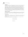


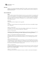

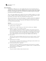


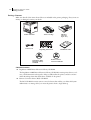


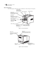
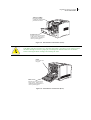
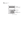

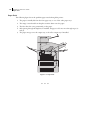


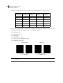
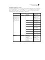
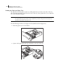
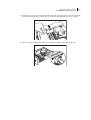
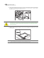
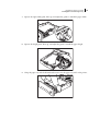

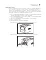


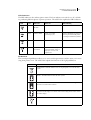
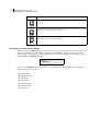
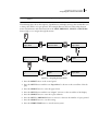
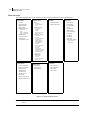

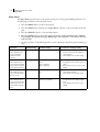
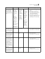
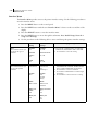

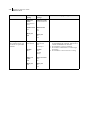
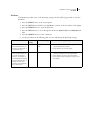
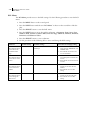
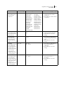
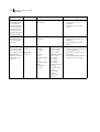
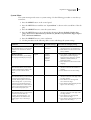
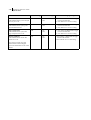
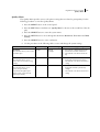
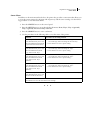

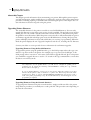

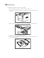
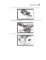
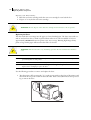

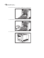


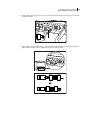

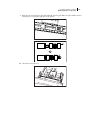
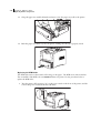
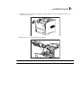
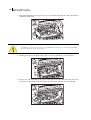
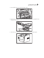

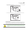

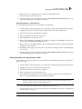


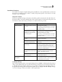

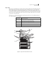

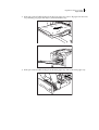

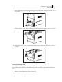
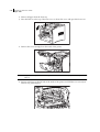
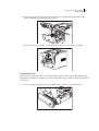
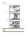
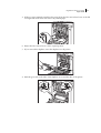
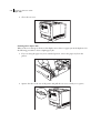

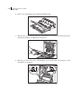
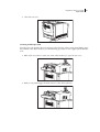
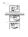


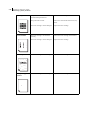

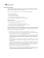
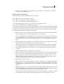
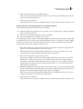
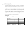
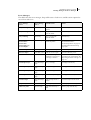

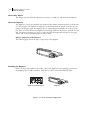

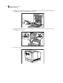
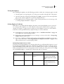

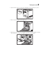


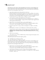
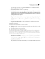
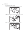


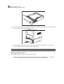

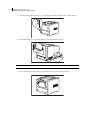


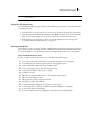
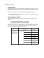
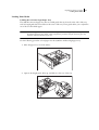

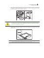
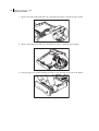
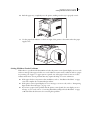


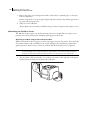


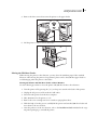


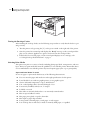
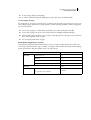
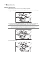
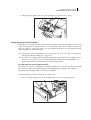
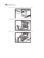
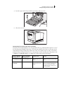

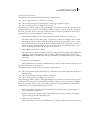
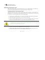


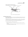


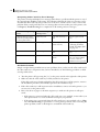
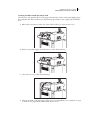
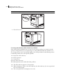
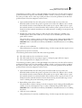


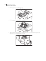

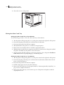


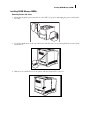
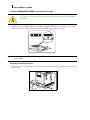
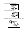
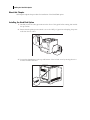
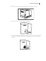
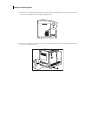

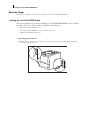


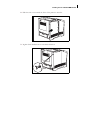
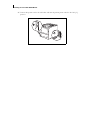


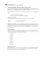

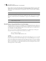
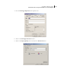


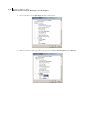


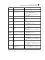


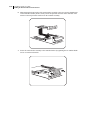
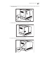
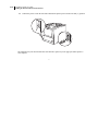
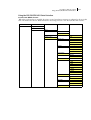

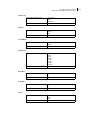
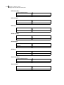
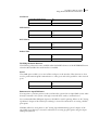
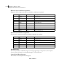


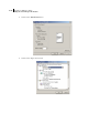
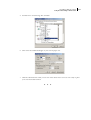


![téléchargez le dans son intégralité [ PDF - 28p - 3.62 Mo ] - Athis-Mons](http://vs1.manualzilla.com/store/data/006467605_1-ad483cc3c5528cc7d7f5459746157e0f-150x150.png)