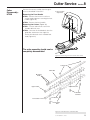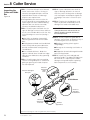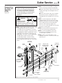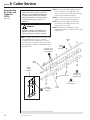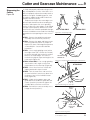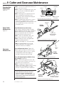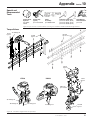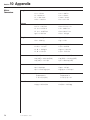
1
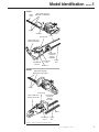
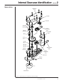
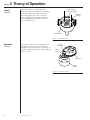
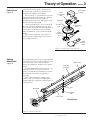
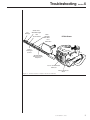
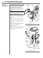
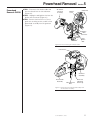
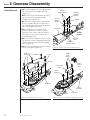
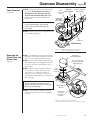
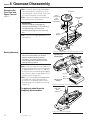
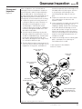
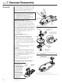
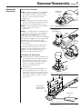
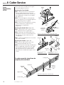
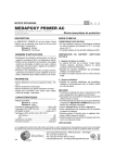
SHINDAIWA SERVICE MANUAL
SERVICE
MANUAL
GEARCASE AND CUTTERS
Shindaiwa HT230 and
DH230 Hedge Trimmers
HT230
DH230
DH2301
WARNING!
The engine exhaust from this product
contains chemicals known to the State of
California to cause cancer, birth defects
or other reproductive harm.
Service Manual
Shindaiwa HT230 and DH230
Hedge Trimmers
Gearcase and Cutters
Contents
Section
page
1 Model Identification/Specifications ....... 3
2 Internal Gearcase Identification ............. 5
3 Theory of Operation ................................ 6
4 Troubleshooting ...................................... 8
5 Powerhead and Cutter Removal .......... 10
6 Gearcase Disassembly/Inspection ...... 12
7 Gearcase Reassembly .......................... 16
8 Cutter Service ........................................ 18
9 Cutter and Gearcase Maintenance ...... 23
10 Appendix
Special and Recommended Tools .......... 25
Torque Specifications .............................. 25
Metric Conversions ................................. 26
Attention
Statements
WARNING!
A statement preceded by the triangle
Attention Symbol and the word
WARNING contains information that
should be acted upon to prevent serious
bodily injury.
CAUTION!
A statement preceded by the word
CAUTION contains information that
should be acted upon to avoid damaging
your machine.
IMPORTANT!
A statement preceded by the word
IMPORTANT is one that possesses
special significance.
2
䊚 Shindaiwa Inc. 1998
Model Identification
Section
1
HT230
Guide
Plate
Adjustable Shoulder
Bolts with Locking Nuts
HT2301
Cutters
Protector
Cover
Powerhead
Rear Handle and
Throttle Assembly
HT2302
Hand Guard
and Front
Handle
Assembly
Air Cleaner
Cover
Rear Handle
Bracket
Guide
Bar
Gearcase
DH230
Adjustable Shoulder
Bolts with Locking Nuts
DH2301
Cutters
Powerhead
Hand Guard
and Front
Handle
Assembly
Rear Handle and
Throttle Assembly
Cover
DH2302
Air Cleaner
Cover
Guide
Bar
Figure 1. Major Component Identification
䊚 Shindaiwa Inc. 1998
3
Section
1 Specifications
General Specifications HT230 & DH230
Drive and Cutters Specifications
Dimensions (L x W x H)
HT230-30 ..................... 990 x 210 x 210 mm
HT230-40 ................... 1330 x 210 x 210 mm
DH230-24 .................. 1080 x 250 x 210 mm
DH230-30 .................. 1220 x 250 x 210 mm
HT230 Blade ......... Double-action, single edge
Weight; engine and Cutter (less fuel)
HT230-30 .................... 5.5 kg (12.2 pounds)
HT230-40 .................... 6.0 kg (13.2 pounds)
DH230-24 .................. 5.7 kg (12.5 pounds)
DH230-30 ................... 5.9 kg (13.9 pounds)
DH230 Blade ....... Double-action, double edge
Blade Length
HT230-30 ......................................... 740 mm
HT230-40 ....................................... 1080 mm
DH230-24 ........................................ 605 mm
DH230-30 ........................................ 745 mm
Clutch Type ............. Fully automatic centrifugal
clutch, dry type
Engine Specifications
Gear Type ....................................... Spur gears
Engine Model ....................................... SHT230
Gear Reduction ...................................... 1:4.98
Type ..... 2-cycle, horizontal cylinder, air cooled
Gear Lubrication ............ Lithium-based grease
Bore x Stroke .......................... 32 mm x 28 mm
Standard Equipment
Displacement ........................................ 22.5 cc
Rear handle with integral controls, anti-vibe
mountings.
Dry Weight ...................... 2.6 kg (5.73 pounds)
Max. Output ....... 1.1 hp (0.81 kW) @ 8000 rpm
Fuel ................................. Gasoline-oil Mixture–
40:1 with Shindaiwa
Premium 2-cycle Engine Oil
Front handle with guard.
Tool set and blade cover (scabbard).
Options
Deflector shield (HT230 only)
Fuel Tank Cap., (HT230) ..... 0.7 liter/24 ounces
Fuel Tank Cap., (DH230) .... 0.6 liter/21 ounces
Carburetor ........ Walbro WYJ (diaphragm type)
Ignition .... Fully electronic, transistor controlled
Spark Plug ................................ Champion CJ8
Air Cleaner ................. Semi-wet type, silenced
Starting Method .............................. Recoil type
Specifications are subject to change without notice.
4
䊚 Shindaiwa Inc. 1998
Internal Gearcase Identification
Section
2
Nomenclature
Gearcase
Cover
Gasket
Felt Seal
Shielded
Bearings
Lower
Connecting
Rod
Thrust
Washer
Lower Guide
Plate
Pinion
Cam
Gear
Thrust
Washer
Shielded
Bearing
Upper Guide
Plate
Sealed
Bearing
Upper
Connecting
Rod
Gearcase
Grease
Fitting
HT2329
Clutch Drum
Figure 2. Internal Gearcase Components (shown inverted).
䊚 Shindaiwa Inc. 1998
5
Section
3 Theory of Operation
Clutch
Figure 3
Shoe (swings
outward to engage)
Crankshaft rotation is transferred to the
gearcase through a bonded-shoe centrifugal
clutch threaded to the engine crankshaft.
Increasing engine rpm causes the clutch
shoes to swing outward under centrifugal
force, engaging with and turning the clutch
drum on the gearcase.
Retraction
Spring
HT2337
Clutch Drum
Figure 3. Clutch Operation.
Gearcase
Figure 4
Clutch drum rotation is transferred directly to
the input pinion gear, which is in constant
engagement with the cam gear. The pinion-tocam gear combination reduces engine rpm by
a ratio of 1:4.98.
1:4.98
Reduction
Pinion
Gear
Cam Gear
HT2347
Figure 4. Reduction Gearing.
6
䊚 Shindaiwa Inc. 1998
Clutch
Drum
Theory of Operation
Cutter Drive
Figure 5
Each side of the cam gear is fitted with an
eccentric lobe, and the two eccentrics are
installed 180˚ opposite one another.
Each eccentric is also fitted with a connecting rod mounted on roller bearings, allowing
cam gear rotation to be converted to a
reciprocating action at the opposing or small
end of each connecting rod.
Connecting rod thrust is in turn controlled
by close-tolerances between the cam gear
faces and a set of hardened guide plates that
surround the small ends of the connecting
rods, held between a set of hardened guide
plates.
Via the connecting rods, cam rotation is
converted into reciprocating motion to drive
the cutting attachment.
Section
3
Lower Guide
Plate
Lower
Connecting
Rod
Cam Gear
Eccentric
Lobe
Reciprocating
Action
Upper
Connecting
Rod
HT2348
Upper
Guide
Plate
Figure 5. Cam Gear and Connecting Rods
Cutting
Attachment
Figure 6
The reciprocating end of each connecting rod
is bored to mate with a hardened drive stud at
the inner end of each of the two parallel
cutters, providing true “double action” performance.
To allow independent cutter movement, the
individual cutters are slot-mounted over
special shoulder bolts threaded into a stationary guide bar attached to the gearcase
assembly.
Cutters are identified as “upper” and
“lower”, and are available with appropriate
length guide bars to provide cutting swaths of
varying widths.
Upper Cutter
Guide Bar
(stationary)
Slot
Drive Stud
Shoulder
Bolt
Lower Cutter
HT230 Shown
HT2349
Figure 6. Cutter Drive Operation.
䊚 Shindaiwa Inc. 1998
7
Section
4 Troubleshooting
Performance and durability are highly dependent upon cutter condition, adjustment, and
lubrication.
For a truly “clean” cut, all cutters must be
sharp, undistorted, and in otherwise good
condition.
For consistent cutting action over the length
of the cutter, all shoulder bolts must be in
good condition and properly adjusted to
maintain cutter-to-cutter contact.
IMPORTANT!
Beyond outright abuse, gearcase life and
cutting performance are directly related
to both maintenance and adjustment.
Problem
Possible Cause
Remedy
Poor cutting performance
Shoulder bolts too loose
Adjust bolts per Section 8
Cutter teeth dull
Sharpen teeth per Section 8
Shoulder bolts loose
or worn
Adjust or replace per Section 8
Cutters not “tracking”
(non-parallel operation)
Worn shoulder bolt slots
Cutters not moving, or
move very slowly
(engine revs)
Clutch failure
Replace clutch shoe assembly
Internal gear failure
Overhaul gearcase
Cutters will not
disengage
Engine idle set too high.
Reset idle speed to 3000 ± 250 rpm
Clutch retraction spring is
broken
Replace clutch assembly
Drive stud is broken
Replace cutter per Section 8
Connecting rod failure
Replace connecting rod: inspect for
internal gearcase damage
Shoulder bolt(s) adjusted
too tight
Readjust per Section 8
Internal gearcase damage
Inspect/overhaul gearcase
Excessive noise from
gearcase
Gear or connecting rod
failure
Inspect/overhaul gearcase
Grease leaking from
gearcase at guide bar
Gearcase too full
Section 9
Felt seal damaged
Replace seal
Cover gasket damaged
Replace gasket
Water in gearcase (possible
outside storage)
Drain and refill per Section 9
One cutter not moving
Cutters/engine revs slow;
engine may overheat
Gearcase lube has white
“milky” appearance
8
䊚 Shindaiwa Inc. 1998
Troubleshooting
Tip
Damage
Section
4
Guide Plate
Worn/Damaged
Dirt
Accumulation
Worn
Shoulder
Bolt Slots
HT230 Shown
Poor
Lubrication
Dull or
Damaged
Cutters
HT2301
Shoulder Bolts
Worn/Incorrectly
Adjusted
Low or Contaminated
Lubricant
Internal Gearcase
Wear
Figure 7. Common Causes of Cutter or Gearcase Problems
䊚 Shindaiwa Inc. 1998
9
Section
5 Powerhead Removal
Powerhead
Removal–HT230
IMPORTANT!
Service procedures for the HT230 DH230
powerhead are similar to those for the
T230 trimmer and are described in
Shindaiwa Grass Trimmers, Brushcutters
and Lawn Edgers Service Manual, Form
60506.
Air Cleaner
(removed for
clarity)
Cable End
Throttle
Lever
CAUTION!
Impact-type power tools can damage the
hedge trimmer drive assembly.
Ignition
Wire
Connector
STEP 1. Disconnect the throttle cable end
from the throttle lever on the carburetor
(Figure 8).
HT2306A
STEP 2. Unplug the red ignition wire from the
ignition wire connector, and then temporarily remove the gearcase mounting bolt
to disconnect the black grounding wire
(Figure 8).
STEP 3. Remove the three 6 mm x 16 mm
gearcase mounting screws, and separate
the gearcase assembly from the
powerhead (Figure 9).
STEP 4. Remove the two 6mm x 35mm rear
handle bracket mounting screws, and lift
the rear handle assembly from the gearcase (Figure 9).
Black
Ground Wire
Red
Ignition
Wire
Gearcase
Mounting Bolt
Figure 8. Disconnecting the throttle cable
and ignition wiring
Powerhead
Gearcase
Assembly
HT2350
Rear
Handle
Handle
Bracket
Mounting
Screw
Gearcase
Mounting
Screw
Handle Bracket
Mounting Screw
Rear
Handle
Bracket
Gearcase
Mounting
Screw
Figure 9. Removing the Gearcase Assembly
and Rear Handle Bracket
10
䊚 Shindaiwa Inc. 1998
Mounting
Screw
Powerhead Removal
Powerhead
Removal–DH230
STEP 1. Disconnect the throttle cable end
from the throttle lever on the carburetor
(Figure 10).
Air Cleaner
(removed
for clarity)
Section
5
Cable End
Throttle
Lever
STEP 2. Unplug the red ignition wire from the
ignition wire connector (Figure 10).
STEP 3. Remove the three 6 mm x 16 mm
gearcase mounting screws, and lift off the
powerhead assembly from the gearcase
(Figure 11).
Ignition
Wire
Connector
DH2307A
Red
Ignition
Wire
Figure 10. Disconnecting the Throttle Cable.
Powerhead
DH2306A
Rear Handle
Assembly
Black Ground
Wire
Gearcase
Assembly
Gearcase
Mounting
Screws (3)
Figure 11. Removing the Powerhead Assembly from
the Gearcase Assembly
䊚 Shindaiwa Inc. 1998
11
Section
6 Gearcase Disassembly
Cutter Removal
STEP 1. With the gearcase oriented right-side
up, remove the cutter support bracket
(Figure 12):
■ Remove the two 6mm bracket retaining
nuts from where the guide bar studs
emerge from the gearcase.
■ Remove the single 6mm nut and washer
from the shoulder bolt at the outer end of
the holder bracket, and then lift the bracket
from over the guide bar studs.
STEP 2. Working from the bottom of the
gearcase, remove the six 4mm x 15mm
gearcase cover screws and then remove
the gearcase cover from the gearcase
assembly Figure 13).
Bracket
Retaining Nuts
Cutter
Support
Bracket
Cover
Screws
Washer
Gearcase
HT2332
HT230
Shown
Shoulder
Bolt
STEP 3. Lift out the felt grease seal. Unscrew
the two 6mm x 12mm guide plate retaining
screws, and then remove the lower guide
plate (Figure 14).
STEP 4. Remove and retain the thrust washer
from the cam gear (Figure 14).
Shoulder
Bolt Nut
(6mm)
Guide Bar
Mounting Studs
Figure 12. Removing the cutter support bracket.
Guide
Plate
Screws
Cover
Gasket
Felt
Grease
Seal
Lower Guide
Plate
Thrust
Washer
Gearcase
Cutter
Assembly
HT2333
Cam Gear
HT2351
Figure 13. Removing the gearcase cover.
12
䊚 Shindaiwa Inc. 1998
Figure 14. Grease seal and lower guide plate removal.
Gearcase Disassembly
Cutter Removal
continued
STEP 5. Gently lift the lower con-rod from the
cam gear. Be extremely careful not to
dislodge the roller bearings from the
large end of the connecting rod. All 52
bearing rollers must be accounted for!
(Figure 15)
Mark for
Lower
reinstallation!
Connecting
Rod
Section
6
Cutters and Guide
bar Assembly
BEARINGS
ARE NOT
CAPTIVATE!
IMPORTANT!
If the connecting rod is to be reused,
mark it now for correct orientation on
reassembly.
STEP 6. Remove the cutters and guide bar as
an assembly (Figure 15).
Gearcase
HT230 Shown
HT2330
Figure 15. Removing the upper con-rod and
cutters and guide bar assembly.
Removing the
Clutch Drum and
Pinion Shaft
Figure 16
STEP 1. Temporarily lock the pinion shaft by
placing a 10mm open-end wrench over the
two flats at the inboard end of the shaft.
Clutch Tool
P/N 99909-20230
A shaft or pin may
be used to provided
added leverage.
STEP 2. Insert tool p/n 99909-20230 into the
clutch drum bore, and engage the two pins
on the tool with the matching holes in the
clutch drum.
Turn
STEP 3. While using a firm grip to hold the
clockwise
10 mm wrench, loosen and remove the
to remove
clutch drum in a clockwise rotation. If
necessary, use a heat gun to soften the
ThreeBond™ thread adhesive on the clutch
drum threads.
CAUTION!
Do not overheat the clutch drum and
pinion shaft. Excessive heat can damage
the pinion shaft bearings.
STEP 4. Use a plastic or wooden mallet to
remove the pinion shaft from the gearcase
casting.
HT2331
10mm Open-end
Wrench
Pinion Gear
(note flats
provided for
wrench)
Figure 16. Removing the clutch drum.
䊚 Shindaiwa Inc. 1998
13
Section
6 Gearcase Disassembly
Removing the
Cam Gear and
Upper Con-rod
Figure 17
STEP 1. Gently lift the cam gear and upper
connecting rod from the gearcase. If the
connecting rod is to be reused, mark it now
for correct orientation on reassembly.
STEP 2. Remove the upper connecting rod
thrust washer from the gearcase.
Cam Gear
Upper
Connecting
Rod
(mark for
reinstallation)
Upper Guide
Plate
IMPORTANT!
Careless handling will dislodge the
connecting rod bearings. The connecting
rod roller bearings are loose in the
connecting rod large end, and are easily
lost.
STEP 3. Remove the upper guide plate from
the gearcase.
Thrust
Washer
HT2352
Bearing Removal
Figure 17. Removing the cam gear and upper con-rod
IMPORTANT!
Gearcase bearing bores can be damaged by improper bearing removal
techniques. If a bearing puller must be
used, be extremely careful not to “cock”
bearings during removal.
STEP 1. Use a heat gun or similar appliance
to warm the gearcase cover bearing bores
to approximately 212˚F (100˚C ), and then
remove the two cover bearings by tapping
the cover face down sharply against a flat
wooden surface (Figure 18).
STEP 2. Use a bearing puller equipped with
reversible jaws and a slide-hammer to
remove the cam bearing and the clutch
drum bearing from the gearcase housing
(Figure 19).
The gearcase should now be
completely disassembled
Expanding the
Bearing Bore
Heat
Gun
HT2335
Cover
Tap the cover
sharply
Wood
Block
HT2343
Figure 18. Removing gearcase-cover bearings.
Puller with
Slide
Hammer
HT2345
Figure 19. Using a bearing puller.
14
䊚 Shindaiwa Inc. 1998
Gearcase Inspection
Cleanup and
Inspection
Figure 20
Prior to inspection, use a solvent bath to
thoroughly clean all components except the
connecting rods, and then wipe or blow dry
with compressed air. Connecting rods can
also be cleaned with solvent, provided that all
big-end bearing rollers (52 rollers per connecting rod) are accounted for after cleaning.
1. Inspect the gearcase housing and cover
castings for obvious cracks, distortion, or
damage to the bearing bores or cover
sealing flanges, and discard if noted.
Check the gearcase casting for stripped or
otherwise damaged threaded areas, and
discard if unrepairable.
Section
6
found. Be especially alert for damage to the
threaded end on the pinion gear, and also
to any pitting or other damage to the
connecting rod drive lobes on the cam
gear.
4. Inspect the clutch drum for cracks, distortion, or damage to the hub area, and
replace if noted.
5. Use a strong lens to inspect the connecting
rod roller bearings for damage such as
chipping or pitting. Inspect the connecting
rod small-end bore for damage or out-ofround; and the sides for signs of excessive
friction. Any damage or excessive wear to
either the connecting rod or roller bearings
requires connecting rod replacement as a
complete assembly.
2. Visually inspect all bearings for physical
damage, especially to protective covers on
sealed or shielded bearings, and discard if
found. Spin all bearings by hand, and
discard any bearing that feels rough, loose,
or is otherwise difficult to spin.
6. Inspect the working surfaces of both guide
plates, and replace if any damage or
measurable wear is noted.
3. Examine both the pinion and cam gears for
excessive wear or obvious damage such as
chipped or missing teeth, and replace if
Cutter inspection is described in
Section 8, Cutters.
Cover or housing
damaged
1
Guide plate
scoring
6
Worn or damaged
bearings
2
Connecting
rod wear
5
Clutch drum
threads damaged
4
HT2329B
3
Gear teeth damaged
or missing/wear or
pitting to the cam lobe
Figure 20. Inspecting gearcase components.
䊚 Shindaiwa Inc. 1998
15
Section
7 Gearcase Reassembly
Reassembly
Reassembly is basically the reverse of assembly, with the additions or exceptions as noted
below. Note also that torque specifications
have been listed for several key areas.
CAUTION!
The hedge trimmer can be damaged by
overtightening of fasteners. For a
complete listing of recommended torque
specifications, see the Appendix.
Bearing
Bearing Installations (Figure 21)
Shindaiwa recommends expanding each
bearing bore with a heat gun or other appliance set to preheat the bore to approx. 100˚C
(212˚F). Individual bearings can then be easily
positioned by hand without the risk of damage
to the bearing bore. Note that hammering or
pounding bearings in place can damage both
bearings and bearing bores, and is not
recommended.
Heat
Gun
HT2335A
Figure 21. Bearing Installation.
Lower Thrust
Washer
Lower Connecting
Rod
All rollers aligned.
Bearing count: 52
Connecting Rods (Figure 22)
■ During connecting rod installation, be
extremely careful not to dislodge the
individual rollers from their bearing races.
Cam
Gear
■ If the original connecting rods are being
reused, be sure to reinstall each connecting
rod in the same location and orientation as
removed.
■ Install the upper and lower thrust washers
in the reverse order of removal.
HT2336
Upper
Connecting
Rod
HT2348A
Guide Bar
Install the guide bar assembly in the reverse
order of removal, and firmly tighten all fasteners. If a torque wrench is available, torque
both of the guide bar mounting stud nuts and
also the two guide plate screws to
50-70kgf-cm.
■ Install a new felt seal p/n 20870-61630
during assembly (Figure 23).
Upper Thrust
Washer
Figure 22. Reinstall connecting rods in original location
and orientation.
Install new seal
p/n 20870-61630
■ Lubricate and adjust all shoulder bolts as
described in Section 9 of this manual.
IMPORTANT!
The gearcase
assembly contains
both shielded and
sealed bearings!
The clutch-side
bearing on the
pinion shaft must
be a sealed-type
bearing, or grease
may enter the
clutch area.
16
䊚 Shindaiwa Inc. 1998
Sealed
Bearing
Shielded
Bearing
HT2342
Figure 23. Install a new felt grease seal.
Gearcase Reassembly
Reassembly
Procedures
Clutch Drum Installation
STEP 2. Temporarily lock the pinion shaft by
placing a 10mm open-end wrench over the
two flats at the inboard end of the shaft.
STEP 4. If a torque wrench is available, finaltighten the clutch drum to 170-190kgf-cm.
HT2346
Figure 24. Applying thread adhesive to the
pinion gear threads.
Torque Drum to
170-190kgf-cm
Clutch
Tool
Lubrication and Inspection (Figure 26)
Prior to gearcase cover installation, hand-pack
the gearcase to approx. 50-70% capacity with
Shindaiwa p/n 37-57 Gearcase Lube or
equivalent high quality lithium-based grease
(see Section 9).
Install the gearcase cover, and rotate the
clutch drum by hand to check for internal
binding. If noted, any binding or other such
problems must be corrected before the
gearcase can be returned to service.
7
ThreeBond™
p/n 13-60
STEP 1. Apply several drops of ThreeBond™
p/n 13-60 thread adhesive to the pinion
gear threads, and then install the clutch
drum in a counter-clockwise rotation
(Figure 24).
STEP 3. Use tool p/n 99909-20230 to tighten
the drum firmly on the shaft
(Figure 25).
Section
10mm
Open End
Wrench
HT2341
Installation and Adjustments
■ Install the gearcase and rear handle on the
powerhead in the reverse order of removal,
and firmly tighten the three gearcase-topowerhead mounting screws. If a torque
wrench is available, final-tighten the
gearcase mounting screws to
70-100 kgf-cm.
■ Confirm correct throttle cable adjustment
by measuring throttle lever “free-play” of
0.010-0.020”. If necessary, turn the cable
adjustment fitting on the carburetor in or out
until throttle free-play is within the above
specifications.
HT2331
Figure 25. Tightening the clutch drum.
Approximate
Capacity: 40-50
grams (1.6 oz.)
HT230 Shown
Grease Gun
HT2333A
Figure 26. Lubricating the gearcase.
䊚 Shindaiwa Inc. 1998
17
Section
8 Cutter Service
Cutter
Disassembly–
HT230
Remove the cutter assembly from the gearcase as described in Section 5.
Flange
Nut
Removing the Front Handle
STEP 1. Remove the 6mm nut and washer
from the hand guard stud, remove the
shoulder-bolt nut and washer, and then lift
the hand guard assembly from the guide
bar (Figure 27).
STEP 2. If the hand grip is to be replaced,
use a sharp knife to cut the grip lengthwise
before peeling it from the guard.
5 mm
Stud
STEP 3. Remove the two protector mounting
screws and washers, and then lift the
protector from the guide bar
(Figure 28).
HT2344
Shoulder
Bolt
Removing the Guide Plate (Figure 29)
Cut off the
hand grip to
remove.
STEP 1. Remove the 5 mm x 8 mm screw at
the outboard end of the guide plate.
HT2344A
STEP 2. Working at the inboard end of the
guide plate, remove the shoulder bolt lock
nut and then unscrew and remove the
shoulder bolt.
STEP 3. Slide the guide plate from the end of
the cutter assembly.
Figure 27. Removing the Front Handle and Shield.
Guide
Plate
Protector
Screw
Removing the Cutters (Figure 30)
STEP 1. Loosen and remove each of the
remaining shoulder bolt lock nuts.
STEP 2. Unscrew all remaining shoulder bolts
from the guide bar, and remove the single
flat washer from beneath each shoulder
bolt head. Note the use and location of
three different shoulder bolt lengths on the
HT230.
The cutter assembly should now be
completely disassembled.
HT2353
Guide
Plate
Shoulder
Bolt
Figure 28. Removing
the Protector.
HT2354
Figure 29. Removing the
Guide Plate.
Locking Nut
HT2355
Guide Bar
Washer
Mounting
Studs
Shoulder
Bolt
Shoulder
Bolt Slot
Upper Cutter
Figure 30. HT230 Cutters and Guide Bar
Lower Cutter
18
䊚 Shindaiwa Inc. 1998
Cutter Service
Cutter
Disassembly–
HT230
Remove the cutter assembly from the gearcase as described in Section 5.
Section
8
6 mm x 35 mm
Capscrews
Removing the Front Handle
STEP 1. Remove the two 6 mm x 35 mm
socket head capscrews securing the front
handle (Figure 31).
STEP 2. Remove the front handle.
Removing the Cutters (Figure 32)
STEP 1. Loosen and remove each of the
shoulder bolt lock nuts.
STEP 2. Unscrew all shoulder bolts from the
guide bar, and remove the single flat
washer from beneath each shoulder bolt
head (Figure 32).
The cutter assembly should now be
completely disassembled.
DH2306B
Figure 31. Removing the Front Handle and Shield.
Locking Nut
Guide Bar
Mounting
Studs
Washer
Upper Cutter
Shoulder
Bolt Slot
Washer
Lower Cutter
Shoulder
Bolt
Figure 32. DH230 Cutters and Guide Bar
䊚 Shindaiwa Inc. 1998
19
Section
8 Cutter Service
Inspecting the
Cutter and Guide
Bar
Figure 33
STEP 1. Check the drive pin at the inboard
end of each cutter. A loose, missing, or
otherwise damaged drive pin cannot be
repaired. Where noted, such damage
requires cutter replacement.
■ Damaged drive pins are most often the
result of allowing the moving blade tips to
impact against a wall or sidewalk during
operation, but can also be caused by
incorrect shoulder bolt adjustment.
STEP 2. Visually inspect the blade slots for
signs of damage or unusual wear, and then
test-fit a new shoulder bolt in each slot. Any
of the following are cause for rejecting a
cutter:
■ Slot sides are irregular (nonparallel),
indicating operation with worn shoulder
bolts.
STEP 4. Inspect individual cutter teeth for
signs of damage, distortion, or unusual
wear. Any cutter showing wear or damage
such that repairs would require significant
reshaping of the cutter is cause for rejection.
STEP 5. Examine the shoulder bolts, and
reject any bolt with visible body wear or
damage to its head or threaded areas.
IMPORTANT!
Cutter performance and service life are
directly related to shoulder bolt lubrication and adjustment.
STEP 6. Visually inspect the guide bar for
damage, unusual wear, or distortion. Any of
the following are cause for rejection:
■ Galling between blade and shoulder bolt
head. Usually indicates poor lubrication,
possibly combined with overtightening
shoulder bolts.
■ Bending or twisting (check against
straightedge).
■ Loss of blade thickness; blade slot
appears "dished" when viewed from edge.
Indicates poor lubrication, dirty operating
conditions.
■ Stripped or otherwise damaged shoulder
bolt mounting threads.
STEP 3. Visually inspect the inner working
surfaces of the guide plate. If evidence of
galling or grooving are noted, the plate
must be replaced.
Check for damaged
drive pins
■ Damage to the mounting stud shanks or
threads.
STEP 7. Inspect the front hand grip and
guard assembly. The rubber hand grip can
be serviced as a separate part number;
damage to the guard requires replacing
both components as an assembly.
Check for
damaged
cutter
teeth
HT2340
HT230 Shown
Check for
damaged
shoulder bolts
Check for
damaged or
worn slots
Figure 33. Inspecting the cutter and guide bar (shown inverted).
20
䊚 Shindaiwa Inc. 1998
"Dished"
appearance
Cutter Service
Reassembling
the Cutter and
Guide Bar–
HT230
Figure 34
Section
8
STEP 2. Install the front handle assembly
over its mounting stud and shoulder bolt.
IMPORTANT!
Unless the cutters are being replaced
with new or reconditioned components,
all cutting teeth should be sharpened
before reassembly. For recommended
sharpening procedures, please see
Section 9.
■ Install a flat washer and nut over the front
handle mounting stud, and tighten the nut
securely.
■ Install a flat washer and a new shoulder
bolt locknut over the shoulder bolt at the
hand grip, but do not tighten the nut at this
time.
WARNING!
STEP 3. Install the protector and holder
support bracket over the innermost shoulder bolt, and loosely secure the assembly
with a spring washer and shoulder bolt
locknut. Install and firmly tighten the
5 mm x 8 mm screw through the remaining
protector mounting hole.
Incorrect assembly
could expose the
operator to serious injury! Read and
follow assembly instructions carefully!
STEP 1. Lightly lubricate both the cutters and
the guide bar with clean oil, and then
assemble all three components as shown.
Install–but do not tighten–a flat washer and
the appropriate length shoulder bolt in each
guide bar slot except the slot beneath the
guide plate. The 6 mm x 20 mm guide plate
shoulder bolt should now be loosely
installed, but without a washer. Finally,
install and firmly tighten the 5 x 8mm hex
bolt through the remaining hole in the guide
plate.
STEP 4. Loosely install a new locknut over
each of the remaining shoulder bolts.
STEP 5. Install the guide bar and cutter
assembly on the hedge trimmer in the
reverse order of removal.
STEP 6. Adjust all shoulder bolts as described in Section 9, “Gearcase and Cutter
Maintenance”.
Install the
front handle
Hand
Guard
2
Hand
Grip
Cutter
Support
Bracket
Lubricate and
assemble cutters
and guide bar
Guide
Bar
6 x 8mm
Install the
guide plate
5
1
Install
new 4
locknuts
Install the 3
protector and
cutter support
bracket
Protector
6 x 20mm
6
Washer
HT2328
Shoulder
Bolt
6 x 32mm
Lower
Cutter
Upper
Cutter
6 x 20mm
Adjust all
shoulder bolts
6 x 25mm
Figure 34. Reassembling the HT230 Cutter and Guide Bar.
䊚 Shindaiwa Inc. 1998
21
Section
8 Cutter Service
Reassembling
the Cutter and
Guide Bar–
HT230
Figure 34
STEP 2. Install the holder support bracket
over the innermost shoulder bolt, and
loosely secure the assembly with a spring
washer and shoulder bolt locknut.
IMPORTANT!
Unless the cutters are being replaced
with new or reconditioned components,
all cutting teeth should be sharpened
before reassembly. For recommended
sharpening procedures, please see
Section 9.
STEP 3. Loosely install a new locknut over
each of the remaining shoulder bolts.
STEP 4. Install the guide bar and cutter
assembly on the hedge trimmer in the
reverse order of removal.
WARNING!
STEP 5. Adjust all shoulder bolts as described in Section 9, “Gearcase and Cutter
Maintenance”.
Incorrect assembly could expose the
operator to serious injury! Read and
follow assembly instructions carefully!
STEP 1. Lightly lubricate both the cutters and
the guide bar with clean oil, and then
assemble all three components as shown.
Install–but do not tighten–a flat washer and
the appropriate length shoulder bolt in each
guide bar slots.
Lubricate and
assemble cutters
and guide bar
Guide
Bar
Install
new 3
locknuts
1
Upper
Cutter
Cutter
Support
Bracket
4
Install cutter
assembly onto
hedge trimmer
6 mm x 20 mm
5
Adjust all
shoulder bolts
2
Install the
cutter support
bracket
HT2361
Figure 35. Reassembling the DH230 Cutter and Guide Bar.
22
䊚 Shindaiwa Inc. 1998
Lower
Cutter
Cutter and Gearcase Maintenance
Sharpening the
Cutters
Figure 36
A sharp and properly adjusted cutting assembly should produce a clean, chisel-like cut. A
dull or improperly adjusted assembly tends to
produce a rougher, shredding-type cut, and
also places additional demands on both the
operator and the machine.
Frequent touch-up of the cutter edges can
be accomplished without disassembling the
machine, and requires the use of grinding
stones to dress the cutter edges as described
in Steps 3 and 4 (below). Where one or more
cutter teeth have suffered repairable damage,
however, Shindaiwa recommends the following
procedure for resharpening the cutter assembly:
35°
Section
9
20°
90°
45°
43°
HT2358
HT230 ONLY
DH230 ONLY
Figure 36. Sharpening angles.
STEP 1. Remove the guide bar and cutter
assembly from the trimmer (Section 5).
STEP 2. Remove the upper and lower cutters
from the guide bar (Section 8). Repair or
replace any worn or damaged components
as described in “Cutter and Guide Bar
Inspection.”
STEP 3. Use a rough grinding stone held at
the angle shown (45°, HT230; 43°, DH230)
to remove damage and restore the original
bevel to the cutter edges. Use care to
maintain the original shape and angle of the
cutter teeth (Figure 37).
HT230: 45°
DH230: 43°
HT2356
Figure 37. Grinding and sharpening the cutter bevels.
STEP 4. HT230 ONLY. Use a rough grinding
stone held at a 35° angle to restore the
original bevel to the cutter tips (Figure 38).
HT230 ONLY
STEP 5. Use a fine oil stone to smooth the
edges produced in Steps 3 and 4.
STEP 6. Turn the cutter over, and use a fine
oil stone held flat to remove any burrs from
the bottom faces of the individual cutter
teeth (Figure 39).
STEP 7. Lightly oil the upper cutters and
guide bar. Reassemble the guide bar and
cutters (Section 8), but do not tighten the
shoulder bolts or locknuts at this time.
35°
HT2357
Figure 38. Beveling the cutter tips.
STEP 8. Reinstall the cutter assembly on the
hedge trimmer (Section 5).
Back of
blade
HT2359
Stone flat
against the
blade
Figure 39. Removing burrs.
䊚 Shindaiwa Inc. 1998
23
Section
9 Cutter and Gearcase Maintenance
Shoulder Bolt
Adjustment
STEP 1. Loosen all shoulder bolt locknuts (at
least one full turn each).
Figure 40
STEP 2. Tighten all shoulder bolts firmly, and
then loosen each shoulder bolt approximately 1/4-1/2 turn.
Locknut
STEP 3. Working from the powerhead, lock
each shoulder bolt in place by firmly
tightening its locknut while preventing the
shoulder bolt from turning.
STEP 4. Shoulder bolt adjustment is correct
when there is (approximately) a 0.025–
0.050mm gap between the cutter faces and
the shoulder bolt washer can be freely
rotated by hand.
Daily Cutter
Maintenance
Figure 41
Guide Bar
Cutters
HT2321
Shoulder
Bolt
Washer should
turn freely
Figure 40. Adjusting Shoulder Bolts.
Lubricate
Cutters
HT230
SHOWN
Daily Maintenance (cutters only)
A dull or poorly adjusted cutting assembly
requires additional operator effort, and places
additional demands on the hedge trimmer
gearcase and powerhead. For maximum
cutter performance and service life:
Check and
Adjust Shoulder
Bolts Daily
STEP 1. Adjust shoulder bolts daily, and
replace when visible wear is detected.
HT2317
STEP 2. Lubricate cutters and guide bar
frequently during operation.
Figure 41. Lubricating the Cutters and Guide Bar.
■ Clean 30-weight oil is recommended
■ Some biodegradable oils can help
reduce “brownout” caused by excess
lubricant on delicate shrubbery.
Gearcase
Maintenance
Grease
Gun
Every 20 Operating Hours (Figure 42)
■ Top off gearcase grease level by using a
lever-type grease gun to force 1-2 strokes
of high quality lithium-based grease
through the gearcase grease fitting.
Every 100 operating hours/before longterm storage (Figure 43)
HT230
SHOWN
HT2322A
Figure 42. Adding Grease with a Grease Gun.
STEP 1. Remove the gearcase cover, and
use solvent and a soft brush to remove all
old grease from the gearcase.
STEP 2. Hand-pack the gearcase with
approx. 40-50 grams (about 1.6 oz.) of high
quality lithium-based grease to about
50-70% of capacity. DO NOT OVERFILL!
IMPORTANT!
Over-lubrication could cause the gearcase to run slower (and hotter) than
normal. In addition, over-lubrication could
cause excess grease to leak past the felt
seal in the gearcase.
HT2323
HT230
SHOWN
Hand-pack gearcase
to 50-70% capacity
Figure 43. Hand-packing the gearcase.
24
䊚 Shindaiwa Inc. 1998
Appendix
Section
10
Special and
Recommended
Tools
CYL-56
HT2346A
Clutch Drum
Spanner
p/n 9990920230
Piston Stop
(nylon)
p/n 22155-96240
Puller
Assembly
p/n 20000-96104
T-Wrench (allen type)
p/n 22155-96521 (3mm)
p/n 22155-96531 (4mm)
p/n 22155-96540 (5mm)
ThreeBond™
Thread Sealant
p/n 13-60
Figure 44. Special tools recommended for servicing the Shindaiwa HT230 and DH230 Hedge Trimmer.
Torque Values
50-70 70-100 kgf-cm
kgf-cm
70-100
kgf-cm
70-100
kgf-cm
40-50
kgf-cm
HT2328
HT230
DH230
50-70
kgf-cm
Adhesive
p/n 13-60
HT2350
DH2306A
90-120 kgf-cm
70-100 kgf-cm
90-120 kgf-cm
170-190
kgf-cm
70-100 kgf-cm
HT2329C
Figure 45. Shindaiwa Hedge Trimmer Torque Values.
䊚 Shindaiwa Inc. 1998
25
Section
10 Appendix
Metric
Conversions
Length
1 in. = 25.4 mm
1 mm = .03937 in.
1 in. = 2.54 cm
1 cm = .3937 in.
1 ft. = 30.48 cm
1 cm = .0328 ft.
1 ft. = .304 meter
1 meter = 3.28 ft.
1 mile = 1.609 km
1 km = .621 mile
1 cu. in. = 16.39 cc
1 cc = .061 cu. in.
1 cu. in. = .061 liter
1 liter = 61.02 cu. in.
1 fl. oz. = 29.574 ml
1 ml = .0338 fl. oz.
1 fl. oz. = .02957 liter
1 liter = 33.81 fl. oz.
1 gal. = 3.785 liter
1 liter = .264 gal.
1 oz. = 28.35 gm
1 gm = .0353 oz.
1 lb. = .4536 kg
1 kg = 2.2 lb.
1 in. lb. = 1.152 kg/cm
1 kg/cm = .868 in. lb.
1 in. lb. = .112 n/m
1 n/m = 8.844 lb.
1 ft. lb. = .138 kg/m
1 kg/m = 7.23 ft. lb.
1 ft. lb. = 1.36 n/m
1 n/m = .737 ft. lb.
1 hp (SAE) = .746 kw
1 kw = 1.34 hp (SAE)
1 hp (SAE) = .9861 hp (DIN)
1 hp (DIN) = 1.104 hp (SAE)
1 hp (SAE) = 1.017 psi
1 psi = .9836 hp (SAE)
1 psi = .0689 bar
1 bar = 14.5 psi
1 psi = 6.89 kpa
1 kpa = .145 psi
1 psi = .07031 kg/sq cm
1 kg/sq cm = 14.22 psi
Temperature
°F to °C =
Temperature in
F - 32 x 5/9 (.555)
°C to °F =
Temperature in
C x 9/5 (1.8) + 32
Miscellaneous
1 mph = 1.6 km/hr
1 km/hr = .625 mph
1 mpg = .425 km/liter
1 km/liter = 2.35 mpg
Volume
Weight
Force
Power
Pressure
26
䊚 Shindaiwa Inc. 1998
Notes
䊚 Shindaiwa Inc. 1998
27
1998 Shindaiwa Inc. Form No. 61305-1 Printed in U.S.A.
Shindaiwa is a registered trademark of Shindaiwa Inc.
SHINDAIWA SERVICE MANUAL
Shindaiwa Inc.
11975 SW Herman Road
P.O. Box 1090
Tualatin, OR 97062
Phone 503 692-3070
FAX 503 692-6696
www.shindaiwa.com