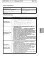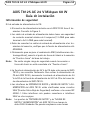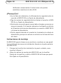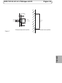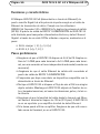
1
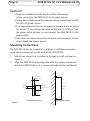
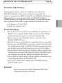
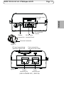
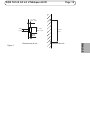
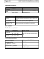
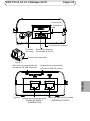
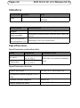
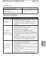
INSTALLATION GUIDE AXIS T8125 AC 24 V Midspan 60 W ENGLISH FRANÇAIS DEUTSCH ITALIANO ESPAÑOL Legal Considerations Australia - This digital equipment fulfills the Electromagnetic Compatibility (EMC) Korea - ࢇ̛̛Еɼࢽࡈ%̗ࢷળࢶଢ̛̛Ի۰ ࣯Իɼࢽ߾۰ࡈیଜЕʨࡶּࢶࡳԻଜֲֻҘ एࠇ߾۰ࡈیଟܹݡТЬ Video and audio surveillance can be prohibited by laws that vary from country to country. Check the laws in your local region before using this product for surveillance purposes. This equipment has been designed and tested to fulfill applicable standards for: • Radio frequency emission when installed according to the instructions and used in its intended environment. • Immunity to electrical and electromagnetic phenomena when installed according to the instructions and used in its intended environment. USA - This equipment has been tested using a shielded network cable (STP) and found to comply with the limits for a Class B digital device, pursuant to part 15 of the FCC Rules. These limits are designed to provide reasonable protection against harmful interference in a residential installation. This equipment generates, uses and can radiate radio frequency energy and, if not installed and used in accordance with the instructions, may cause harmful interference to radio communications. However, there is no guarantee that interference will not occur in a particular installation. If this equipment does cause harmful interference to radio or television reception, which can be determined by turning the equipment off and on, the user is encouraged to try to correct the interference by one or more of the following measures: • Reorient or relocate the receiving antenna. • Increase the separation between the equipment and receiver. • Connect the equipment into an outlet on a circuit different from that to which the receiver is connected. • Consult the dealer or an experienced radio/TV technician for help. Europe - This digital equipment fulfills the requirements for RF emission according to the Class B limit of EN 55022. This product fulfills the requirements for immunity according to EN 55024 residential and commercial environments. Canada - This Class B digital apparatus complies with Canadian ICES-003. requirements for RF emission according to the Class B limit of AS/NZS CISPR 22. Japan - この装置は、クラスB 情報技術装置です。 この装置は、家庭環境で使用することを目 的として いますが、この装置がラジオやテレビジョン受信機 に近接して使用されると、 受信障害を引き起こすこ とがあります。 取扱説明書に従って正しい取り扱い をして下さい。 Safety This product complies with IEC/EN/UL 60950-1, Safety of Information Technology Equipment. Trademark The product described in this Installation Guide is a licensed product of PowerDsine. RoHS This product complies with both the European RoHS directive, 2002/95/EC, and the Chinese RoHS regulations, ACPEIP. WEEE Directive The European Union has enacted a Directive 2002/96/EC on Waste Electrical and Electronic Equipment (WEEE Directive). This directive is applicable in the European Union member states. The WEEE marking on this product (see right) or its documentation indicates that the product must not be disposed of together with household waste. To prevent possible harm to human health and/or the environment, the product must be disposed of in an approved and environmentally safe recycling process. For further information on how to dispose of this product correctly, contact the product supplier, or the local authority responsible for waste disposal in your area. Business users should contact the product supplier for information on how to dispose of this product correctly. This product should not be mixed with other commercial waste. Support Should you require any technical assistance, please contact your Axis reseller. If your questions cannot be answered immediately, your reseller will forward your queries through the appropriate channels to ensure a rapid response. If you are connected to the Internet, you can: • download user documentation and software updates • find answers to resolved problems in the FAQ database. Search by product, category, or phrase • report problems to Axis support staff by logging in to your private support area • chat with Axis support staff (selected countries only) • visit Axis Support at www.axis.com/techsup/ Liability Every care has been taken in the preparation of this document. Please inform your local Axis office of any inaccuracies or omissions. Axis Communications AB cannot be held responsible for any technical or typographical errors and reserves the right to make changes to the product and documentation without prior notice. Axis Communications AB makes no warranty of any kind with regard to the material contained within this document, including, but not limited to, the implied warranties of merchantability and fitness for a particular purpose. Axis Communications AB shall not be liable nor responsible for incidental or consequential damages in connection with the furnishing, performance or use of this material. This product is only to be used for its intended purpose. Contact Information Axis Communications AB Emdalavägen 14 223 69 Lund Sweden Tel: +46 46 272 18 00 Fax: +46 46 13 61 30 www.axis.com Safeguards Please read through this Installation Guide carefully before installing the product. Keep the Installation Guide for further reference. • • • • • • • • Store the Axis product in a dry and ventilated environment. Avoid exposing the Axis product to vibration, shocks or heavy pressure and do not install the camera on unstable brackets, unstable or vibrating surfaces or walls, since this could cause damage to the product. Only use applicable tools when installing the Axis product; excessive force could cause damage to the product. Do not use chemicals, caustic agents, or aerosol cleaners. Use a damp cloth for cleaning. Use only accessories that comply with technical specification of the product. These can be provided by Axis or a third party. Use only spare parts provided by or recommended by Axis. Do not attempt to repair the product by yourself, contact Axis or your Axis reseller for service matters. This Axis product must be used in compliance with local laws and regulations. To use this Axis product outdoors, it shall be installed in an approved outdoor housing. The Axis product should be installed by a trained professional. Observe relevant national and local regulations for the installation. Transportation • When transporting the Axis product, use the original packaging or equivalent to prevent damage to the product. ENGLISH • • AXIS T8125 AC 24 V Midspan 60 W Page 7 AXIS T8125 AC 24 V Midspan 60 W Installation Guide Safety Information AC Power inlet set: • The 24 V AC power source must be near the AXIS T8125 and easily accessible. To remove AC power from the AXIS T8125, disconnect the 24 V AC power inlet from either the 24 V AC power source or the AXIS T8125 power connector. • The AXIS T8125 DATA IN and DATA & POWER OUT interfaces are qualified as SELV (Safety Extra-Low Voltage) circuits according to IEC 60950-1. These interfaces can only be connected to SELV interfaces on other equipment. Note: The AXIS T8125 "DATA IN" and "DATA & POWER OUT" ports are shielded RJ45 data sockets. They cannot be used as Plain Old Telephone Service (POTS) sockets. Only RJ45 data connectors may be connected to these sockets. ENGLISH • The power connector supplied with the AXIS T8125 has 2 terminals. See Figure 2. • The power inlet cables must be rated for a minimum current capacity of 6 amps (12 AWG for each terminal or 2X16 AWG for each terminal). • Before connecting power inlet cables to the connector terminals, verify that the power source is turned OFF. • Only for improved EMI performance, connect chassis ground connection to "Earth Ground" connection at the working area. Note: There is no safety hazard when the chassis ground connection is not connected to the “Earth Ground”. Page 8 AXIS T8125 AC 24 V Midspan 60 W Caution! • Read the Installation Guide and the Safety Information before connecting the AXIS T8125 to its power source. • Follow basic electricity safety measures when connecting the AXIS T8125 to its power source. • A voltage mismatch can cause equipment damage and may pose a fire hazard. If the voltage indicated on the label is different from the power outlet voltage, do not connect the AXIS T8125 to this power outlet. • Take extra care when connecting the power inlet terminals, so they do not touch the chassis ground. Mounting Instructions The AXIS T8125 may be located on a desktop, or wall/bench mounted using the mounting slots on the back of the AXIS T8125. 1. 2. Mount two screws (not included) in the wall or shelf as shown in Figure 1. Align the AXIS T8125 mounting slots with the surface screws and adjust the AXIS T8125 so it is securely attached to the wall/bench. 1.5 - 2 mm (0.06” - 0.08”) 3 mm (0.12”) 5.8 - 7 mm (0.23” - 0.27”) 91.7 mm (3.61”) 2 mm (0.08”) Screw dimensions Figure 1 Screw placement AXIS T8125 AC 24 V Midspan 60 W Page 9 Functions and Features • Alt A: pins 1, 2 (-) & 3, 6 (+) • Alt B: 4, 5 (+) and 7, 8 (-) Preliminary Steps • Ensure that 24 V AC is applied to the AXIS T8125. Use cables of 12 AWG for each terminal or 2X16 AWG for each terminal, with an appropriate separate ground connection (when needed). • Ensure that the output Ethernet cable is connected to the DATA & POWER OUT port. • Verify that a power-ready Ethernet compatible device is connected. • Do not cover the AXIS T8125 or block the airflow to the PoE with any foreign objects. Keep the AXIS T8125 away from excessive heat and humidity, and free from vibration, dust and direct sunlight. • Ensure that the cable length from Ethernet network source to the terminal does not exceed 100 meters (333 feet). The AXIS T8125 is not a repeater and does not amplify the Ethernet data signal. • Use a splitter if desired. Ensure that the splitter is connected close to the terminal and not on the AXIS T8125. • No “on-off” switch exists; simply plug the AXIS T8125 into a 24 V AC power source. Caution! Do not use cross-over cable between the AXIS T8125 Output port and the load device. ENGLISH The high-power Gigabit single-port PoE (Power over Ethernet) AXIS T8125 Midspan injects power over data-carrying Ethernet cabling. It maintains the IEEE802.3at draft 3.2 and IEEE802.3af standard, while doubling the output power (60 W). The AXIS T8125 DATA & POWER Output port is designed to carry Gigabit Ethernet data & power over a standard CAT5e cable or higher, delivered through all 4-pairs: Page 10 AXIS T8125 AC 24 V Midspan 60 W Installing the Unit 1. 2. 3. 4. 5. 6. Verify that the 24 V AC power source is turned off. Connect cables to the AXIS T8125 Input terminal connector (12 AWG for each terminal or 2X16 AWG for each terminal). After connecting the cables to the terminal connector securely tighten all 4 connector screws. See Figure 3. Connect the cables from the data switch's patch panel to the Input Ethernet port (DATA IN). See Figure 4. Connect the terminal to the output terminal port (DATA & POWER OUT). See Figure 4. Turn on the 24 V AC power source and verify appropriate leds indication. See table on page 12. AXIS T8125 AC 24 V Midspan 60 W Page 11 2x cable inlet screws ENGLISH Figure 2 Chassis 24 AC Input connection terminal block 2x connector screws Terminal connector Figure 3 AC input connectivity indication (Main LED) Figure 4 Port connectivity indication (Port LED) Output Input terminal port terminal port (DATA & POWER OUT) (DATA IN) Page 12 AXIS T8125 AC 24 V Midspan 60 W Indicators Main LED Green OFF Power OFF indication Port LED Green Power ON indication (power is active) OFF Behavior Disconnected. No connection or no load is connected Green ON Power supplied over data and spare pairs Blinking green at 1Hz rate Port was powered at four pairs, then the port was over loaded or short circuited Specifications Environmental Specification Mode Operating Storage Temperature -10°C to 40°C 14°F to 104°F -20°C to 70°C -4°F to 158°F Relative Humidity Max 95% (no condensation allowed) Electrical Specification Input Voltage 24 V AC +/- 20% (50/60 Hz) Input Current (VIN@24 V AC +/- 20% Max 6 A Available Output Power Max 60 W Nominal Output Voltage 53.5 to 55.5 V DC Ethernet Interface Input (DATA IN) RJ45 female socket RJ45 female socket, with DC Output (DATA & POWER OUT): voltage on wire pairs 1-2, 3-6, 4-5 Ethernet 10/100/1000Base-T, plus 55 V DC & 7-8. AXIS T8125 AC 24 V Midspan 60 W Page 13 Troubleshooting Symptom Corrective Steps 1. The AXIS T8125 2. does not power up. 3. 2. A port indicator is 3. not lit and the 4. AXIS T8125 does not operate 5. 6. 7. 1. 2. The end device operates, but there 3. is no data link 4. 5. Verify that the powered device is designed for PoE operation. Verify that you are using a standard Category 5/5e/6, straight-wired cable, with four pairs. Ensure that the input Ethernet cable is connected to the DATA IN port. Verify that the powered device is connected to the DATA & POWER port. If an external power splitter is in use, verify that it works. Verify that there is no short over on any of the twisted pair cables or over the RJ45 connectors. If possible reconnect the same powered device into a different midspan. Verify that the port indicator on the front panel is continuously lit. Verify that for this link, you are using standard UTP/FTP Category 5 straight (non-crossover) cabling, with all four pairs. Verify that the Ethernet cable length is less than 100 meters from the Ethernet source to the load/remote terminal. If an external power splitter is in use, verify that it works. If possible reconnect the same powered device into a different midspan. ENGLISH 1. Remove and re-apply power to the device and check the indicators during power up sequence. Verify that the voltage at the power inlet is in the range 24 V AC +/- 20%. Verify that the power inlet cable is functional. Page 14 AXIS T8125 AC 24 V Midspan 60 W Warranty For information about Axis' product warranty and thereto related information, see www.axis.com/warranty Mesures de sécurité Lisez attentivement le présent Guide d'installation avant d'installer le produit Axis. Conservez le Guide d'installation pour une utilisation ultérieure. • Ce produit Axis doit être utilisé conformément aux lois et réglementations locales en vigueur. • Pour pouvoir être utilisé à l'extérieur, ce produit Axis doit être placé dans un boîtier d'extérieur homologué. • Le produit Axis doit être installé par un professionnel qualifié. Veuillez vous conformer aux règlements nationaux et locaux relatifs à l'installation. Transport • Pour transporter le produit Axis et éviter de l'endommager, utilisez l'emballage d'origine ou un emballage équivalent. FRANÇAIS • Conservez le produit Axis dans un environnement sec et aéré. • Évitez d'exposer le produit Axis aux vibrations, aux chocs ou à une forte pression. N'installez pas le produit sur un support instable, ou des surfaces ou des murs instables ou vibrants, car cela pourrait l'endommager. • N'utilisez que les outils applicables pour installer le produit Axis ; une force excessive pourrait endommager le produit. • Pour le nettoyage, n’utilisez ni produits chimiques, ni substances caustiques ou aérosols. Utilisez un chiffon humide pour le nettoyage. • N’utilisez que des accessoires conformes aux caractéristiques techniques du produit. Ceux-ci peuvent être fournis par Axis ou par un fournisseur tiers. • Utilisez uniquement des pièces de rechange fournies ou recommandées par Axis. • Ne tentez pas de réparer le produit vous-même, contactez Axis ou votre revendeur Axis pour toute réparation. AXIS T8125 AC 24 V Midspan 60 W Page 17 AXIS T8125 AC 24 V Midspan 60 W Guide d’installation Informations sur la sécurité Ensemble d’alimentation CA : • La source électrique CA 24 V doit se trouver à proximité de l’AXIS T8125 et être facile d’accès. Pour couper l’alimentation CA de l’AXIS T8125, débranchez le cordon d’alimentation CA 24 V de la source d’alimentation CA 24 V ou du connecteur d’alimentation de l’AXIS T8125. • Les interfaces DATA IN (données d’entrée) et DATA & POWER OUT (données et alimentation de sortie) de l’AXIS T8125 sont qualifiées de circuits SELV (très basse tension de sécurité) conformément à la norme IEC 60950-1. Ces interfaces ne peuvent être connectées qu’à des interfaces SELV d’autres équipements. Remarque : Les ports « DATA IN » et « DATA & POWER OUT » de l’AXIS T8125 sont des prises de données RJ45 blindées. Ils ne peuvent pas être utilisés en tant que prises POTS (ser- FRANÇAIS • Le connecteur d’alimentation fourni avec l’AXIS T8125 possède 2 terminaux. Reportez-vous à la figure 2. • Les câbles d’alimentation doivent présenter des caractéristiques nominales pour une capacité de courant minimale de 6 ampères (12 AWG pour chaque terminal ou 2x16 AWG pour chaque terminal). • Avant de brancher des câbles d’alimentation aux terminaux du connecteur, vérifiez que la source électrique est arrêtée (OFF). • Dans le seul but d’améliorer les performances EMI, raccordez la mise à la terre du châssis à la connexion « prise de terre » de la zone de travail. Remarque : Ne pas raccorder la mise à la terre du châssis à la « prise de terre » ne constitue pas un risque de sécurité. Page 18 AXIS T8125 AC 24 V Midspan 60 W vice téléphonique ordinaire). Seuls des connecteurs de données RJ45 peuvent être connectés à ces prises. Mise en garde ! • Lisez le Guide d’installation et les Informations sur la sécurité avant de brancher l’AXIS T8125 à sa source électrique. • Suivez les mesures de sécurité électrique de base lors du branchement de l’AXIS T8125 à sa source électrique. • Une non-correspondance de tension peut entraîner des dommages au niveau de l’équipement, voire présenter un risque d’incendie. Si la tension indiquée sur l’étiquette est différente de celle de la prise d’alimentation, ne branchez pas l’AXIS T8125 à cette prise. • Soyez particulièrement attentif lorsque vous branchez les terminaux d’entrée d’alimentation de sorte qu’ils ne touchent pas la masse du châssis. Instructions de montage L’AXIS T8125 peut être placé sur un bureau ou fixé sur un mur/banc à l’aide des fentes de montage situées au dos de l’AXIS T8125. 1. 2. Posez deux vis (non incluses) au mur ou sur l’étagère comme indiqué sur la figure 1. Alignez les fentes de montage de l’AXIS T8125 aux vis de surface et réglez l’AXIS T8125 afin qu’il soit parfaitement fixé au mur/banc. AXIS T8125 AC 24 V Midspan 60 W Page 19 1.5 - 2 mm (0.06” - 0.08”) 3 mm (0.12”) 5.8 - 7 mm (0.23” - 0.27”) 91.7 mm (3.61”) 2 mm (0.08”) Position des vis FRANÇAIS Dimensions de vis Figure 1. Page 20 AXIS T8125 AC 24 V Midspan 60 W Fonctions et caractéristiques L’injecteur AXIS T8125 PoE (alimentation par Ethernet) à un port Gigabit haute puissance injecte une alimentation au travers du câble Ethernet de transport de données. Le projet de la norme IEEE802.3at 3.2 et la norme IEEE802.3af sont maintenus tout en doublant la puissance de sortie (60 W). Le port de sortie DATA & POWER (données et alimentation) de l’AXIS T8125 est conçu pour transporter des données Gigabit Ethernet et l’alimentation sur un câble CAT5e standard ou de qualité supérieure, avec distribution par l’ensemble des 4 paires : • Alt A : broches 1, 2 (-) et 3, 6 (+) • Alt B : 4, 5 (+) et 7, 8 (-) Étapes préliminaires • Vérifiez que l’AXIS T8125 est branché à une alimentation 24 V CA. Utilisez des câbles 12 AWG pour chaque terminal ou 2x16 AWG pour chaque terminal, avec une mise à la terre séparée et appropriée (le cas échéant). • Vérifiez que le câble Ethernet de sortie est branché sur le port DATA & POWER OUT (données et alimentation de sortie). • Vérifiez qu’un périphérique compatible Ethernet prêt à être branché est connecté. • Ne recouvrez pas l’AXIS T8125 et ne bloquez pas son système d’aération au PoE par des corps étrangers. Conservez l’AXIS T8125 à l’abri des excès de chaleur et d’humidité, des vibrations, de la poussière et de la lumière directe du soleil. • Veillez à ce que la longueur de câble entre la source du réseau Ethernet et le terminal ne dépasse pas 100 mètres (333 pieds). L’AXIS T8125 n’est pas un répétiteur et il n’amplifie pas le signal des données Ethernet. • Utilisez un séparateur si vous le souhaitez. Veillez à ce qu’il soit branché à proximité du terminal et non sur l’AXIS T8125. AXIS T8125 AC 24 V Midspan 60 W Page 21 • Il n’y a pas d’interrupteur Marche/Arrêt. Il suffit donc de brancher l’AXIS T8125 sur une source électrique 24 V CA pour le mettre en marche. Mise en garde ! N’utilisez pas de câble croisé entre le port de sortie de l’AXIS T8125 et le dispositif de charge. FRANÇAIS Page 22 AXIS T8125 AC 24 V Midspan 60 W Installation de l’unité 1. 2. 3. 4. 5. 6. Vérifiez que la source électrique 24 V CA est arrêtée. Branchez les câbles au connecteur de terminal d’entrée de l’AXIS T8125 (12 AWG pour chaque terminal ou 2x16 AWG pour chaque terminal). Après avoir branché les câbles au connecteur du terminal, vissez correctement les 4 vis du connecteur. Reportez-vous à la figure 3. Branchez les câbles de la baie de brassage (ou commutateur) au port d’entrée Ethernet (DATA IN). Reportez-vous à la figure 4. Branchez le terminal au port du terminal de sortie (DATA & POWER OUT). Reportez-vous à la figure 4. Mettez la source électrique 24 V CA sous tension et vérifiez que les indications des DEL sont correctes. Reportez-vous au tableau page 24. AXIS T8125 AC 24 V Midspan 60 W Page 23 2 vis de câble d’entrée 2 vis de connecteur Connexion Bloc terminal de châssis d’entrée 24 V CA Connecteur de terminal Figure 3 Indication de connectivité Indication de connectivité d’entrée CA (DEL principale) de port (DEL de port) Figure 4 Port de terminal de sortie (DONNÉES ET ALIMENTATION DE SORTIE) Port de terminal d’entrée (DONNÉES D’ENTRÉE) FRANÇAIS Figure 2 Page 24 AXIS T8125 AC 24 V Midspan 60 W Indicateurs DEL principale OFF (éteinte) Vert Indication d’alimenta- Indication d’alimentation branchée tion coupée (l’appareil est sous tension) DEL de port Vert Vert allumée Comportement Déconnecté. Pas de connexion ou charge non connectée Alimentation fournie aux paires libres et de données Vert clignotante à 1 Hz Le port a été alimenté aux quatre paires, puis le port a été surchargé ou mis en court-circuit. OFF (éteinte) Caractéristiques techniques Caractéristiques environnementales Mode Température -10°C à 40 °C Fonctionnement 14 °F à 104 °F -20°C à 70 °C Stockage -4 °F à 158 °F Humidité relative 95 % max. (condensation non autorisée) Caractéristiques électriques Tension d’entrée 24 V CA +/- 20 % (50/60 Hz) Courant d’entrée (VIN à 24 V CA +/- 6 A max. 20 %) Puissance de sortie disponible 60 W max. Tension de sortie nominale de 53,5 à 55,5 V CC AXIS T8125 AC 24 V Midspan 60 W Page 25 Interface Ethernet Entrée (données d’entrée) Connecteur femelle RJ45 Connecteur femelle RJ45, avec tenSortie (données et alimentation de sortie) : sion CC sur les paires de fils 1-2, Ethernet 10/100/1000Base-T, plus 55 V CC 3-6, 4-5 et 7-8. Dépannage Symptôme Correction Mettez le dispositif hors tension et rallumez-le en vérifiant les indicateurs pendant la mise sous tension. Vérifiez que la tension à l’arrivée se situe dans la plage 24 V CA +/- 20 %. Vérifiez que le câble d’alimentation électrique n’est pas endommagé. 1. Vérifiez que l’appareil alimenté a bien été conçu pour un fonctionnement PoE. Vérifiez que vous utilisez un câble droit ordinaire de catégorie 5/5e/6 à quatre paires. Vérifiez que le câble Ethernet d’entrée est branché sur le port de données d’entrée (DATA IN). Vérifiez que le périphérique alimenté est branché sur le port de données et d’alimentation (DATA & POWER). Si un séparateur d’alimentation externe est utilisé, vérifiez qu’il fonctionne correctement. Vérifiez qu’il n’y a pas de court-circuit sur les câbles à paires torsadées ni sur les connecteurs RJ45. Si possible, rebranchez le même appareil alimenté sur un injecteur différent. L’AXIS T8125 ne se 2. met pas sous tension. 3. 2. Un indicateur de port est éteint et l’AXIS T8125 ne fonctionne pas. 3. 4. 5. 6. 7. 1. 2. L’appareil final fonctionne, mais il 3. n’y a pas de liaison de données. 4. 5. Vérifiez que l’indicateur de port du panneau avant est allumé en continu. Vérifiez que, pour cette liaison, vous utilisez un câble droit UTP/FTP ordinaire de catégorie 5 (et non un câble croisé), avec les quatre paires. Vérifiez que le câble Ethernet ne fait pas plus de 100 mètres de long entre la source Ethernet et le terminal distant/de charge. Si un séparateur d’alimentation externe est utilisé, vérifiez qu’il fonctionne correctement. Si possible, rebranchez le même appareil alimenté sur un injecteur différent. FRANÇAIS 1. Page 26 AXIS T8125 AC 24 V Midspan 60 W Garantie Pour plus d'informations sur la garantie des produits Axis et des informations générales relatives à celle-ci merci de consulter le site www.axis.com/warranty Sicherheitsvorkehrungen Bitte lesen Sie diese Installationsanleitung sorgfältig durch, bevor Sie mit der Installation des Axis Produkts beginnen. Halten Sie die Installationsanleitung bereit, falls Sie darauf zurückgreifen müssen. • Verwenden Sie dieses Axis-Produkt unter Beachtung der vor Ort geltenden rechtlichen Bestimmungen. • Um dieses Axis-Produkt im Freien verwenden zu können, muss es in einem zugelassenen Außengehäuse installiert werden. • Das Axis Produkt sollte nur von geschultem Fachpersonal installiert werden. Beachten Sie bei der Montage die geltenden nationalen und lokalen Bestimmungen. Transport • Transportieren Sie das Axis-Produkt nur in der Originalverpackung bzw. in einer vergleichbaren Verpackung, damit das Produkt nicht beschädigt wird. DEUTSCH • Lagern Sie das Axis-Produkt in einer trockenen und belüfteten Umgebung. • Setzen Sie das Axis Produkt keinen Vibrationen, Erschütterungen oder starkem Druck aus. Installieren Sie das Produkt nicht an instabilen Halterungen oder instabilen oder vibrierenden Oberflächen oder Mauern, da dadurch das Produkt beschädigt werden könnte. • Verwenden Sie bei der Installation des Axis Produkts nur geeignetes Werkzeug; zu hoher Kraftaufwand kann das Produkt beschädigen. • Verwenden Sie keine chemischen, ätzenden oder aerosolhaltigen Reinigungsmittel. Verwenden Sie zur Reinigung ein feuchtes Tuch. • Verwenden Sie nur Zubehör, das den technischen Spezifikationen des Produkts entspricht. Dieses ist von Axis oder Drittanbietern erhältlich. • Verwenden Sie nur Ersatzteile, die von Axis empfohlen bzw. bereitgestellt wurden. • Versuchen Sie nicht, das Produkt selbst zu reparieren. Wenden Sie sich bei Service-Angelegenheiten an Axis oder an Ihren Axis-Händler. AXIS T8125 AC 24 V Midspan 60 W Seite 29 AXIS T8125 AC 24 V Midspan 60 W Installationsanleitung Sicherheitshinweise AC-Netzanschluss-Set: • Die 24-V-Wechselstromquelle muss sich in der Nähe des AXIS T8125 befinden und leicht zugänglich sein. Klemmen Sie den 24V-Wechselstromanschluss entweder von der 24-V-Wechselstromquelle oder vom AXIS T8125-Wechselstromanschluss ab, um den AXIS T8125 von der Wechselstromquelle zu trennen. • Die AXIS T8125-Schnittstellen DATA IN und DATA & POWER OUT sind SELV-Stromkreise (mit Sicherheitskleinspannung) nach IEC 60950-1. Diese Schnittstellen können nur an SELV-Schnittstellen anderer Geräte angeschlossen werden. Hinweis: Die AXIS T8125-Ports "DATA IN" und "DATA & POWER OUT" sind abgeschirmte RJ45-Datenanschlüsse. Sie sind nicht als POTS-Anschlüsse (für analoge Telefondienste) geeignet sondern können nur mit RJ45-Datensteckern verbunden werden. DEUTSCH • Der mit AXIS T8125 gelieferte Netzanschluss verfügt über zwei Klemmen. Siehe Abbildung 2. • Die Netzanschlusskabel müssen für eine Stromkapazität von mindestens 6 A (12 AWG für jeden Anschluss oder 2x16 AWG für jeden Anschluss) ausgelegt sein. • Stellen Sie vor dem Anschließen der Netzanschlusskabel an die Eingangsklemmen sicher, dass die Stromquelle AUSGESCHALTET ist. • Nur für eine verbesserte EMI-Leistung: Verbinden Sie die Gehäuseerde mit der "Erdung" im Arbeitsbereich. Hinweis: Es besteht kein Sicherheitsrisiko, wenn die Gehäuseerde nicht mit der "Erdung" verbunden ist. Seite 30 AXIS T8125 AC 24 V Midspan 60 W Vorsicht! • Lesen Sie die Installationsanleitung und die Sicherheitshinweise, bevor Sie den AXIS T8125 an seine Stromquelle anschließen. • Halten Sie sich an die grundlegenden Sicherheitsmaßnahmen für elektrische Arbeiten, wenn Sie den AXIS T8125 an die Stromquelle anschließen. • Eine falsche Spannung kann zu Schäden am Gerät führen und Brandgefahr verursachen. Schließen Sie den AXIS T8125 an keine Stromquelle an, deren Spannung nicht der Spannung auf dem Typenschild entspricht. • Achten Sie beim Anschließen der Netzanschlussklemmen darauf, dass sie nicht die Gehäuseerde berühren. Montageanweisungen Der AXIS T8125 kann auf einem Schreibtisch stehen oder mithilfe der Montageschlitze auf der Rückseite des AXIS T8125 an einem Tisch oder einer Wand angebracht werden. 1. 2. Bringen Sie, wie in Abbildung 1 gezeigt, zwei Schrauben (nicht mitgeliefert) in der Wand oder am Regal an. Richten Sie die Montageschlitze des AXIS T8125 an den hervorstehenden Schrauben aus und bringen Sie den AXIS T8125 so an, dass er sicher an der Wand oder am Tisch befestigt ist. AXIS T8125 AC 24 V Midspan 60 W Seite 31 1.5 - 2 mm (0.06” - 0.08”) 3 mm (0.12”) 5.8 - 7 mm (0.23” - 0.27”) 91.7 mm (3.61”) 2 mm (0.08”) Schraubenmaße Schraubenpositionierung Abbildung 1 DEUTSCH Seite 32 AXIS T8125 AC 24 V Midspan 60 W Funktionen und Merkmale Der Power-over-Ethernet (PoE)-Midspan AXIS T8125 mit einzelnem Hochleistungs-Gigabit-Port speist Strom in Ethernet-Datenkabel ein. Er erfüllt die Normen IEEE802.3at Draft 3.2 und IEEE802.3af und verdoppelt gleichzeitig die Ausgangsleistung (60 W). Der AXIS T8125-Ausgang DATA & POWER ist für die Übertragung von Gigabit-Ethernet-Daten und Strom über ein CAT5e- oder höherwertiges Kabel ausgelegt und nutzt alle 4 Paare: • Alt A: Pins 1, 2 (-) & 3, 6 (+) • Alt B: 4, 5 (+) und 7, 8 (-) Vorbereitende Schritte • Vergewissern Sie sich, dass der AXIS T8125 mit 24-V-Wechselstrom versorgt wird. Verwenden Sie für jede Klemme Kabel mit 12 AWG oder mit 2x16 AWG sowie bei Bedarf mit einer geeigneten separaten Erdung. • Stellen Sie sicher, dass das ausgehende Ethernet-Kabel am Port DATA & POWER OUT angeschlossen ist. • Prüfen Sie, dass ein netzstromfähiges, Ethernet-kompatibles Gerät angeschlossen ist. • Decken Sie den AXIS T8125 nicht ab und behindern Sie den Luftstrom zum PoE nicht durch Fremdobjekte. Setzen Sie den AXIS T8125 keiner übermäßigen Hitze und Feuchtigkeit aus, und vermeiden Sie Vibrationen, Staub und direkte Sonneneinstrahlung. • Achten Sie darauf, dass die Kabellänge von der Ethernet-Netzwerkquelle zum Endgerät 100 m (333 Fuß) nicht überschreitet. Der AXIS T8125 ist kein Repeater und kann das Ethernet-Datensignal nicht verstärken. • Verwenden Sie bei Bedarf einen Splitter. Achten Sie darauf, dass der Splitter in der Nähe des Endgeräts und nicht am AXIS T8125 sitzt. AXIS T8125 AC 24 V Midspan 60 W Seite 33 • Es gibt keinen Netzschalter. Schließen Sie den AXIS T8125 einfach an eine 24-V-Wechselstromquelle an. Vorsicht! Verwenden Sie kein Crossoverkabel zwischen dem Port des AXIS T8125 und dem Gerät, das mit Strom versorgt wird. DEUTSCH Seite 34 AXIS T8125 AC 24 V Midspan 60 W Installieren des Geräts 1. 2. 3. 4. 5. 6. Prüfen Sie, dass die 24-V-Wechselstromquelle ausgeschaltet ist. Verbinden Sie Kabel mit den AXIS T8125-Eingangsklemmen (12 AWG oder 2X16AWG für jede Klemme). Ziehen Sie alle 4 Anschlussschrauben fest an, wenn Sie die Kabel mit den Klemmen verbunden haben. Siehe Abbildung 3. Verbinden Sie die Kabel vom Patchpanel des Datenswitches mit dem Ethernet-Eingangsport (DATA IN). Siehe Abbildung 4. Schließen Sie das Endgerät am Ausgangsport (DATA & POWER OUT) an. Siehe Abbildung 4. Schalten Sie die 24-V-Wechselstromquelle ein und prüfen Sie die LED-Anzeige. Siehe Tabelle auf page 36. AXIS T8125 AC 24 V Midspan 60 W Seite 35 2 Kabeleingangsschrauben Abbildung 2 2 Anschlussschrauben Gehäuseanschluss 24-V-Anschlussblock für Wechselstromeingang Abbildung 3 Wechselstromeingangs- Port-Anschlussanzeige anzeige (Haupt-LED) (Port-LED) Abbildung 4 Ausgangsport (DATA & POWER OUT) Eingangsport (DATA IN) DEUTSCH Anschlussleiste Seite 36 AXIS T8125 AC 24 V Midspan 60 W Anzeigen Haupt-LED Grün AUS Anzeige Strom AUS Port-LED AUS Grün EIN Grün blinkt im 1-HzTakt Grün Anzeige Strom EIN (Strom ist eingeschaltet) Verhalten Nicht verbunden. Keine Verbindung oder kein zu versorgendes Gerät angeschlossen Stromversorgung erfolgt über Daten- und nicht belegte Paare Port wurde über vier Paare mit Strom versorgt und dann überladen oder kurzgeschlossen Technische Daten Umweltspezifikationen Modus Betrieb Lagerung Temperatur -10 °C bis 40 °C 14 °F bis 104 °F -20 °C bis 70 °C -4 °F bis 158 °F Relative Luftfeuchtigkeit Max. 95 % (keine Kondensierung zulässig) Elektrische Spezifikation Eingangsspannung Eingangsstrom (VIN@24 V 24 V Wechselstrom +/- 20 % (50/60 Hz) Max. 6 A Wechselstrom +/- 20% Verfügbare Ausgangsleistung Max. 60 W Ausgangsnennspannung 53,5 bis 55,5 V Gleichstrom AXIS T8125 AC 24 V Midspan 60 W Seite 37 Ethernet-Schnittstelle Eingang (DATA IN) RJ45-Buchse Ausgang (DATA & POWER OUT): Ethernet 10/100/1000Base-T, plus 55 V Gleichstrom RJ-45-Buchse mit Gleichspannung auf den Kabelpaaren 1-2 und 3-6, 4-5 und 7-8. Fehlerbehebung Problem Abhilfemaßnahmen 1. Der AXIS T8125 fährt nicht hoch. 2. 3. 1. Eine Portanzeige 3. leuchtet nicht, und 4. der AXIS T8125 funktioniert nicht 5. 6. 7. 1. 2. Das Endgerät funktioniert, aber es besteht keine Datenverbindung 3. 4. 5. Überprüfen Sie, ob das versorgte Gerät für den PoEBetrieb geeignet ist. Prüfen Sie, ob Sie ein 1:1-verdrahtetes Standardkabel der Kategorie 5/5e/6 mit vier Paaren verwenden. Stellen Sie sicher, dass das Eingangs-Ethernet-Kabel an den Port "DATA IN" (Dateneingang) angeschlossen ist. Prüfen Sie, ob das versorgte Gerät an den Port „DATA & POWER" (Daten und Strom) angeschlossen ist. Prüfen Sie einen gegebenenfalls eingesetzten PowerSplitter auf einwandfreie Funktion. Stellen Sie sicher, dass an den Twisted-Pair-Kabeln oder zwischen den RJ-45-Steckern kein Kurzschluss vorliegt. Schließen Sie dasselbe betriebene Gerät soweit möglich an einen anderen Midspan an. Prüfen Sie, dass die Port-Anzeige an der Vorderseite ununterbrochen leuchtet. Vergewissern Sie sich, dass Sie für diese Verbindung 1:1verdrahtete (nicht gekreuzte) UTP/FTP-Standardkabel der Kategorie 5 mit allen vier Paaren verwenden. Stellen Sie sicher, dass die Länge des Ethernet-Kabels 100 Meter von der Ethernet-Quelle zum Last- bzw. ortsfernen Endgerät nicht überschreitet. Prüfen Sie einen gegebenenfalls eingesetzten PowerSplitter auf einwandfreie Funktion. Schließen Sie dasselbe betriebene Gerät soweit möglich an einen anderen Midspan an. DEUTSCH 2. Nehmen Sie das Gerät vom Strom und schließen Sie es erneut an. Prüfen Sie dann die Anzeigen beim Hochfahren. Prüfen Sie, dass die Spannung am Netzanschluss im Bereich 24-V-Wechselstrom +/- 20 % liegt. Prüfen Sie das Netzanschlusskabel auf Funktionsfähigkeit. Seite 38 AXIS T8125 AC 24 V Midspan 60 W Gewährleistung Die Garantiebedingungen für Axis Produkte sowie weitere Informationen zum Thema Garantie finden Sie unter www.axis.com/warranty Sicurezza Leggere attentamente questa Guida all'installazione prima di installare il prodotto. Conservare la Guida all'installazione per future consultazioni. • Conservare il prodotto Axis in un ambiente asciutto e ben ventilato. • Evitare di esporre il prodotto Axis alle vibrazioni, agli urti o a forte pressione. Non installare il prodotto su staffe instabili, superfici o pareti instabili o vibranti, poiché ciò potrebbe danneggiare il prodotto. • Utilizzare solo strumenti idonei quando si installa il prodotto Axis. Una forza eccessiva potrebbe danneggiare il prodotto. • Non utilizzare sostanze chimiche, agenti caustici o detergenti spray. Utilizzare un panno umido per la pulizia. • Utilizzare solo accessori conformi alle specifiche tecniche del prodotto. Queste possono essere fornite da Axis o da terze parti. • Utilizzare solo parti di ricambio fornite o raccomandate da Axis. • Non tentare di riparare il prodotto da soli, contattare Axis o il rivenditore di zona Axis per assistenza. Trasporto • Quando si trasporta il prodotto Axis, utilizzare l'imballo originale o un imballo equivalente per evitare di danneggiare il prodotto. ITALIANO • Questo prodotto Axis deve essere utilizzato in conformità alle leggi e alle disposizioni locali. • Per utilizzare questo prodotto Axis all'esterno, è necessario installarlo in un alloggiamento per esterni approvato. • Il prodotto Axis deve essere installato da un tecnico qualificato. Osservare le disposizioni nazionali e locali per l'installazione. AXIS T8125 AC 24 V Midspan 60 W Pagina 41 AXIS T8125 AC 24 V Midspan 60 W Guida all’installazione Informazioni sulla sicurezza Set di ingressi di alimentazione c.a.: • Il connettore elettrico fornito con AXIS T8125 è dotato di 2 terminali. Vedere figura 2. • I cavi di alimentazione elettrica devono essere idonei a una capacità di corrente minima di 6 A (12 AWG per ogni terminale o 2X16 AWG per ogni terminale). • Prima di collegare i cavi di alimentazione elettrica ai terminali del connettore, verificare che la sorgente di alimentazione sia spenta. • Solo per migliori prestazioni EMI, collegare la connessione di terra del telaio al collegamento di "messa a terra" presso l’area di lavoro. Nota: Non vi è nessun rischio per la sicurezza quando la connessione di terra del telaio non è collegata alla "messa a terra". ITALIANO • La fonte di alimentazione a 24 V c.a. deve trovarsi vicino all’AXIS T8125 e deve essere facilmente accessibile. Per rimuovere l’alimentazione a c.a. dall’AXIS T8125, scollegare la presa di corrente a 24 V c.a. dalla sorgente di alimentazione a 24 V c.a. o il connettore di alimentazione dell’AXIS T8125. • Le interfacce DATA IN (ingresso dati) e DATA & POWER OUT (uscita dati e alimentazione) dell’AXIS T8125 sono qualificate come circuiti SELV (Safety Extra-Low Voltage) in conformità con la norma IEC 60950-1. Queste interfacce possono essere collegate solo a interfacce SELV su altre apparecchiature. Nota: Le porte "DATA IN" e "DATA & POWER OUT" di AXIS T8125 sono prese dati RJ45 schermate e non possono essere utilizzate come prese di telefonia analogica, ovvero Plain Old Pagina 42 AXIS T8125 AC 24 V Midspan 60 W Telephone Service (POTS). Solo connettori per livello dati RJ45 possono essere connessi a queste prese. Attenzione! • Leggere la Guida all’installazione e le informazioni sulla sicurezza prima di collegare AXIS T8125 alla sorgente di alimentazione elettrica. • Quando si collega AXIS T8125 alla relativa sorgente di alimentazione, rispettare le misure di sicurezza elettrica di base. • Una mancata corrispondenza del voltaggio può causare danni alle apparecchiature e rischio di incendi. Se il voltaggio indicato sull’etichetta è diverso dal voltaggio della presa elettrica, non collegare AXIS T8125 a tale presa. • Quando si collegano i terminali di alimentazione elettrica prestare molta attenzione in modo che non tocchino la messa a terra del telaio. Istruzioni di montaggio AXIS T8125 può essere posizionata su una scrivania o installata su una parete o un banco utilizzando le cavità di montaggio sul retro dell’unità AXIS T8125. 1. 2. Montare due viti (non incluse) nella parete o nello scaffale come mostrato in Figura 1. Allineare le cavità di montaggio di AXIS T8125 alle viti sulla superficie, e regolare AXIS T8125 in modo che sia saldamente fissata alla parete o al banco. AXIS T8125 AC 24 V Midspan 60 W Pagina 43 1.5 - 2 mm (0.06” - 0.08”) 3 mm (0.12”) 5.8 - 7 mm (0.23” - 0.27”) 91.7 mm (3.61”) 2 mm (0.08”) Dimensioni delle viti Posizione delle viti Figura 1 ITALIANO Pagina 44 AXIS T8125 AC 24 V Midspan 60 W Funzioni e caratteristiche Il Midspan di AXIS T8125 PoE (Power over Ethernet) a porta singola Gigabit ad alta potenza alimenta corrente elettrica sul cablaggio dati Ethernet ed è conforme alla norma IEEE802.3at stesura 3.2 e IEEE802.3af, mentre raddoppia la potenza in uscita (60 W). La porta di uscita DATA & POWER di AXIS T8125 è progettata per trasportare dati Gigabit Ethernet ed alimentazione di corrente su un cavo standard CAT5e o superiore, erogati attraverso tutte le 4 coppie: • Alt A: pin 1, 2 (-) e 3, 6 (+) • Alt B: 4, 5 (+) e 7, 8 (-) Operazioni preliminari • Assicurarsi di collegare 24 V c.a. a AXIS T8125. Usare cavi da 12 AWG per ciascun terminale o 2X16 AWG per ciascun terminale, con un idoneo collegamento di messa a terra separato (se necessario). • Verificare che il cavo Ethernet di uscita sia collegato alla porta di uscita DATA & POWER OUT. • Verificare che il dispositivo compatibile con Ethernet da alimentare sia collegato. • Non coprire AXIS T8125 né bloccare il flusso d’aria diretto a PoE con corpi estranei. Tenere AXIS T8125 lontana da calore e umidità eccessivi e da vibrazioni, polvere e luce solare diretta. • Assicurarsi che la lunghezza del cavo dalla sorgente di rete Ethernet al terminale non superi i 100 metri (333 piedi). AXIS T8125 non è un ripetitore e non amplifica il segnale dati Ethernet. • Se opportuno, è possibile usare un divisore (splitter), assicurandosi che sia collegato il più vicino possibile al terminale e non a AXIS T8125. • Non esiste alcun interruttore di accensione/spegnimento; collegare semplicemente AXIS T8125 a una sorgente di alimentazione a 24 V c.a. AXIS T8125 AC 24 V Midspan 60 W Pagina 45 Attenzione! Non usare cavi incrociati tra la porta di uscita di AXIS T8125 e il dispositivo di carico. ITALIANO Pagina 46 AXIS T8125 AC 24 V Midspan 60 W Installazione dell’unità 1. 2. 3. 4. 5. 6. Verificare che la sorgente di alimentazione a 24 V c.a. sia disattivata. Collegare i cavi al connettore del terminale di ingresso di AXIS T8125 (12 AWG per ciascun terminale o 2X16 AWG per ciascun terminale). Dopo aver collegato i cavi al connettore del terminale, serrare saldamente tutte le 4 viti del connettore. Vedere figura 3. Collegare i cavi dal pannello di interconnessione dello switch dati alla porta di ingresso Ethernet (DATA IN). Vedere Figura 4. Collegare il terminale alla porta del terminale di uscita (DATA & POWER OUT). Vedere Figura 4. Attivare la sorgente di alimentazione a 24 V c.a. e verificare che l’indicazione led sia appropriata. Vedere tabella a page 48. AXIS T8125 AC 24 V Midspan 60 W Pagina 47 2x viti di ingresso cavo Figura 2 Collegamen Morsettiera per to telaio ingressi 24 c.a. 2x viti connettore Connettore terminale Figura 3 Indicatore connettività Indicatore connettività ingresso c.a. (LED principale) porta (LED porta). ITALIANO Figura 4 Porta terminale d’uscita (DATA & POWER OUT) Porta terminale d’ingresso (DATA IN) Pagina 48 AXIS T8125 AC 24 V Midspan 60 W Indicatori luminosi LED principale SPENTO Verde Verde Indicatore alimentazione SPENTA Indicatore alimentazione ACCESA (alimentazione attiva) LED porta ACCESO verde Comportamento Scollegato. Nessuna connessione o nessun carico connesso Alimentazione fornita su dati e coppie libere Verde lampeggiante a frequenza 1 Hz La porta è stata alimentata a quattro coppie, quindi è stata sovraccaricata o è andata in cortocircuito SPENTO Dati tecnici Caratteristiche ambientali Modalità Temperatura da -10 °C a 40 °C In funzione da 14 °F a 104 °F Conservazione da -20 °C a 70 °C da -4 °F a 158 °F in Stock Umidità relativa Max 95% (nessuna condensa consentita) Caratteristiche elettriche Tensione in ingresso 24 V c.a. +/- 20% (50/60 Hz) Corrente d’ingresso (VIN@24 V c.a. +/- 20% Max 6 A Potenza in uscita disponibile Max 60 W Tensione nominale in uscita Da 53,5 a 55,5 V c.c. AXIS T8125 AC 24 V Midspan 60 W Pagina 49 Interfaccia Ethernet Connettore femmina RJ45 Ingresso (DATA IN) Connettore femmina RJ45 con Uscita (DATA & POWER OUT): tensione a c.c. sulle coppie di cavi Ethernet 10/100/1000Base-T, plus 55 V c.c. 1-2, 3-6, 4-5 e 7-8. Risoluzione dei problemi Problema Azione correttiva 1. AXIS T8125 non si 2. accende 3. 1. 3. 4. 5. 6. 7. 1. 2. Il dispositivo finale funziona, ma non 3. c’è collegamento dati 4. 5. Verificare che il dispositivo alimentato sia progettato per funzionamento con tecnologia PoE. Verificare che il cavo in uso sia un cavo standard Cat. 5/ 5e/6 a cablaggio diretto con quattro doppini. Verificare che il cavo Ethernet di ingresso sia collegato alla porta DATA IN. Verificare che il dispositivo alimentato sia collegato alla porta DATA & POWER. Se si utilizza un divisore di potenza esterno, verificare che funzioni correttamente. Verificare che non ci siano cortocircuiti sui cavi a doppini incrociati o sui connettori RJ45. Se possibile, ricollegare lo stesso dispositivo alimentato a un midspan diverso. Verificare che l’indicatore luminoso della porta sul pannello anteriore sia acceso fisso. Verificare che il cavo usato per il collegamento sia un cavo standard UTP/FTP Cat. 5 a cablaggio diretto (non incrociato), con tutti e quattro i doppini. Verificare che la lunghezza del cavo Ethernet dalla sorgente Ethernet al carico/terminale remoto sia inferiore a 100 metri. Se si utilizza un divisore di potenza esterno, verificare che funzioni correttamente. Se possibile, ricollegare lo stesso dispositivo alimentato a un midspan diverso. ITALIANO L’indicatore luminoso di una porta non si accende e AXIS T8125 non funziona 2. Rimuovere e riapplicare l’alimentazione al dispositivo e osservare gli indicatori luminosi durante la sequenza di avvio. Verificare che il voltaggio all’alimentazione di corrente rientri nell’intervallo 24 V c.a. +/- 20%. Verificare che il cavo di ingresso alimentazione di corrente sia funzionante. Pagina 50 AXIS T8125 AC 24 V Midspan 60 W Garanzia Per informazioni relative alla garanzia del prodotto AXIS ed ogni altra ulteriore informazione correlata, si prega di consultare la pagina www.axis.com/warranty Medidas preventivas Lea detenidamente esta Guía de instalación antes de instalar el producto Axis. Guarde la Guía de instalación para poder consultarla en el futuro. • Guarde el producto Axis en un entorno seco y ventilado. • Evite exponer el producto Axis a vibraciones, golpes o presiones excesivas. No instale el producto en soportes inestables ni en superficies o paredes inestables o con vibraciones, ya que esto podría dañarlo. • Utilice solo las herramientas apropiadas para instalar el producto Axis; una fuerza excesiva podría dañarlo. • No utilice productos químicos, agentes cáusticos ni limpiadores en aerosol. Límpielo con un paño húmedo. • Utilice solo accesorios que cumplan las especificaciones técnicas del producto. Puede obtenerlos de Axis o de un tercero. • Utilice solo piezas de recambio suministradas o recomendadas por Axis. • No intente reparar el producto usted mismo, póngase en contacto con Axis o con el distribuidor de Axis para los temas de servicio técnico. • Este producto Axis se utilizará de conformidad con la legislación y normativas locales. • Para utilizar este producto Axis en exteriores, se instalará en una carcasa protectora para exteriores aprobada. • La instalación del producto Axis debe realizarla un profesional cualificado. Siga las normativas nacionales y locales aplicables para la instalación. Transporte ESPAÑOL • A la hora de transportar el producto Axis, utilice el embalaje original o uno equivalente para no dañar el producto. AXIS T8125 AC 24 V Midspan 60 W Página 53 AXIS T8125 AC 24 V Midspan 60 W Guía de instalación Información de seguridad Kit de entrada de alimentación de CA: • El conector de alimentación incluido con el AXIS T8125 tiene 2 terminales. Consulte la Figura 2. • Los cables de entrada de alimentación deben tener una capacidad de corriente nominal mínima de 6 amperios (12 AWG para cada terminal o 2x16 AWG para cada terminal). • Antes de conectar los cables de entrada de alimentación a los terminales del conector, verifique que la fuente de alimentación esté APAGADA. • Únicamente para mejorar el rendimiento EMI (interferencias electromagnéticas), conecte el punto de tierra del chasis a la conexión de "Puesta a tierra" del área de trabajo. Nota: No existe ningún riesgo de seguridad cuando la conexión a tierra del chasis no está conectada a la "Puesta a tierra". ESPAÑOL • La fuente de alimentación de 24 V de CA debe estar cerca del AXIS T8125 y ser accesible fácilmente. Para retirar la alimentación de CA del AXIS T8125, desconecte la entrada de alimentación de 24 V de CA de la fuente de alimentación de 24 V de CA o del conector de alimentación del AXIS T8125. • Las interfaces de ENTRADA DE DATOS y SALIDA DE DATOS Y ALIMENTACIÓN del AXIS T8125 están clasificadas como circuitos SELV (Tensión Extra-Baja de Seguridad) conforme a la norma IEC 60950-1. Estas interfaces solo pueden conectarse a interfaces SELV en otros equipos. Nota: Los puertos de "ENTRADA DE DATOS" y de "SALIDA DE DATOS Y ALIMENTACIÓN" del AXIS T8125 son tomas de datos RJ45 blindadas. No pueden emplearse como tomas Página 54 AXIS T8125 AC 24 V Midspan 60 W telefónicas convencionales. A estas tomas solo pueden enchufarse conectores de datos RJ45. ¡Precaución! • Lea la Guía de instalación y la Información de seguridad antes de conectar el AXIS T8125 a su fuente de alimentación. • Siga las normas de seguridad eléctrica básicas al conectar el AXIS T8125 a su fuente de alimentación. • Una tensión incorrecta puede causar daños al equipo y provocar un riesgo de incendio. Si la tensión indicada en la etiqueta es distinta de la tensión de la toma de alimentación, no conecte el AXIS T8125 a la toma de alimentación. • Preste especial atención al conectar los terminales de entrada de alimentación, para que no entren en contacto con la toma de tierra del chasis. Instrucciones de montaje El AXIS T8125 puede situarse en un escritorio o montarse en una pared/ banco utilizando las ranuras de instalación situadas en la parte posterior del AXIS T8125. 1. 2. Coloque dos tornillos (no incluidos) en la pared o estante, como muestra la Figura 1. Alinee las ranuras de montaje del AXIS T8125 con los tornillos fijación de la superficie y ajuste el AXIS T8125 de forma que quede bien fijado en la pared/banco. AXIS T8125 AC 24 V Midspan 60 W Página 55 1.5 - 2 mm (0.06” - 0.08”) 3 mm (0.12”) 5.8 - 7 mm (0.23” - 0.27”) 91.7 mm (3.61”) 2 mm (0.08”) Dimensiones del tornillo Colocación de los tornillos Figura 1 ESPAÑOL Página 56 AXIS T8125 AC 24 V Midspan 60 W Funciones y características El Midspan AXIS T8125 PoE (alimentación a través de Ethernet) de puerto sencillo Gigabit de alta potencia inyecta energía en el cable de Ethernet de transmisión de datos. Cumple con los estándares IEEE802.3at (borrador 3.2) e IEEE802.3af y duplica la potencia de salida (60 W). El puerto de salida de DATOS Y ALIMENTACIÓN del AXIS T8125 está diseñado para transportar alimentación eléctrica y datos Ethernet Gigabit a través de un cable CAT5e estándar o superior, mediante sus 4 pares: • Alt A: clavijas 1, 2 (-) y 3, 6 (+) • Alt B: 4, 5 (+) y 7, 8 (-) Pasos preliminares • Asegúrese de que el AXIS T8125 dispone de 24 V de CA. Emplee cables de 12 AWG para cada terminal o 2x16 AWG para cada terminal, con una conexión a tierra independiente adecuada (cuando sea necesario). • Asegúrese de que el cable Ethernet de salida esté conectado al puerto de salida de DATOS Y ALIMENTACIÓN. • Compruebe que haya conectado un dispositivo compatible con la alimentación a través de Ethernet. • No tape el AXIS T8125 ni bloquee el flujo de aire al PoE con ningún objeto extraño. Mantenga el AXIS T8125 alejado de fuentes de calor y humedad excesivas, así como de vibraciones, polvo y la luz solar directa. • Asegúrese de que la longitud del cable desde la toma de red Ethernet hasta el terminal no supere los 100 m (333 pies). El AXIS T8125 no es un repetidor y no amplifica la señal de datos Ethernet. • Si lo desea puede utilizar un splitter. Asegúrese de que esté conectado cerca del terminal, no en el AXIS T8125. AXIS T8125 AC 24 V Midspan 60 W Página 57 • Como no hay ningún interruptor de “encendido/apagado”, simplemente conecte el AXIS T8125 a una fuente de alimentación de 24 V de CA. ¡Precaución! No utilice un cable cruzado para conectar el puerto de salida del AXIS T8125 con el dispositivo de carga. ESPAÑOL Página 58 AXIS T8125 AC 24 V Midspan 60 W Instalación de la unidad 1. 2. 3. 4. 5. 6. Verifique que la fuente de alimentación de 24 V de CA esté desconectada. Conecte los cables al conector del terminal de entrada del AXIS T8125 (12 AWG para cada terminal o 2x16 AWG para cada terminal). Tras conectar los cables al conector del terminal, apriete firmemente los 4 tornillos del conector. Consulte la Figura 3. Conecte los cables del panel de acoplamiento del interruptor de datos al puerto Ethernet de entrada (ENTRADA DE DATOS). Consulte la Figura 4. Conecte el terminal al puerto del terminal de salida (SALIDA DE DATOS Y ALIMENTACIÓN). Consulte la Figura 4. Encienda la fuente de alimentación de 24 V de CA y verifique que los LED muestren la indicación adecuada. Consulte la tabla en la página 60. AXIS T8125 AC 24 V Midspan 60 W Página 59 2 tornillos de la entrada del cable Figura 2 2 tornillos del conector Conexión del chasis Bloque del terminal de entrada de 24 CA Conector de terminales Figura 3 Indicación de conectividad de entrada de CA (LED principal) Indicación de conectividad del puerto (LED del puerto) ESPAÑOL Figura 4 Puerto del terminal de salida Puerto del terminal de entrada (ENTRADA DE DATOS) (SALIDA DE DATOS Y ALIMENTACIÓN) Página 60 AXIS T8125 AC 24 V Midspan 60 W Indicadores LED principal Verde Apagado Verde Indicación de apagado Indicación de encendido (alimentación activada) LED del puerto Comportamiento Desconectado. Sin conexión o sin carga conectada Apagado Alimentación suministrada a través de datos o pares de reserva El puerto recibía alimentación de cuatro pares y se Verde intermitente a una velocidad de 1 Hz sobrecargó o sufrió un cortocircuito. Verde encendido Especificaciones Especificaciones medioambientales Modo En activo Almacenado Temperatura -10° C a 40° C 14° F a 104° F -20° C a 70° C -4° F a 158° F Humedad relativa 95% máx. (no se permite condensación) Especificaciones eléctricas Tensión de entrada 24 V de CA +/- 20% (50/60 Hz) Corriente de entrada (VIN@24 V CA +/- Máx. 6 A 20% Potencia de salida disponible Máx. 60 W Tensión nominal de salida 53,5 a 55,5 V CC AXIS T8125 AC 24 V Midspan 60 W Página 61 Interfaz Ethernet Entrada (ENTRADA DE DATOS) Conector hembra RJ45 Conector hembra RJ45, con tensión Salida (SALIDA DE DATOS Y CC en pares de cable 1-2, 3-6, 4-5 ALIMENTACIÓN): Ethernet 10/100/1000Base-T, más 55 V CC y 7-8. Solución de problemas Síntoma Pasos correctivos 1. El AXIS T8125 no se enciende. 2. 3. 1. 2. 3. Un indicador de puerto no se 4. enciende y el AXIS T8125 no funciona. 5. 6. 7. 2. El dispositivo final funciona, pero no 3. hay conexión de datos. 4. 5. Compruebe que el dispositivo que recibe la alimentación esté diseñado para funcionar con PoE. Compruebe que está usando un cable recto estándar de categoría 5/5e/6 con cuatro pares. Asegúrese de que el cable Ethernet de entrada esté conectado al puerto de ENTRADA DE DATOS. Compruebe que el dispositivo que recibe alimentación esté conectado al puerto de DATOS Y ALIMENTACIÓN. Si emplea un splitter con alimentación externa, verifique que funciona. Compruebe que no haya cortocircuitos en ninguno de los cables de pares trenzados o en los conectores RJ45. Si fuera posible, vuelva a conectar el mismo dispositivo de alimentación a una unidad Midspan diferente. Compruebe que el indicador del puerto del panel frontal esté iluminado de forma permanente. Compruebe que está usando para este enlace un cable recto UTP/FTP estándar de categoría 5 (no cruzado) con los cuatro pares. Compruebe que la longitud del cable Ethernet desde la toma de la red Ethernet al terminal de carga/remoto no supere los 100 metros. Si emplea un splitter con alimentación externa, verifique que funciona. Si fuera posible, vuelva a conectar el mismo dispositivo de alimentación a una unidad Midspan diferente. ESPAÑOL 1. Apague y vuelva a encender el dispositivo y compruebe los indicadores durante el encendido. Verifique que la tensión en la entrada de alimentación se encuentre en torno a +/-20% de 24 V de CA. Verifique que el cable de entrada de alimentación sea operativo. Página 62 AXIS T8125 AC 24 V Midspan 60 W Garantía Para información sobre la garantía de productos Axis e información relacionada, por favor consulte www.axis.com/warranty Installation Guide AXIS T8125 AC 24 V Midspan 60 W © Axis Communications AB, 2012-2013 Ver.1.1 Printed: March 2013 Part No. 50264