1
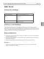
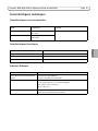
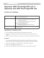
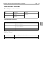
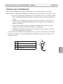
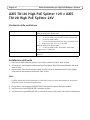
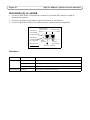
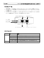
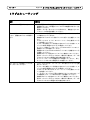
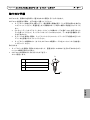
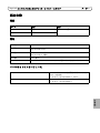
INSTALLATION GUIDE
AXIS T8126 High PoE Splitter 12V
FRANÇAIS
AXIS T8128 High PoE Splitter 24V
ENGLISH
AXIS T8123 High PoE Midspan 1-port
DEUTSCH
ITALIANO
ESPAÑOL
日本語
Safety information (for AXIS High PoE
Midspan only)
Technical support (for AXIS High PoE Midspan
and Splitters)
Installation and removal of the AXIS High PoE
Midspan must be carried out by qualified
personnel only.
Should you require technical assistance, please contact
your Axis reseller. If your questions cannot be answered
immediately, the reseller will forward your queries
through the appropriate channels to ensure rapid
response. If you are connected to the Internet, you can:
• AC Power Cable Set:
• The power cable must have regulatory agency
approval for the specific country in which it is used
(for example, UL, CSA, VDE).
• The power cable must be a three-conductor type
(two current carrying conductors; one ground
conductor) terminated on one end by an IEC 60320
appliance coupler (for connection to the AXIS High
PoE Midspan), and on the other end by a plug
containing a ground (earthing) contact.
• The power cable must be rated for a minimum of
250Vac RMS operation, with a minimum rated
current capacity of 5 amps (or a minimum wire
gauge of 18 AWG (0.75mm2).
• Note: AXIS High PoE Midspans installed in Australia
require power cables with a minimum wire gauge of
16 AWG (1.0 mm2).
• The AC wall socket-outlet must be near the AXIS High
PoE Midspan and easily accessible. You can remove AC
power from the AXIS High PoE Midspan by
disconnecting the AC power cable from either the wall
socket-outlet or the AXIS High PoE Midspan appliance
coupler.
• The AXIS High PoE Midspan data and data/power
interfaces are qualified as SELV (Safety Extra-Low
Voltage) circuits according to IEC 60950. These
interfaces can only be connected to SELV interfaces on
other equipment.
WARNING!
• Read the installation instructions before connecting
the AXIS High PoE Midspan to its power source.
• Follow basic electricity safety measures whenever
connecting the AXIS High PoE Midspan to its power
source.
• A voltage mismatch can cause equipment damage
and may pose a fire hazard. If the voltage indicated
on the label is different from the power outlet
voltage, do not connect the AXIS High PoE Midspan
to this power outlet.
• This product relies on the building installation for
short-circuit (over current) protection. Ensure that a
fuse or circuit breaker no larger than 120 VAC, 3A.
U.S. (240 VAC, 1.5A international) is used on the
phase conductor.
• The AXIS High PoE Midspan "Data In" and "Data &
Power Out" ports are shielded RJ-45 data sockets.
They cannot be used as Plain Old Telephone Service
(POTS) telephone sockets. Only RJ-45 data
connectors may be connected to these sockets.
Notice:
In keeping with its policy to improve products, as new
technology, components, software, and firmware
become available, Axis reserves the right to change
specifications without prior notice.
• Download user documentation
• Find answers to resolved problems in the FAQ database
• Search by product, category, or phrases
• Report problems to Axis support by logging in to your
private support area
• Visit Axis Support at www.axis.com/techsup/
Electromagnetic Compatibility (EMC)
This equipment generates, uses and can radiate radio
frequency energy and, if not installed and used in
accordance with the instructions, may cause harmful
interference to radio communications. However, there is
no guarantee that interference will not occur in a
particular installation.
If this equipment does cause harmful interference to
radio or television reception, which can be determined
by turning the equipment off and on, the user is
encouraged to try to correct the interference by one or
more of the following measures: Re-orient or relocate
the receiving antenna. Increase the separation between
the equipment and receiver. Connect the equipment to
an outlet on a different circuit to the receiver. Consult
your dealer or an experienced radio/TV technician for
help. Shielded (STP) network cables must be used with
this unit to ensure compliance with EMC standards.
USA - This equipment has been tested and found to
comply with the limits for a Class B computing device
pursuant to Subpart B of Part 15 of FCC rules, which are
designed to provide reasonable protection against such
interference when operated in a commercial
environment. Operation of this equipment in a
residential area is likely to cause interference, in which
case the user at his/her own expense will be required to
take whatever measures may be required to correct the
interference.
Canada - This Class B digital apparatus complies with
Canadian ICES-003.
Europe -
This digital equipment fulfills the
requirements for radiated emission according to limit B
of EN55022, and the requirements for immunity
according to EN55024 residential and commercial
industry.
Japan - This is a class B product based on the standard
of the Voluntary Control Council for Interference from
Information Technology Equipment (VCCI). If this is used
near a radio or television receiver in a domestic
environment, it may cause radio interference. Install and
use the equipment according to the instruction manual.
Australia - This electronic device meets the
requirements of the Radio communications
(Electromagnetic Compatibility) Standard AS/NZS
CISPR22.
WEEE Directive
The European Union has enacted a Directive
2002/96/EC on Waste Electrical and Electronic
Equipment (WEEE Directive). This directive is
applicable in the European Union member
states.
The WEEE marking on this product (see right) or its
documentation indicates that the product must not be
disposed off together with household waste. To prevent
possible harm to human health and/or the environment,
the product must be disposed off in an approved and
environmentally safe recycling process. For further
information on how to dispose off this product correctly,
contact the product supplier, or the local authority
responsible for waste disposal in your area.
Business users should contact the product supplier for
information on how to dispose off this product correctly.
This product should not be mixed with other commercial
waste. For more information, visit
www.axis.com/techsup/
AXIS T8123 High PoE Midspan 1-port is identical to the
Microsemi PD-9001G-40 (1-port High Power over
Ethernet Midspan).
AXIS T8126 High PoE Splitter 12V and AXIS T8128 High
PoE Splitter 24V are identical to the Microsemi
PD-AS-701/12 and PD-AS-701/24 (Power over Ethernet
Active Splitter).
High PoE Midspan and Splitters Installation Guide
Page 5
AXIS T8123
Package contents
AXIS T8123 High PoE Midspan 1-port
Power cable (region specific)
Europe
UK
USA
Japan
Australia
Printed material
Installation guide
Warranty document
Functions and features
The AXIS T8123 High PoE Midspan 1-port injects 55V DC power into the spare pairs of the Ethernet
cabling. It maintains IEEE802.3af specification parameters while doubling the output power. These
power levels allowed a new range of Ethernet-based applications such as PTZ Cameras to use the
High PoE Midspan.
Preliminary steps
•
•
•
Ensure AC power is applied to the AXIS T8123, using an operational AC cable with appropriate ground connection.
Ensure that output Ethernet cable is connected to the Data & Power Out port.
Verify that a power ready Ethernet compatible device or splitter is connected.
Note:
Do not use a cross over cable between the AXIS T8123 output port and the powered device.
ENGLISH
AXIS High PoE Midspan
Page 6
High PoE Midspan and Splitters Installation Guide
Installation
1. Connect the AXIS T8123 to an AC outlet (100-240 VAC), using a standard power cable.
2. Connect the unit Data In jack (input) to your remote Ethernet network switch using an Ethernet
cable.
3. Connect the Data & Power Out jack (output) to your Axis splitter or camera, using an Ethernet
cable.
Data and Power out
Data in
Port connectivity
indicator
AC Input connectivity
indicator
Output port
Camera/splitters
Input port
Ethernet
Indicators
LED
Color
Indication
Port
Unlit
No camera connected
Flashing
Power overload or other input voltage error
Steady green
Camera connected, normal behavior
Green 1 Hz blinking
Over current or short circuit condition on the port
AC input
Green 4 Hz blinking
PSE input voltage out of range or other internal fault
Steady green
AC power connected
High PoE Midspan and Splitters Installation Guide
Page 7
Specifications
Environmental
Temperature
Humidity
Operating
-10 to 55°C
14 to 131°F
10 to 90% (no condensation allowed)
Storage
-40 to 70°C
-24 to 158°F
ENGLISH
Mode
Electrical
Input voltage
100 -240VAC (50-60 Hz)
Input current
1.5A (max)
Maximum Available Output Power
30W
Nominal Output Voltage
55V DC
Ethernet interface
Input (Data In):
RJ45 female socket
Ethernet 10/100/1000Base-T
Output (Data & Power Out):
RJ45 female socket
Ethernet 10/100/1000Base-T, plus 55 VDC
Wiring
Data provided over pairs 1/2 and 3/6 for 10/100 Ethernet, over all four pairs
for Gigabit Ethernet
Power provided over spare pairs 4/5(+) and 7/8(-).
Network cable
Category 5 (or higher), foiled twisted-pair (FTP) cable recommended.
Page 8
High PoE Midspan and Splitters Installation Guide
Troubleshooting
Symptom
Corrective steps
Midspan does not power up
1.
2.
3.
A port indicator is not lit and the PD 1.
(powered device) does not operate 2.
3.
4.
5.
6.
7.
8.
The end device operates, but there is 1.
no data link
2.
3.
4.
5.
Verify that an approved power cable is used.
Verify that the voltage at the power inlet is between 100 and
240V AC.
Remove and re-apply power to the device and check the
indicators during power up sequence.
The Midspan did not detect a PD; and the port is not enabled.
Verify that the PD is designed for PoE operation.
Verify that you are using a standard Category 5/5e/6, straightwired cable, with four pairs.
If there is an external PoE device is connected, replace it to verify
that it is functioning properly.
Ensure that the input Ethernet cable is connected to the Data In
port.
Verify that the PD is connected to the Data & Power port.
Try to reconnect the same PD into a different Midspan. If it works,
there is probably a faulty port or RJ-45 connection.
Verify that there is no shortcut over any of the twisted pair cables
or over the RJ45 connectors.
Verify that the port indicator on the front panel is continuously
lit.
If an external PoE device is in use, replace it with a known good
PoE device.
Verify that for this link, you are using standard UTP/FTP Category
5 straight (non-crossover) cabling, with all four pairs.
Verify that the Ethernet cable length is less than 100 meters (333
feet) from the Ethernet source to the powered device.
Try to reconnect the same PD into a different Midspan. If it works,
there is probably a faulty port or RJ-45 connection.
High PoE Midspan and Splitters Installation Guide
Page 9
Mounting instructions
The AXIS T8123 may be wall or bench mounted using the rear side holes.
Note the following before mounting the AXIS T8123 to a fixed location:
•
1. Install two screws vertically at a distance of 9.17 cm (3.61”) on the wall or shelf.
2. Align the AXIS T8123 mounting slots to capture
the surface screws.
A
A
5.8 to 7.0 mm (0.23" to 0.27")
B
2.0mm (0.08")
C
1.5mm to 2.5 mm (0.059" to
0.098")
D
3.0 mm (0.12")
B
C
D
ENGLISH
Do not cover the midspan or block the airflow to the product with any foreign object. Keep
the midspan away from excessive heat and humidity, and free from vibration and dust.
• Ensure that the cable length from the Ethernet network source to your Axis video product
does not exceed 100 meters (333 feet). The midspan is not a repeater and does not amplify
the Ethernet data signal.
• Use a splitter if desired, but ensure that the splitter is connected close to your Axis video
product and not to the Midspan.
• There is no "on-off" switch; simply plug the AXIS T8123 into an AC power outlet.
To mount:
Page 10
High PoE Midspan and Splitters Installation Guide
AXIS T8126 High PoE Splitter 12V and AXIS
T8128 High PoE Splitter 24V
Package contents
AXIS High PoE Splitter
AXIS T8126 High PoE Splitter 12V
AXIS T8128 High PoE Splitter 24V
Power adapter cable
AXIS T8126 High PoE Splitter 12V:
•
1 x cable for AXIS 213 PTZ, AXIS 214 PTZ, AXIS 215 PTZ
•
1 x cable for AXIS 225FD
•
1 x cable for AXIS cameras with PS-K connector
•
length for each cable - 1m / 3.33 feet
AXIS T8128 High PoE Splitter 24V:
Printed material
•
1 x cable for AXIS 231D+, AXIS 232D+, AXIS 233D
•
length: 5m / 16.65 feet
Installation guide
Installation
1. Place the High PoE splitter as close as possible to the Axis video product.
2. Connect the Ethernet cable from the Data Out port to the Ethernet input of the Axis video
product.
3. Connect the power adapter cable to the DC Out port of the splitter to the power input of your
Axis video product.
Note:
For AXIS 225FD, AXIS 231D+/AXIS 232D+, and AXIS 233D, follow the Installation Guide of
the product (also available at www.axis.com/techsup)
4. Connect the Ethernet cable from the AXIS T8123 High PoE Midspan to the PoE In port of the
splitter.
5. Verify that PWR IN LED turns green.
6. Verify that PWR Out LED turns green and that your Axis network camera is powered up.
High PoE Midspan and Splitters Installation Guide
Page 11
Specifications
Environmental
Temperature
Humidity
Operating
0 - 40°C
32 to 104°F
10 to 90% (no condensation allowed)
Storage
-20 to 70°C
-4 to 158°F
ENGLISH
Mode
Electrical
Input voltage
44-57 VDC
Output voltage
12 VDC for AXIS T8126
24 VDC for AXIS T8128
Output current
2 A max for AXIS T8126
1 A max for AXIS T8128
Output power
24 W max
Output connector
DC barrel connector 6.4x2.5 mm (0.252x0.098"); with '+' centered
Ethernet interface
Input (Data In):
RJ45 female socket, with DC voltage on wire pairs 7/8
and 4/5.
Ethernet 10/100/1000Base-T, plus 48 VDC
Output (Data & Power Out):
RJ45 female socket
Ethernet 10/100/1000Base-T
Injecteur AXIS High PoE et Séparateur Guide d'installation
Page 13
AXIS T8123
Contenu de l´emballage
Injecteur AXIS T8123 High PoE 1 port
Câble d´alimentation (Dépend du
pays)
Europe
Royaume-Uni
USA
Japon
Australie
Documentation imprimée
Guide d´installation
Document de garantie
Fonctions et caractéristiques
L´injecteur AXIS T8123 High POE 1 port injecte une alimentation de 55V DC dans les paires
disponibles du cable Ethernet. La norme IEEE802.3af est maintenue tout en doublant la puissance
de sortie. Ces niveaux de puissance permettent de nouvelles possibilités comme l´alimentation de
cameras PTZ AXIS par l´intermérdiaire d´injecteurs High PoE.
Étapes préliminaires
•
•
•
Vérifiez que l'injecteur AXIS T8123 est raccordé à un câble CA en bon état de fonctionnement
et correctement mis à la terre.
Vérifiez que le câble Ethernet de sortie est branché sur le port Data & Power Out (données et
d'alimentation de sortie).
Vérifiez qu'un périphérique compatible Ethernet prêt à être branché est connecté.
Remarque :
N'utilisez pas de câble simulateur de modem entre le port de sortie de l'injecteur AXIS
T8123 et le périphérique de charge.
FRANÇAIS
Injecteur AXIS High PoE
Page 14
Injecteur AXIS High PoE et Séparateur Guide d'installation
Installation de l'injecteur
1. Branchez l'injecteur AXIS T8123 sur une prise CA (100-240 V CA), à l'aide d'un câble ordinaire.
2. Branchez le connecteur Data IN (Données d´entrée) de l´injecteur sur le commutateur réseau
Ethernet via un câble Ethernet.
3. Branchez le connecteur Data & Power (Données et alimentation de sortie) de l´injecteur sur le
séparateur (PoE IN) ou sur la caméra via un câble Ethernet.
Données et
alimentation de sortie
Données d’entrée
Indicateur de
connexion du port
Indicateur de
connexion d’entrée CA
Port de sortie
Port d’entrée
Câble de cat. 5
Terminal
Ethernet
Indicateurs
Témoin
Couleur
Indication
Indicateur
Éteint
Aucune caméra connectée
Entrée CA
Clignotement
Surcharge de l’alimentation ou autre erreur de tension d’entrée
Vert
Caméra connectée, fonctionnement normal
Vert continu
Alimentation CA connectée
Injecteur AXIS High PoE et Séparateur Guide d'installation
Page 15
Caractéristiques techniques
Caractéristiques environnementales
Mode
Température
Humidité
En fonctionnement
-10 à 55°C
32 à 104°F
10 à 90% (condensation non autorisée)
En stockage
-40 à 70°C
-24 à 158°F
Caractéristiques électriques
100 à 240V CA (50-60 Hz)
Courant d'entrée
1.5A (max)
Puissance de sortie disponible maximum
30W
Tension de sortie nominale
52 à 56V CC
Interface Ethernet
Entrée (données d'entrée) :
Ethernet 10/100/1000Base-T; Connecteur femelle RJ45
Sortie (données et alimentation de
sortie) :
Ethernet 10/100/1000Base-T,
55 V CC; Connecteur femelle RJ45
Câblage
Donnée envoyée sur les paires 1/2 et 3/6 pour l´Ethernet 10/100, et
sur les quatres paires pour l´Ethernet GigaBit
avec tension CC sur les paires
de fils 7-8 et 4-5
Câble réseau
Catégorie 5 (ou plus)
Câble blindé torsadé (FTP) recommandé
FRANÇAIS
Tension d'entrée
Page 16
Injecteur AXIS High PoE et Séparateur Guide d'installation
Résolution des problèmes
Symptôme
Correction
L'injecteur ne se met pas sous tension.
1.
2.
3.
Un indicateur de port est éteint et le 1.
périphérique ne fonctionne pas.
2.
3.
4.
5.
6.
7.
8.
Le périphérique final
fonctionne, mais il
n'y a pas de liaison
de données.
1.
2.
3.
4.
5.
Vérifiez qu'un cordon d'alimentation approuvé est utilisé.
Vérifiez que la tension à l'arrivée se situe entre 100 et 240 V CA.
Mettez l'injecteur hors tension et rallumez-le en vérifiant les
indicateurs pendant la mise sous tension.
L'injecteur n'a pas détecté de périphérique. Le port est donc
désactivé.
Vérifiez que le périphérique prend en charge la technologie PoE.
Vérifiez que vous utilisez un câble droits ordinaire de catégorie 5/
5e/6, à quatre paires.
Si un dispositif PoE externe est utilisé, remplacez-le pour vous
assurer qu'il fonctionne correctement.
Vérifiez que le câble Ethernet d'entrée est branché sur le port de
données d'entrée.
Vérifiez que le périphérique est branché sur le port de données et
d'alimentation.
Essayez de rebrancher le périphérique sur un injecteur différent.
S'il fonctionne, il est probable que le port ou le connecteur RJ-45
soit défectueux.
Vérifiez qu'il n'y a pas de court-circuit sur les câbles à paires
torsadées ni sur les connecteurs RJ45.
Vérifiez que l'indicateur de port à l'avant de l'appareil est allumé
en continu.
Si un dispositif PoE externe est utilisé, remplacez-le par un
séparateur que vous savez en bon état de fonctionnement.
Vérifiez que, pour cette liaison, vous utilisez un cable droit UTP/
FTP ordinaire de catégorie 5 (et non un cable simulateur de
modem), avec les quatre paires.
Vérifiez que le câble Ethernet ne fait pas plus de 100 mètres de
long entre la source Ethernet et le terminal distant.
Essayez de rebrancher le périphérique sur un injecteur différent. Si
cela fonctionne, il est probable que le connecteur RJ-45 soit
défectueux.
Injecteur AXIS High PoE et Séparateur Guide d'installation
Page 17
Instructions de montage
L'injecteur AXIS T8123 peut être fixé au mur ou sur une surface plate à l'aide des trous situés au dos
de l'appareil.
Veuillez prendre note de ce qui suit avant de poser l'injecteur AXIS T8123 à un endroit fixe :
•
A
A
5.8 to 7.0 mm (0.23" to 0.27")
B
2.0mm (0.08")
C
1.5mm to 2.5 mm (0.059" to
0.098")
D
3.0 mm (0.12")
B
C
D
FRANÇAIS
Ne recouvrez pas l'injecteur PoE et ne bloquez pas son système d'aération par des corps
étrangers. Conservez l'injecteur AXIS T8123 à l'abri des excès de la chaleur et de l'humidité,
des vibrations et de la poussière.
• Veillez à ce que la longueur de câble entre la source du réseau Ethernet et le terminal ne
dépasse pas 100 mètres. Le PoE n'est pas un répéteur et il n'amplifie pas le signal des données Ethernet.
• Utilisez un séparateur si vous le souhaitez, en veillant à ce qu'il soit branché à proximité du
terminal et non sur l'injecteur.
• Il n'y a pas d'interrupteur Marche/Arrêt. Il suffit donc de brancher l'injecteur AXIS T8123 sur
une prise de courant CA pour le mettre en marche.
1. Installez deux vises verticallement à une distance de 9.17 cm sur le mur ou une armoire
2. Alignez l´ AXIS T8123 aux visses pour le fixer.
Page 18
Injecteur AXIS High PoE et Séparateur Guide d'installation
Séparateur AXIS T8126 High POE 12V et
Séparateur Axis AXIS T8128 High POE 24V
Contenu de l´emballage
Séparateur Axis High POE
Séparateur AXIS T8126 High POE 12V
Séparateur AXIS T8128 High POE 24V
Adaptateur câble d´alimentation
Séparateur 12V AXIS T8126 High PoE
• 1 x câble pour AXIS 213 PTZ, AXIS 214 PTZ, AXIS 215 PTZ
• 1 x câble pour AXIS 225FD
• 1 x câble pour caméra AXIS utilisant l´alimentation PS-K
• Longueur de chaque câble : 1 mètre
Séparateur 24V AXIS T8128 High PoE
• 1 x câble pour AXIS 231D+, AXIS 232D+, AXIS 233D
• Longueur du câble : 5 mètres
Documentation imprimée
Guide d´installation
Document de garantie
Installation du sépateur PoE :
1. Placez le séparateur Axis High POE le plus prêt possible de la camera Axis
2. Connectez le cable Ethernet du port Data Out (sortie Donnée) vers le port Ethernet de la
camera.
3. Connectez le cable d´alimentation du séparateur sur le connecteur d´alimentation de la camera.
Remarque :
Pour les produits AXIS 225FD, AXIS 231D+/ AXIS 232D+, et AXIS 233D, veuillez suivre les
instructions dans le guide d´installation (également disponible sur www.axis.com/techsup)
4. Connectez le câble Ethernet de l´AXIS T8123 sur le port POE IN du séparateur.
5. Verifiez que la LED PWR IN est allumée en vert.
6. Vérifiez que la LED PWR OUT est allumée en vert et que la camera AXIS est alimentée.
Injecteur AXIS High PoE et Séparateur Guide d'installation
Page 19
Caractéristiques techniques
Caractéristiques environnementales
Mode
Température
Humidité
En fonctionnement
0 à 40°C
32 à 104°F
10 à 90% (condensation non
autorisée)
En stockage
-20 à 70°C
-4 à 158°F
Caractéristiques électriques
44 à 57 V CC
Tension de sortie
12 V DC pour AXIS T8123
24 V DC pour AXIS T8128
Courant de sortie
2 A max pour AXIS T8126
1 A max pour AXIS T8128
Puissance de sortie
24 W max
Connecteur de sortie
Connecteur 6.4x2.5 mm
Interface Ethernet
Entrée (P0E IN):
Ethernet 10/100/1000Base-T, 48 V CC;
Connecteur femelle RJ45
Sortie (Data Out) :
Ethernet 10/100/1000Base-T; Connecteur femelle RJ45
FRANÇAIS
Tension d´entrée
High Poe Midspan und Splitters Installationsanleitung
Seite 21
AXIS T8123
Lieferumfang
AXIS High PoE Midspan
AXIS T8123 High PoE Midspan 1-port
Stromkabel (landesspezifisch)
Europa
UK
USA
Japan
Australien
Gedruckte Dokumente
Installationsanleitung
Garantieerklärung
Funktionen und Merkmale
Vorbereitende Schritte
•
•
•
Stellen Sie sicher, dass Netzstrom über ein einsatzbereites geerdetes Stromkabel am
AXIS T8123 anliegt.
Stellen Sie sicher, dass das ausgehende Ethernet-Kabel am Anschluss Date & Power Out
angeschlossen ist.
Prüfen Sie, ob ein stromaufnahmefähiges, Ethernet-kompatibles Gerät angeschlossen
ist.
Hinweis: Verwenden Sie kein gekreuztes Netzwerkkabel zwischen dem Ausgang am AXIS T8123 und dem
zu betreibenden Gerät!
DEUTSCH
Der AXIS T8123 speist 55V DC Spannung in in die Ersatzpaare des Ethernet Kabel ein. Er behält
IEEE802.3af spezifische Parameter bei aber verdoppelt die Ausgangsleistung. Diese Leistung
eröffnet neue Möglichkeiten für Ethernet basierte Anwendungen - wie z.B. das Betreiben von PTZ
Kameras über den AXIS T8123.
Seite 22
High Poe Midspan und Splitters Installationsanleitung
Installation
1. Schließen Sie den AXIS T8123 über ein Standardnetzkabel an eine Netzsteckdose (100-240 V
AC) an.
2. Verbinden Sie die Buchse Data In (Dateneingang) am Gerät mit dem Patchpanel oder Switch.
3. Verbinden Sie die Gerätebuchse Data & Power Out (Daten- und Stromausgang) mit Ihrer Axis
Kamera oder Ihrem Axis Splitter.
Data & Power out
Data in
(Daten- und Stromausgang) (Dateneingang)
Anschlussanzeige
Netzeingangsanzeige
CAT 5-Kabel
Ausgangsanschluss
Endgerät
Eingangsanschluss
Ethernet
Anzeigen
LED
Port
Netzeingang
Farbe
Bedeutung
Leuchtet nicht
Keine Kamera angeschlossen
Blinkt
Stromüberlast oder anderer Fehler bei der Eingangsspannung
Grün
Kamera verbunden, normales Verhalten
Konstant grün
Netzstrom verbunden
High Poe Midspan und Splitters Installationsanleitung
Seite 23
Technische Daten
Umgebungsbedingungen
Modus
Temperatur
Luftfeuchtigkeit
Betrieb
-10 bis 55°C
32 bis 131°F
10 bis 90%, (nicht kondensierend)
Lagerung
-40 bis 70°C
-24 bis 158°F
Elektrische Daten
Eingangsspannung
100 bis 240V AC (50-60 Hz)
Eingangsstrom
1.5A (max)
Maximal verfügbare Ausgangsleistung
30W
Ausgangsnennspannung
55V DC
DEUTSCH
Ethernetanschlüsse
Eingang (Data In):
Ethernet 10/100/1000Base-T; RJ 45-Buchse
Ausgang (Data & Power out):
Ethernet 10/100/1000Base-T, plus 55 V DC; RJ 45-Buchse
Verkabelung
Datenleitung über Adernpaare 1/2 und 3/6 für 10/100 Mbit Ethernet, alle
vier Paare bei Gigabit Ethernet.
Gleichspannung über die Adernpaare 7/8 und 4/5
Netzwerkkabel
Kategorie 5 (oder höher)
Geschirmte Netzwerkkabel empfohlen.
Seite 24
High Poe Midspan und Splitters Installationsanleitung
Fehlerbehebung
Symptom
Abhilfemaßnahmen
Midspan bekommt keinen Strom
1. Prüfen Sie, ob ein zugelassenes Netzkabel verwendet wird.
2. Prüfen Sie, ob die Spannung am Stromeingang zwischen 100 und
240 V AC liegt.
3. Ziehen Sie das Stromkabel vom Gerät ab und stecken Sie es erneut
ein und prüfen Sie dann die Anzeigen beim Hochfahren.
Anschlussanzeige leuchtet nicht,
und das zu versorgende Gerät
funktioniert nicht
1.
2.
3.
4.
5.
6.
7.
8.
Das Endgerät funktioniert, aber es
besteht keine Datenverbindung
1.
2.
3.
4.
5.
Der Midspan hat kein zu versorgendes Gerät erkannt, und deshalb
ist der Anschluss nicht aktiviert.
Prüfen Sie, ob das zu versorgende Gerät für den PoE Betrieb
geeignet ist.
Prüfen Sie, ob Sie ein 1:1-verdrahtetes Standardkabel der
Kategorie 5/5e/6 mit vier Paaren verwenden.
Falls ein externes PoE-Gerät angeschlossen ist, ersetzen Sie diesen,
um sicherzustellen, dass dieser ordnungsgemäß funktioniert.
Stellen Sie sicher, dass das Eingangs-Ethernet-Kabel an den
Anschluss Data In (Dateneingang) angeschlossen ist.
Prüfen Sie, ob das zu versorgende Gerät an den Anschluss "Data &
Power" (Daten und Strom) angeschlossen ist.
Versuchen Sie, dasselbe zu versorgende Gerät an einen anderen
Midspan anzuschließen. Wenn es funktioniert, ist wahrscheinlich
ein Anschluss oder die RJ-45-Verbindung fehlerhaft.
Stellen Sie sicher, dass kein Kurzschluss zwischen den TwistedPair-Kabeln oder an den RJ-45-Steckern besteht..
Prüfen Sie, ob die Anschlussanzeige (Port) an der Vorderseite
ununterbrochen leuchtet.
Falls ein externes PoE-Gerät verwendet wird, ersetzen Sie diesen
durch ein PoE-Gerät, von dem Sie wissen, dass dieses
ordnungsgemäß funktioniert.
Vergewissern Sie sich, dass Sie für diese Verbindung 1:1verdrahtete (nicht gekreuzte) UTP/FTP-Standardkabel der
Kategorie 5 oder höher mit vier Paaren verwenden.
Stellen Sie sicher, dass die Länge des Ethernet-Kabels 100 Meter
von der Ethernet-Quelle zum Endgerät nicht überschreitet.
Versuchen Sie, dasselbe Endgerät an einen anderen Midspan
anzuschließen. Wenn es funktioniert, ist wahrscheinlich ein
Anschluss oder die RJ-45-Verbindung fehlerhaft..
High Poe Midspan und Splitters Installationsanleitung
Seite 25
Montageanweisungen
Der AXIS T8123 kann mithilfe der rückseitigen Löcher entweder an der Wand oder an einer
horizontalen Fläche angebracht werden.
Beachten Sie vor der Montage des AXIS T8123 bitte Folgendes:
•
Decken Sie den AXIS T8123 nicht ab bzw. versperren Sie den Luftstrom zum Gerät nicht
mit Fremdkörpern. Halten Sie den AXIS T8123 von Wärmequellen und Feuchtigkeit fern
und setzen Sie ihn weder Vibrationen noch Staub aus.
• Stellen Sie sicher, dass die Kabellänge von der Ethernet-Netzwerkquelle zum Endgerät
100 Meter nicht überschreitet. Der AXIS T8123 ist kein Repeater und verstärkt damit
das Datensignal der Ethernet-Verbindung nicht.
• Verwenden Sie, falls gewünscht, einen Splitter; vergewissern Sie sich, dass der Splitter
in der Nähe des Endgeräts sitzt.
• Es ist kein Netzschalter vorgesehen; schließen Sie den AXIS T8123 einfach an eine
Netzstromquelle an.
1. Bringen Sie zwei Schrauben mit einem vertikalen Abstand von 9.17 cm (3.61") an einer Wand
oder einer horizontalen Fläche an.
2. Schieben Sie den AXIS T8123 mit den Montageschlitzen über die Schrauben.
5.8 bis 7.0 mm (0.23" to 0.27")
B
2.0mm (0.08")
C
1.5mm bis 2.5 mm (0.059" a 0.098")
D
3.0 mm (0.12")
DEUTSCH
A
A
B
C
D
Seite 26
High Poe Midspan und Splitters Installationsanleitung
AXIS T8126 High PoE Splitter 12V e AXIS
T8128 High PoE Splitter 24V
Lieferumfang
AXIS High PoE Splitter
AXIS T8126 High PoE Splitter 12V
AXIS T8128 High PoE Splitter 24V
Stromadapterkabel
AXIS T8126 High PoE Splitter 12V:
• 1 x Kabel für AXIS 213 PTZ, AXIS 214 PTZ, AXIS 215 PTZ
• 1 x Kabel für AXIS 225FD
• 1 x Kabel für AXIS Kameras mit PS-K Anschluss
• Länge der Kabel: 1m / 3.33 Fuß
AXIS T8128 High PoE Splitter 24V:
• 1 x Kabel für AXIS 231D+, AXIS 232D+, AXIS 233D
• Länge: 5m / 16.65 Fuß
Gedruckte Dokumente
Installationsanleitung
Garantieerklärung
Installieren des Gerätes
1. Platzieren Sie den AXIS High PoE Splitter so nah wie möglich am AXIS Gerät.
2. Verbinden Sie das Ethernet Kabel vom Data Out Anschluss mit dem Ethernet Anschluss der Axis
Kamera.
3. Verbinden Sie das Stromadapterkabel mit dem DC Anschluss des Splitters und dem
Stromeingangs des Axis Geräts.
Beachten Sie: Bei AXIS 225FD, AXIS 231D+/AXIS 232D+ und AXIS 233D folgen Sie bitte den
Anweisungen im Installationshandbuch des Geräts (ebenfalls verfügbar über www.axis.com/
techsup)
4. Verbinden Sie den AXIS T8123 Midspan über ein Ethernet Kabel mit dem Splitter.
5. Stellen Sie sicher, dass die PWR IN LED grün leuchtet.
6. Stellen Sie sicher, dass die PWR Out LED grün leuchtet und dass Ihr Axis Gerät korrekt startet.
High Poe Midspan und Splitters Installationsanleitung
Seite 27
Technische Daten
Umgebungsbedingungen
Modus
Temperatur
Luftfeuchtigkeit
Betrieb
0 bis 40°C
32 bis 104°F
10 bis 90%, (nicht kondensierend)
Lagerung
-20 bis 70°C
-4 bis 158°F
Elektrische Daten
44 bis 57 V DC
Ausgangsspannung
12 VDC für AXIS T8126
24 VDC für AXIS T8128
Ausgangsstrom
2 A max. für AXIS T8126
1 A max. für AXIS T8128
Ausgangsleistung
24 W max.
Ausgangsanschluss
DC Hohlstecker 6.4x2.5 mm (0.252x0.098"); mit '+' innen.
Ethernet Anschluss
Eingang (POE IN):
Ethernet 10/100/1000Base-T, plus 48 V DC; RJ 45-Buchse
Gleichspannung an Aderpaaren 7/8 und 4/5
Ausgang (Data Out):
Ethernet 10/100/1000Base-T; RJ 45-Buchse
DEUTSCH
Eingangsspannung
Guida d'Installazione per High PoE Midspan e Splitters
Pagina 29
AXIS T8123
Contenuto della confezione
AXIS High PoE Midspan
AXIS T8123 High PoE Midspan 1-porta
Cavo di alimentazione (diverso
a seconda del Paese)
Europa
UK
USA
Giappone
Australia
Materiale cartaceo
Guida all'installazione
Garanzia
Funzioni e caratteristiche
L'AXIS T8123 High PoE Midspan ad 1-porta trasmette un'alimentazione di 55V CC negli
accoppiamenti di ricambio del cablaggio di Ethernet. É in grado di mantenere i parametri dello
standard IEEE802.3af e raddoppiare l'alimentazione in uscita.
Questi livelli di alimentazione permettono di ampliare le applicazioni basate su Ethernet, ad
esempio le telecamere PTZ, utilizzabili con l'High PoE Midspan.
Operazioni preliminari
•
•
Verificare che l'AXIS T8123 sia alimentato con corrente CA mediante un cavo CA attivo
con adeguata connessione di messa a terra.
Verificare che il cavo Ethernet di uscita sia collegato alla porta dei dati e
dell'alimentazione.
Verificare che il dispositivo compatibile con Ethernet da alimentare sia collegato.
Nota
Non usare cavi incrociati tra la porta di uscita dell'AXIS High PoE Midspan e il dispositivo di carico.
ITALIANO
•
Pagina 30
Guida d'Installazione per High PoE Midspan e Splitters
Installazione dell'unità
1. Collegare l'AXIS High PoE Midspan a una presa CA (100-240 VCA) utilizzando un cavo di
alimentazione standard.
2. Collegare la presa jack di ingresso Data In (Ingresso dati) allo switch di rete Ethernet, usando un
cavo di rete Ethernet.
3. Collegare la presa jack di uscita Data & Power Out (Uscita dati e alimentazione) all'unitá Axis
oppure allo splitter, usando un cavo di rete Ethernet.
Uscita dati
e alimentazione
Ingresso dati
Indicatore dello
stato di connessione
della porta
Indicatore dello
stato di connessione
dell'ingresso CA
Porta di
uscita
Cavo CAT 5
Porta di
ingresso
Terminale Ethernet
Indicatori luminosi
LED
Indicatore
Ingresso CA
Colore
Indicazione
Spento
Nessuna telecamera connessa
Lampeggiante
Sovraccarico di alimentazione o altro errore nella tensione di ingresso
Verde
Telecamera connessa, condizione normale
Verde fisso
Connessione all’alimentazione CA attiva
Guida d'Installazione per High PoE Midspan e Splitters
Pagina 31
Dati tecnici
Specifiche ambientali
Modalità
Temperatura
Umidità
Di esercizio
da -10 a 55°C
da 32 a 104°F
10 to 90% (senza condensa)
Immagazzinaggio
da -20 a 70°C
da -4 a 158°F
Specifiche elettriche
Tensione in ingresso
100 -240VAC (50-60 Hz)
Corrente in ingresso
1.5A (max)
Potenza di uscita massima disponibile
30W
Tensione nominale in uscita
55V DC
Interfaccia Ethernet
Presa femmina RJ 45
Ethernet 10/100/1000Base-T
Uscita (dati e alimentazione)
Presa femmina RJ 45
Ethernet 10/100/1000Base-T, e 55 VCC
Collegamenti
Dati forniti dalle coppie 1/2 e 3/6 per 10/100 Ethernet, mentre per il
Gigabit Ethernet vengono usate tutte le coppie.
Presa femmina RJ 45 con tensione CC sulle coppie di fili 7/8 e 4/5.
Cavo di rete
Categoria 5 (o superiore)
cavo FTP (foiled twisted-pair) raccomandato.
ITALIANO
Ingresso (dati)
Pagina 32
Guida d'Installazione per High PoE Midspan e Splitters
Risoluzione dei problemi
Problema
Azione correttiva
Il Midspan non si accende
1.
L'indicatore luminoso della porta
non si accende e il dispositivo
alimentato non funziona
1.
Verificare che il cavo di alimentazione utilizzato sia di tipo
approvato.
2. Verificare che la tensione di alimentazione in ingresso sia
compresa tra 100 e 240V CA.
3. Rimuovere e riapplicare l'alimentazione al dispositivo e osservare
gli indicatori luminosi durante la sequenza di avvio.
2.
3.
4.
5.
6.
7.
8.
Il dispositivo video terminale
funziona, ma i dati non vengono
trasmessi
1.
2.
3.
4.
5.
Il Midspan non è riuscito a rilevare un dispositivo alimentato e la
porta non è quindi abilitata.
Verificare che il dispositivo alimentato possa essere usato con la
tecnologia PoE.
Verificare che il cavo in uso sia un cavo diritto Cat. 5/5e/6
standard con quattro doppini.
Se è presente un dispositivo PoE esterno, sostituirlo per verificare
che funzioni correttamente.
Verificare che il cavo Ethernet sia collegato alla porta di ingresso
dati.
Verificare che il dispositivo alimentato sia collegato alla porta dati
e alimentazione.
Provare a collegare lo stesso dispositivo alimentato a un Midspan
diverso. Se funziona correttamente, è probabile che la porta o la
connessione RJ-45 sia difettosa.
Verificare che non ci siano cortocircuiti sui cavi a doppini
incrociati o sui connettori RJ45.
Verificare che l'indicatore luminoso della porta sul pannello
anteriore sia acceso fisso.
Se è in uso un dispositivo PoE esterno, sostituirlo con uno
funzionante.
Verificare che il cavo usato per il collegamento sia un cavo UTP/
FTP diritto Cat. 5 standard (non incrociato) con tutti e quattro i
doppini.
Verificare che la lunghezza del cavo di rete tra la presa Ethernet e
l'unitá terminale sia inferiore a 100 metri.
Provare a ricollegare lo stesso dispositivo alimentato a un Midspan
diverso. Se funziona correttamente, è probabile che la porta o la
connessione RJ-45 sia difettosa.
Guida d'Installazione per High PoE Midspan e Splitters
Pagina 33
Istruzioni per l'installazione
L'AXIS High PoE Midspan può essere montato a muro o su un piano tramite i fori sul retro.
Prima di montare l'AXIS High PoE Midspan in un'ubicazione fissa, prendere nota di quanto segue:
•
Non coprire l'AXIS High PoE Midspan né ostruire il flusso di aria con materiale estraneo.
Tenere il PoE Midspan lontano da calore e umidità eccessivi, nonché da vibrazioni e
polvere.
• Verificare che la lunghezza del cavo tra la presa di rete Ethernet e il morsetto non
superi i 100 metri. L'AXIS High PoE Midspan non è un ripetitore e non amplifica il
segnale dati Ethernet.
• Se necessario è possibile usare uno splitter, a condizione che tale splitter venga
collegato il più vicino possibile al terminale e non al Midspan.
• L'AXIS High PoE Midspan non dispone di un interruttore di accensione ed è quindi
sufficiente collegarlo a una presa CA.
1. Installare due viti verticalmente alla distanza di 9.17 cm (3.61") sulla parete o sullo scaffale.
2. Allineare lo scheletro montante dell'AXIS High PoE Midspan in modo che si incastri con la
superfice delle viti.
A
5.8 a 7.0 mm (0.23" to 0.27")
B
2.0mm (0.08")
C
1.5mm a 2.5 mm (0.059" a 0.098")
D
3.0 mm (0.12")
B
C
D
ITALIANO
A
Pagina 34
Guida d'Installazione per High PoE Midspan e Splitters
AXIS T8126 High PoE Splitter 12V e AXIS
T8128 High PoE Splitter 24V
Contenuto della confezione
AXIS High PoE Splitter
AXIS T8126 High PoE Splitter 12V
AXIS T8128 High PoE Splitter 24V
Adattatore del cavo di alimentazione
AXIS T8126 High PoE Splitter 12V:
• 1 x cavo per AXIS 213 PTZ, AXIS 214 PTZ, AXIS 215 PTZ
• 1 x cavo per AXIS 225FD
• 1 x cavo per telecamere AXIS che usano connettori PS-K
• lunghezza di ogni cavo: 1m / 3.33 piedi
AXIS T8128 High PoE Splitter 24V:
• 1 x cavo per AXIS 231D+, AXIS 232D+, AXIS 233D
lunghezza: 5m / 16.65 piedi
Materiale cartaceo
Guida all'installazione
Garanzia
Installazione dell'unità
1. Posizionare l'AXIS High PoE splitter il piú vicino possibile all'unitá video di Axis.
2. Connettere il cavo Ethernet dalla porta Data Out (Uscita Dati) all'entrata Ethernet dell'unitá
video di Axis.
3. Connettere il cavo di alimentazione della porta di uscita di alimentazione CC dello splitter
all'entrata di alimentazione dell'unitá video di Axis.
Nota
Per AXIS 225FD, AXIS 231D+/AXIS 232D+, e AXIS 233D, seguire la Guida all'Installazione del prodotto
(disponibile anche su www.axis.com/techsup)
4. Connettere il cavo Ethernet dall'AXIS T8123 alla porta d'ingresso PoE dello splitter.
5. Verificare che la spia PWR IN LED si accenda di verde.
6. Verificare che la spia PWR OUT LED si accenda di verde e che l'unitá video Axis sia alimentata.
Guida d'Installazione per High PoE Midspan e Splitters
Pagina 35
Dati tecnici
Specifiche ambientali
Modalità
Temperatura
Umidità
Di esercizio
0 - 40°C
32 - 104°F
10 to 90% (senza condensa)
Immagazzinaggio
-20 - 70°C
-4 - 158°F
Specifiche elettriche
Tensione d'entrata
Da 44 a 57 V CC
Tensione d'uscita
12 V CC for AXIS T8126
24 V CC for AXIS T8128
Corrente d'uscita
2A max per AXIS T8126
1A max per AXIS T8128
Uscita d'alimentazione
24 W max
Uscita connettore
Connettore CC 6.4x2.5 mm (0.252x0.098"); con polaritá '+' al
centro
Ingresso (dati)
Presa femmina RJ 45
con tensione CC sulle coppie di fili 7/8 e 4/5
Ethernet 10/100/1000Base-T
Uscita (dati e alimentazione)
Presa femmina RJ 45
Ethernet 10/100/1000Base-T
ITALIANO
Interfaccia Ethernet
High Poe Midspan y Splitters Guía de instalación
Página 37
AXIS T8123
Contenido del Paquete
AXIS High PoE Midspan
AXIS T8123 High PoE Midspan 1-port
Cable de alimentación
(específico para cada región)
Europa
UK
USA
Japón
Australia
Material impreso
Guía de Instalación
Documento de Garantía
Funciones y características
El AXIS T8123 High PoE Midspan 1-port suministra 55V CC en los pares de repuesto del cableado de
Ethernet. Esto mantiene la especificación IEEE802.3af doblando al mismo tiempo la potencia de
salida. Estos niveles de alimentación permiten una serie de nuevas aplicaciones para dispositivos
Ethernet tales como cámaras PTZ.
Pasos preliminares
•
•
•
Compruebe que la alimentación CA llegue al AXIS T8123 usando un cable CA operativo
y una conexión a tierra adecuada.
Asegúrese de que el cable Ethernet de salida esté conectado al Puerto de salida de
datos y alimentación.
Compruebe que haya conectado un dispositivo compatible con la alimentación a través
de Ethernet.
ESPAÑOL
Nota: No utilice un cable cruzado para conectar el puerto de salida de AXIS T8123 con el dispositivo.
Página 38
High Poe Midspan y Splitters Guía de instalación
Instalación de la unidad
1. Conecte el AXIS T8123 a una toma de corriente CA (100-240 VCA) usando un cable de
alimentación estándar.
2. Conecte el jack Data In (entrada de datos) al switch de la red Ethernet
3. Conecte el jack Data & Power Out (salida de datos y alimentación) al dispositivo.
Indicador de
conectividad
del puerto
Indicador de
conectividad
de entrada CA
Salida de datos
y alimentación
Puerto
de salida
Cable de CAT 5
Terminal
Entrada de datos
Puerto
de entrada
Ethernet
Indicadores
LED
Color
Indicación
Puerto
Apagado
No se ha conectado ninguna cámara
Entrada de CA
Intermitente
Sobrecarga eléctrica u otro error de tensión de entrada
Verde
Cámara conectada, comportamiento normal
Verde fijo
Conectado a la alimentación de CA
High Poe Midspan y Splitters Guía de instalación
Página 39
Especificaciones
Especificaciones ambientales
Modo
Temperatura
Humedad
En funcionamiento
-10 a 55°C
14 a 131°F
10 a 90%, (sin condensación)
En almacenamiento
-40 a 70°C
-4 a 158°F
Especificaciones eléctricas
Voltaje de entrada
100 a 240V AC (50-60 Hz)
Corriente de entrada
1.5A (max)
Potencia de salida máxima disponible
30W
Voltaje nominal de salida
55V DC
Interfaz Ethernet
Ethernet 10/100/1000Base-T; Conector hembra RJ 45
Salida (Data & Power Out):
Ethernet 10/100/1000Base-T, más 55 V CC; Conector hembra RJ 45
Conexiones eléctricas:
Los datos son suministrados por los pares ½ y 3/6 en el cable Ethernet 10/
100, sobre todos los pares en Gibabit Ethernet; con alimentación en los
pares de cables 4/5(+) y 7/8(-).
Cable de Red
La distancia maxima del cableado Categoría 5 (o superior)
recomendándose el uso de cable de par trenzado apantallado (FTP).
ESPAÑOL
Entrada (Data In)
Página 40
High Poe Midspan y Splitters Guía de instalación
Solución de problemas
Síntoma
Pasos correctivos
El midspan no se enciende
1. Compruebe que está usando un cable de alimentación adecuado.
2. Compruebe que el voltaje en la toma de entrada de alimentación
sea de entre 100 y 240 V CA.
3. Apague y vuelva a encender el dispositivo y compruebe los
indicadores durante el encendido
Un indicador de puerto no se
enciende y el dispositivo de
alimentación no funciona
1.
2.
3.
4.
5.
6.
7.
8.
El midspan no ha detectado un dispositivo de alimentación y, en
consecuencia, el puerto no está activado.
Compruebe que el dispositivo de alimentación esté diseñado para
funcionar con PoE.
Compruebe que está usando un cable recto estándar de categoría
5/5e/6 con cuatro pares.
Si hay un dispositivo PoE externo conectado, sustitúyalo para
verificar que funciona correctamente.
Asegúrese de que el cable Ethernet de entrada esté conectado al
puerto de entrada de datos (Data In).
Compruebe que el dispositivo de alimentación esté conectado al
puerto de datos y alimentación.
Intente volver a conectar el mismo dispositivo de alimentación a
un midspan diferente. Si funciona, probablemente se trate de un
fallo en un puerto o una conexión RJ-45.
Compruebe que no haya cortocircuitos en ninguno de los pares de
cables trenzados o en los conectores RJ45.
El dispositivo final funciona, pero no 1. Compruebe que el indicador del puerto del panel frontal esté
hay conexión de datos
iluminado de forma permanente.
2. Si se está usando un dispositivo PoE externo, sustitúyalo por otra
que sepa que funcione.
3. Compruebe que está usando para este enlace un cable recto UTP/
FTP estándar de categoría 5 (no cruzado) con los cuatro pares.
4. Compruebe que la longitud del cable Ethernet desde la toma de la
red Ethernet al terminal de carga/remoto no supere los 100
metros.
5. Intente volver a conectar el mismo dispositivo de alimentación a
un midspan diferente. Si funciona, probablemente se trate de un
fallo en un puerto o una conexión RJ-45.
High Poe Midspan y Splitters Guía de instalación
Página 41
Instrucciones de montaje
El AXIS T8123 puede montarse en la pared o en un bastidor usando los orificios de la parte
posterior. Tenga en cuenta lo siguiente antes de instalar el Midspan POE en un lugar fijo:
•
No cubra el AXIS T8123 ni bloquee el flujo de aire al POE con ningún objeto. Mantenga
el Midspan PoE alejado de un excesivo calor o humedad, así como de vibraciones y
polvo
• Asegúrese de que la longitud del cable desde la toma de la red Ethernet al dispositivo a
conectar no supere los 100 metros. PoE no es un repetidor y no amplifica la señal de
datos Ethernet
• Si lo desea puede utilizar una unidad de distribución de alimentación (splitter)
conectada cerca del dispositivo a conectar, no en el Midspan
• No hay ningún interruptor de encendido/apagado, simplemente conecte el AXIS T8123
a una fuente de alimentación CA
1. Ponga dos tornillos verticals a la pared o estantería a una distancia de .
2. Alinee los orificios del AXIS T8123 de forma que encaje la superficie de los tornillos en ellos.
A
5.8 to 7.0 mm (0.23" to 0.27")
B
2.0mm (0.08")
C
1.5mm to 2.5 mm (0.059" a 0.098")
D
3.0 mm (0.12")
A
B
C
D
ESPAÑOL
Página 42
High Poe Midspan y Splitters Guía de instalación
AXIS T8126 High PoE Splitter 12V e AXIS
T8128 High PoE Splitter 24V
Contenido del paquete
AXIS High PoE Splitter
AXIS T8126 High PoE Splitter 12V
AXIS T8128 High PoE Splitter 24V
Cable adaptador de corriente
AXIS T8126 High PoE Splitter 12V:
• 1 x cable para AXIS 213 PTZ, AXIS 214 PTZ, AXIS 215 PTZ
• 1 x cable para AXIS 225FD
• 1 x cable para las cámaras AXIS con conector PS-K
• Longitude de cada cable: 1m / 3.33 feet
AXIS T8128 High PoE Splitter 24V:
• 1 x cable para AXIS 231D+, AXIS 232D+, AXIS 233D
• Longitud: 5m / 16.65 feet
Material impreso
Guía de Instalación
Documento de Garantía
Instalación de la unidad
1. Situe el AXIS High PoE splitter tan cerca como sea posible al producto de vídeo Axis.
2. Conecte el cable de Ethernet del Puerto de salida de datos al puerto Ethernet del producto de
vídeo Axis.
3. Conecte el cable adaptador de alimentación del splitter a la entrada de corriente de su producto
de vídeo Axis.
Nota: Para AXIS 225FD, AXIS 231D+/AXIS 232D+, y AXIS 233D, siga la Guía de Instalación del producto
(también disponible en www.axis.com/techsup)
4. Conecte el cable Ethernet desde el AXIS T8123 a el puerto PoE In del splitter.
5. Compruebe que LED de PWR IN se pone verde.
6. Compruebe que el LED de PWR Out se pone verde y que su cámara de red Axis está alimentada
High Poe Midspan y Splitters Guía de instalación
Página 43
Especificaciones
Especificaciones ambientales
Modo
Temperatura
Humedad
En funcionamiento
0 - 40°C
32 - 104°F
10 à 90%, (no se permite condensación)
En almacenamiento
-20 - 70°C
-4 - 158°F
Especificaciones eléctricas
Voltaje de Entrada
44 a 57 VCC
Voltaje de Salida
12 VDC for AXIS T8126
24 VDC for AXIS T8128
Corriente de Salida
2 A max for AXIS T8126
1 A max for AXIS T8128
Potencia de Salida
24 W max
Conector de Salida
DC conector de barril 6.4x2.5 mm (0.252x0.098"); con '+' en el centro
Interfaz Ethernet
Entrada (POE IN):
Ethernet 10/100/1000Base-T, más 48 V CC
Conector hembra RJ 45
Salida (DATA Out):
Ethernet 10/100/1000Base-T; Conector hembra RJ 45
ESPAÑOL
High PoE ミッドスパンおよびスプリッタ I インストールガイド
ページ 45
AXIS T8123
パッケージの内容
AXIS High PoE ミッドスパン
AXIS T8123 High PoE ミッドスパン 1 ポート
電源ケーブル (各国対応の
ケーブルが付属)
Europe
UK
USA
Japan(日本)
Australia
印刷物
インストールガイド(本書)
保証書
機能と特徴
AXIS T8123 High PoE ミッドスパン 1 ポート はイーサネットケーブルの空いているペアに 55V DC の
電力を給電します。2 倍の出力を出しながら、IEEE802.3af 仕様のパラメータを維持します。これら
の電力により、High PoE ミッドスパンを使用することで PTZ カメラなどのイーサネットベースの
アプリケーションの幅が広がりました。
使用する前に
•
•
必ず AC 電源を AXIS T8123 に使用してください。使用可能な AC ケーブルを使って、適切に
接地接続してください。
出力側のイーサネットケーブルは、DATA & POWER OUT ポートに接続してください。
•
給電可能なイーサネット対応デバイスまたはスプリッタが接続されているか確認します。
注意:
AXIS T8123 の DATA & POWER OUT ポートと電源を供給するデバイスの接続に、クロスケーブルを使
用しないでください。
日本語
ページ 46
High PoE ミッドスパンおよびスプリッタ インストールガイド
インストール
1.
付属の電源ケーブルを利用して AXIS T8123 をコンセント(100 ~ 240V AC)に接続してください。
2.
イーサネットケーブルを利用して、AXIS T8123 の DATA IN ポートとイーサネットスイッチ(HUB)
とを接続します。
3.
イーサネットケーブルを利用して、DATA & POWER OUT ポートと Axis 製スプリッタ(またはカ
メラ)とを接続します(クロスケーブルは使用しないでください)。
DATA & POWER OUT ポート
DATA IN ポート
ポート接続
インディケータ
AC 入力接続
インディケータ
出力ポート
カメラまたはスプリッタへ
入力ポート
イーサネット
(スイッチから)
インディケータ
LED
色
説明
ポート
消灯
カメラが接続されていません。
点滅
過負荷、または他の入力電圧エラーが生じています。
緑(点灯)
カメラは接続されており、正常に動作しています。
緑(1 秒間隔で点滅)
ポート側が過負荷、または短絡の状態になっています。
緑(1 秒間に 4 回点滅) PSE 入力電圧が動作範囲外にあるか、他の内部欠陥があります。
AC 入力
緑(点灯)
AC 電源が接続されています。
High PoE ミッドスパンおよびスプリッタ I インストールガイド
ページ 47
製品仕様
環境
モード
温度
湿度
動作時
-10 ~ 55 °C
10 ~ 90%(結露不可)
保管時
-40 ~ 70 °C
電気
100 ~ 240V AC(50 ~ 60 Hz)
入力電圧
入力電流
1.5A(最大)
最大出力
30W
出力電圧
55V DC
イーサネットインターフェース
入力(DATA IN)
:
RJ-45 コネクタ(メス)
イーサネット 10/100/1000BASE-T
出力(DATA & POWER OUT)
:
RJ-45 コネクタ(メス)
イーサネット 10/100/1000BASE-T、55V DC
配線
10/100 イーサネットでは 1/2 および 3/6 ペアを利用してデータを送信。ギガ
ビットイーサネットでは 4 つのペアすべてを利用。
電力の供給には 4/5(+)および 7/8(-)を利用。
ネットワークケーブル
カテゴリ 5e またはそれ以上、FTP ケーブルの利用を推奨。
日本語
ページ 48
High PoE ミッドスパンおよびスプリッタ インストールガイド
トラブルシューティング
症状
対処方法
ミッドスパンの電源が入らない
1.
2.
3.
ポート接続 インディケータが 点灯 1.
しない(接続先のデバイスが動作し
ない)
2.
3.
4.
5.
6.
7.
8.
エンドデバイスは動作しているが、 1.
データリンクしていない
2.
3.
4.
5.
付属の電源ケーブルを使用しているか確認してください。
接続先のコンセントの電圧が 100 ~ 240V AC の範囲内であることを
確認してください。
電源ケーブルを一旦コンセントから取り外し、再度差し込んでイ
ンディケータの状態を確認してください。
ミッドスパンが接続先のデバイスを認識できていないため、ポー
トが有効になっていません。
接続先のデバイスが PoE 対応デバイスであることを確認してくだ
さい。
カテゴリ 5e 以上(4 ペア)のストレートケーブルを使用している
ことを確認してください。
スプリッタを使用している場合は、他のスプリッタと交換して、ス
プリッタ本体に問題がないかどうか確認してください。
ネットワーク側のイーサネットケーブルが DATA INポートに正しく
接続されているか確認してください。
接続先のデバイスが DATA & POWER ポートに正しく接続されている
か確認してください。
接続先のデバイスを他のミッドスパンに接続してみてください。
他のミッドスパンでデバイスが正しく動作する場合は、ポートま
たは RJ-45 コネクタに問題がある可能性があります。
ネットワークケーブルに問題がないか確認してください。また、
ネットワークコネクタに問題がないか確認してください。
フロントパネルのポートインディケータが点灯していることを確
認してください。
スプリッタを使用している場合は、他のスプリッタと交換して、ス
プリッタ本体に問題がないかどうか確認してください。
カテゴリ 5e 以上の UTP/FTP(ストレート)ケーブルを使用している
ことを確認してください。
イーサネットスイッチから電力を供給するデバイスまでのケーブ
ルの距離が 100 メートル以内であることを確認してください。
接続先のデバイスを他のミッドスパンに接続してみてください。
他のミッドスパンでデバイスが正しく動作する場合は、ポートま
たは RJ-45 コネクタに問題がある可能性があります。
High PoE ミッドスパンおよびスプリッタ I インストールガイド
ページ 49
取り付け手順
AXIS T8123 は、底面の穴を利用して壁や台の上に固定することができます。
AXIS T8123 を設置する際は、以下の点に注意してください。
•
ミッドスパン本体を何かで覆ったり、製品側面に異物を置くことで空気の流れを妨げな
いようにしてください。高温多湿、および振動やほこりの多い場所には設置しないでくだ
さい。
• Axis ネットワークカメラとイーサネットスイッチの間のケーブル長が 100m を超えないよ
うに注意してください。ミッドスパンはリピータではないため、データ信号を増幅するこ
とはできません。
• スプリッタを併用する際は、ミッドスパンよりも Axis ネットワークビデオ製品の近くにス
プリッタを設置するようにしてください。
• ミッドスパンの電源のオン / オフは、AXIS T8123 の電源ケーブルをコンセントから抜き差し
して行ってください。
取り付け方:
1.
ミッドスパンを設置する壁または台に対して、垂直方向に2本のねじをそれぞれの中心から
9.17 cm の間隔で取り付けます。
2.
AXIS T8123 の底面の穴に、
取り付けたネジを引っ
かけて固定します。
A
A
5.8 ~ 7.0mm
B
2.0mm
C
1.5 ~ 2.5mm
D
3.0mm
B
C
D
日本語
ページ 50
High PoE ミッドスパンおよびスプリッタ インストールガイド
AXIS T8126 High PoE スプリッタ 12V および
AXIS T8128 High PoE スプリッタ 24V
パッケージの内容
AXIS High PoE スプリッタ
AXIS T8126 High PoE スプリッタ 12V
AXIS T8128 High PoE スプリッタ 24V
電源ケーブル
AXIS T8126 High PoE スプリッタ 12V:
•
AXIS 213 PTZ、AXIS 214 PTZ、AXIS 215 PTZ 用ケーブル× 1
•
AXIS 225FD 用ケーブル× 1
•
AXIS カメラ(PS-K コネクタ)用ケーブル× 1
•
ケーブル長:1m
AXIS T8128 High PoE スプリッタ 24V:
•
AXIS 231D+、AXIS 232D+、AXIS 233D 用ケーブル× 1
•
ケーブル長: 5m
印刷物
インストールガイド(本書)
インストール
1.
High PoE スプリッタを Axis ネットワークカメラのできるだけ近くに設置します。
2.
スプリッタの DATA OUT ポートと Axis ネットワークカメラのネットワークコネクタをイーサネット
ケーブルで接続します。
スプリッタに同梱のケーブルの中からお使いの Axis ネットワークカメラに合う電源ケーブルを
取り出し、Axis ネットワークカメラの電源コネクタとスプリッタの DC OUT コネクタにそれぞ
れ接続します。
3.
注意:
AXIS 225FD、AXIS 231D+/AXIS 232D+、および AXIS 233D については、製品のインストールガ
イドを参照してください(インストールガイドは www.axis.com/techsup からもご利用いただ
けます)
。
4.
5.
6.
イーサネットケーブルを使って、AXIS T8123 High PoE ミッドスパンとスプリッタの POE IN ポートを
接続します。
スプリッタの PWR IN インディケータが緑色で点灯します。
スプリッタの PWR OUT インディケータが緑色で点灯し、Axis ネットワークカメラへの電源供給
が行われることを確認します。
High PoE ミッドスパンおよびスプリッタ I インストールガイド
ページ 51
製品仕様
環境
モード
温度
湿度
動作時
0 ~ 40 °C
10 ~ 90%(結露不可)
保管時
-20 ~ 70 °C
電気
入力電圧
44 ~ 57V DC
出力電圧
AXIS T8126 は 12V DC
AXIS T8128 は 24V DC
出力電流
AXIS T8126 は 2A(最大)
AXIS T8128 は 1A(最大)
出力電力
24W(最大)
出力コネクタ
DC バレルコネクタ(ネットワークカメラ電源コネクタ接続用コネクタ)
イーサネットインターフェース
入力(DATA IN)
:
RJ-45 コネクタ(メス)、直流電圧の供給には 7/8 およ
び 4/5 ペアを利用
イーサネット 10/100/1000BASE-T、48V DC
出力(DATA & POWER OUT):
RJ-45 コネクタ(メス)
イーサネット 10/100/1000BASE-T
日本語
Installation Guide
AXIS High PoE Midspan and Splitters
©2009 - 2010 Axis Communications AB
Ver.1.30
Printed: July 2010
Part No. 39491