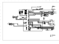
1
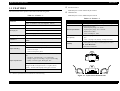
SERVICE MANUAL
Color Inkjet Printer
Stylus C41/42/43/44 series
®
SEIJ01011
Notice
V All rights reserved. No part of this manual may be reproduced, stored in a retrieval system, or transmitted in any form or by any means electronic,
mechanical, photocopying, or otherwise, without the prior written permission of SEIKO EPSON CORPORATION.
V All effort have been made to ensure the accuracy of the contents of this manual. However, should any errors be detected, SEIKO EPSON would
greatly appreciate being informed of them.
V The contents of this manual are subject to change without notice.
V The above not withstanding SEIKO EPSON CORPORATION can assume no responsibility for any errors in this manual or the consequences
thereof.
EPSON is a registered trademark of SEIKO EPSON CORPORATION.
General Notice:Other product names used herein are for identification purpose only and may be trademarks or registered trademarks of their respective owners. EPSON disclaims any and all rights in those marks.
Copyright © 2001 SEIKO EPSON CORPORATION.
Imaging & Information Product Division
PRECAUTIONS
Precautionary notations throughout the text are categorized relative to 1)Personal injury and 2) damage to equipment.
DANGER
Signals a precaution which, if ignored, could result in serious or fatal personal injury. Great caution should be exercised in performing
procedures preceded by DANGER Headings.
WARNING
Signals a precaution which, if ignored, could result in damage to equipment.
The precautionary measures itemized below should always be observed when performing repair/maintenance procedures.
DANGER
1.
ALWAYS DISCONNECT THE PRODUCT FROM THE POWER SOURCE AND PERIPHERAL DEVICES PERFORMING ANY MAINTENANCE OR REPAIR
PROCEDURES.
2.
NO WORK SHOULD BE PERFORMED ON THE UNIT BY PERSONS UNFAMILIAR WITH BASIC SAFETY MEASURES AS DICTATED FOR ALL ELECTRONICS
TECHNICIANS IN THEIR LINE OF WORK.
3.
WHEN PERFORMING TESTING AS DICTATED WITHIN THIS MANUAL, DO NOT CONNECT THE UNIT TO A POWER SOURCE UNTIL INSTRUCTED TO DO SO.
WHEN THE POWER SUPPLY CABLE MUST BE CONNECTED, USE EXTREME CAUTION IN WORKING ON POWER SUPPLY AND OTHER ELECTRONIC
COMPONENTS.
4.
WHEN DISASSEMBLING OR ASSEMBLING A PRODUCT, MAKE SURE TO WEAR GLOVES TO AVOID INJURIER FROM METAL PARTS WITH SHARP EDGES.
WARNING
1.
REPAIRS ON EPSON PRODUCT SHOULD BE PERFORMED ONLY BY AN EPSON CERTIFIED REPAIR TECHNICIAN.
2.
MAKE CERTAIN THAT THE SOURCE VOLTAGES IS THE SAME AS THE RATED VOLTAGE, LISTED ON THE SERIAL NUMBER/RATING PLATE. IF THE EPSON
PRODUCT HAS A PRIMARY AC RATING DIFFERENT FROM AVAILABLE POWER SOURCE, DO NOT CONNECT IT TO THE POWER SOURCE.
3.
ALWAYS VERIFY THAT THE EPSON PRODUCT HAS BEEN DISCONNECTED FROM THE POWER SOURCE BEFORE REMOVING OR REPLACING PRINTED
CIRCUIT BOARDS AND/OR INDIVIDUAL CHIPS.
4.
IN ORDER TO PROTECT SENSITIVE MICROPROCESSORS AND CIRCUITRY, USE STATIC DISCHARGE EQUIPMENT, SUCH AS ANTI-STATIC WRIST STRAPS,
WHEN ACCESSING INTERNAL COMPONENTS.
5.
DO NOT REPLACE IMPERFECTLY FUNCTIONING COMPONENTS WITH COMPONENTS WHICH ARE NOT MANUFACTURED BY EPSON. IF SECOND SOURCE IC
OR OTHER COMPONENTS WHICH HAVE NOT BEEN APPROVED ARE USED, THEY COULD CAUSE DAMAGE TO THE EPSON PRODUCT, OR COULD VOID THE
WARRANTY OFFERED BY EPSON.
TPCS Quality Assurance Department
About This Manual
This manual describes basic functions, theory of electrical and mechanical operations, maintenance and repair procedures of the printer. The instructions and
procedures included herein are intended for the experienced repair technicians, and attention should be given to the precautions on the preceding page.
Manual Configuration
This manual consists of six chapters and Appendix.
CHAPTER 1.PRODUCT DESCRIPTIONS
Provides a general overview and specifications of the
product.
CHAPTER 2.DISASSEMBLY / ASSEMBLY
Describes the step-by-step procedures for disassembling
and assembling the product.
CHAPTER 3.ADJUSTMENT
Provides Epson-approved methods for adjustment.
CHAPTER 4.MAINTENANCE
Provides preventive maintenance procedures and the
lists of Epson-approved lubricants and adhesives
required for servicing the product.
CHAPTER 5.APPENDIX
Provides the following additional information for
reference:
• Electrical circuit boards schematics
• Exploded diagram & Parts List
Symbols Used in this Manual
Various symbols are used throughout this manual either to provide
additional information on a specific topic or to warn of possible danger
present during a procedure or an action. Be aware of all symbols when
they are used, and always read NOTE, CAUTION, or WARNING
messages.
A D J U S T M E N T
R E Q U IR E D
C A U T IO N
C H E C K
P O IN T
W A R N IN G
Indicates an operating or maintenance procedure, practice
or condition that is necessary to keep the product’s quality.
Indicates an operating or maintenance procedure, practice,
or condition that, if not strictly observed, could result in
damage to, or destruction of, equipment.
May indicate an operating or maintenance procedure,
practice or condition that is necessary to accomplish a task
efficiently. It may also provide additional information that is
related to a specific subject, or comment on the results
achieved through a previous action.
I.ndicates an operating or maintenance procedure, practice or
condition that, if not strictly observed, could result in injury or
loss of life.
Indicates that a particular task must be carried out
according to a certain standard after disassembly and
before re-assembly, otherwise the quality of the
components in question may be adversely affected.
Revision Status
Revision
Issued Date
A
March 29. 2002
B
January 20. 2003
Description
First Release
The model name (Stylus C43/C44 series) is added.
CONTENTS
Chapter 1 PRODUCT DESCRIPTION
1.1 FEATURES ......................................................................................................... 9
1.1.1 Model ......................................................................................................... 10
1.1.2 Differences between the Stylus C41/C42 series and the Stylus C40/C20 . 10
1.2 OPERATOR CONTROLS ..............................................................................
1.2.1 Operate Switch ...........................................................................................
1.2.2 Control Panel .............................................................................................
1.2.3 Panel Functions ..........................................................................................
1.2.4 Printer Condition and Panel Status ............................................................
1.2.5 Errors .........................................................................................................
11
11
11
11
11
12
Chapter 2 Disassembly and Assembly
2.1 Overview ............................................................................................................
2.1.1 Precautions .................................................................................................
2.1.2 Tools ..........................................................................................................
2.1.3 Screws ........................................................................................................
2.1.4 Work Completion Check ...........................................................................
14
14
15
16
17
2.2 Disassembly .......................................................................................................
2.2.1 Upper housing removal ..............................................................................
2.2.2 ASF unit removal .......................................................................................
2.2.3 Waste ink pad removal ..............................................................................
2.2.4 PS unit removal ..........................................................................................
2.2.5 Paper eject roller removal ..........................................................................
2.2.6 Paper Guide Upper/Left removal ...............................................................
2.2.7 MAIN board removal ................................................................................
2.2.8 Printhead unit removal ...............................................................................
2.2.9 LD unit removal .........................................................................................
18
18
20
21
22
23
25
27
29
32
Chapter 3 Adjustment
3.1 Overview ............................................................................................................ 34
3.1.1 Required Adjustment .................................................................................
3.1.2 Adjustment Program Initial Setting menu .................................................
3.1.3 Adjustment Program feature ......................................................................
3.1.4 EEPROM initial setting .............................................................................
3.1.5 Head ID ......................................................................................................
3.1.6 Bi-D ...........................................................................................................
3.1.7 USB ID ......................................................................................................
3.1.8 First Dot Position .......................................................................................
3.1.9 Top margin ................................................................................................
3.1.10 Head cleaning ..........................................................................................
3.1.11 Initial ink charge ......................................................................................
3.1.12 Refurbishment for DOA ..........................................................................
3.1.13 Protection counter check .........................................................................
3.1.14 EEPRON check .......................................................................................
3.1.15 EEPROM back up data ............................................................................
3.1.16 A4 pattern will print ................................................................................
34
35
36
38
39
40
42
44
45
46
46
47
48
50
51
52
Chapter 4 Maintenance
4.1 Overview ............................................................................................................
4.1.1 Cleaning .....................................................................................................
4.1.2 Service Maintenance ..................................................................................
4.1.3 Lubrication .................................................................................................
55
55
55
56
Chapter 5 Appendix
5.1 Electrical Circuits ............................................................................................. 59
CHAPTER
PRODUCT DESCRIPTION
Stylus C41/42/43/44 series
Revision B
V Parallel Interface
1.1 FEATURES
EPSON Stylus C41SX .EPSON Stylus C42SX
The main feature of this printer is described in the following table;
V USB Interface
Table 1-1. Feature - 1
Item
EPSON Stylus C41UX .EPSON Stylus C42UX
Description
Table 1-2. Feature - 2
monochrome : 48 nozzles
Item
Printhead
color : 15 nozzles x 3 (Cyan, Magenta, Yellow)
Maximum resolution
Description
Acoustic noize
Level :Approx. 48 dB(A) (According to ISO 7779)
Electrical specification
Universal power supply
• Rated frequency range : 50 - 60 Hz
• Input frequency range : 49.5 - 60.5 Hz
• Rated current : TBD
• Power consumption : TBD
Print capacity
• Black : 300 pages / A4 (ISO/IEC10561 Letter Pattern at 360
dpi)
• Color : 150 pages /A4 (360 dpi, 5% duty each color)
1440 x 720 DPI
Black text :5 PPM
Through put
Black text economy (Memo) : 12 PPM
Text & color graphic : 0.8 PPM
Color printing
4 colors
Interface*1
USB/USB 2.0 or Parallel ( IEEE-1284 compatibility
mode)
Applicable OS
Windows98, Me, XP, 2000, (95), Mac OS
Reliability
Friction feed with ASF : Top in front out
Paper Handling
T Total print volume
: 10,000 pages (A4, Letter) or 20,000 pages (A4, Letter)
T Print Head Life
: 4000 million dots/nozzle
• Holds 100 cut-sheets (65 g/m?)
• Holds 10 envelopes
• Holds 10 transparency films
Cut sheet : A4, Letter, Legal, Half Letter, Exclusive, A5,
A6
Paper Specification
• Thickness : 0.08 mm(0.003") - 0.11 mm(0.004")
• Weight : 64 g/m 2 (17 lb.55Kg) - 90 g/m 2 (24 lb.78Kg)
• Quality : Exclusive paper, Bond paper, PPC
Envelope : No.10, DL, C6, Envelope220*132
Weight :#10,DL,C6 45 g/m 2 (12 lb.) - 75 g/m 2 (20 lb.)
Quality : #10,DL,C6 Bond paper, Plain paper, Air mail
Input buffer
12 KB
“*1” : Interface specification for each model are as the following.
Figure 1-1. Stylus C41/C42 Dimensions
PRODUCT DESCRIPTION
FEATURES
9
Stylus C41/42/43/44 series
Revision B
1.1.1 Model
Table 1-5. Ink cartridge type
Models
The model names are also descriminated by market as followings;
Stylus C41/C42 series
Table 1-3. Model name
Model name
Ink cartridge type
Stylus C40/C20
Market
Stylus C41
Mainly Asia & Pacific market
Stylus C42
Mainly American & European market
Stylus C42Plus
Printer cover : purple
CSIC
No CSIC
USB
The Stylus C4xUX/C2xUX are adopting USB 2.0 interface.
1.1.2 Differences between the Stylus C41/C42 series and
the Stylus C40/C20
The Stylus C41/C42 series are based on Stylus C40/C20, but the some chracteristics
are different from the previous models. The main difference are as followings;
NOTE: The EPSON standard USB cable or less than 3m length USB cable are
commended for connection.
POWER SUPPLY
As, the Stylus C4x are adopting the universal power supply, the power supply board is
only one type.
PRINT SPEED
V Throughput
Table 1-6. Power supply type
Models
Table 1-4. Throughput
Stylus C41/C42
Monochrome text economy
(Memo)
Text monochrome
Stylus C41/C42 series
12 PPM
5 PPM
Stylus C40/C20
8 PPM
4 PPM
Models
series
Stylus C40/C20
Power supply
Universal type
120V AC / 220-240VAC
INK CARTRIDGE
The Stylus Stylus C41/C42 series are adopting the CSIC type ink cartridges, similar to
those of Stylus Photo 870/1270 and lately models.
PRODUCT DESCRIPTION
FEATURES
10
Stylus C41/42/43/44 series
Revision B
1.2 OPERATOR CONTROLS
1.2.4 Printer Condition and Panel Status
Indicators
1.2.1 Operate Switch
Printer status
Operate switch is located on the control panel.
Power ON condition
Powe
Error
Priority
On
-
10
1.2.2 Control Panel
Ink sequence
Blink
-
6
V Switches
Ink Cartridge change mode
Blink
-
5
Data processing
Blink
-
9
Paper Out *1
-
On
4
(1) Power (green)
Lights when the operate switch is "ON", and AC power is supplied.
Paper jam condition*1
-
On 3
3
Ink end(Black)*1
-
On->On
8
(2) Error (red)
Lights or blinks when some error occurs to the printer.
Ink level low(Black)
-
Blink->Blink
8
Ink end(Color)*1
-
On->On
8
1.2.3 Panel Functions
Ink level low(Color)
-
Blink->Blink
8
V Panel Functions
Ink end (Black and Color)
-
On->On
8
No Ink Cartridge (Black or Color)*1
-
On
7
Alt blink
Alt blink
2
Off
On
1
There are 2 non-lock type push switches, and 2 LED.
V Indicators
SW
Error Reset SW
Function
• Loads or Ejects the Paper(Pushing within 3seconds).
• Starts the Cleaning of head(Pushing for 3seconds)
• When carriage is on the Ink Cartridge change position, return
carriage from Ink Cartridge change position.
• Starts the Ink Cartridge change (Pushing for 6seconds)
*This function is not available in printing status.
Error Reset SW
PRODUCT DESCRIPTION
Fatal error*1
“-”:Indicator status don’t change
“a->b”:a is a Indicator condition when carriage is on Home Position.
b is a Indicator condition in Ink exchange sequence.
V Panel Function with Power on
SW
Maintenance request
(Ink Overflow Counter error)
Function
*1 : see “Errors” on page -12.
Starts status printings
OPERATOR CONTROLS
11
Stylus C41/42/43/44 series
Revision B
1.2.5 Errors
V Ink out
When the printer runs out the most part of the ink of any one color, it warns inklow and keeps printing.When the printer runs out the whole ink of any one color, it
stops printing and indicates ink-out error. User is requested to install a new inkcartridge in this state.
V Paper out
When printer fails to load a sheet, it goes paper out error.
V Paper jam
When printer fails to eject a sheet, it goes paper jam error.
V No ink-cartridge
When printer detects that ink-cartridge comes off , it goes this error mode.
V Maintenance request
When the total quantity of ink wasted through the cleanings and flushing is
reaches to the limit, printer indicates this error and stops. The absorber in the
printer enclosure is needed to be replaced with new one by a service person.
V Fatal errors
Carriage control error.
* panel status is described on section1.4.4.
PRODUCT DESCRIPTION
OPERATOR CONTROLS
12
CHAPTER
DISASSEMBLY AND ASSEMBLY
Stylus C41/42/43/44 series
Revision B
2.1 Overview
2.1.1 Precautions
This section describes procedures for disassembling the main components of the Stylus
C41/C42 series. Unless otherwise specified, disassembly units or components can be
reassembled by reversing the disassembly procedure. Things, if not strictly observed,
that could result in injury or loss of life are described under the heading “Warning”.
Precautions for any disassembly or assembly procedures are described under the
heading “CAUTION”. Chips for disassembling procedures are described under the
heading “CHECK POINT”.
If the assembling procedure is different from the reversed procedure of the
disassembling, the procedure is described under the heading “REASSEMBLY”.
Any adjustments required after disassembling the units are described under the heading
“ADJUSTMENT REQUIRED”. When you have to remove any units or parts that are
not described in this chapter, refer to the exploded diagrams in the appendix.
See the precautions given under the handling “WARNING” and “CAUTION” in the
following column when disassembling or assembling the Stylus C41/C42 series
T Disconnect the power cable before disassembling or assembling
W A R N IN G
the printer.
Read precautions described in the next section before starting.
T If you need to work on the printer with power applied,
strictly follow the instructions in this manual.
T Wear protective goggles to protect your eyes from ink. If ink gets
T
T
T
T
T
Disassembly and Assembly
Overview
in your eye, flush the eye with fresh water and see a doctor
immediately.
Always wear gloves for disassembly and reassembly to avoid
injury from sharp metal edges.
To protect sensitive microprocessors and circuitry, use static
discharge equipment, such as anti-static wrist straps, when
accessing internal components.
Never touch the ink or wasted ink with bare hands. If ink comes
into contact with your skin, wash it off with soap and water
immediately. If irritation occurs, contact a physician.
When a lithium battery is installed on the main board of this
printer, make sure to observe the following instructions when
serving the battery:
1.Keep the battery away from any metal or other batteries so that
electrodes of the opposite polarity do not come in contact with each
other.
2.Do not heat the battery or put it near fire.
3.Do not solder on any part of the battery. (Doing so may result in
leakage of electrolyte from the battery, burning or explosion. The
leakage may affect other devices close to the battery.)
4.Do not charge the battery. (An explosion may be generated inside the
battery, and cause burning or explosion.)
5.Do not dismantle the battery. (The gas inside the battery may hurt your
throat. Leakage, burning or explosion may also be resulted.)
6.Do not install the battery in the wrong direction. (This may cause
burning or explosion.)
Danger of explosion if the battery is incorrectly replaced.
Replace only with the same or equivalent type recommended by
the manufacture. Dispose the used batteries according to
government’s law and regulations.
14
Stylus C41/42/43/44 series
W A R N IN G
T
T
T
T
T
C A U T IO N
C A U T IO N
Revision B
2.1.2 Tools
Avant de commencer, assurez vous que l’imprimante soit eteinte
et que le cordon d’alimentation soit debranche.
Lorsque vous changez la pile au lithium, assurez vous que la
nouvelle respecte bien les caracteristiques requises.
Lorque que vous installez la pile au lithium, faites attention a
l’inserer dans le bon sens en respectant la polarite.
Veillez a jeter les piles usagees selon le reglement local.
Ne rechargez pas les piles au lithium.
Use only specified tools to avoid damaging the printer.
Risque d’explosion si la pile est remplacée incorrectment. Ne
remplacer que par une pile du même type ou d’un type équivalent
recommandé par le fabricant. Eliminer les piles déchargées selon les
lois et les règles de sécurité en vigueur.
Table 2-1.
Name
Supplier
Parts No.
Phillips Screw Driver (No.1)
EPSON
B743800100
Phillips Screw Driver (No.2)
EPSON
B743800200
Nipper
EPSON
B740500100
Tweezers
EPSON
B741000100
T Never remove the ink cartridge from the carriage unless this
T
T
T
T
T
manual specifies to do so.
When transporting the printer to the customer after servicing, be
sure to pack the printer for transportation without removing the
ink cartridge.
Use only recommended tools for disassembling, assembling or
adjusting the printer.
Observe the specified torque when tightening screws.
Apply lubricants and adhesives as specified. (See “Maintenance”
on page 54 for details.)
Make the specified adjustments when you disassemble the
printer.
(See “Adjustment” on page 33 for details.)
7.
Disassembly and Assembly
Overview
15
Stylus C41/42/43/44 series
Revision B
2.1.3 Screws
Table 2-2.
No.
Name and Specification
1
CBS 3x6
2
CBP 3x8
3
CBS (P2) 3x6
4
CBS 3x8
5
C.P.F.S-Tite 3x12
Disassembly and Assembly
Outward Form
Overview
16
Stylus C41/42/43/44 series
Revision B
2.1.4 Work Completion Check
Table 2-3. Work Completion Check (continued)
Classification
If any service is made to the printer, use the checklist shown below to confirm all works are
completed properly and the printer is ready to be returned to the user.
Table 2-3. Work Completion Check
Classification
Lubrication
Item
Self-test
On-line Test
Printhead
Carriage
Mechanism
Main Unit
Check Point
Status
V
Is the operation normal?
V
V
Is the printing successful?
V
Is ink discharged normally from V
all the nozzles?
V
V
Does it move smoothly?
V
V
Is there any abnormal noise
during its operation?
V
V
Is there any dirt or foreign
objects on the CR Guide Shaft? V
V
Is the CR Motor at the correct
temperature?
V
(Not too heated?)
Paper Feeding
Mechanism
Is paper advanced smoothly?
• No paper jamming?
• No paper skew?
• No multiple feeding?
• No abnormal noise?
Is the PF Motor at correct
temperature?
Is the paper path free of any
obstructions?
Adjustment
Specified
Adjustment
Disassembly and Assembly
Are all the adjustment done
correctly?
Item
Specified
Lubrication
Checked
Not necessary
Checked
Others
Checked
Is the amount of lubrication
correct?
Are the ink cartridges installed
correctly?
Protective
Materials
Have all relevant protective
materials been attached to the
printer?
Attachments,
Accessories
Have all the relevant items been
included in the package?
Checked
Not necessary
Are all the lubrication made at
the specified points?
Ink Cartridge
Packing
Not necessary
Check Point
Status
V
V
V
V
V
V
V
V
Checked
Not necessary
Checked
Not necessary
Checked
Not necessary
Checked
Not necessary
V Checked
V Not necessary
Not necessary
Checked
Not necessary
Checked
Not necessary
Checked
Not necessary
V Checked
V Not necessary
V
V
V
V
V
V
Checked
Not necessary
Checked
Not necessary
Checked
Not necessary
Overview
17
Stylus C41/42/43/44 series
Revision B
2.2 Disassembly
2.2.1 Upper housing removal
The flowchart below shows step-by-step disassembly procedures. When disassembling
each unit, refer to the page number shown in the figure.
1.
Upper housing
removal
Page 18
Move the edge guide to the right until it stops moving. Make sure the edge guide is
in the upper housing’s notch position.
Edge guide
ASF unit
removal
Printhead unit
removal
Paper eject
roller removal
Page 20
Page 29
Page 23
PS unit
removal
Page 22
MAIN board
removal
LD unit
removal
Page 27
Page 32
Waste ink pad
removal
Page 32
Figure 2-2. Position of Edge guide
Figure 2-1. Disassembling Flowchart
C A U T IO N
Do not remove the Main Frame from the Lower Housing to avoid the
deformation of the Main Frame.
Therefore, you cannot remove the following parts.
T Lower Housing
T Main Frame
T PF Motor
T Pump Unit
T Cap Unit
T PF Roller Assy.
Disassembly and Assembly
Disassembly
18
Stylus C41/42/43/44 series
2.
Revision B
Remove the 2 hooks at the front using a precision screwdriver (-).
C A U T IO N
3.
Remove the 2 hooks on the sides by pushing the tops of the hooks up.
The printer should not turn when the front 2 hooks are removed.
Upper housing
Figure 2-4. Removing the side hook
4.
Remove the 3 hooks at the back using a (-) screwdriver or similar tool.
Figure 2-3. Removing the front hook
Figure 2-5. Removing the back hook
Disassembly and Assembly
Disassembly
19
Stylus C41/42/43/44 series
Revision B
2.2.2 ASF unit removal
1.
Remove the upper housing. (Refer to Section 2.2.1)
2.
Take out the three screws.
CBP 3×8
3
1
A D J U S T M E N T
R E Q U IR E D
The Top Margin adjustment is required when the ASF unit is
replaced.
CBS (P2) 3×6
2
CBP 3×6
Figure 2-6. Removing the ASF unit
3.
Pull the ASF unit toward the rear and remove it.
T When installing the ASF unit, install the spring in the guide, then
install it while supporting it by hand.
Figure 2-7. reassembling the ASF unit
T When reassembling the ASF unit tighten screws form lower
numbers in Figure2-6.
T Tightening Torque for screw
- C.B.S 3x6
- C.B.S (P2) 3x6
- C.B.P 3x8
Disassembly and Assembly
: 9+/-1 kgf.cm
: 9+/-1 kgf.cm
: 6+/-1 kgf.cm
Disassembly
20
Stylus C41/42/43/44 series
Revision B
2.2.3 Waste ink pad removal
1.
Remove the upper housing. (Refer to Section 2.2.1)
2.
Remove the ASF unit. (Refer to Section 2.2.2)
3.
Remove the Waste ink pad.
tube stopper
A D J U S T M E N T
R E Q U IR E D
When the Waste ink pad is replaced with a new one, following service
item is required.
T Waste ink counter reset operation. ( Section 3.1.13 on page 48.)
Waste ink pad
Figure 2-8. Removing the Waste ink pad
T When assembling the Waste ink pad, be sure to set the tip of the
ink tube in the correct position of the Waste ink pad. Otherwise
it will cause ink leakage.
Figure 2-9. Tip of ink tube setting position
Disassembly and Assembly
Disassembly
21
Stylus C41/42/43/44 series
Revision B
2.2.4 PS unit removal
T When installing the PS unit, make sure the claws are attached to
the hooks on the lower housing.
1.
Remove the upper housing. (Refer to Section 2.2.1)
2.
Remove the ASF unit. (Refer to Section 2.2.2)
3.
Disconnect the cable from the connector (CN2) on the main board using tweezers,
etc.
4.
Take out the 2 screws.
CN2
PS unit
Figure 2-11. Reassembling the PS unit
C.B.S 3×6
T Do not insert the pin of the PS cable to the leftmost side of the
connector because the 1st pint of its cable is cut.
C.B.P 3×8
Figure 2-10. Removing the PS unit
5.
Pull the PS unit out while lifting up on it.
Blue line
marking
Figure 2-12. Connecting the PS cable(CN2)
T Tightening Torque for screw
- C.B.S 3x6
- C.B.P 3x8
Disassembly and Assembly
Disassembly
: 6+/-1 kgf.cm
: 6+/-1 kgf.cm
22
Stylus C41/42/43/44 series
Revision B
4.
2.2.5 Paper eject roller removal
1.
Remove the upper housing. (Refer to Section 2.2.1)
2.
Grip the dowel pin of the PE roller’s gear, turn it clockwise and release the
carriage lock.
Protrusion
Take out the two screws.
CBS 3×6
Figure 2-14. Take out the screw
5.
Return the carriage to the home position, then remove the Front Frame.
Figure 2-13. Releasing the carriage lock
3.
Move the carriage to the center.
Front Frame
Figure 2-15. Removing the Front Frame
Disassembly and Assembly
Disassembly
23
Stylus C41/42/43/44 series
6.
Revision B
Slide the PE roller to the left side, then remove the claw extending from the lower
housing.
C A U T IO N
Paper Eject roller
T If the Paper eject roller gear and Paper eject roller shaft are
removed or , make sure that neither of the Paper eject roller
shaft hooks is damaged.
If either of the hooks is damaged, it should be replaced with a
new one.
hook
Figure 2-16. Releasing the claw extending
7.
Remove the gear from the frame, then remove the Paper eject roller.
Figure 2-18. Hook of Paper eject roller
T Tightening Torque for screw
- C.B.S 3x6 screw for Front frame
: 6+/-1 kgf.cm
Gear
Figure 2-17. Removing the Paper eject roller
Disassembly and Assembly
Disassembly
24
Stylus C41/42/43/44 series
Revision B
3.
2.2.6 Paper Guide Upper/Left removal
C A U T IO N
Press the dowel of the paper guide unit with tweezers, etc., then pull it forward and
remove it.
Perform this operation by the following procedures so that the coating
material of the PF roller does not damage.
1.
Remove the upper housing. (Refer to Section 2.2.1)
2.
Place the OHP sheet between the Paper Guide Upper/Left and the PF roller by
rotating the protrusion of the Paper Eject roller gear in CW direction.
OHP paper
dowel
Figure 2-20. Removing the Paper Guide Upper/Left
Protrusion
Figure 2-19. Place the OHP sheet
Disassembly and Assembly
Disassembly
25
Stylus C41/42/43/44 series
1.
Revision B
Insert the tip of the spring to the Paper Guide.
3.
Figure 2-21. Setting the spring to the Paper Guide
2.
Assemble the Paper Guide Upper/Left to the Main Frame.
Figure 2-23. Assembling the Paper Guide 1
Place the OHP sheet on the PF roller.
4.
Fix the dowel of the Paper Guide Upper/Left to the hole of the Main
Frame by sliding the Paper Guide Upper/Left to the right side. And,
release the spring from the hook of the Paper Guide Upper/Left.
dowel
OHP paper
Release the spring
Figure 2-22. Placing the OHP sheet
Figure 2-24. Assembling the Paper Guide 2
Disassembly and Assembly
Disassembly
26
Stylus C41/42/43/44 series
5.
Revision B
Eject the OHP sheet from the printer by rotating the protrusion of
the Paper Eject roller gear in CW direction.
2.2.7 MAIN board removal
1.
Remove the upper housing. (Refer to Section 2.2.1)
2.
Remove the ASF unit. (Refer to Section 2.2.2)
3.
Remove the PS unit. (Refer to Section 2.2.4)
4.
Remove the three screws, then remove the shield cover.
Protrusion
Figure 2-25. Ejecting the OHP sheet
Disassembly and Assembly
Disassembly
27
Stylus C41/42/43/44 series
Revision B
5.
Disconnect the four connectors (CN9, CN4, CN7, CN12).
USB Type
CBS 3×6
CBS 3×8
CN9
CN4
CN7
CN12
Figure 2-27. Disconnecting the connectors
Parallel Type
6.
Take out the 1 screw. (Refer to Figure 2-27.)
7.
Lift the MAIN board up and remove it.
C.P.F.S-Tight 3×12
Tightening Torque for screw
T USB Type
- C.B.S 3x6 screw
- C.B.S 3x8 screw
T Parallel Type
- C.B.S 3x6 screw
- C.P.F.S-Tight 3x12 screw
- C.B.S 3x8 screw
CBS 3×6
: 9+/-1 kgf.cm
: 9+/-1 kgf.cm
: 9+/-1 kgf.cm
: 9+/-1 kgf.cm
: 9+/-1 kgf.cm
Figure 2-26. Removing the Shield cover
Disassembly and Assembly
Disassembly
28
Stylus C41/42/43/44 series
Revision B
2.2.8 Printhead unit removal
A D J U S T M E N T
R E Q U IR E D
When replacing the Main board with a new one, perform the
following service items.
T Before removing the Main Board, connect the parallel cable or
USB cable and try to read out the following data by using the
Adjustment program. If this operation succeeds, replace the
Main board and write the read out data to the new Main
board through the Adjustment program. (“EEPROM back up
data” on page 51)
1) I/C Ink consumption counter.
2) Waste ink drain pad counter.
3) EEPROM Initial setting
4) Head ID input
5) Top margin adjustment
6) Bi-D adjustment
In case the above mentioned data are not able to be read out from the
defective Main board, perform the following service items.
T Replace the both ink cartridges with a brand new one.
T Replace the Waste ink pad with a new one.
T Reset the Ink pad counter
T Input the EEPROM initial setting value
T Input the Head ID
T Adjust the Top margin
T Adjust the Bi-D alignment.
1.
Remove the upper housing. (Refer to Section 2.2.1)
2.
Remove the ink cartridges.
3.
Move the carriage to the center.
4.
Take out the screw, then remove the CR motor from the frame.
CR motor
CR pinion gear
CBS 3×6
Figure 2-28. Removing the CR motor
5.
Remove the timing belt from the Carriage pinion gear.
C A U T IO N
T Do not remove the below screw, fixing the driven pulley.
Because, the screw has been fixed in the static temparature
condition. If removed, the Bi-D will be changed in
widetemparature range.
Screw
Disassembly and Assembly
Disassembly
29
Stylus C41/42/43/44 series
Revision B
FFC
T When reassembling the CR motor, it contact the lib of Main
frame after turning clockwise.
Carriage unit
CSIC board
connector
lib
Figure 2-30. Disconnecting the FFC
7.
Release the two hook, fixing between the Printhead unit and carriage cover, on the
both sides of the carriage unit, then pull the unit forward and remove the cover.
Figure 2-29. Reassembling the CR motor
T Tightening Torque for screw
- C.B.S 3x6 screw
6.
: 9+/-1 kgf.cm
Release the FFC form the fixing points of the carriage and disconnect the FFC
from the CSIC board connector on the carriage unit.
Figure 2-31. Release the two hooks
8.
Disassembly and Assembly
Disassembly
Lift the Printhead unit up and remove it.
30
Stylus C41/42/43/44 series
Revision B
T If the Carriage unit is disassembled or replaced with a new one,
make sure that the Carriage timing belt is set in the assembling
groove correctly as following figure.
Timing belt
Printhead unit
Figure 2-32. Removing the Printhead unit
9.
Disconnect the FFC from the connector.
A D J U S T M E N T
R E Q U IR E D
FFC
When the Printhead is replaced with a new one, following adjustments
must be performed in the order below: Refer to Table 3-1.
1. Initial ink charge
2. Head ID input
3. Bi-D adjustment
When the Printhead is removed and reinstalled, only the following
adjustment is required. Refer to Table 3-1.
1. Head cleaning
2. Bi-D adjustment
Figure 2-33. Disconnecting the FFC
Disassembly and Assembly
Disassembly
31
Stylus C41/42/43/44 series
Revision B
2.2.9 LD unit removal
T When reassembling the LD unit, make sure that seven hooks are
1.
Remove the upper housing. (Refer to Section 2.2.1)
2.
Remove the ASF unit. (Refer to Section 2.2.2)
3.
Disconnect the cables which are connected to the LD unit.
4.
Disconnect connector CN4 form the MAIN board.
set to the Main frame.
LD unit
Figure 2-36. Setting seven hooks
Cables
A D J U S T M E N T
R E Q U IR E D
Figure 2-34. Disconnecting the Cables
5.
The Top Margin adjustment is required when the LD unit is replaced.
Push the two hooks on the LD unit, then lift it up and remove hook of pump unit
Hooks
Figure 2-35. Removing the LD unit
Disassembly and Assembly
Disassembly
32
CHAPTER
ADJUSTMENT
Stylus C41/42/43/44 series
Revision B
3.1 Overview
This section describes the procedure for adjustments required when the printer is
disassembled and assembled for repair or service.
3.1.1 Required Adjustment
Table 5-1 lists all the necessary adjustments for this printer. If any service listed in this
table is carried out, all adjustments corresponding to that service item should be
performed to ensure proper operation of the printer.
Table 3-1. Required Adjustment
Performance
Priority
1
2
Replacing parts/
Service item
EEPROM
initial
setting
Ink pad
Counter
reset
Initial Head
USB
Top margin Bi-D
Ink
ID
ID
Adjustment Adjustment
Charge Setting
Input
Replacing the
Main Board
?
@
NA
A
B
C
D
Removing the
Printhead unit
NA
NA
NA
NA
NA
Å
NA
Replacing the
Printhead unit
NA
?
@
A
NA
B
NA
Replacing the
Printer mechanism
NA
NA
?
@
A
B
NA
Replacing the
Waste drain ink
pad
NA
?
NA
NA
NA
NA
NA
Removing or
Replacing the ASF
unit
NA
NA
NA
NA
?
NA
NA
Removing or
Replacing the LD
unit
NA
NA
NA
NA
?
NA
NA
Adjustment
3
4
5
6
7
NOTE: • “O”: Required Adjustment. The number in the circle shows the required
adjustment order.
“NA”: Not applicable.
• Following adjustments are not required on this product.
-Platen Gap adjustment
-Head Angular adjustment.
• When the Main board is replaced with new one, you may have to
replace the following parts also in case the EEPROM parameter back up
function is not available on the defective main board.
* Waste drain ink pad
* Both Black & Color Ink Cartridge
This section describes the detailed procedures of each adjustment by Adjustment
Program.
In this printer, it is necessary to set the adjusting information for each printer
mechanism in order to maintain consistent printing function and quality, eliminating
differences of each printer mechanism’s characteristics. Therefore, in case that the
combination of the printer mechanism and main board changes or the print head is
replaced during the repair service, you must set and save the correct information to the
MAIN board, using the exclusive adjustment program.
Overview
C H E C K
P O IN T
In case any parts is removed and assembled on the repair product
while running the Adjustment program, turn off the printer
certainly.
34
Stylus C41/42/43/44 series
Revision B
2.
3.1.2 Adjustment Program Initial Setting menu
Select the Interface port number which you connect the printer to your PC.
You have to input the following four items before entering the adjustment main menu.
V Model name (Stylus C41UX/41SX/42UX/42SX)
For the Stylus C41UX, select Model name “Stylus C41UX.”
V Interface setting (LPT1, LPT2, LPT3, EPUSB1, EPUSB2, EPUSB3)
1.
When you run this program, the following menu appears. Select the model name
in the screen below.
Figure 3-2. Interface Setting
Figure 3-1. Model Name Selection
NOTE: This printer stores model name in the PROM. Therefore, even you select
the model name in the screen above, model name will not stored in the
EEPROM. Selecting model name in the screen above determines
respective special command for each model.
Adjustment
Overview
35
Stylus C41/42/43/44 series
Revision B
The user interface of the main menu on this program is shown below.
3.1.3 Adjustment Program feature
The adjustment program enables you to set various values correctly to prevent
malfunction and fluctuation of printing quality and printing function caused by
difference in components and assembly when the printer components are replaced
during repair. Basic adjustment items by using this program are shown as fellows.
C H E C K
P O IN T
T This program does not operate under DOS or Windows 3.X, NT,
but operates Windws95/98 only.
T Perform this adjustment program using parallel I/ F or USB.
Table 3-2. Basic adjustment items
No
Main Menu
Service
Figure 3-3. Adjustment program main menu
EEPROM initial setting
Head ID input
Bi- D adjustment
1
Adjustment
Top margin
Additionally, this program runs under the D4 (IEEE-1284.4) protocol. So, this program
can get the several error statuses even if the printer is error condition, and can control
the printer under the error condition. Following explain you the common function of
the Adjustment program.
Head cleaning
V Quit
Initial ink charge
If you want to exit this program, click the “Quit” button. Following menu is displayed
on the screen. And clicking the “Quit” Button in the following menu exit the
adjustment program completely. Clicking the “Next” button returns to the Top menu
(Initial setting menu) of Figure 5-3.
USB ID input
First dot position
Refurbishment for DOA
2
The “Adjusted item” in the right column shows you the adjusted item which executed
in this program and it is easy to confirm the adjusted value.
Maintenance
Protection counter check
EEPROM check
EEPROM back up data
3
Print A4 pattern
A4 pattern will print
Figure 3-4. Quit function
Adjustment
Overview
36
Stylus C41/42/43/44 series
Revision B
V Get status
This function is used to get the printer status and following figure is displayed on the
screen by clicking the “Get status” button. This function can get the printer status even
if the printer is error condition except the main logic circuit failure, and control the
printer by using the D4 mode functions.
C A U T IO N
This program dose not display the “Paper out” error status in the
Bi-d adjustment even if the paper is out in the ASF. When the
paper is out in the ASF, this program continues to send the paper
feed command until the paper is set in the ASF.
Figure 3-5. Get status function
Adjustment
Overview
37
Stylus C41/42/43/44 series
Revision B
3.1.4 EEPROM initial setting
This function is used when replacing the MAIN board.
Using this function enables writing of the initial setting values to the new MAIN
board’s EEPROM.
1.
Choose the “EEPROM initial setting” in the Adjustment menu.
Figure 3-7. EEPROM initial setting (2)
Figure 3-6. EEPROM initial setting (1)
2.
Click the “OK” button, then the initial setting values are written to the MAIN
board. If choose “Check“, the destination setting will be appera.
Adjustment
Overview
38
Stylus C41/42/43/44 series
Revision B
4.
3.1.5 Head ID
This adjustment function is required when any of the following parts is replaced.
Choose the “Check present data” and click the OK button. Following Check
present data menu is displayed. Click the OK button, then readout data is
displayed.
V Printhead
V Main board
V Printer mechanism
This adjustment function enables you to write printhead Voltage ID into the specific
address of the EEPROM. This operation is considered the most important to maintain
proper ink discharging system. If any ID is not written correctly, it results in white or
color lines and also gives bad influence on dot weight.
1.
When replacing any of the parts above, make a note of VH voltage ID in advance.
You can find the VH voltage ID on the following position:
T Printhead: On the top right face of the printhead.
A 6-digit ID code is printed with the QR code on the label.
Figure 3-9. Read out the Head ID from the EEPROM
T Printer mechanism: On the label of the packing box of the printer mechanism.
2.
Run the Adjustment program and enter the Adjustment Main menu.
3.
Choose the “Head ID” and click it. The menu shown in the next page appears.
Choose the “Change data” item in the Head ID input menu and click the OK
button. Following Head ID input menu is displayed. Input a 6-digit code of the
Head Voltage ID in the following menu.
Figure 3-8. Head ID input menu
Figure 3-10. Entering the 6-digits Head ID
Adjustment
5.
Overview
39
Stylus C41/42/43/44 series
6.
Revision B
When the Head ID is input and writes to the EEPROM, the message is displayed
on the bottom column in the menu.
3.1.6 Bi-D
You perform this adjustment to correct differences in printing positions, which is
caused by incorrect of printing timing in right and left directions during the Bidirectional printing. Therefore, you are required to perform this adjustment after
performing the following operations.
T Replacing the Print mechanism
T Replacing the main board
T Replacing the CR motor
T Replacing the Printhead
1.
Choose the “Bi-D” in the “Adjustment menu” as following figure.
Figure 3-11. Choose the Bi-d adjustment
Adjustment
2.
Choose the “Print the Bi-d adjustment pattern” in the “Bi-Directional Adjustment
pattern” and click the “OK” button.
Overview
40
Stylus C41/42/43/44 series
Revision B
Figure 3-12. Bi-d adjustment pattern
Figure 3-13. Choose the misaligned dot size
NOTE: As shown in the sample, gaps between passes are sometimes created in
different directions among patterns. This unexpected change in direction
is caused by an ink jet printer-specific reason, which is an ink jet printer
inevitably performs a periodical cleaning specified by the flashing timer
even during Bi-D pattern printing, so that the printing direction suddenly
changes. However, this directional difference among Bi-D patterns
should not be considered, and you can always confirm and adjust the
pattern correctly by referring to gap amount only.
5.
3.
Click the “Previous” and go back to the “BI-Directional Adjustment” menu. And
choose the “Adjust” menu and click the “OK” button.
4.
Check the printed pattern and find the misaligned dot type. Choose the
misaligned dot size in the following menu and click the “OK” button.
By choosing the misaligned dot size, following input menu for the adjustment
value is displayed. Check the printed pattern again and Input the suitable value in
the following menu and click the “OK” button.
Figure 3-14. Bi-d adjustment input menu
Adjustment
6.
The following menu appears. Press “OK“ to system reset to the printer. The input
value is written in the specific address of the EEPROM.
Overview
41
Stylus C41/42/43/44 series
Revision B
3.1.7 USB ID
When you replace the main board with a new one, you have to input the USB ID newly
into the specific address of the EEPROM. When the Printer and the PC are connected
with a USB cable, the USB port driver loads the unique code from the specific address
of the printer’s EEPROM and the provides the USB port number to the unique code.
The USB port driver controls the several USB ports under the Windows 98
environment.
Figure 3-15. System reset of the printer
7.
To confirm if the adjustment value is suitable, click the “Previous” button and go
back to the “Bi-Directional Adjustment” menu. Choose the “Print the Bi-D
adjustment patter” and click the “OK” button.
8.
Repeat from Step1 to the previous step to align the Bi-D pattern.
A unique code called USB ID is input to the specific address of the EEPROM in our
manufactory and the following total 18-digit code is used as a USB ID for the EPSON
ink jet printer.
T Factory line number (3-digit)
T PC number (2-digit)
T Input year/month/date/time (hour, minutes, second) (12-digit)
The timer data of the PC is used for this input data.
T Number 0
A “0” is automatically added for the last digit in the input program.
In repair activity, we use a 10-digit code of the Serial number for a USB ID. The
remaining 8digits code is generated in the adjustment program and added to the serial
number automatically.
Adjustment
Overview
42
Stylus C41/42/43/44 series
C A U T IO N
1.
Revision B
T In case the USB ID is not input in the adjustment program after
2.
Choose the “Input USB ID” and click “OK” button in the “USB ID check/Input”
menu. Following menu is displayed.
the main board is replaced to new one, the USB ID may not
possibly unique one. In this case, the USB ID conflicts another
peripheral USB ID in the USB port driver and the another USB
peripheral may not possibly be used with the USB.
T This menu is only appeared in case of connecting to USB model.
Choose the “USB ID input” in the Adjustment menu.
Figure 3-17. Choose the USB ID input menu
3.
Figure 3-16. Choose the USB ID input menu
Adjustment
Check the 10digits code of the serial number on the serial number label stuck
around the rear side of the Upper housing. Input the 10digits code of the serial
number in the input menu and click “OK” button.
NOTE: Even though you input irresponsible another 10digits code and click the
“OK” button, the program allow to input the code and write down it the
specific address of the EEPROM. But, there is a possibility that the code
is not unique and the code conflicts another USB ID in the USB port
driver.
Overview
43
Stylus C41/42/43/44 series
Revision B
3.1.8 First Dot Position
This Adjustment revises gap of left margin ( Print start position) of post card printing
and A4 printing.
5.
Press [OK] button after confirming.
6.
Repeat above 2 to 5 and adjust so that left margin will be 3+/-1.5mm.
T While warming up (Power LED blinking condition),Program
can not be executed (communication error happens). Execute
program on condition that Printer power LED is turning on.
T Whenever input step 1, it changes by 1/2880dpi (0.009mm).
Figure 3-18. First Dot Position Adjustment
The figure indicated in the center of Adjustment window is the current figure recorded
in EEPROM.
1.
Press [Print] button and print Adjustment Pattern.
Figure 3-19. First Dot Position Pattern
2.
Measure the distance (left margin) from the paper left edge of print pattern to vertical
pole of print start position.( Refer to Figure 3-36)
3.
Change setting by pressing “r” “s” button beside or under the predetermined figure.
4.
If following indication appears, set printer power OFF/ON in order to record
predetermined limit to printer at first.
Adjustment
Overview
44
Stylus C41/42/43/44 series
Revision B
2.
3.1.9 Top margin
Choose the “Print the Top margin” in the “Top margin adjustment” and click the
“OK” button.
This function can be used to change the top margin value.
You are required to perform this adjustment after performing the following operations.
T Removing or replacing the ASF unit.
T Removing or replacing the LD unit.
T Replacing the Printer mechanism
Figure 3-21. Top margin adjustment pattern
T Replacing the main board
1.
Choose the “Top margin” in the Adjustment menu.
3.
Check that the printed horizontal line is in 2.6mm ~ 7.2mm from the top of the
paper. If it is out of the specific range, perform the Top Margin adjustment by the
following procedure.
4.
When adjusting the top margin, select “Adjust” from “Top margin adjustment”,
the click the “OK” button.
Figure 3-20. Choose the Top margin menu
Adjustment
Overview
45
Stylus C41/42/43/44 series
Revision B
3.1.10 Head cleaning
3.1.11 Initial ink charge
This printhead cleaning is CL1’ and about 1/8 of the brand-new black I/C and 1/17 of
the brand-new color I/C are consumed. Before use this function, check the remaining
ink amount of the both I/C by using the “Get status” function.
After you replaced any of the following units, perform initial ink charge and return the
printer after making sure that ink is ejected correctly from the printhead.
1.
T After replacing the printer mechanism
Choose the “Head cleaning” in the Maintenance menu.
T After replacing or removing the printhead
C A U T IO N
1.
Before you perform the initial ink charge operation, replace the
installed cartridges with new ones, because the ink amount used
for the initial ink charge operation is so large.
Choose the “Initial ink charge” in the Maintenance menu.
Figure 3-22. Choose the Head cleaning menu
2.
Click the “OK” button in the menu. The powerful cleaning is performed.
Figure 3-23. Choose the Initial Ink Charge menu
2.
Click the “OK” button in the menu. The initial ink charge is performed.
NOTE: As described in the menu message, about 1/4 amount of the Black ink
cartridge and 1/9 amount of the Color ink cartridge are consumed in the
initial ink charge operation.
Adjustment
Overview
46
Stylus C41/42/43/44 series
Revision B
3.1.12 Refurbishment for DOA
If you clean the cavity of the printhead and cap assembly, this function will be useful.
C A U T IO N
Set the dummy cartridge in the printer using the ink replacement function.
3.
Select “Yes” under “Item,” then click the “OK” button. The “Refurbishment for
DOA” function is then executed.
T After carry out this function, replace the waste drain ink pad
T
T
T
T
T
1.
2.
with new one and reset the Waste drain ink pad counter.
Otherwise, the ink or S46 liquid may leak from the pad during
the transportation.
Prepare the following tool.
*Dummy ink cartridge, Injector, S46 liquid
Do not carry out this program repeatedly. This operation is
available only one time. Excessive operation causes overflow of
the ink and S46 liquid.
When you refurbish the repair product by using this program,
do it on your responsibility.
When you charge S46 liquid into the dummy ink cartridge with
the Injector, make sure fill out the dummy ink cartridge with S46
liquid. In case enough S46 liquid is not charged into the dummy
cartridge, the printhead will not cleaned and not filled with the
S46 liquid enough in this operation.
Keep the S46 liquid and the dummy ink cartridge clean.
Choose the “Refurbishment for DOA” in the Maintenance menu.
Figure 3-24. Choose the Refurbishment for DOA menu
Adjustment
Overview
47
Stylus C41/42/43/44 series
Revision B
2.
3.1.13 Protection counter check
The program allows you to check or clear the current protection counter value (waste
ink amount counter).
After read the Caution description on the above menu, click the “OK” button in the
menu. The present counter value is displayed on the bottom column as following
figure.
Check the present counter value
1.
Choose the “Check the present counter values” in the “Maintenance” menu and
click the “OK” button.
Figure 3-26. Present counter value
3.
If the present counter value is over 5845 points, we recommend you to replace the
Waste ink drain pad to new one.
Overview
48
Figure 3-25. Choose the Check the present counter value
Adjustment
Stylus C41/42/43/44 series
Revision B
Clear the present counter value
1.
Choose the “Clearning the present counter values” in the “Ptotection counter
maintenance” menu and click the “OK” button.
C A U T IO N
Be sure to replace the installed waste ink pad with a new one after
or before you clear the current protection counter value.
C H E C K
P O IN T
The initial value of the Protection counter is differ by destination
as bellow:
T ESP :
0
T Excepting ESP:
2940
Figure 3-27. Choose the Clear the present counter value
2. After you read the description on the menu, click the “OK” button.
Figure 3-28. Clear the present counter value
Adjustment
Overview
49
Stylus C41/42/43/44 series
Revision B
3.1.14 EEPRON check
You can check the EEPROM data or can write the specific data into the specific
address of the EEPROM directly even if the printer is error condition. (In case one of
the main logic circuit such as CPU, I/F receiver IC, RAM, EEPROM is broken, this
function is not available) Select the “EEPROM check” function in the Maintenance
menu.
The main menu of this function is as following figure. The following two functions are
built in this program.
Figure 3-30. Check the EEPROM data
T Change EEPROM data
You can change the specific data stored in the specific address of the
EEPROM.
However, do not use this function except the special case. Careless usage
causes any trouble.
Figure 3-29. EEPROM check function
T Check the EEPROM data
You can check the specific data stored in the specific address of the
EEPROM.
Input the specific address with hexadecimal code. Use this function in your
analysis usefully.
Figure 3-31. Change the EEPROM data
Adjustment
Overview
50
Stylus C41/42/43/44 series
Revision B
3.1.15 EEPROM back up data
This function is used when replacing the MAIN board.
Using this function, the data on the currently used MAIN board are backed up, then the
backed up data can be written to the EEPROM on the new MAIN board after
replacement.
Figure 3-33. Replace the defective main board with new one
C H E C K
P O IN T
1.
This function may fail. If it fails, replace the MAIN board with a
new one, then carry out the specified adjustments in order.
3.
The backed up data will be written to the EEPROM on the new MAIN board.
Choose the “EEPROM backup data” in the Maintenance menu.
Figure 3-32. EEPROM backup data
2.
The EEPROM data on the current MAIN board are backed up by clicking the
“OK” button. The following message is displayed when the data backup operation
is completed. Replace the printer’s MAIN board, then turn the power ON again
and click the “OK” button.
Adjustment
Overview
51
Stylus C41/42/43/44 series
Revision B
3.1.16 A4 pattern will print
We recommend to use this function to check the repaired product quality in your final
stage of your repair. The following 6 items are printed on the check pattern.
C H E C K
P O IN T
T The check point for the first black and each color solid pattern
(beta pattern 360 x 360dpi normal dot) in the A4 Check pattern
is as follows.
-Any white line is not observed.
-Uneven banding is not observed extremely.
T The check point for the second Nozzle check pattern (120dpi) is
as follows.
-Ink is fired from all nozzles.
-Uneven banding is not observed extremely.
T The check point for the third Alignment pattern is as follows.
-Each vertical line is printed straight.
T If any incorrect printing is observed on the A4 Check pattern,
perform the head cleaning or bi-d adjustment. If the
phenomenon is not improved, replace the printhead or suitable
mechanical parts.
Figure 3-34. A4 Check pattern
C A U T IO N
Adjustment
Do not print the A4 Check pattern on the EPSON exclusive paper
such as Photo quality ink jet paper. This check pattern is for the
plain paper. So, use the Plain paper for this check pattern printing.
Overview
52
Stylus C41/42/43/44 series
Revision B
Figure 3-35. A4 Check pattern
Adjustment
Overview
53
CHAPTER
MAINTENANCE
Stylus C41/42/43/44 series
Revision B
4.1 Overview
4.1.2 Service Maintenance
This section provides information to maintain the printer in its optimum condition.
If print irregularity (missing dot, white line, etc.) has occurred or the printer indicates
“Maintenance Error”, take the following actions to clear the error.
V Head Cleaning:
4.1.1 Cleaning
The printer has a built-in head cleaning function, which is activated by operating
the control panel.
Confirm that the printer is in stand-by state (the POWER indicator is not blinking),
and hold down the Error Reset SW on the control panel for more than 3 seconds.
The printer starts the cleaning sequence (The POWER indicator blinks during the
cleaning sequence).
This printer has no mechanical components which require regular cleaning except the
printhead. Therefore, when returning the printer to the user, check the following parts
and perform appropriate cleaning if stain is noticeable.
C A U T IO N
T Never use chemical solvents, such as thinner, benzine, and
acetone to clean the exterior parts of printer like the housing.
These chemicals may deform or deteriorate the components of
the printer.
T Be careful not to damage any components when you clean inside
the printer.
T Do not scratch the surface (coated part) of PF roller assembly.
Use soft brush to wipe off any dusts. Use a soft cloth moistened
with alcohol to remove the ink stain.
T Do not use cleaning sheet included in the media for normal
usage. It may damage the coated surface of PF roller.
If the adhesive surface of the cleaning sheet is set to the ASF LD
roller side and used to clean the ASF LD roller surface, it is no
problem.
V Maintenance Error Clear:
V Exterior parts
Use a clean soft cloth moistened with water and wipe off any dirt. If the exterior
parts are stained with ink, use a cloth moistened with neutral detergent to wipe it
off.
V Inside the printer
T Overflow Counter Limit:
Overflow Counter (Protection Counter A) >=8350
T Timing for Replacing the Waste Ink Pad:
When the total amount of the waste ink reaches the predetermined limit, the
LED indicates “Maintenance Error”.
Also, during repair servicing, check the ink counter along with the firmware
version, ink counter, select code page, nozzle check pattern on the status
printing sheet. If the ink counter value is close to its limit, notify your
customer and recommend that the waste ink pad be replaced (If the waste ink
pad is not replaced at that time, there is a possibility that “Maintenance Error”
will occur soon after the printer is returned to the customer). Once you have
the confirmation of the customer, replace the waste ink pad.
T Replacement Procedure: “Waste ink pad removal” on page -21
Use a vacuum cleaner to remove any paper dust.
T After the Replacement:
V ASF LD Roller
If paper dust on the surface of ASF LD Roller lowers the friction, set the adhesive
surface of the cleaning sheet included in the media to the surface of the ASF roller
and repeat loading paper from the ASF.
Maintenance
Ink is used for the operations such as cleaning as well as printing. Therefore, the
printer wastes certain amount of ink and drains it into waste ink pad, while
counting the amount of the waste ink. Once the amount of the waste ink reaches
the predetermined limit, the printer indicates “Maintenance Error” and the waste
ink pad should be replaced.
Overview
Reset the Overflow Counter (Protection Counter A) : “Protection counter
check” on page -48
55
Stylus C41/42/43/44 series
Revision B
4.1.3 Lubrication
Table 4-2. Lubrication Type/Point
The characteristics of the grease have great affects on the mechanical function and
durability, especially does the characteristics about temperature environment. The type
and amount of grease used to lubricate the printer parts are determined based on the
results of internal evaluations. Therefore, be sure to apply the specified type and
amount of grease to the specified part of the printer mechanism during servicing.
C A U T IO N
No.
Lubrication Type/Point
Remarks
2
<Lubrication Point>
• Specified area on the Front frame. Refer to
Figure 4-2, "Lubrication point 2".
<Lubrication Type>
• G-58
<Lubrication Amount>
• F1mm x 200mm
• Use a syringe to apply it.
• After lubrication, move the CR
unit left or right and smooth out
the grease on the Front frame.
3
<Lubrication Point>
• Specified area on the Paper eject roller.
Refer to Figure 4-3, "Lubrication point 3".
<Lubrication Type>
• G-46
<Lubrication Amount>
• F1mm x 1mm x 9points
• Use a syringe to apply it.
• After lubrication, turn the Paper
eject roller and smooth out the
grease on the Paper eject roller.
T Never use oil or grease other than those specified in this
manual. Use of different types of oil or grease may damage the
component or give bad influence on the printer function.
T Never apply larger amount of grease than specified in this
manual.
Table 4-1. Specified Lubricants
Type
Name
EPSON Code
Supplier
Grease
G-46
1039172
EPSON
Grease
G-58
1082176
EPSON
Table 4-2. Lubrication Type/Point
No.
Lubrication Type/Point
Remarks
1
<Lubrication Point>
• Specified area on the Main frame. Refer to
Figure 4-1, "Lubrication point 1".
<Lubrication Type>
• G-58
<Lubrication Amount>
• 100mg x 4 points
• Use a brush to apply it.
• After lubrication, move the CR
unit left or right and smooth out
the grease on the Front frame.
Maintenance
Overview
56
Stylus C41/42/43/44 series
Revision B
G-58
G-58
200mm
Figure 4-2. Lubrication point 2
G-58
Main frame
right side view
Figure 4-1. Lubrication point 1
G-46
Figure 4-3. Lubrication point 3
Maintenance
Overview
57
CHAPTER
APPENDIX
Stylus C41/42/43/44 series
Revision B
5.1 Electrical Circuits
See the following pages for the electric circuit diagrams below:
V C482MAIN-C : Stylus C41/42 UX series control circuit board
V C482MAIN-D : Stylus C41/42P SX series control circuit board
V C482PSH : Power supply circuit board
Appendix
Electrical Circuits
59