1
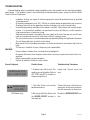
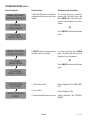
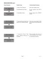
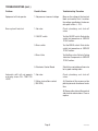
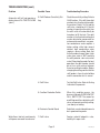
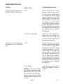
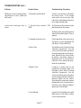
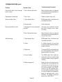
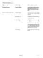
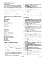
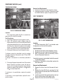
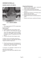
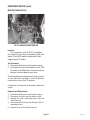
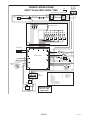
SYSTEM DBC ®
BREWERS
WITH SMART FUNNEL®
SERVICE & REPAIR MANUAL
BUNN-O-MATIC CORPORATION
POST OFFICE BOX 3227
SPRINGFIELD, ILLINOIS 62708-3227
PHONE: (217) 529-6601 FAX: (217) 529-6644
41746.0000A 11/08 ©2008 Bunn-O-Matic Corporation
BUNN-O-MATIC COMMERCIAL PRODUCT WARRANTY
Bunn-O-Matic Corp. (“BUNN”) warrants equipment manufactured by it as follows:
1) All equipment other than as specified below: 2 years parts and 1 year labor.
2) Electronic circuit and/or control boards: parts and labor for 3 years.
3) Compressors on refrigeration equipment: 5 years parts and 1 year labor.
4) Grinding burrs on coffee grinding equipment to grind coffee to meet original factory screen sieve analysis:
parts and labor for 3 years or 30,000 pounds of coffee, whichever comes first.
These warranty periods run from the date of installation BUNN warrants that the equipment manufactured by
it will be commercially free of defects in material and workmanship existing at the time of manufacture and
appearing within the applicable warranty period. This warranty does not apply to any equipment, component or
part that was not manufactured by BUNN or that, in BUNN’s judgment, has been affected by misuse, neglect,
alteration, improper installation or operation, improper maintenance or repair, damage or casualty. This warranty is
conditioned on the Buyer 1) giving BUNN prompt notice of any claim to be made under this warranty by telephone
at (217) 529-6601 or by writing to Post Office Box 3227, Springfield, Illinois 62708-3227; 2) if requested by
BUNN, shipping the defective equipment prepaid to an authorized BUNN service location; and 3) receiving prior
authorization from BUNN that the defective equipment is under warranty.
THE FOREGOING WARRANTY IS EXCLUSIVE AND IS IN LIEU OF ANY OTHER WARRANTY, WRITTEN OR
ORAL, EXPRESS OR IMPLIED, INCLUDING, BUT NOT LIMITED TO, ANY IMPLIED WARRANTY OF EITHER
MERCHANTABILITY OR FITNESS FOR A PARTICULAR PURPOSE. The agents, dealers or employees of BUNN
are not authorized to make modifications to this warranty or to make additional warranties that are binding on
BUNN. Accordingly, statements by such individuals, whether oral or written, do not constitute warranties and
should not be relied upon.
If BUNN determines in its sole discretion that the equipment does not conform to the warranty, BUNN, at its
exclusive option while the equipment is under warranty, shall either 1) provide at no charge replacement parts
and/or labor (during the applicable parts and labor warranty periods specified above) to repair the defective
components, provided that this repair is done by a BUNN Authorized Service Representative; or 2) shall replace
the equipment or refund the purchase price for the equipment.
THE BUYER’S REMEDY AGAINST BUNN FOR THE BREACH OF ANY OBLIGATION ARISING OUT OF THE SALE OF
THIS EQUIPMENT, WHETHER DERIVED FROM WARRANTY OR OTHERWISE, SHALL BE LIMITED, AT BUNN’S
SOLE OPTION AS SPECIFIED HEREIN, TO REPAIR, REPLACEMENT OR REFUND.
In no event shall BUNN be liable for any other damage or loss, including, but not limited to, lost profits, lost sales,
loss of use of equipment, claims of Buyer’s customers, cost of capital, cost of down time, cost of substitute
equipment, facilities or services, or any other special, incidental or consequential damages.
BrewWISE, BrewLOGIC, BrewMETER, BrewWIZARD, Bunn Gourmet, BUNN Gourmet Ice, BUNN Pour-O-Matic, BUNN,
Bunn-OMatic, Bunn-O-Matic, BUNNlink, BUNNserve, BUNNSERVE, BUNN Espress, DBC, Dr. Brew, Dual, EasyClear, EasyGard, Easy Pour, FlavorGard, Gourmet Ice, Gourmet Juice, High Intensity, IMIX, Infusion Series, Intellisteam, Quality Beverage Equipment Worldwide, The Mark of Quality in Beverage Equipment Worldwide, My Café, PowerLogic, Safety-Fresh,
Scale-Pro, Single, Smart Funnel, Smart Hopper, SmartWAVE, Soft Heat, SplashGard, System III, ThermoFresh, 392, AutoPOD, AXIOM, Beverage Profit Calculator, Beverage Bar Creator, BUNNsource, Coffee At Its Best, Cool Froth, Digital Brewer
Control, Nothing Brews Like a BUNN, Pouring Profits, Pulse Wave, Signature Series, Silver Series, Smart Heat, Tea At Its
Best, The Horizontal Red Line, Titan, Ultra, are either trademarks or registered trademarks of Bunn-O-Matic Corporation.
Page 2
41746 112008
TABLE OF CONTENTS
Warranty......................................................................................................................................2
Table of Contents.........................................................................................................................3
Troubleshooting...........................................................................................................................4
Service Tools..............................................................................................................................15
Component Access....................................................................................................................19
Control Board.......................................................................................................................19
Membrane Switch.................................................................................................................20
Dispense and Bypass Valves................................................................................................21
Refill Valves..........................................................................................................................22
Tank Heaters.........................................................................................................................24
Temperature Probe...............................................................................................................25
Limit Thermostats................................................................................................................25
Warmer Elements.................................................................................................................26
Master Power Switch............................................................................................................27
Schematic (Wiring Diagram)......................................................................................................28
Page 3
41746 112008
TROUBLESHOOTING
A troubleshooting guide is provided to suggest probable causes and remedies for the most likely problems
encountered. If the problem remains after exhausting the troubleshooting steps, contact the Bunn-O-Matic
Technical Service Department.
•
•
•
•
•
•
•
WARNING
•
•
•
•
Inspection, testing, and repair of electrical equipment should be performed only by qualified
service personnel.
All electronic components have 120 - 240 volt ac and low voltage dc potential on their terminals. Shorting of terminals or the application of external voltages may result in board failure.
Intermittent operation of electronic circuit boards is unlikely. Board failure will normally be permanent. If an intermittent condition is encountered, the cause will likely be a switch contact or
a loose connection at a terminal or crimp.
Solenoid removal requires interrupting the water supply to the valve. Damage may result if solenoids are energized for more than ten minutes without a supply of water.
The use of two wrenches is recommended whenever plumbing fittings are tightened or loosened.
This will help avoid twists and kinks in the tubing.
Make certain that all plumbing connections are sealed and electrical connections tight and isolated.
This brewer is heated at all times. Keep away from combustibles.
Exercise extreme caution when servicing electrical equipment.
Disconnect the brewer from the power source when servicing, except when electrical tests are specified.
Follow recommended service procedures.
Replace all protective shields or safety notices.
Screen Displayed
OVERFLOW CUP
FULL. EMPTY CUP
SERVER NOT
IN PLACE
(SH Models only)
Possible Cause
Troubleshooting Procedures
1. Overflow cup is full of water. This
could be caused by boiling. Refer to
SET TEMP and REFILL sections in
Programming Manual.
Empty cup. Correct cause and
retry.
1. Soft Heat Server not correctly
positioned on base.
Position the server so that the connector pins on the server make contact with connector on the brewer.
2. Not using a Soft Heat Server, and
the SERVER DETECT function is
activated (on).
Disable the SERVER DETECT function.
Page 4
41746 112008
TROUBLESHOOTING (cont.)
Screen Displayed
NO FUNNEL
PRESENT
TEMPERATURE
TOO LOW
CHECK FUNNEL
FOR FRESH COFFEE
Possible Cause
Troubleshooting Procedures
1. SMART FUNNEL not fully inserted
into the funnel rails.
Position the funnel so that the sensor
is directly beneath the sensor coil on
the brewer.
2. Not using a SMART FUNNEL,
and the FUNNEL DETECT function
is activated (on).
Disable the FUNNEL DETECT function.
1. Water temperature in the tank
does not meet the SET READY
TEMPERATURE.
(a) Wait for the brewer to heat to the
proper temperature.
1. Brew funnel was not removed
after the previous brew cycle was
finished.
Remove funnel, check contents, and
insert back into the funnel rails.
OR
Press BREW to start a brew cycle
without removing the funnel.
PRESS BREW
TO BREW ANYWAY
BREW STOPPED!
FUNNEL REMOVED?
(b) Disable the BREW LOCKOUT
function.
1. Brew funnel was moved out of
position after the brew cycle was
started.
TO FINISH:
PRESS BREW
To resume brewing, correctly position the funnel and press BREW
again. The brew cycle will resume
from the point it was interrupted.
OR
Press ON/OFF to terminate the
cycle.
TO CANCEL
PRESS ON/OFF
Page 5
41746 112008
TROUBLESHOOTING (cont.)
Screen Displayed
Possible Cause
Troubleshooting Procedures
BREW STOPPED!
SERVER REMOVED?
1. Soft Heat Server was moved out
of position after the brew cycle was
started.
To resume brewing, correctly
position the Soft Heat Server and
press BREW again. The brew cycle
resumes from the point it was interrupted.
TO FINISH:
PRESS BREW
OR
Press ON/OFF to terminate the brew
cycle.
TO CANCEL
PRESS ON/OFF
BREW STOPPED!
IS SWITCH OFF?
1. ON/OFF switch was pressed after
the brew cycle was started.
To resume brewing, press BREW
again. The brew cycle resumes form
the point it was interrupted.
OR
TO FINISH:
PRESS BREW
Press ON/OFF to terminate the brew
cycle.
TO CANCEL
PRESS ON/OFF
HEATING TIME
TOO LONG
CHECK HEATING
CIRCUIT
1. Tank Heater failure
Service Required. See TANK HEATERS.
2. Triac Failure
Service Required. See
3. Control Board/Thermistor failure
Service Required. See CONTROL
BOARD
Page 6
41746 112008
TROUBLESHOOTING (cont.)
Possible Cause
Troubleshooting Procedures
1. Water shut off to brewer
Check water supply shut-off
2. Inlet Solenoid Valve failure
Service required. See REFILL
VALVE.
CHECK WATER
SUPPLY
3. Control Board Failure
Service required. See CONTROL
BOARD.
TEMP SENSOR
OUT OF RANGE
1. Temperature Sensor Probe wire(s)
broken or not making connection.
Check wire and connection of both
black and white wires of temperature
probe.
1. Temperature Sensor Probe
wire(s) shorted to housing, or to
each other.
Check to confirm that wire(s) are
not pinched between two surfaces
or connected to each other.
Screen Displayed
FILL TIME TOO
LONG
CHECK FOR BAD
CONNECTIONS
TEMP SENSOR
OUT OF RANGE
CHECK WIRE FOR
SHORTS
Page 7
41746 112008
TROUBLESHOOTING (cont.)
Problem
Possible Cause
Troubleshooting Procedure
Equipment will not operate.
1. No power or incorrect voltage.
Measure the voltage at the terminal
block and confirm that it matches
the voltage specified on the brewer
data plate within +/- 10%.
Brew cycle will not start.
1. No water
Check plumbing and shut-off
valves
2. ON/OFF switch
Test the ON/OFF switch. Refer to the
switch test procedures in SERVICE
TOOLS section.
3. Brew switch
Test the BREW switch. Refer to the
switch test procedures in SERVICE
TOOLS section.
4. Brew Valve
Test the Brew valve. Refer to Testing
Individual Components in SERVICE
TOOLS section.
5. Electronic Control Board
Substitute a control board known to
be in good working order.
1. No water
Check plumbing and shut-off
valves.
2. Water strainer/flow control
(.750 GPM)
(A) Direction of flow arrow must be
pointing towards direction of water
flow.
Automatic refill will not operate
or display shows FILL TIME TOO
LONG
(B) Remove the strainer/flow control
and check for obstructions. Clear or
replace.
Page 8
41746 112008
TROUBLESHOOTING (cont.)
Problem
Possible Cause
Troubleshooting Procedure
Automatic refill will not operate or
display shows FILL TIME TOO LONG
(cont.)
3. Refill Probe or Sensitivity Setting
Check the sensitivity setting. Refer to
Refill function. If the left three digit
number is less than the right number,
the machine “thinks” it is full and the
refill valve should be off. If the left
number is larger than the right, then
the refill valve will automatically be
turned on to fill the tank. The right
number is the threshold setting and
can be adjusted to compensate for
extreme water conditions: very pure,
low conductance water requires a
higher setting, while high mineral
content, high conductance water
requires a lower setting. Note that
the left number changes from a high
value when water is NOT touching
the refill probe to a low value when
water IS touching the probe. For best
operation, the right number should
be set to a value midway between
these low and high numbers. Before
changing the setting, confirm that the
refill probe is free of scale buildup
and the connection to it is secure.
4. Refill Valve
Test the Refill valve. Refer to Testing
Individual Components.
5. Overflow Protection Switch
When this condition occurs, the
brewer will display OVERFLOW CUP
FULL. EMPTY CUP. The reason for
overfilling could be a defective refill
valve, an incorrect sensitivity setting,
(see above) or boiling.
6. Electronic Control Board
Substitute a control board known to
be in good working order.
1. Refill valve
Foreign material lodged in valve,
holding it in open state.
Water flows into tank continuously
with power removed from brewer.
Page 9
41746 112008
TROUBLESHOOTING (cont.)
Power
Possible Cause
Troubleshooting Procedures
Water flows into tank continuously
with power applied to brewer.
1. Refill Probe or Sensitivity Setting
Check the sensitivity setting. Refer to
Refill function. If the left three digit
number is less than the right number,
the machine “thinks” it is full and the
refill valve should be off. If the left
number is larger than the right, then
the refill valve will automatically be
turned on to fill the tank. The right
number is the threshold setting and
can be adjusted to compensate for
extreme water conditions: very pure,
low conductance water requires a
higher setting, while high mineral
content, high conductance water
requires a lower setting. Note that
the left number changes from a high
value when water is NOT touching
the refill probe to a low value when
water IS touching the probe. For best
operation, the right number should
be set to a value midway between
these low and high numbers. Before
changing the setting, confirm that the
refill probe is free of scale buildup
and the connection to it is secure.
2. Electronic Control Board
Substitute a control board known to
be in good working order.
1. Limit Thermostat
Remove power from the brewer.
Press reset button on limit thermostat. Then check for continuity
through it.
Water will not heat or display shows
HEATING TIME TOO LONG
CAUTION - Do not eliminate or
bypass limit thermostat. Use only
replacement part #23717.0003.
2. Tank Heaters
Page 10
Remove power from the brewer.
Check for continuity through the
tank heaters.
41746 112008
TROUBLESHOOTING (cont.)
Problem
Possible Cause
Troubleshooting Procedures
Water will not heat or display shows
HEATING TIME TOO LONG (cont.)
3. Triac
Remove power from the brewer.
Connect a voltmeter across one of
the tank heaters. Reapply power
to the brewer and refer to Testing
Individual Components. If the full
supply voltage is measured when
the tank heater is turned on, and
zero voltage is measured with the
triac off, then the triac is good. If
half the supply voltage is measured,
the triac is defective. If very low, or
zero voltage is measured, there could
be a defective triac or a defective
control board.
4. Electronic Control Board
Perform the above procedure for
testing triacs. If the voltage measured is very low or zero, then
substitute a control board known to
be in good working order.
1. Triac
Remove power from the brewer.
Connect a voltmeter across one of
the tank heaters. Reapply power
to the brewer and refer to Testing
Individual Components. If the full
supply voltage is measured when
the tank heater is turned on, and
zero voltage is measured with the
triac off, then the triac is good. If
half the supply voltage is measured,
the triac is defective. If very low, or
zero voltage is measured, there could
be a defective triac or a defective
control board.
2. Lime Buildup
Inspect the tank assembly for excessive lime deposits. Delime as
required.
Spitting or unusual steaming from
sprayhead or air vents. (Water too
hot)
CAUTION - Tank and tank components should be delimed regularly
depending on local water conditions. Excessive mineral buildup on
stainless steel surfaces can initiate
corrosive reactions resulting in serious leaks.
Page 11
41746 112008
TROUBLESHOOTING (cont.)
Problem
Possible Cause
Troubleshooting Procedures
Spitting or unusual steaming from
sprayhead or air vents. (Water too
hot) (cont.)
3. Electronic control board
Perform the previous procedure
for testing triacs. If the voltage
measured is very low or zero, then
substitute a control board known to
be in good working order.
Inconsistent beverage level in
server.
1. Strainer/flow control (.750
GPM)
(A) Direction of flow arrow must be
pointing towards the brewer.
(B) Remove the strainer/flow control
and check for obstructions. Clear or
replace.
2. Improper water pressure
Check operating water pressure to
the brewer. It must be between 20
and 90 psi (138 and 620 kPa).
3. Brew Valve
Test the Brew Valve. Refer to Testing
Individual Components. Turn the
valve on for 30 seconds and collect
the water dispensed from the sprayhead. Repeat the test several times
to confirm a consistent volume of
dispensed water. If not consistent,
check the valve, tubing and sprayhead for lime buildup.
4. Bypass Valve
If bypass is being used on the
inconsistent brewing recipe, test
the Bypass Valve. Refer to Testing
Individual Components. Turn the
valve on for 30 seconds and collect
the water collected from the bypass
opening. Repeat the test several
times to confirm a consistent volume
of dispensed water. If not consistent,
check the valve, tubing and bypass
opening for lime buildup.
5. Lime buildup
Inspect for lime buildup that could
block the tank, tank fittings, tubing,
valves and sprayhead.
Page 12
41746 112008
TROUBLESHOOTING (cont.)
Problem
Possible Cause
Troubleshooting Procedures
Consistently high or low beverage
level in server.
1. Brew Volume adjustment
Adjust the brew volume as required
to achieve the recommended volume
for each brew cycle.
Dripping from sprayhead.
1. Brew Valve
Repair or replace leaky valve.
Water overflows filter.
1. Type of paper filters
BUNN paper filters should be used
for proper extraction.
2. No sprayhead
Check sprayhead
1. Beverage left in server from previous brew
The brew cycle should be started
only with an empty server under
the funnel.
2. Brew Volume adjustment
Adjust the brew volume as required
to achieve the recommended volume
for each brew cycle.
1. Type of paper filters
BUNN paper filters should be used
for proper extraction.
2. Coffee
A sufficient quantity of fresh drip
or regular grind should be used for
proper extraction.
3. Sprayhead
The correct B.O.M. sprayhead should
be used to properly wet the bed of
ground coffee in the funnel.
4. Funnel Loading
The BUNN paper filter should be
centered in the funnel and the bed
of ground coffee leveled by gentle
shaking.
5. Water temperature
Empty the server, remove its cover,
and place the server beneath the
sprayhead. Place empty funnel over
the server entrance, with ON/OFF
switch in the "ON" position press
the start switch and release it. Check
the water temperature immediately
below the sprayhead with a thermometer. The reading should not
be less than 195˚F (91˚C).
Page 13
41746 112008
Beverage overflows server.
Weak beverage.
TROUBLESHOOTING (cont.)
Problem
Possible Cause
Troubleshooting Procedures
Weak beverage (cont.)
6. Incorrect Recipe
Consider adjusting bypass percentage, preinfusion, or pulse brew.
Contact Bunn-O-Matic for suggestions.
Brewer is making unusual noises.
1. Solenoid (Inlet)
The nut on back of the solenoid
must be tight or it will vibrate during
operation
2. Plumbing lines
Plumbing lines should not be resting
on the counter top.
3. Water Supply
(A) The brewer must be connected
to a cold water line.
(B) Water pressure to the brewer
must not be higher than 90 psi (620
kPa). Install a regulator if necessary
to lower the working pressure to approximately 50 psi (345 kPa).
4. Tank Heaters.
Page 14
Remove and clean lime off tank
heaters.
41746 112008
TROUBLESHOOTING (cont.)
SERVICE TOOLS
This function allows the testing of individual components and the ability to check switches for proper
function. This function also tests the Soft Heat server's
status on the brewer (in place or removed), and the
funnel sensor coil's frequency (diagnostic tool for
troubleshooting purposes only).
Testing individual components (outputs):
This will allow the operator to test the operation
of individual components and outputs of the brewer.
The components that can be individually tested are as
follows:
SINGLE Brewers
Brew Valve
Bypass Valve
Funnel Lock (Optional)
Server (SH models only)
Refill Valve
Tank Heaters
Heater Contactor
DUAL Brewers
Left Brew Valve
Left Bypass
Left Funnel Lock (Optional)
Left Server (SH models only)
Right Brew Valve
Right Bypass
Right Funel Lock (Optional)
Right Server (SH models only)
Refill Valve
Tank Heaters
Heater Contactor
6. Press and release YES. The display should read:
BREW VALVE on SINGLE brewers
LEFT BREW VALVE on DUAL brewers.
7. To test BREW VALVE, press ON. If the brew valve
is functional, water should run from the brewer
(left side on DUAL brewers)
8. Press OFF to end flow of water.
9. Press NEXT to advance to the next component to
be tested.
NOTE: To bypass testing any component, press NEXT
to advance to the next one, without testing the previous component.
10.To test BREW BYPASS on SINGLE brewers or LEFT
BREW BYPASS on DUAL brewers, press ON. If the
bypass valve is functional, water should run from
the brew bypass (left side on DUAL brewers).
11.Press OFF to end flow of water.
12.Press NEXT to advance to the next component to
be tested.
13.To test FUNNEL LOCK on SINGLE brewers or LEFT
FUNNEL LOCK on DUAL brewers, press ON. If the
funnel lock is functional, the lock will come down
to hold the funnel in place.
14.Press OFF to retract the funnel lock.
15.Press NEXT to advance to the next component to
be tested.
16.(SH models only) To test SERVER on SINGLE
brewers or LEFT SERVER on DUAL brewers, press
ON. If the server and the sensor are functional, the
light on the lower right corner of the server will
illuminate.
17.Press OFF to end testing of server.
18.Press NEXT to advance to the next component to
be tested.
19.For DUAL brewers, follow steps 7 through 16 to
test the right side components.
20.To test REFILL VALVE, press ON. If the refill valve
is functional, the sound of the valve operating will
be heard.
21.Press OFF to end testing of refill valve.
22.Press NEXT to advance to the next component to
be tested.
23.To test TANK HEATERS, connect a voltmeter across
each of the tank heaters to check for voltage.
24.Press ON. The correct voltage should be present
at the heater terminals.
25.Press OFF to end testing of the tank heaters.
Procedure to test components (outputs):
1. Place brew funnel(s) into rails on the brewer (both
sides on DUAL brewers).
2. Place server(s) beneath the brew funnel(s).
3. Press and hold the upper right hidden switch until
display reads UNITS. Release the switch. Continue
to press and release switch until SERVICE TOOLS
appears.
4. Press YES to run tests on various components
and outputs within the brewer. Pressing NO will
exit this function and advance to next function
screen.
5. The display should read TEST OUTPUTS.
Page 15
41746 112008
TROUBLESHOOTING (cont.)
SERVICE TOOLS (cont.)
SERVICE TOOLS?
NO
YES
EXIT TO
NEXT FUNCTION
SCREEN
TEST OUTPUTS?
NO
YES
TEST SWITCHES?
NO
YES
PRESS AND RELEASE
® SYMBO L
SINGLE
BREWERS
DUAL
BREWERS
BREW VALVE
ON NEXT OFF
LEFT BREW VALVE
ON NEXT OFF
BYPASS
NEXT OFF
LEFT BYPASS
ON NEXT OFF
NOTHING PRESSED
ON
TEST SERVERS?
NO
YES
SINGLE
BREWERS
SERVER REMOVED
FUNNEL LOCK
ON NEXT OFF
LEFT FUNNEL LOCK
ON NEXT OFF
DUAL
BREWERS
<- SERVER REMOVED
IN PLACE ->
TEST FREQUENCY?
NO
YES
SERVER
NEXT OFF
LEFT SERVER
ON NEXT OFF
REFILL VALVE
ON NEXT OFF
RIGHT BREW VALVE
ON NEXT OFF
TANK HEATRS
ON NEXT OFF
RIGHT BYPASS
ON NEXT OFF
HEATER CONTACTOR
ON NEXT OFF
RIGHT FUNEL LOCK
ON NEXT OFF
ON
PRESS AND RELEASE
® SYMBOL
SINGLE
BREWERS
125.0 KHZ. 4
DUAL
BREWERS
<-<-<- 125.0 KHZ. 4
4 125.0 KHZ ->->->
EXIT TO
NEXT FUNCTION
SCREEN
PRESS AND RELEASE
® SYMBOL
RIGHT SERVER
ON NEXT OFF
Page 16
41746 112008
TROUBLESHOOTING (cont.)
SERVICE TOOLS (cont.)
to TEST SWITCHES?. Press and release switch
again to advance to TEST SERVERS?. Another
alternative is to press and release the ON/OFF
switch (either on DUAL brewers) located on the
front switch panel. This will exit TEST SWITCHES
and return to the MAIN SCREEN.
NOTE: The tank heater will automatically turn off if
left on too long.
26.After testing the tank heater, press NEXT to advance
to the next test.
27.The HEATER CONTACTOR is used only on certain
models. Check the machine schematic to see if the
contactor is present. Connect a voltmeter across a
tank heater that is operated by the contactor and
press ON to check that correct voltage is present.
Press OFF and confirm the voltage is zero.
28.Press NEXT to return to TEST OUTPUTS.
29.To exit SERVICE TOOLS, press and release the
ON/OFF switch (either on DUAL brewers) located
on the front switch panel. This will return to the
MAIN SCREEN.
Procedure to test switches:
This function allows the operator to test the operation of the individual switches on the front panel.
1. Place brew funnel(s) into rails on the brewer (both
sides on DUAL brewers).
2. Place server(s) beneath the brew funnel(s).
3. Press and hold the upper right hidden switch until
display reads UNITS. Release the switch. Continue
to press and release switch until SERVICE TOOLS
appears.
4. Press YES to run tests on various components
and outputs within the brewer. (Pressing NO will
exit this function and advance to the next function
screen.)
5. The display should read TEST OUTPUTS.
6. In TEST OUTPUTS screen, press NO. This advances
to TEST SWITCHES.
7. Pressing NO in this screen will advance to the
next function. Press YES in the TEST SWITCHES
screen to test the switches. The display will read
NOTHING PRESSED.
8. From this screen, press any of the switches on the
front of the brewer except the upper right hidden
switch. While the switch is pressed, the display
shows the name of that switch. If the name does
not appear, or if it remains after the switch has been
released, the switch is defective. Each switch can
be tested in this manner.
9. After all switches have been tested, press and release the right hidden switch (®). This will return
Procedures to test servers: (SH models only)
This function allows the operator to test the operation of the Soft Heat servers. It will also show if the
server is correctly placed on the brewer stand.
1. Place brew funnel(s) into rails on the brewer (both
sides on DUAL brewers).
2. Place a Soft Heat server(s) beneath the brew
funnel(s).
3. Press and hold the upper right hidden switch until
the display reads UNITS. Release the switch. Continue to press and release switch until SERVICE
TOOLS? appears.
4. Pressing NO will exit this function and advance to
the next function screen. Press YES to run tests
on various components and outputs within the
brewer.
5. The display should read TEST OUTPUTS?
6. In TEST OUTPUTS screen, press NO. This advances to TEST SWITCHES?. Press and release
NO once more. The display should now read TEST
SERVER(S)?
7. Press YES in the TEST SERVER(S) screen to show
if a server is in place. The display should read IN
PLACE (with arrows pointing to the left and right
on DUAL brewers).
8. Lift and pull both Soft Heat servers forward about
2 inches so that the two contacts on each server
do not touch the two contacts on the brewer.
9. The display should then read SERVER REMOVED
(with arrows pointing to the left and right on DUAL
brewers).
10.After the server(s) have been tested, press and release the ON/OFF switch (either on DUAL brewers)
located on the front switch panel. This will exit TEST
SERVERS and return to the MAIN SCREEN.
Procedures to test coil frequency:
1. Place brew funnel(s) into rails on the brewer (both
sides on DUAL brewers).
2. Place server(s) beneath the brew funnel(s).
Page 17
41746 112008
TROUBLESHOOTING (cont.)
SERVICE TOOLS (cont.)
3. Press and hold the upper right hidden switch until
the display reads UNITS. Release the switch.
Continue pressing and releasing the upper right
hidden switch until SERVICE TOOLS appears.
4. Pressing NO will exit this function and advance to
the next function screen. Press YES to run tests
on various components and outputs within the
brewer.
5. The display should read TEST OUTPUTS?.
6. In TEST OUTPUTS screen, press NO. Continue
to press and release NO until the display reads
TEST FREQUENCY?.
7. Press and release YES. The display will show the
frequency of the sensor coil circuits. This is for
diagnostic service use when troubleshooting this
circuit.
8. After the coils have been tested, press and release
the ON/OFF switch (either on DUAL brewers)
located on the front switch panel. This will exit
the TEST FREQUENCY function and return to the
MAIN SCREEN.
NOTE: If the operator wishes to test more than one
function in the SERVICE TOOLS section (outputs,
switches, servers, or coil frequency), it is not
necessary to exit the program. Use the flow chart
for SERVICE TOOLS to navigate to a particular
function.
Page 18
41746 112008
CONPONENT ACCESS
This section provides procedures for testing and
replacing various major components used in this
brewer should service become necessary. Refer to
Troubleshooting for assistance in determining the
cause of any problem.
WARNING - Inspection, testing, and repair of electrical equipment should be performed only by qualified
service personnel. The brewer should be disconnected
from power source when servicing, except when
electrical tests are required and the test procedure
specifically states to plug in the brewer.
WARNING - Disconnect the brewer from the power
source before the removal of any panel or the replacement of any component.
All components are accessible by the removal of
the top cover, front access panel and platform cover.
Refer to wiring diagrams at the back of this manual
when reconnecting wires.
CONTROL BOARD
Control Board Mounting Nut
If no voltage is present, check wiring to the board.
If voltage is present, and brewer does not power on,
replace board.
Removal and Replacement:
1. Disconnect brewer from power source.
2. Disconnect the funnel sensor(s) from connector
J9 on the control board.
3. Disconnect the main harness from connector J11
on the control board.
4. Disconnect the ribbon cable from connector J4 on
the control board.
5. Disconnect the level probe harness and server
detect harness for SH models from connector J2
on the control board.
6. Remove the two mounting nuts securing the top
of the control board to the hood.
7. Tilt the control board inward to clear the display
section and lift out of the control board mount.
8. Place the bottom edge of the new control board
in the control board mount, tilt the board forward,
and secure with the two keps nuts.
9. Re-connect wires to the circuit board.
Ribbon Cable
Control Board Mount
FIG 1 CONTROL BOARD MOUNTING
Location:
The Control Board (Fig 1) is located under the top
cover behind the control panel.
Check for Power to board:
1. Insert one meter lead in J11-pin 12 and the other
lead in J11-pin 14.
2. With the power connected to brewer, the voltage
reading to the board should be the line voltage
rated for that model.
Page 19
41746 112008
CONPONENT ACCESS (cont)
4. Remove any adhesive that remains on the hood.
5. Remove the adhesive backing from the new membrane switch. Insert the ribbon cable through the
slot in the hood and apply the membrane switch
to the front of the hood.
6. Reconnect the ribbon cable to the 20-pin connector on the control board making sure every pin on
the control board is inserted into the ribbon cable
connector.
MEMBRANE SWITCH
Funnel Sensor
FIG 2 MEMBRANE SWITCH
Location:
The Membrane Switch (Fig 2) is located on the front
of the hood with a ribbon cable extending through the
hood and connected to the control board.
Test Procedures:
There are two methods for testing the membrane
switch. The easiest method is to use the built in test
mode. Refer to the Trouble Shooting Section for Service
Tools/Test Switches. If for some reason you can't get
into the program modes, or brewer won't power up,
you can test it with an ohmmeter or continuity tester.
Refer to the schematic to trace the appropriate pins.
NOTE: Pin 1 is the static shield & will not provide a
reading to the other pins. There are three commons
in this circuit, pins #2, 11 & 12.
Disconnect brewer from power source before disconnecting ribbon cable from control board.
Removal and Replacement:
1. Disconnect the ribbon cable from 20-pin connector
on the control board.
2. Disconnect the wires from funnel sensor(s)and
remove sensor(s) from the front of the hood.
3. Gently peel the membrane switch from the
hood.
Page 20
41746 112008
CONPONENT ACCESS (cont)
If the polarity of meter leads are reversed, reading
will indicate -170VDC. (Double these readings for
240 volt coils)
DISPENSE & BYPASS VALVES
If voltage is present as described, but no coil action
is observed, valve is defective. Replace valve and test
again to verify repair.
If voltage is not present as described, refer to Wiring Diagrams and check the brewer wiring harness.
Also check the control board and switch for proper
operation.
FIG 3 DISPENSE & BYPASS VALVES
Location:
The dispense and bypass valve(s) (Fig 3) are located
inside the hood under the top cover.
Test Procedures:
1. Refer to the Trouble Shooting Section for Service
Tools/Test Outputs/Dispense/Bypass Valve.
2. Be sure brew funnel & server are in place before
activating valve.
3. Check the valve for coil action. Turn on the valve
with the test mode. Listen carefully in the vicinity
of the dispense/bypass valve for a click as the coil
pulls the plunger in.
If no sound is heard as described, proceed to
#4.
If the sound is heard as described, there may be a
blockage in the valve , hose, tank, or sprayhead. Disconnect the brewer from the power source. Remove
the valve and inspect for blockage, and de-lime all
related areas.
Removal and Replacement:
1. Disconnect the brewer from the power source.
2. Disconnect wires from the valve.
3. Drain enough water from the tank so the water
level is below the outlet.
4. Remove tube(s) from the valve.
5. Dispense valve:
Remove the sprayhead and nut securing valve to
the sprayhead panel.
Bypass valve:
Remove the two #8-32 mounting nuts.
6. Install new valve using nut(s) removed in step 5.
Clean and install the sprayhead.
7. Reconnect tube(s) to the valve and secure in place
with clamp(s).
4. Connect the voltmeter leads to the coil terminals.
Turn on the valve with the test mode. NOTE: Due
to the internally rectified coil, the indication will
be 120VAC all the time. Set the meter to DC volts.
The indication should be 170VDC when activated.
Page 21
41746 112008
CONPONENT ACCESS (cont)
REFILL VALVE
FIG 4 REFILL VALVE
(DUAL SH DBC Models)
FIG 6 REFILL VALVE
(DUAL TF DBC Early Models)
FIG 5 REFILL VALVE
(SINGLE SH DBC Models)
FIG 7 REFILL VALVE
(DUAL TF DBC Late Models)
Page 22
41746 112008
CONPONENT ACCESS (cont)
REFILL VALVE (cont)
If voltage is not present, refer to Wiring Diagrams
and check main wiring harness. If harness checks ok,
replace control board.
4. Check the refill valve for coil action. Briefly activate
the refill valve in the test mode and listen carefully
near the refill valve for a"clicking" sound as the
magnetic coil pulls the plunger in.
If the sound is heard as described and water will not
pass through the refill valve, there may be a blockage
in the water line before the refill valve or, the solenoid
valve may require inspection for wear, and removal of
waterborne particles.
If the sound is not heard as described, proceed to
# 5.
FIG 8 REFILL VALVE
(DUAL GPR DBC Models)
Location:
DUAL SH DBC models:
SINGLE TF DBC late models:
DUAL TF DBC late models:
The refill valve is located inside the front of the
brewer behind the front access panel.
SINGLE SH DBC models:
SINGLE GPR DBC models:
SINGLE TF DBC early models:
DUAL GPR DBC models:
DUAL TF DBC early models:
The refill valve is located inside the hood of the
brewer under the top cover.
Test Procedures:
1. Enter programming level 2, scroll to "Service Tools"
then scroll to "Refill Valve".
2. Briefly activate the refill valve in the test mode.
With a voltmeter, check the voltage across the coil
wires.
3. The indication must be 120 volts ac for two wire
120 volt models, three wire 120/208, and 120/240
volt models or 230 volts ac for two wire 230 volt
models.
5. Disconnect the brewer from the power source.
6. Check for continuity across the refill valve coil
terminals.
If continuity is not present as described, replace
the refill valve.
If continuity is present as described, there could
be some debris in the valve.
Removal and Replacement:
1. Shut off the water supply.
2. Remove both wires from the refill valve.
3. Disconnect both water lines at the valve.
4. Remove the two 1/4"-20 screws securing the valve
to the component mounting bracket.
5. Using the two 1/4"-20 screws, install the new valve
to the component mounting bracket.
6. Securely fasten the water lines to the valve.
7. Refer to wiring diagrams when reconnecting the
wires.
8. Install access panels and covers and refer to Initial
Set-up for refill and operation.
If voltage is present, proceed to # 4.
Page 23
41746 112008
CONPONENT ACCESS (cont)
TANK HEATERS
Location:
The tank heaters (Fig 9) are located inside the tank,
secured to the tank lid.
Tank Heaters
Test Procedures:
1. With a voltmeter, check voltage across the white
wire (120V Models) or red wire (120/208 and
120/240V Models) and blue wire on the top of
the tank heaters. Connect brewer to the power
source. The indication must be 120 volts ac for
two wire 120 volt models, 208 volts ac for three
wire 120/208 volt models and 240 volts ac for
120/240 volt models (during a heating cycle).
2. Disconnect the brewer from the power source.
If voltage is present as described, proceed to #3.
If voltage is not present as described, refer to the
Wiring Diagrams and check wiring harness. If harness
checks ok, replace control board.
3. Disconnect the wires from the tank heater terminals.
4. Check resistance value across tank heater terminals
and compare to chart.
If resistance is present as described, reconnect the
wires, the tank heater is ok.
If resistance is not present as described, replace the
tank heater.
FIG 9 TANK HEATERS
Removal and Replacement:
1. Remove the top cover from the brewer.
2. Disconnect the wires from tank heater terminals.
3. Remove the four #8-32 nuts securing the tank
heater(s) to the tank lid assembly.
4. Remove tank heater(s) with gasket(s) and discard.
5. Install new tank heater(s) with gasket(s) to the
tank lid assembly with the original nuts.
6. Reconnect the wires to the tank heater(s) terminals.
NOTE- If any resistance is read between sheath and
either terminal, remove and inspect heater for cracks
in the sheath.
HEATER
RESISTANCE
1800W-120V
8.05
2200W-120V
6.54
2850W-208V
15.25
3300W-240V
18.81
4000W-208V
11.0
4000W-240V
14.47
5000W-240V
11.65
TERMINAL TO SHEATH - INFINITE (OPEN)
Page 24
41746 112008
CONPONENT ACCESS (cont)
TEMPERATURE PROBE
Removal and Replacement:
1. Disconnect the brewer from the power source.
2. Refer to instructions included in Temperature Probe
Kit #29327.0000 to replace Temperature Probe.
LIMIT THERMOSTAT
Temperature Probe
Limit Thermostats
FIG 10 TEMPERATURE PROBE
Location:
The temperature probe (Fig 10) is inserted into a
grommet in the tank lid assembly.
Test Procedures:
1. Disconnect the brewer from the power source.
2. With a DC voltmeter, check voltage across the
black and white wires at J2 on control board (Black
voltmeter probe to black wire, red voltmeter probe
to white wire). Connect the brewer to the power
source. The indication should be aproximately between 4vdc cool to 1vdc at ready temperature.
3. Disconnect the brewer from the power source.
If voltage is present as described, circuit is working
correctly, check limit thermostat (and TCO on 200V
and 230V models).
If voltage is not present as described, proceed to
#4.
4. Disconnect temperature probe from J2 on control
board. Check the resistance across the two terminals of the temperature probe. The indication
should be aproximately between 10.5K cool to
870 at ready temperature.
FIG 11 LIMIT THERMOSTATS
Location:
The limit thermostats (Fig 11) are located under
the top cover on the tank lid assembly.
Test Procedures:
1. Disconnect the brewer from the power source.
2. Disconnect the wires from the limit thermostat.
3. With an ohmmeter, check for continuity across
the limit thermostat terminals.
If continuity is present as described, the limit thermostat
is operating properly.
If continuity is not present as described, replace the
limit thermostat.
Removal and Replacement:
1. Remove the wires from limit thermostat terminals.
2 Remove the two #8-32 nuts securing the limit
thermostat to the tank lid and lift limit thermostat
If resistance is to specification, replace the control
off the studs.
board.
3. Install the new limit thermostat onto the studs on
If resistance is not to specification, replace the temthe tank lid and secure with original nuts.
perature probe.
4. Connect the wires to the limit thermostat.
41746 112008
Page 25
CONPONENT ACCESS (cont)
WARMER ELEMENTS (GPR MODELS)
Removal and Replacement:
1. Remove the three #4-40 screws securing the
warmer assembly to the brewer.
2. Lift the warmer assembly from the brewer.
3. Disconnect the two wires from the warmer element
terminals.
4. Remove the two #8-32 nuts securing the warmer
element to the warmer plate.
5. Securely install new warmer element.
6. Reconnect the two wires to warmer element terminals.
7. Securely install warmer assembly on the brewer.
FIG 12 WARMER ELEMENTS
Location:
The warmer element(s) (FIG 12) is located under
the warmer plate(s).
Test Procedures:
1. Disconnect the brewer from the power source.
2. With a voltmeter, check voltage across the two
wires at the warmer element with the "ON/OFF"
switch in the "ON" position. Connect the brewer
to the power source. The indication must be 120
volts ac.
3. Disconnect the brewer from the power source.
If voltage is present as described, proceed to #4.
If voltage is not present as described, refer to Wiring
Diagrams and check wiring harness.
4. Check the resistance across the two terminals on
warmer element. Resistance should be 144.0 ,
terminal to sheath - infinite (open).
If resistance is to specification, reconnect the two
wires to the warmer element.
If resistance is not to specification, replace the warmer
element.
Page 26
41746 112008
CONPONENT ACCESS (cont)
MASTER POWER SWITCH
FIG 13 MASTER POWER SWITCH
Location:
The main power switch (FIG 13) is located under the brewer in the base just behind the right front
leg on SH and GPR models and behind the front
support leg on TF models.
Test Procedure:
1. Disconnect the brewer from the power source.
2. Disconnect the wires from the power switch. With
the switch in the ON position, check for continuity
between terminals opposite each other.
There should be continuity between the two terminals
on each side when the switch is in the ON position,
no continuity when in the OFF position.
If continuity is not present as described, replace the
switch.
Removal and Replacement:
1. Disconnect the brewer from the power source.
2. Disconnect the wires from the power switch.
3. Remove the switch mounting screws from the
under the base.
4. Install new switch in trunk with the two 6-32 x ¼˝
mounting screws.
5. Connect wires to the switch terminals.
Page 27
41746 112008
WHI
BLK
GRN
L2
RED
L1 N
SCHEMATIC WIRING DIAGRAM
SINGLE® SH with SMART FUNNEL® (DBC)
LIMIT THERMOSTAT
BLK-14
BLK-14
MT 1 BLU -14
MT2
BLK-14
BLK-14
BLK-14
RED-14
RED-14
RED-14
WHI
MODELS WITH MAIN ON/OFF SWITCH ONLY
TANK HEATER
TRIAC
SWITCH UNIT ASSY
SHIELD
FUNNEL SENSOR
VIO
WHI/VIO
VIO
SOL
WHI/GRN
CONTROL PC BOARD
GRY
WHI/VIO
WHI
WATER LEVEL
PROBE
TEMP
PROBE
SOL
SOL
BREW
RED
TAN
YEL
BLK
PNK
BLK
BLK
WHI/RED
WHI
REFILL
BYPASS
RED
N.C.
OVERFLOW
PROTECTION SWITCH
WHI
WHI
BRN/WHI
BRN/BLK
GRN
WHI
WHI
SOL
FUNNEL LOCK
(OPTIONAL)
WHI
BLK WHI
Touch Switch Assembly Codes
SERVER
TRANSFORMER
BLU/BLK
4
AMP
BLU/BLK
RED
AC
–
RECTIFIER
+
AC
24VDC
+
–
A1
A2
B1
B2
C1
C2
C3
D1
D2
D3
Brew
On/Off
"Hidden" Left
"Hidden" Right
Large Batch
Medium Batch
Small Batch
"Digital" Left Hidden Button
"Brewer" Center Hidden Button
"Control" Right Hidden Button
LED's
L1
L2
L3
L4
Large Batch LED
Medium Batch LED
Small Batch LED
On/Off LED
BLK
120/208 OR 120/240
VOLT A.C. + GND
SINGLE PHASE
32043.0000D 01/07 © 2000 BUNN-O-MATIC CORPORATION
White Strip-Tac Plus
Black Ink
Finished Size: 7.0" x 8.5"
~78% Reduction
Page 28
41746 112008
SCHEMATIC WIRING DIAGRAM
SINGLE SH DBC (W/SMART FUNNEL)
L1
L2
GRN/YEL
BLK
RED
EMI
FILTER
RED
BLK
LIMIT THERMOSTAT
BLK-14
TRIAC
BLK-14
MT 1 BLU -14
MT2
THERMAL
SAFETY FUSE
THERMAL
SAFETY FUSE
RED
TANK HEATER
BLK
TOUCH SWITCH ASSMBLE
L2
L1
L4
L3
C1
C2
D1
C3
D2
A1
VIO
D3
A2
SOL
B1
WHI
REFILL
WHI/GRN
GRY
WHI/VIO
B2
SOL
SOL
BREW
RED
TAN
YEL
BLK
BYPASS
WHI
RED
RED
N.C.
OVERFLOW
PROTECTION SWITCH
RED
BRN/WHI
BRN/BLK
RED
SOL
FUNNEL LOCK
(OPTIONAL)
BLK
RED
SERVER
TRANSFORMER
BLU/BLK
4
AMP
RESETTABLE
FUSE
BLU/BLK
230 VOLT AC
2 WIRE
SINGLE PHASE
50HZ
RED
AC
–
RECTIFIER
+
AC
BLK
24VDC
+
–
Touch Switch Assembly Codes
A1
A2
B1
B2
C1
C2
C3
D1
D2
D3
Brew
On/Off
"Hidden" Left
"Hidden" Right
Large Batch
Medium Batch
Small Batch
"Digital" Left Hidden Button
"Brewer" Center Hidden Button
"Control" Right Hidden Button
LED's
L1
L2
L3
L4
Large Batch LED
Medium Batch LED
Small Batch LED
On/Off LED
32043.0001B 07/05 © 2002 BUNN-O-MATIC CORPORATION
NOT A PURCHASED SCHEMATIC
FOR REFERENCE
Page 29 ONLY
41746 112008
SCHEMATIC WIRING DIAGRAM
SINGLE SH DBC (W/SMART FUNNEL)
L1
L2
GRN/YEL
BLK
RED
EMI
FILTER
RED
BLK
LIMIT THERMOSTAT
BLK-14
TRIAC
BLK-14
MT 1 BLU -14
MT2
THERMAL
SAFETY FUSE
THERMAL
SAFETY FUSE
RED
TANK HEATER
BLK
TOUCH SWITCH ASSMBLE
L2
L1
L4
L3
C1
C2
D1
C3
D2
A1
VIO
D3
A2
SOL
B1
WHI
REFILL
WHI/GRN
GRY
WHI/VIO
B2
SOL
SOL
BREW
RED
TAN
YEL
BLK
BYPASS
WHI
RED
RED
N.C.
OVERFLOW
PROTECTION SWITCH
RED
BRN/WHI
BRN/BLK
RED
SOL
FUNNEL LOCK
(OPTIONAL)
BLK
RED
SERVER
TRANSFORMER
BLU/BLK
4
AMP
RESETTABLE
FUSE
BLU/BLK
200 VOLT AC
2 WIRE
SINGLE PHASE
50/60HZ
RED
AC
–
RECTIFIER
+
AC
BLK
24VDC
+
–
Touch Switch Assembly Codes
A1
A2
B1
B2
C1
C2
C3
D1
D2
D3
Brew
On/Off
"Hidden" Left
"Hidden" Right
Large Batch
Medium Batch
Small Batch
"Digital" Left Hidden Button
"Brewer" Center Hidden Button
"Control" Right Hidden Button
LED's
L1
L2
L3
L4
Large Batch LED
Medium Batch LED
Small Batch LED
On/Off LED
32043.0002B 07/05 © 2004 BUNN-O-MATIC CORPORATION
NOT A PURCHASED SCHEMATIC
FORPage
REFERENCE
ONLY
30
41746 112008
SCHEMATIC WIRING DIAGRAM
SINGLE® SH with SMART FUNNEL® (DBC)
L1
B
L
K
N
TRIAC
LIMIT THERMOSTAT
BLK-14
BLK-14
MT 1 BLU -14
MT2
WHI-14
W
H
I
TANK HEATER
SWITCH UNIT ASSY
SHIELD
FUNNEL SENSOR
VIO
WHI/VIO
VIO
SOL
WHI/GRN
CONTROL PC BOARD
GRY
WHI/VIO
WHI
WATER LEVEL
PROBE
TEMP
PROBE
SOL
SOL
BREW
RED
TAN
YEL
BLK
PNK
BLK
BLK
WHI/RED
WHI
REFILL
BYPASS
RED
N.C.
OVERFLOW
PROTECTION SWITCH
WHI
WHI
BRN/WHI
BRN/BLK
GRN
WHI
WHI
SOL
FUNNEL LOCK
(OPTIONAL)
WHI
BLK WHI
SERVER
TRANSFORMER
4
AMP
BLU/BLK
120 VOLT A.C.
2 - WIRE
SINGLE PHASE
RED
AC
–
RECTIFIER
+
AC
Touch Switch Assembly Codes
A1
A2
B1
B2
C1
C2
C3
D1
D2
D3
BLU/BLK
24VDC
+
–
BLK
Brew
On/Off
"Hidden" Left
"Hidden" Right
Large Batch
Medium Batch
Small Batch
"Digital" Left Hidden Button
"Brewer" Center Hidden Button
"Control" Right Hidden Button
LED's
L1
L2
L3
L4
Large Batch LED
Medium Batch LED
Small Batch LED
On/Off LED
32043.0004B 07/05 © 2004 BUNN-O-MATIC CORPORATION
White Strip-Tac Plus
Black Ink
Finished Size: 5" x 6"
~55% Reduction
Page 31
41746 112008
BLK
WHI
L1 N
GRN
L2
RED
SCHEMATIC WIRING DIAGRAM
SINGLE SH DBC with SMART FUNNEL
(With Audible Alarm)
BLK-14
BLK-14
BLK-14
RED-14
RED-14
RED-14
WHI
MODELS WITH MAIN ON/OFF SWITCH ONLY
TRIAC
LIMIT THERMOSTAT
BLK-14
BLK-14
MT 1 BLU -14
MT2
TANK HEATER
SWITCH UNIT ASSY
AUDIBLE
ALARM
(FRESHNESS)
SHIELD
WHI
FUNNEL SENSOR
BLK
VIO
WHI/VIO
VIO
SOL
WHI/GRN
CONTROL PC BOARD
WHI
TEMP
PROBE
SOL
SOL
BREW
RED
TAN
YEL
BLK
PNK
BLK
WATER LEVEL
PROBE
GRY
WHI/VIO
BLK
WHI/RED
WHI
REFILL
BYPASS
RED
N.C.
OVERFLOW
PROTECTION SWITCH
WHI
WHI
BRN/WHI
BRN/BLK
GRN
WHI
WHI
SOL
FUNNEL LOCK
(OPTIONAL)
WHI
BLK WHI
SERVER
TRANSFORMER
BLU/BLK
4
AMP
BLU/BLK
120/208 VOLT A.C. OR
120/240 VOLT A.C.
3 WIRE + GND
SINGLE PHASE
RED
AC
–
RECTIFIER
+
AC
Touch Switch Assembly Codes
A1
A2
B1
B2
C1
C2
C3
D1
D2
D3
24VDC
+
–
BLK
Brew
On/Off
"Hidden" Left
"Hidden" Right
Large Batch
Medium Batch
Small Batch
"Digital" Left Hidden Button
"Brewer" Center Hidden Button
"Control" Right Hidden Button
LED's
L1
L2
L3
L4
Large Batch LED
Medium Batch LED
Small Batch LED
On/Off LED
32043.0005B 02/07 ©2006 BUNN-O-MATIC CORPORATION
White Strip-Tac Plus
Black Ink
Finished Size: 7" x 9"
~75% Reduction
Page 32
41746 112008
SCHEMATIC WIRING DIAGRAM
SINGLE SH DBC (W/SMART FUNNEL)
L1 L2
RED
BLK
GRN
MAIN ON/OFF SWITCH ONLY
(Late Models only)
RED-14
RED-14
RED-14
BLK-14
BLK-14
BLK-14
LIMIT THERMOSTAT
BLK-14
TRIAC
BLK-14
MT 1 BLU -14
MT2
RED
TANK HEATER
BLK
TOUCH SWITCH ASSMBLE
L2
L1
L4
L3
C1
C2
D1
C3
D2
A1
VIO
D3
A2
SOL
B1
WHI
REFILL
WHI/GRN
GRY
WHI/VIO
B2
SOL
SOL
BREW
RED
TAN
YEL
BLK
BYPASS
WHI
RED
RED
N.C.
OVERFLOW
PROTECTION SWITCH
RED
BRN/WHI
BRN/BLK
RED
SOL
FUNNEL LOCK
(OPTIONAL)
BLK
RED
SERVER
TRANSFORMER
BLU/BLK
Touch Switch Assembly Codes
4
AMP
BLU/BLK
200 VOLT AC
2 WIRE + GND
SINGLE PHASE
50/60HZ
RED
AC
–
RECTIFIER
+
AC
24VDC
+
–
BLK
A1
A2
B1
B2
C1
C2
C3
D1
D2
D3
Brew
On/Off
"Hidden" Left
"Hidden" Right
Large Batch
Medium Batch
Small Batch
"Digital" Left Hidden Button
"Brewer" Center Hidden Button
"Control" Right Hidden Button
LED's
L1
L2
L3
L4
Large Batch LED
Medium Batch LED
Small Batch LED
On/Off LED
32043.0006C 06/07 © 2007 BUNN-O-MATIC CORPORATION
White Strip-Tac Plus
Black Ink
FinishedPage
Size: 33
7" x 9"
~75% Reduction
41746 112008
SCHEMATIC WIRING DIAGRAM
DUAL SH with SMART FUNNEL (DBC)
WHI
RED
GRN
BLK
L1 N L2
BLK-14
BLK-14
RED-14
RED-14
WHI
MODELS WITH MAIN ON/OFF SWITCH ONLY
BLK-14
RED-14
RED-14
RED-14
120/208 OR 120/240
VOLT A.C. + GND
SINGLE PHASE
29876.0000D 01/07 © 2001 BUNN-O-MATIC CORPORATION
White Strip-Tac Plus
Black Ink
Finished Size: 8.5" x 11.0"
~77%
Reduction
Page
34
41746 112008
SCHEMATIC WIRING DIAGRAM
DUAL SH DBC (W/SMART FUNNEL)
L1
L2
GRN/YEL
BLK
RED
EMI
FILTER
RED
BLK
TRIAC
LIMIT THERMOSTAT
BLK-14
BLK-14
THERMAL
SAFETY FUSE
MT1
BLU-14
MT2
BLK-14
LEFT
MT1 BLU-14
MT2
RED
TANK HEATER
THERMAL
SAFETY FUSE
TRIAC
BLK-14
THERMAL
SAFETY FUSE
RIGHT
THERMAL
SAFETY FUSE
RED
TANK HEATER
TOUCH SWITCH ASSEMBLY
L2
L1
L4
L5
L6
L7
L8
L3
C1
C2
SHEILD
1
D1
C3
D2
A1
D3
A2
B1
A3
B2
A4
C4
C5
C6
20
J4-19
J9-1
WHI/VIO
J4-15
VIO
J4-10
J4-1
LEFT
FUNNEL SENSOR
J4-5
SOL
SOL
J11-1
VIO
WHI/RED
WHI/ORA
WHI/GRN
ORA
GRY
WHI/VIO
TAN
TAN
YEL
BLK
RIGHT
FUNNEL SENSOR
YEL
J11-5
WHI/YEL
J9-5
WHI
WATER LEVEL
PROBE
TEMP
PROBE
CONTROL PC BOARD
J2-1
PNK
BLK
BLK
BLK
WHI/RED
RED/BLK
GRN
J11-10
J2-5
J2-10
WHI
R. BYPASS
WHI
WHI
R. BREW
SOL
WHI
L. BREW
RED
RED
RED
N.C.
OVERFLOW
PROTECTION SWITCH
RED
BRN/WHI
BRN/BLK
BLU
BLU/BLK
J11-18
SOL
L. BYPASS
SOL
REFILL
RED
SOL
L. FUNNEL LOCK
SOL
R. FUNNEL LOCK
RED
BLK
BLK
RIGHT
SERVER
TRANSFORMER
LEFT
SERVER
TRANSFORMER
BLU/BLK
BLU/BLK
RESETTABLE
FUSE
4
AMP
4
AMP
24VDC
BLU/BLK
BLK
AC
RED
230 VOLTS AC
2 WIRE
SINGLE PHASE
50HZ
RECTIFIER
AC
RESETTABLE
FUSE
24VDC
BLK
AC
RED
Touch Switch Assembly Codes
A1
A2
A3
A4
B1
B2
C1
C2
Left Brew
Left On/Off
Right On/Off
Right Brew
"Hidden" Left
"Hidden" Right
Left Large Batch
Left Medium Batch
RECTIFIER
AC
L1
L2
L3
L4
L5
L6
L7
L8
C3
C4
C5
C6
D1
D2
D3
Left Small Batch
Right Large Batch
Right Medium Batch
Right Small Batch
"Digital" Left Hidden Button
"Brewer" Center Hidden Button
"Control" Right Hidden Button
LED's
Left Large Batch LED
Left Medium Batch LED
Left Small Batch LED
Left On/Off LED
Right On/Off LED
Right Large Batch LED
Right Medium Batch LED
Right Small Batch LED
29876.0001A 08/02 © 2002 BUNN-O-MATIC CORPORATION
Page 35
White Strip-Tac Plus
41746 112008
SCHEMATIC WIRING DIAGRAM
DUAL SH DBC (W/SMART FUNNEL)
L1
L2
GRN/YEL
BLK
RED
EMI
FILTER
RED
BLK
TRIAC
LIMIT THERMOSTAT
BLK-14
BLK-14
THERMAL
SAFETY FUSE
MT1
BLK-14
LEFT
MT1 BLU-14
MT2
RED
TANK HEATER
THERMAL
SAFETY FUSE
TRIAC
BLK-14
THERMAL
SAFETY FUSE
RIGHT
BLU-14
MT2
THERMAL
SAFETY FUSE
RED
TANK HEATER
TOUCH SWITCH ASSEMBLY
L2
L1
L4
L5
L6
L7
L8
L3
C1
C2
SHEILD
1
D1
C3
D2
A1
D3
A2
B1
A3
B2
A4
C4
C5
C6
20
WHI/VIO
J4-19
J9-1
J4-15
VIO
J4-10
J4-1
LEFT
FUNNEL SENSOR
J4-5
SOL
SOL
J11-1
VIO
WHI/RED
WHI/ORA
WHI/GRN
ORA
GRY
WHI/VIO
TAN
TAN
YEL
BLK
RIGHT
FUNNEL SENSOR
YEL
J11-5
WHI/YEL
J9-5
WHI
WATER LEVEL
PROBE
TEMP
PROBE
CONTROL PC BOARD
J2-1
PNK
BLK
BLK
BLK
WHI/RED
RED/BLK
GRN
J11-10
J2-5
J2-10
WHI
R. BYPASS
WHI
WHI
R. BREW
SOL
WHI
L. BREW
RED
RED
RED
N.C.
OVERFLOW
PROTECTION SWITCH
RED
BRN/WHI
BRN/BLK
BLU
BLU/BLK
J11-18
SOL
L. BYPASS
SOL
REFILL
RED
SOL
L. FUNNEL LOCK
SOL
R. FUNNEL LOCK
RED
BLK
BLK
LEFT
SERVER
TRANSFORMER
RIGHT
SERVER
TRANSFORMER
BLU/BLK
BLU/BLK
RESETTABLE
FUSE
4
AMP
4
AMP
24VDC
BLU/BLK
BLK
AC
RED
RECTIFIER
AC
RESETTABLE
FUSE
24VDC
BLK
AC
RED
Touch Switch Assembly Codes
A1
A2
A3
A4
B1
B2
C1
C2
Left Brew
Left On/Off
Right On/Off
Right Brew
"Hidden" Left
"Hidden" Right
Left Large Batch
Left Medium Batch
RECTIFIER
AC
L1
L2
L3
L4
L5
L6
L7
L8
C3
C4
C5
C6
D1
D2
D3
Left Small Batch
Right Large Batch
Right Medium Batch
Right Small Batch
"Digital" Left Hidden Button
"Brewer" Center Hidden Button
"Control" Right Hidden Button
LED's
Left Large Batch LED
Left Medium Batch LED
Left Small Batch LED
Left On/Off LED
Right On/Off LED
Right Large Batch LED
Right Medium Batch LED
Right Small Batch LED
29876.0003A 06/04 © 2004 BUNN-O-MATIC CORPORATION
Page 36
41746 112008
BLK
WHI
L1 N
GRN
L2
RED
SCHEMATIC WIRING DIAGRAM
SINGLE GPR DBC-DV with SMART FUNNEL
TRIAC
LIMIT THERMOSTAT
BLK-14
BLK-14
MT2
BLK-14
BLK-14
RED-14
RED-14
RED-14
WHI
MODELS WITH MAIN ON/OFF SWITCH ONLY
BLK-14
VOLTAGE SELECTOR SWITCH
120V Only
WHI
MT 1 BLU -14
WHI/VIO
TANK HEATER #2
BLK
RED-14
TANK HEATER #1
120V-208/240V
20922-0004
120V 3235W
LIMIT
SWITCH UNIT ASSY
20922-0001
120V 1650W
HEATER #2
HEATER #1
SHIELD
TANK LID ASSEMBLY
FUNNEL SENSOR
VIO
WHI/VIO
VIO
SOL
WHI/GRN
CONTROL PC BOARD
WHI
SOL
SOL
BREW
RED
TAN
YEL
BLK
PNK
BLK
WATER LEVEL
PROBE
GRY
WHI/VIO
WHI
REFILL
BYPASS
RED
N.C.
OVERFLOW
PROTECTION SWITCH
WHI
WHI
BRN/WHI
BRN/BLK
TEMP
PROBE
GRN
WHI
WHI
SOL
FUNNEL LOCK
(OPTIONAL)
Touch Switch Assembly Codes
A1
A2
B1
B2
C1
C2
C3
D1
D2
D3
Brew
On/Off
"Hidden" Left
"Hidden" Right
Large Batch
Medium Batch
Small Batch
"Digital" Left Hidden Button
"Brewer" Center Hidden Button
"Control" Right Hidden Button
LED's
L1
L2
L3
L4
Large Batch LED
Medium Batch LED
Small Batch LED
On/Off LED
WHI/VIO
WARMER
WHI
120 VOLT A.C. + GND OR
120/208-240 VOLT A.C. + GND
SINGLE PHASE
32043.0003C 01/07 © 2004 BUNN-O-MATIC CORPORATION
White Strip-Tac Plus
Black Ink
Finished Size: 7.25" x 8.50"
~80% Reduction
Page 37
41746 112008
BLK
WHI
L1 N
GRN
L2
RED
SCHEMATIC WIRING DIAGRAM
DUAL GPR with SMART FUNNEL (DBC)
BLK-14
BLK-14
BLK-14
RED-14
RED-14
WHI
MODELS WITH MAIN ON/OFF SWITCH ONLY
RED-14
RED-14
RED-14
WHI
J4-19
SOL
J4-15
J4-10
J9-1
J4-5
J4-1
SOL
SOL
WHI
WHI
SOL
J11-1
WHI
SOL
WHI
J11-5
J9-5
WHI
J2-1
CONTROL PC BOARD
J11-10
PNK
BLK
J2-5
WHI
TEMP PROBE
GRN
SOL
J2-10
J11-18
L.FUNNELLOCK
SOL
OPTIONAL
R.FUNNELLOCK
WHI/RED
WHI/VIO
120/208 OR 120/240
VOLT A.C. + GND
SINGLE PHASE
RT WARMER
LT WARMER
WHI
WHI
29876.0004B 01/07 © 2004 BUNN-O-MATIC CORPORATION
Page 38
White Strip-Tac Plus
41746 112008
BLK
WHI
L1 N
GRN
L2
RED
SCHEMATIC WIRING DIAGRAM
SINGLE TF DBC
BLK-14
BLK-14
RED-14
RED-14
RED-14
TRIAC
LIMIT THERMOSTAT
BLK-14
BLK-14
MT2
MT 1
BLU-14
WHI
MODELS WITH MAIN ON/OFF SWITCH ONLY
BLK-14
TANKHEATER
SWITCH UNIT ASSEMBLY
REFILL
SOL
WHI
BYPASS
FUNNEL SENSOR
VIO
WHI
SOL
WHI/VIO
BREW
VIO
SOL
WHI
WHI/GRN
GRY
WHI
CONTROL PC BOARD
TAN
YEL
BLK
PNK
BLK
WATER LEVEL
PROBE
RED
RED
N.C.
OVERFLOW
PROTECTION SWITCH
WHI
BRN/WHI
BRN/BLK
TEMP PROBE
GRN
SOL
FUNNELLOCK
Switch Unit Assembly Codes
A1
A2
B1
B2
C1
Brew
On/Off
"Hidden" Left
"Hidden" Right
Large Batch
L1
L2
L3
L4
C2
C3
D1
D2
D3
Medium Batch
Small Batch
"Digital" Left Hidden Button
"Brewer" Center Hidden Button
"Control" Right Hidden Button
LED's
Large Batch LED
Medium Batch LED
Small Batch LED
On/Off LED
120/208 OR 120/240 VOLT A.C.
3 WIRE + GND
SINGLE PHASE
35726.0000B 02/07 © 2003 Bunn-O-Matic Corporation
White Strip-Tac Plus
Black Ink
Finished Size: 8.0" x 9.5"
~78% Reduction
Page 39
41746 112008
SCHEMATIC WIRING DIAGRAM
SINGLE TF DBC
L1
BLK-14
L2
RED-14
BLK-14
RED-14
GRN
TRIAC
LIMIT THERMOSTAT
BLK-14
BLK-14
MT2
MT 1
BLU-14
TANKHEATER
RED-14
SWITCH UNIT ASSEMBLY
REFILL
RED
SOL
BYPASS
FUNNEL SENSOR
RED
SOL
VIO
WHI/VIO
BREW
VIO
RED
SOL
WHI/GRN
GRY
WHI
CONTROL PC BOARD
TAN
YEL
BLK
PNK
BLK
WATER LEVEL
PROBE
RED
RED
N.C.
OVERFLOW
PROTECTION SWITCH
RED
BRN/WHI
BRN/BLK
TEMP PROBE
GRN
SOL
FUNNELLOCK
Switch Unit Assembly Codes
A1
A2
B1
B2
C1
Brew
On/Off
"Hidden" Left
"Hidden" Right
Large Batch
L1
L2
L3
L4
C2
C3
D1
D2
D3
Medium Batch
Small Batch
"Digital" Left Hidden Button
"Brewer" Center Hidden Button
"Control" Right Hidden Button
LED's
Large Batch LED
Medium Batch LED
Small Batch LED
On/Off LED
230 OR 200
VOLT A.C.
SINGLE PHASE
36883.0000A 05/04 © 2004 Bunn-O-Matic Corporation
White Strip-Tac Plus
Black Ink
Finished Size: 6.0" x 6.9"
60% Reduction
Page 40
41746 112008
SCHEMATIC WIRING DIAGRAM
SINGLE TF DBC
L1
N
TRIAC
LIMIT THERMOSTAT
BLK-14
BLK-14
MT2
MT 1
BLU-14
TANK HEATER
WHI-14
SWITCH UNIT ASSEMBLY
REFILL
WHI
SOL
BYPASS
FUNNEL SENSOR
WHI
SOL
VIO
WHI/VIO
BREW
VIO
WHI
SOL
WHI/GRN
GRY
WHI
CONTROL PC BOARD
TAN
YEL
BLK
PNK
BLK
WATER LEVEL
PROBE
RED
RED
N.C.
OVERFLOW
PROTECTION SWITCH
WHI
BRN/WHI
BRN/BLK
TEMP PROBE
GRN
SOL
FUNNEL LOCK
Switch Unit Assembly Codes
A1
A2
B1
B2
C1
Brew
On/Off
"Hidden" Left
"Hidden" Right
Large Batch
L1
L2
L3
L4
C2
C3
D1
D2
D3
Medium Batch
Small Batch
"Digital" Left Hidden Button
"Brewer" Center Hidden Button
"Control" Right Hidden Button
LED's
Large Batch LED
Medium Batch LED
Small Batch LED
On/Off LED
120 VOLT A.C.
2 WIRE SINGLE PHASE
60HZ
36883.0002A 11/04 © 2004 Bunn-O-Matic Corporation
White Strip-Tac Plus
Black Ink
Finished Size: 6.0" x 6.9"
?60% Reduction
Page 41
41746 112008
SCHEMATIC WIRING DIAGRAM
SINGLE TF DBC
L1 L2
RED
BLK
GRN
MAIN ON/OFF SWITCH
(Late Models only)
RED-14
RED-14
RED-14
BLK-14
BLK-14
BLK-14
TRIAC
LIMIT THERMOSTAT
BLK-14
BLK-14
MT2
MT 1
BLU-14
TANKHEATER
RED-14
SWITCH UNIT ASSEMBLY
REFILL
SOL
FUNNEL SENSOR
RED
BYPASS
VIO
RED
SOL
WHI/VIO
BREW
VIO
SOL
RED
WHI/GRN
GRY
WHI
CONTROL PC BOARD
TAN
YEL
BLK
PNK
BLK
WATER LEVEL
PROBE
RED
RED
N.C.
OVERFLOW
PROTECTION SWITCH
RED
BRN/WHI
BRN/BLK
TEMP PROBE
GRN
SOL
FUNNELLOCK
Switch Unit Assembly Codes
A1
A2
B1
B2
C1
Brew
On/Off
"Hidden" Left
"Hidden" Right
Large Batch
L1
L2
L3
L4
C2
C3
D1
D2
D3
Medium Batch
Small Batch
"Digital" Left Hidden Button
"Brewer" Center Hidden Button
"Control" Right Hidden Button
LED's
Large Batch LED
Medium Batch LED
Small Batch LED
On/Off LED
200,208 or 240 VOLT A.C.
2 WIRE + GND
SINGLE PHASE 50/60HZ
36883.0001B 02/07 © 2004 Bunn-O-Matic Corporation
White Strip-Tac Plus
Black Ink
Finished Size: 7.5" x 9.25"
~75% Reduction
Page 42
41746 112008
SCHEMATIC WIRING DIAGRAM
SINGLE TF DBC, CE 3 PHASE W/NEUTRAL
L1
L2
L3
N
L2
BLU
RED
L1
GRN
BRN
TERMINALBLOCK
BLK
Wire as shown for 3 phase. For single
phase operation, move red wire in
terminal block into cell with black wire;
apply power across L1 & N.
L3
N
- LINE
N
- LOAD
L2
L3
4
BLU
BLK
BRN
2
HEATER
#2
HEATER
#3
LIMIT
TANKLIDASEMBLY
RED
BLK
1
3
2
EMI FILTER
L1
HEATER
#1
1
2.2uF
RED
CONTACTOR
RED/BLK
4
RED
3
RED
THERMOSTAT (1/2)
LIMIT THERMOSTAT (1/2)
BRN
BRN
RED
TANKHEATER #3
BLU
BLU
RED
TANKHEATER #2
RED
BLK
BLK-14
TANKHEATER #1
SWITCH UNIT ASSEMBLY
REFILL
SOL
RED
BYPASS
FUNNEL SENSOR
RED
SOL
VIO
RED/BLK
VIO
WHI/VIO
BREW
SOL
RED
WHI/GRN
GRY
WHI
CONTROL PC BOARD
PNK
BLK
WATER LEVEL
PROBE
YEL
BLK
BREWER
ON/OFF
SWITCH
RED
RED
N.C.
OVERFLOW
PROTECTION SWITCH
RED
BRN/WHI
BRN/BLK
TEMP PROBE
GRN
SOL
FUNNELLOCK
Switch Unit Assembly Codes
A1
A2
B1
B2
C1
Brew
On/Off
"Hidden" Left
"Hidden" Right
Large Batch
L1
L2
L3
L4
C2
C3
D1
D2
D3
Medium Batch
Small Batch
"Digital" Left Hidden Button
"Brewer" Center Hidden Button
"Control" Right Hidden Button
LED's
Large Batch LED
Medium Batch LED
Small Batch LED
On/Off LED
400-415 VOLT A.C.
PHASE TO PHASE,
230 VOLTS AC
PHASE TO NEUTRAL
3 PHASE 50/60 HZ
36883.0003A 02/07 © 2007 Bunn-O-Matic Corporation
Page 43
41746 112008
N
BLK
WHI
L1
GRN
L2
RED
SCHEMATIC WIRING DIAGRAM
DUAL TF DBC BREWWISE
BLK-14
RED-14
WHI
MODELS WITH MAIN ON/OFF SWITCH ONLY
BLK-14
BLK-14
RED-14
RED-14
TRIAC
LIMIT THERMOSTAT
BLK-14
MT 1
BLU-14
MT2
BLK-14
RIGHT
TANK HEATER
TRIAC
LIMIT THERMOSTAT
BLK-14
BLK-14
LEFT
MT 1 BLU-14
MT2
RED-14
TANK HEATER
20
VIO
J4-19
J4-15
J4-10
J4-5
J4-1
J9-1
WHI/VIO
J11-1
WHI/GRN
ORA
J9-5
WHI
J2-1
R. BYPASS
WHI
WHI
R. BREW
SOL
SOL
RED
CONTROL PC BOARD
J11-10
PNK
BLK
J2-5
WHI
L. BREW
WHI
TAN
TAN
YEL
BLK
BRN/BLK
GRN
J2-10
J11-18
BLU
BLU/BLK
Left Small Batch
Right Large Batch
Right Medium Batch
Right Small Batch
"Digital" Left Hidden Button
"Brewer" Center Hidden Button
"Control" Right Hidden Button
LED's
Left Large Batch LED
Left Medium Batch LED
Left Small Batch LED
Left On/Off LED
Right On/Off LED
Right Large Batch LED
Right Medium Batch LED
Right Small Batch LED
SOL
L. FUNNEL LOCK
SOL
Switch Unit Assembly Codes
C3
C4
C5
C6
D1
D2
D3
RED
N.C.
OVERFLOW
PROTECTON SWITCH
WHI
BRN/WHI
TEMP PROBE
L1
L2
L3
L4
L5
L6
L7
L8
WHI
J11-5
WHI/YEL
Left Brew
Left On/Off
Right On/Off
Right Brew
"Hidden" Left
"Hidden" Right
Left Large Batch
Left Medium Batch
SOL
REFILL
SOL
L. BYPASS
GRY
RIGHT
FUNNEL SENSOR
YEL
A1
A2
A3
A4
B1
B2
C1
C2
SOL
WHI/ORA
LEFT
FUNNEL SENSOR
VIO
WATER LEVEL
PROBE
C6
C5
C4
A4
B2
A3
B1
A2
D3
A1
C3
D2
L3
SHIELD
1
D1
C2
L8
C1
L7
L6
L5
L4
L1
L2
SWITCH UNIT ASSY
R. FUNNEL LOCK
120/208 OR 120/240 VOLT A.C.
3 WIRE + GND
SINGLE PHASE
34916.0000B 02/07 © 2002 Bunn-O-Matic Corporation
White Strip-Tac Plus
Black Ink
Finished Size: 8.0" x 9.5"
≈76% Reduction
Page 44
41746 112008
BLK
L3
L2
N
BLU
L1
GRN/YEL
RED
SCHEMATIC WIRING DIAGRAM
DUAL TF DBC BREWWISE
MAIN ON/OFF SWITCH
(Late Models only)
BLK-14
RED-14
BLU-14
BLK-14
BLK-14
RIGHT LIMIT
THERMOSTAT
LEFT LIMIT
THERMOSTAT
RED-14
BLK-14
RIGHT
TANK HEATER
BLK-14
N.O.
MT1 BLU-14
CENTER
TANK HEATER
BLU-14
BLU-14
CENTER LIMIT
THERMOSTAT
BLK-14
RED-14
RED-14
BLU-14
BLU-14
BLU-14
LEFT
TANK HEATER
TRIAC
MT2
BLK-14
BLK-14
RED-14
BLU-14
N.O.
SWITCH UNIT ASSY
L2
L1
L4
L5
L6
L7
L8
L3
C1
C2
SHIELD
1
D1
C3
D2
A1
D3
A2
B1
A3
B2
A4
WHI/VIO
RIGHT
FUNNEL SENSOR
WHI
J4-20
J11-1
YEL
WHI/YEL
J4-15
J4-10
J9-1
J4-5
J4-1
VIO
J11-5
J9-5
CONTROL PC BOARD
J2-1
PNK
BLK
J11-10
J2-5
WATER LEVEL
PROBE
C5
C6
20
K
LEFT
FUNNEL SENSOR
C4
TEMP PROBE
GRN
J2-10
J11-18
SOL
RED/BLK
VIO
WHI/ORN
WHI/GRN
ORN
GRY
T AN
YEL
BLK
WHI
BRN/WHI
BRN/BLK
BLU
BLU/BLK
CONTACTOR
SOL
WHI
WHI
SOL
L. BYPASS
R. BYPASS
WHI
WHI
SOL
R. BREW
SOL
RED
REFILL
WHI
L. BREW
WHI
RED
N.C.
OVERFLOW
PROTECTION SWITCH
L. FUNNEL LOCK
R. FUNNEL LOCK
SOL
SOL
Switch Unit Assembly Codes
A1
A2
A3
A4
B1
B2
C1
C2
Left Brew
Left On/Off
Right On/Off
Right Brew
"Hidden" Left
"Hidden" Right
Left Large Batch
Left Medium Batch
L1
L2
L3
L4
L5
L6
L7
L8
C3
C4
C5
C6
D1
D2
D3
Left Small Batch
Right Large Batch
Right Medium Batch
Right Small Batch
"Digital" Left Hidden Button
"Brewer" Center Hidden Button
"Control" Right Hidden Button
LED's
Left Large Batch LED
Left Medium Batch LED
Left Small Batch LED
Left On/Off LED
Right On/Off LED
Right Large Batch LED
Right Medium Batch LED
Right Small Batch LED
120/208 OR 120/240 VOLT A.C.
4 WIRE + GND 3-PHASE
Page 45
34916.0001D 01/08 © 2002 Bunn-O-Matic Corporation
41746 112008
SCHEMATIC WIRING DIAGRAM
DUAL TF DBC BREWWISE
L2
GRN/YEL
L1
RED
BLK
BLK
RED
EMI
FILTER
RED
BLK
BLK
RIGHT
LIMIT THERMOSTAT (1/2)
BLK-14
RED
TRIAC
MT2
BLK-14
MT1
BLU-14
RIGHT LIMIT
THERMOSTAT (1/2)
RIGHT
RED-14
TANK HEATER
LEFT
LIMIT THERMOSTAT (1/2)
BLK-14
TRIAC
LEFT LIMIT
THERMOSTAT (1/2)
LEFT
MT 1 BLU-14
MT2
BLK-14
R
E
D
1
4
RED-14
TANK HEATER
20
VIO
SOL
J4-19
J4-15
J4-5
J4-1
J9-1
WHI/VIO
J4-10
WHI/ORA
LEFT
FUNNEL SENSOR
VIO
J11-1
RIGHT
FUNNEL SENSOR
YEL
WHI/GRN
ORA
SOL
SOL
L. BYPASS
RED
R. BYPASS RED
RED
R. BREW
SOL
GRY
REFILL
SOL
RED
L. BREW
RED
J11-5
WHI/YEL
J9-5
WHI
J2-1
CONTROL PC BOARD
J11-10
PNK
BLK
J2-5
WATER LEVEL
PROBE
C6
C5
C4
A4
B2
A3
B1
A2
A1
D3
C3
D2
L3
C2
SHIELD
1
D1
L8
C1
L7
L6
L5
L4
L1
L2
SWITCH UNIT ASSY
TAN
TAN
YEL
BLK
RED
N.C.
OVERFLOW
PROTECTION SWITCH
RED
BRN/WHI
TEMP PROBE
BRN/BLK
GRN
J2-10
RED
J11-18
BLU
BLU/BLK
SOL
L. FUNNEL LOCK
SOL
A1
A2
A3
A4
B1
B2
C1
C2
Switch Unit Assembly Codes
Left Brew
C3
Left Small Batch
Left On/Off
C4
Right Large Batch
Right On/Off
C5
Right Medium Batch
Right Brew
C6
Right Small Batch
"Hidden" Left
D1
"Digital" Left Hidden Button
"Hidden" Right
D2
"Brewer" Center Hidden Button
Left Large Batch D3
"Control" Right Hidden Button
Left Medium Batch
L1
L2
L3
L4
L5
L6
L7
L8
LED's
Left Large Batch LED
Left Medium Batch LED
Left Small Batch LED
Left On/Off LED
Right On/Off LED
Right Large Batch LED
Right Medium Batch LED
Right Small Batch LED
R. FUNNEL LOCK
200/230 VOLT A.C.
2 WIRE
SINGLE PHASE
Page 46
White Strip-Tac Plus
Black Ink
34839.0000B 10/05 © 2003 Bunn-O-Matic Corporation
41746 112008
SCHEMATIC WIRING DIAGRAM
DUAL TF DBC BREWWISE
L1 L2
RED
BLK
GRN
MAIN ON/OFF SWITCH ONLY
(Late Models only)
BLK-14
RED-14
RED-14
BLK-14
BLK-14
LIMIT
THERMOSTAT
BLK-14
TRIAC
MT2
BLK-14
MT1
BLU-14
RIGHT
R
E
D
1
4
RED-14
TANK HEATER
BLK-14
LIMIT
THERMOSTAT
TRIAC
LEFT
MT 1 BLU-14
MT2
BLK-14
RED-14
TANK HEATER
20
VIO
SOL
J4-19
J4-15
J4-5
J4-1
J9-1
WHI/VIO
J4-10
WHI/ORA
LEFT
FUNNEL SENSOR
VIO
J11-1
RIGHT
FUNNEL SENSOR
YEL
WHI/GRN
ORA
SOL
SOL
L. BYPASS
RED
R. BYPASS RED
RED
R. BREW
SOL
GRY
REFILL
SOL
RED
L. BREW
RED
J11-5
WHI/YEL
J9-5
WHI
J2-1
CONTROL PC BOARD
J11-10
PNK
BLK
J2-5
WATER LEVEL
PROBE
C6
C5
C4
A4
B2
A3
B1
A2
A1
D3
C3
D2
L3
C2
SHIELD
1
D1
L8
C1
L7
L6
L5
L4
L1
L2
SWITCH UNIT ASSY
TAN
TAN
YEL
BLK
RED
N.C.
OVERFLOW
PROTECTION SWITCH
RED
BRN/WHI
TEMP PROBE
BRN/BLK
GRN
J2-10
RED
J11-18
BLU
BLU/BLK
SOL
L. FUNNEL LOCK
SOL
A1
A2
A3
A4
B1
B2
C1
C2
Switch Unit Assembly Codes
Left Brew
C3
Left Small Batch
Left On/Off
C4
Right Large Batch
Right On/Off
C5
Right Medium Batch
Right Brew
C6
Right Small Batch
"Hidden" Left
D1
"Digital" Left Hidden Button
"Hidden" Right
D2
"Brewer" Center Hidden Button
Left Large Batch D3
"Control" Right Hidden Button
Left Medium Batch
L1
L2
L3
L4
L5
L6
L7
L8
LED's
Left Large Batch LED
Left Medium Batch LED
Left Small Batch LED
Left On/Off LED
Right On/Off LED
Right Large Batch LED
Right Medium Batch LED
Right Small Batch LED
R. FUNNEL LOCK
200,208 or 240 VOLT A.C.
2 WIRE + GND
SINGLE PHASE
50/60 HZ
White Strip-Tac Plus
Black Ink
Finished Size: 8" x 10.0"
~78% Reduction
Page 47
34839.0002D 02/07 © 2004 Bunn-O-Matic Corporation
41746 112008
SCHEMATIC WIRING DIAGRAM
DUAL TF DBC, CE 3 PHASE W/NEUTRAL
L1
Wire as shown for 3 phase. For single
phase operation, move red wire in
terminal block into cell with black wire;
apply power across L1 & N.
L2
L3
N
L2
HEATER
#1
BLU
BRN
RED
BLK
L1
GRN
L3
- LINE
N
L1
L2
L3
4
1
2
1
2
BLK
1
2
BRN
RED
BRN
RED
THERMOSTAT #3 (1/2)
4
TANK HEATER #3
BLU
BLU
RED
2
LIMIT THERMOSTAT #1 (1/2)
THERMOSTAT #2 (1/2)
4
THERMOSTAT #1 (1/2)
4
TANK HEATER #1
2
RED
3
RED
BLK
BLK
RED
3
TANK HEATER #2
BLK-14
HEATER
#3
RED
2
LIMIT THERMOSTAT #2 (1/2)
4
CONTACTOR
RED/BLK
LIMIT THERMOSTAT#3 (1/2)
2.2uF
3
LIMIT
#2
TANK LID ASEMBLY
RED
BRN
1
4
LIMIT
#3
HEATER
#2
LIMIT
#1
- LOAD
N
BLU
1
3
EMI FILTER
BLK
1
3
TERMINAL BLOCK
RED
3
SHIELD
1
C6
C5
C4
A4
B2
A3
B1
A2
D3
A1
C3
D2
D1
L3
L8
C2
C1
L7
L6
L5
L4
L1
L2
SWITCH UNIT ASSY
20
RED/BLK
VIO
J4-19
J4-15
J4-5
J4-1
J9-1
WHI/VIO
J4-10
WHI/ORA
LEFT
FUNNEL SENSOR
VIO
J11-1
RIGHT
FUNNEL SENSOR
YEL
WHI/GRN
SOL
ORA
REFILL
SOL
L. BYPASS
RED
R. BYPASS RED
RED
R. BREW
SOL
GRY
SOL
RED
L. BREW
RED
J11-5
WHI/YEL
BREWER
ON/OFF
SWITCH
J9-5
WHI
J2-1
CONTROL PC BOARD
J11-10
PNK
BLK
J2-5
WATER LEVEL
PROBE
SOL
YEL
BLK
RED
N.C.
OVERFLOW
PROTECTION SWITCH
RED
BRN/WHI
TEMP PROBE
BRN/BLK
GRN
J2-10
RED
J11-18
BLU
BLU/BLK
RED
SOL
L. FUNNEL LOCK
SOL
A1
A2
A3
A4
B1
B2
C1
C2
Switch Unit Assembly Codes
Left Brew
C3
Left Small Batch
Left On/Off
C4
Right Large Batch
Right On/Off
C5
Right Medium Batch
Right Brew
C6
Right Small Batch
"Hidden" Left
D1
"Digital" Left Hidden Button
"Hidden" Right
D2
"Brewer" Center Hidden Button
Left Large Batch D3
"Control" Right Hidden Button
Left Medium Batch
L1
L2
L3
L4
L5
L6
L7
L8
LED's
Left Large Batch LED
Left Medium Batch LED
Left Small Batch LED
Left On/Off LED
Right On/Off LED
Right Large Batch LED
Right Medium Batch LED
Right Small Batch LED
R. FUNNEL LOCK
400-415 VOLT A.C.
PHASE TO PHASE,
230 VOLTS AC
PHASE TO NEUTRAL
3 PHASE 50/60 HZ
Page 48
34839.0003C 09/06 © 2005 Bunn-O-Matic Corporation
41746 112008