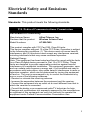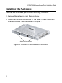
1
Wireless Access Point AT-WA7400 Installation Guide PN 613-000487 RevA Copyright © 2006 Allied Telesyn, Inc. All rights reserved. No part of this publication may be reproduced without prior written permission from Allied Telesyn, Inc. Ethernet is a registered trademark of Xerox Corporation. All other product names, company names, logos or other designations mentioned herein are trademarks or registered trademarks of their respective owners. Allied Telesyn, Inc. reserves the right to make changes in specifications and other information contained in this document without prior written notice. The information provided herein is subject to change without notice. In no event shall Allied Telesyn, Inc. be liable for any incidental, special, indirect, or consequential damages whatsoever, including but not limited to lost profits, arising out of or related to this manual or the information contained herein, even if Allied Telesyn, Inc. has been advised of, known, or should have known, the possibility of such damages. Electrical Safety and Emissions Standards Standards: This product meets the following standards. U.S. Federal Communications Commission Declaration of Conformity Manufacturer Name: Declares that the product: Model Numbers: Allied Telesyn, Inc. Wireless Access Point AT-WA7400 This product complies with FCC Part 15B, Class B Limits: This device complies with part 15 of the FCC Rules. Operation is subject to the following two conditions: (1) This device must not cause harmful interference, and (2) this device must accept any interference received, including interference that may cause undesired operation. Radiated Energy Note: This equipment has been tested and found to comply with the limits for a Class B digital device pursuant to Part 15 of FCC Rules. These limits are designed to provide reasonable protection against harmful interference in a residential installation. This equipment generates, uses and can radiate radio frequency energy and, if not installed and used in accordance with instructions, may cause harmful interference to radio or television reception, which can be determined by turning the equipment off and on. The user is encouraged to try to correct the interference by one or more of the following measures: - Reorient or relocate the receiving antenna. - Increase the separation between the equipment and the receiver. - Connect the equipment into an outlet on a circuit different from that to which the receiver is connected. - Consult the dealer or an experienced radio/TV technician for help. Changes and modifications not expressly approved by the manufacturer or registrant of this equipment can void your authority to operate this equipment under Federal Communications Commission rules. 3 Industry Canada This Class B digital apparatus complies with Canadian ICES-003. Cet appareil numérique de la classe B est conforme à la norme NMB-003 du Canada. Safety and Electromagnetic Emissions Certifications EMI/RFI and Immunity FCC Part 15 Class B; FCC Part 15B, 15C, and 15E Certified; EN 55022/ CISPR 22 Class B; EN 301 893; EN 300 328; EN 301 489 Transmitter EMC; Canada IC; CE Mark emission/ immunity; CE Marked (compliant with RTT&E, EMC, LVD Directives); C-Tick Electrical Safety: UL 60950-1, CSA C22.2 No. 60950-103 (CULUS), EN60950-1 (TUV); TUV, EN 60593-IP53 4 AT-WA7400 Wireless Access Point Installation Guide Translated Safety Statements Important: When you see the , go to the Allied Telesyn website www.alliedtelesyn.com for the translated safety statement in your language. 5 6 Contents Electrical Safety and Emissions Standards .............................3 Safety and Electromagnetic Emissions Certifications ...................4 Translated Safety Statements .......................................................5 Preface .......................................................................................13 Safety Symbols Used in this Guide .............................................14 Where to Find Web-based Guides ..............................................15 Contacting Allied Telesyn ............................................................16 Online Support ....................................................................16 Email and Telephone Support.............................................16 Returning Products..............................................................16 Sales or Corporate Information ...........................................16 Management Software Updates ..........................................16 Chapter 1: Overview .................................................................19 Features ......................................................................................20 Front and Back Panels ................................................................21 LEDs............................................................................................23 Chapter 2: Installation ..............................................................25 Reviewing Safety Precautions.....................................................26 Installation Guidelines .................................................................28 Microwave Ovens ................................................................29 Cordless Telephones ..........................................................29 Other Access Points ............................................................29 Unpacking the Access Point........................................................30 Installing the Antennas ................................................................31 Using the Access Point on a Desktop .........................................33 Mounting an Access Point on a Wall ...........................................34 Mounting the Access Point on a Metal Surface...........................36 Connecting the Access Point to the LAN.....................................37 7 Contents Powering On the Access Point ....................................................38 Running KickStart to Find Access Points on the Network ...........40 Installing KickStart on the Administrator’s PC .....................47 Warranty Registration..................................................................54 Chapter 3: Troubleshooting ....................................................55 Appendix A: Technical Specifications ...................................57 Physical Specifications ................................................................57 Environmental Specifications ......................................................57 Power Specifications ...................................................................57 Safety and Electromagnetic Emissions Certifications .................57 Appendix B: Radio Bands .......................................................59 8 Figures Figure 1: AT-WA7400 Wireless Access Point21 Figure 2: Front and Back Panels22 Figure 3: Location of the Antenna Connectors31 Figure 4: Attaching the Antennas32 Figure 5: Attaching the Rubber Feet33 Figure 6: Aligning the Access Point for Mounting on the Wall35 Figure 7: Attaching the Magnets36 Figure 8: Attaching the LAN Cable37 Figure 9: Connecting the Power Adapter38 Figure 10: PoE Connection39 Figure 11: AT-WA7400 CD Main Page41 Figure 12: KickStart Page42 Figure 13: KickStart Welcome Page43 Figure 14: KickStart Search Results Page44 Figure 15: Administration Dialog Box45 Figure 16: Login Dialog Box46 Figure 17: Basic Settings Page47 Figure 18: KickStart Setup Wizard Dialog Box48 Figure 19: Select Installation Folder Dialog Box49 Figure 20: KickStart Setup Disk Space Dialog box50 Figure 21: KickStart Installation Confirmation Dialog Box51 Figure 22: Installing KickStart Dialog Box52 Figure 23: KickStart Installation Complete Dialog Box53 9 Contents 10 Tables Table 1. Table 2. Table 3. Table 4. Safety Symbols 14 System LEDs 23 LAN LEDs 23 Wireless LEDs 24 11 Tables 12 Preface This guide contains instructions on how to install the AT-WA7400 Wireless Access Point. This preface contains the following sections: “Safety Symbols Used in this Guide” on page 14 “Where to Find Web-based Guides” on page 15 “Contacting Allied Telesyn” on page 16 13 Preface Safety Symbols Used in this Guide This document uses the safety symbols defined in Table 1. Table 1. Safety Symbols Symbol 14 Meaning Description Caution Performing or omitting a specific action may result in equipment damage or loss of data. Warning Performing or omitting a specific action may result in electrical shock. AT-WA7400 Wireless Access Point Installation Guide Where to Find Web-based Guides The installation and user guides for all Allied Telesyn products are available in portable document format (PDF) on our web site at www.alliedtelesyn.com. You can view the documents online or download them onto a local workstation or server. 15 Preface Contacting Allied Telesyn This section provides Allied Telesyn contact information for technical support as well as sales and corporate information. Online Support You can request technical support online by accessing the Allied Telesyn Knowledge Base: http://kb.alliedtelesyn.com. You can use the Knowledge Base to submit questions to our technical support staff and review answers to previously asked questions. Email and Telephone Support For Technical Support via email or telephone, refer to the Support & Services section of the Allied Telesyn web site: www.alliedtelesyn.com. Returning Products Products for return or repair must first be assigned a return materials authorization (RMA) number. A product sent to Allied Telesyn without an RMA number will be returned to the sender at the sender’s expense. To obtain an RMA number, contact Allied Telesyn Technical Support through our web site: www.alliedtelesyn.com. Sales or Corporate Information You can contact Allied Telesyn for sales or corporate information through our web site: www.alliedtelesyn.com. To find the contact information for your country, select Contact Us -> Worldwide Contacts. Management Software Updates New releases of management software for our managed products are available from either of the following Internet sites: 16 AT-WA7400 Wireless Access Point Installation Guide Allied Telesyn web site: www.alliedtelesyn.com Allied Telesyn FTP server: ftp://ftp.alliedtelesyn.com If you prefer to download new software from the Allied Telesyn FTP server from your workstation’s command prompt, you will need FTP client software and you must log in to the server. Enter “anonymous” for the user name and your email address for the password. 17 Preface 18 Chapter 1 Overview The AT-WA7400 Wireless Access Point is a wireless communications hub for devices on your network. It provides continuous, high-speed access between your wireless and Ethernet devices. You administer the AT-WA7400 Wireless Access Point using the AT-WA7400 management software. This chapter contains the following sections: “Features” on page 20 “Front and Back Panels” on page 21 “LEDs” on page 23 19 Chapter 1: Overview Features The features of the AT-WA7400 Wireless Access Point include: High performance 54 Mbps data rate (802.11g - 802.11a with an upgrade as described in Appendix A, “Radio Bands” on page 59.) Security support via 802.11i (WPA2), WPA-PSK, TKIP, AES, IEEE 802.1x, and EAP/802.1 Multiple BSSID and Virtual LAN (VLANs) Inhibit SSID broadcast and Ignore SSID scan MAC Access Control for wireless interface Load balancing 802.11e (WMM only) Wireless Distribution System (WDS) for Wireless Bridge Mode supported AP clustering Rogue AP detection Transmit power control/limiting Power over Ethernet (PoE) capable Two radios and two antennas (to activate the second radio, a firmware upgrade is required) One 10/100 Fast Ethernet port with auto-negotiation, and auto MDI/MDIX, back pressure, and flow control 20 AT-WA7400 Wireless Access Point Installation Guide Front and Back Panels Figure 1 shows the AT-WA7400 Wireless Access Point. 301 Figure 1. AT-WA7400 Wireless Access Point 21 Chapter 1: Overview Figure 2 shows the front and back panels of the wireless access point. System LEDs LAN LEDs Wireless LEDs RESET TO DEFAULT 5V,2.8A LAN Reset Button Power Connector LAN Port Antenna Connectors Figure 2. Front and Back Panels 22 302 AT-WA7400 Wireless Access Point Installation Guide LEDs The system LEDs on the AT-WA7400 Wireless Access Point are described in Table 2. Table 2. System LEDs LED Power Test State Description Off The access point is not receiving power. Green The access point is receiving power. Off No system maintenance in progress. Amber System startup or maintenance in progress. The LAN LEDs are described in Table 3. Table 3. LAN LEDs LED LNK/ACT (100M) LNK/ACT (10 M) 23 State Description On The access point is operating at 100 Mbps. Off The access point is not operating at 100 Mbps. Blinking The access point is sending or receiving data at 100 Mbps. On The access point is operating at 10 Mbps. Chapter 1: Overview Table 3. LAN LEDs (Continued) LED State Description Off The access point is not operating at 10 Mbps. Blinking The access point is sending or receiving data at 10 Mbps. The Wireless LEDs are described in Table 4. Table 4. Wireless LEDs LED LNK/ACT (WLAN a) LNK/ACT (WLAN g) 24 State Description Off No link is detected. Green An 802.11a WLAN link has been made. Blinking Green Network activity is occurring. Off No link is detected. Green An 802.11g WLAN link has been made. Blinking Green Network activity is occurring. Chapter 2 Installation This chapter contains the following sections: “Reviewing Safety Precautions” on page 26 “Installation Guidelines” on page 28 “Unpacking the Access Point” on page 30 “Installing the Antennas” on page 31 “Using the Access Point on a Desktop” on page 33 “Mounting an Access Point on a Wall” on page 34 “Mounting the Access Point on a Metal Surface” on page 36 “Powering On the Access Point” on page 38 “Running KickStart to Find Access Points on the Network” on page 40 “Warranty Registration” on page 54 25 Chapter 2: Installation Reviewing Safety Precautions Please review the following safety precautions before you begin to install the AT-WA7400 Wireless Access Point. Note When you see the , go to the Allied Telesyn web site for translated safety statements. Warning: To prevent electric shock, do not remove the cover. No user-serviceable parts inside. This unit contains hazardous voltages and should only be opened by a trained and qualified technician. To avoid the possibility of electric shock, disconnect electric power to the product before connecting or disconnecting the LAN cables. 3 Warning: Do not work on equipment or cables during periods of lightning activity.4 Warning: Power cord is used as a disconnection device. To de-energize equipment, disconnect the power cord. 5 Pluggable Equipment. The socket outlet shall be installed near the equipment and shall be easily accessible. 7 26 AT-WA7400 Wireless Access Point Installation Guide Warning: Operating Temperature. This product is designed for a maximum ambient temperature of 40° degrees C. 9 All Countries: Install product in accordance with local and National Electrical Codes. 10 Caution: Do not install in direct sunlight, or a damp or dusty place. 18 27 Chapter 2: Installation Installation Guidelines Allied Telesyn recommends that you have an Allied Telesyncertified RF specialist conduct a site survey to determine the ideal locations for all your Allied Telesyn wireless network devices. To conduct a proper site survey, you need to have special equipment and training. The following general practices should be followed in any installation: Locate access points centrally within areas requiring coverage. Overlap access point radio coverage areas to avoid coverage holes. Position the access point so that its LEDs are visible. The LEDs are useful for troubleshooting. Install wired LAN cabling within node limit and cable length limitations. Use an uninterruptible power supply (UPS) when AC power is not reliable. Proper antenna placement can help improve range. For information about antenna options, contact your local Allied Telesyn representative. When determining ideal locations for the access points, be aware that you may see network performance degradation from microwave ovens, cordless telephones, and other access points. For more information, see the next sections. Note Microwave ovens, cordless telephones, and other access points do not degrade the network performance of the 802.11a radio. 28 AT-WA7400 Wireless Access Point Installation Guide Microwave Ovens Microwave ovens operate in the same frequency band as 802.11g and 802.11b radios; therefore, if you use a microwave oven within range of your wireless network, you may notice network performance degradation. Both your microwave oven and your wireless network will continue to function, but you may want to consider relocating your microwave oven out of range of your access point. Cordless Telephones If you have an 802.11g or 802.11b radio in your access point, the radio may experience interference from some cordless telephones. For optimal performance, consider operating cordless telephones out of range of your access points. Other Access Points Access points that are configured for the same frequency and that are in the same radio coverage area may interfere with each other and decrease throughput. You can reduce the chance of interference by configuring access points at least five channels apart, such as channels 1, 6, and 11. 29 Chapter 2: Installation Unpacking the Access Point To unpack the AT-WA7400 Wireless Access Point, perform the following procedure: 1. Remove all components from the shipping package. Note Store the packing material in a safe location. You must use the original shipping material if you need to return the unit to Allied Telesyn. 2. Place the access point on a secure, level surface. 3. Ensure that the following hardware components are included in your access point package. If any item is missing or damaged, contact your Allied Telesyn sales representative for assistance. One AT-WA7400 Wireless Access Point Two antennas One wall mount kit containing two wall anchors and two screws One AC adapter One RJ45 management cable Four rubber feet One magnet kit containing four magnets and four screws One documentation CD with KickStart utility This installation guide Warranty card 30 AT-WA7400 Wireless Access Point Installation Guide Installing the Antennas To install the antennas, perform the following procedure: 1. Remove the antennas from their package. 2. Locate the antenna connectors in the back of the AT-WA7400 Wireless Access Point, as shown in Figure 3. 5V,2 .8A RES ET TO DEF AUL T 303 LAN Antenna Connectors Figure 3. Location of the Antenna Connectors 31 Chapter 2: Installation 3. Screw one antenna into each antenna connector, as shown in Figure 4. 5V,2 .8A RES ET TO DEF AUL T 304 LAN Figure 4. Attaching the Antennas You can point the antennas in the direction that provides the best signal strength. 32 AT-WA7400 Wireless Access Point Installation Guide Using the Access Point on a Desktop You can place the AT-WA7400 Wireless Access Point on a desktop or other flat surface. To place the AT-WA7400 Wireless Access Point on a desktop, perform the following procedure: 1. Turn the access point over so that the top is resting on a flat surface. 2. Attach the four rubber feet to the bottom of the access point as shown in Figure 5. LAN 305 5V,2 .8A RES ET TO DEF AUL T Figure 5. Attaching the Rubber Feet 3. Turn the access point over and place it on a flat, secure surface such as a desk or table, leaving ample space around the unit for ventilation. 33 Chapter 2: Installation Mounting an Access Point on a Wall To mount the AT-WA7400 Wireless Access Point on a wall, perform the following procedure: 1. Select a wall location and mark two hole locations for the anchors 98.425 mm (3.875 in.) apart. 2. At the two marked hole locations, pre-drill for the drywall anchors. 3. Install the anchors and drive the screws into the anchors leaving approximately 4.76 mm (.1875 in.) exposed. 34 AT-WA7400 Wireless Access Point Installation Guide 5V ,2 .8 A R ES ET TO D EF AU LT LA N 4. Align the keyholes on the back with the screw heads, as shown in Figure 6. 307 Figure 6. Aligning the Access Point for Mounting on the Wall 5. Place the keyhole slots on the bottom of the access point over the screw heads. 6. Slide the access point down onto the screw heads so that the access point is securely mounted on the wall. You can install the access point either horizontally or vertically. 35 Chapter 2: Installation Mounting the Access Point on a Metal Surface To mount the AT-WA7400 Wireless Access Point on a metal surface, perform the following procedure: 1. Select a location for the access point. 2. Turn the access point over and place it on a secure surface. 3. Screw the four magnets into the back of the access point, as shown in Figure 7. LAN 5V,2 .8A RES ET TO DEF AUL T Figure 7. Attaching the Magnets 4. Mount the access point on a metal surface. 36 306 AT-WA7400 Wireless Access Point Installation Guide Connecting the Access Point to the LAN To connect the AT-WA7400 Wireless Access Point to the LAN, perform the following procedure: 1. Locate the RJ45 cable in the box. 2. Connect one end of the cable to the LAN. 3. Connect the other end of the cable to the LAN port on the back of the access point, as shown in Figure 8. 5V,2 .8A RES ET TO DEF AUL T 308 LAN Figure 8. Attaching the LAN Cable 37 Chapter 2: Installation Powering On the Access Point To power on the access point, perform the following procedure: Warning: Do not work on equipment or cables during periods of lightning activity.4 Warning: Power cord is used as a disconnection device. To de-energize equipment, disconnect the power cord. 5 1. Do one of the following: a. Plug the power cord on the adapter into the power connector on the back panel, as shown in Figure 9, and plug the power adapter into a wall outlet. 5V,2 .8A RES ET TO DEF AUL T 309 LAN Figure 9. Connecting the Power Adapter 38 AT-WA7400 Wireless Access Point Installation Guide b. Plug a LAN cable from a unit that supports PoE into the LAN port, as shown in Figure 10. No other power connection is required. 5V,2 .8A RES ET TO DEF AUL T 308 LAN Figure 10. PoE Connection 2. Verify that the POWER LED is green. If the LED is off, refer to Chapter 3, ”Troubleshooting” on page 55. The access point is now powered on and ready for network operation. 39 Chapter 2: Installation Running KickStart to Find Access Points on the Network KickStart is an easy-to-use utility for discovering and identifying new AT-WA7400 Wireless Access Points. KickStart scans the network looking for access points, displays ID details on those it finds, and provides access to the AT-WA7400 Management Software. Note KickStart (and the other AT-WA7400 tools) recognizes and configures only AT-WA7400 Wireless Access Points. KickStart does not find or configure non-AT-WA7400 Wireless Access Points and will not find any other devices. Note Run KickStart only in the subnet of the internal network (SSID). Note KickStart finds only those access points that have IP addresses. IP addresses are dynamically assigned to access points if you have a DHCP server running on the network. If you deploy the access point on a network with no DHCP server, the default static IP address (192.168.1.230) is used. Caution Use caution with non-DHCP enabled networks: Do not deploy more than one new access point on a non-DHCP network because they will use the same default static IP addresses and conflict with each other. 40 AT-WA7400 Wireless Access Point Installation Guide To start the discovery process, perform the following procedure: 1. Do one of the following to create an Ethernet connection between the access point and your computer: Connect one end of an Ethernet cable to the LAN port on the access point and the other end to the same hub where your PC is connected. Connect one end of an Ethernet cable to the LAN port on the access point and the other end of the cable to the Ethernet port on the your PC. 2. Insert the AT-WA7400 Wireless Access Point CD into the CDROM drive on your computer. The CD’s main page is shown in Figure 11. Figure 11. AT-WA7400 CD Main Page 3. Click KickStart Utility. 41 Chapter 2: Installation The KickStart page, as shown in Figure 12, provides two options: Open KickStart and Install KickStart. Figure 12. KickStart Page For information about installing KickStart, refer to “Installing KickStart on the Administrator’s PC” on page 47. Otherwise, continue with this procedure. 4. Click Open KickStart. 42 AT-WA7400 Wireless Access Point Installation Guide The KickStart Welcome page is displayed, as shown in Figure 13. Figure 13. KickStart Welcome Page 5. Click Next to search for access points. 43 Chapter 2: Installation Wait for the search to complete, or until KickStart has found your new access points, as shown in Figure 14. Figure 14. KickStart Search Results Page Note The KickStart utility only finds other AT-WA7400 Wireless Access Points. If KickStart does not find the AT-WA7400 Wireless Access Point you just installed, an informational window is displayed with troubleshooting information about your LAN and power connections. 6. Review the list of access points that KickStart found, as shown in the example in Figure 14. The access points are listed with their locations, media access control (MAC) addresses, and IP addresses. If you are installing the first access point on a single-access-point network, only one entry is displayed on this page. 44 AT-WA7400 Wireless Access Point Installation Guide 7. Verify the MAC addresses against the hardware labels for each access point. This will be especially helpful later in providing or modifying the descriptive Location name for each access point. 8. Click Next. The Administration dialog box opens, as shown in Figure 15. Figure 15. Administration Dialog Box Note KickStart provides a link to the AT-WA7400 management software web pages via the IP address of the first access point of each model. The AT-WA7400 management software is a centralized management tool that you can access through the IP address for any access point in a cluster. 45 Chapter 2: Installation After your other access points are configured, you can also link to the AT-WA7400 management software web pages using the IP address for any of the other AT-WA7400 Wireless Access Points, for example http://IPAddressOfAccessPoint. 9. Click Administration. You are prompted for a user name and password, as shown in Figure 16. Figure 16. Login Dialog Box The default user name is “manager” and the default password is “friend.” 10.Enter the user name and password and click OK. 46 AT-WA7400 Wireless Access Point Installation Guide The Basic Settings page opens, as shown in Figure 17. Figure 17. Basic Settings Page Refer to the AT-WA7400 Management Software User’s Guide for information about how to configure the basic settings. Installing KickStart on the Administrator’s PC To install the KickStart utility on the administrator’s PC, perform the following procedure: 1. Insert the AT-WA7400 Wireless Access Point CD into the CDROM drive on your computer. The CD’s main page is shown in Figure 11 on page 41. 47 Chapter 2: Installation 2. Click KickStart Utility. The KickStart page, as shown in Figure 12 on page 42, provides two options: Open KickStart and Install KickStart. The Open KickStart option is described in “Running KickStart to Find Access Points on the Network” on page 40. 3. Click Install KickStart. The KickStart Setup Wizard dialog box is shown in Figure 18. Figure 18. KickStart Setup Wizard Dialog Box 4. Click Next. 48 AT-WA7400 Wireless Access Point Installation Guide The Select Installation Folder dialog box is shown in Figure 19. Figure 19. Select Installation Folder Dialog Box 5. Do one of the following: To see how much disk space the files require, click Disk Cost. 49 Chapter 2: Installation The KickStart Setup Disk Space dialog box is shown in Figure 20. Figure 20. KickStart Setup Disk Space Dialog box Select the drive where you want to install KickStart, and then click OK. Click Browse to select a specific location for the KickStart utility. The Browse for Folder window shows the default folder where the utility will be installed unless you select a different location. If this selection is OK, click OK. Otherwise, select a different folder and click OK. 6. Click Next. 50 AT-WA7400 Wireless Access Point Installation Guide The KickStart Setup confirmation dialog box is shown in Figure 21. Figure 21. KickStart Installation Confirmation Dialog Box 7. Click Next to start the installation. 51 Chapter 2: Installation The Installing KickStart dialog box is shown in Figure 22. Figure 22. Installing KickStart Dialog Box 52 AT-WA7400 Wireless Access Point Installation Guide When the installation is complete, the Installation Complete dialog box is displayed, as shown in Figure 23. Figure 23. KickStart Installation Complete Dialog Box 8. Click Close. You can now run KickStart from the Programs folder under Allied Telesyn. 53 Chapter 2: Installation Warranty Registration After installing your access point, you can register your product by completing the enclosed warranty card and sending it to Allied Telesyn. 54 Chapter 3 Troubleshooting If the AT-WA7400 Wireless Access Point is not operating correctly, do one of the following: Press the Reset to Default button once to reboot the access point. You can also reset the access point through the AT-S77 management software. See Chapter 20, “Maintenance and Monitoring” in the AT-WA7400 Management Software User’s Guide. Hold in the Reset to Default button for more than five seconds to restore the factory default settings. You can also restore the factory default settings through the AT-S77 management software. See Chapter 20, “Maintenance and Monitoring” in the AT-WA7400 Management Software User’s Guide. 55 Chapter 3: Troubleshooting 56 Appendix A Technical Specifications Physical Specifications Dimensions: 176.34 mm x 103.62 mm x 23.20 mm (W x D x H) (6.94 in. x 4.07 in. x .91 in.) Weight: 250 g (8.81 oz.) Environmental Specifications Operating Temperature: 0 to 50°C Storage Temperature: -20 to 70°C Operating Humidity: 10 to 90% noncondensing Storage Humidity: 10 to 95% noncondensing Operating Altitude Range: 3,000 m Power Specifications Input Supply Voltage: Power over Ethernet or 5 VDC/2.8 A DC adapter Power Consumption: 5.75 W (max.) Safety and Electromagnetic Emissions Certifications EMI/RFI and Immunity FCC Part 15 Class B; FCC Part 15B, 15C, and 15E Certified; EN 55022/ CISPR 22 Class B ; EN 301 893; EN 57 Appendix A: Technical Specifications 300 328; EN 301 489 Transmitter EMC; Canada IC; CE Mark emission/ immunity; CE Marked (compliant with RTT&E, EMC, LVD Directives); C-Tick Electrical Safety: 58 UL 60950-1, CSA C22.2 No. 60950-103 (CULUS), EN60950-1 (TUV); TUV, EN 60593-IP53 Appendix B Radio Bands Allied Telesyn’s AT-WA7400 Wireless Access Point is capable of operating in the 2.4GHZ (IEEE 802.11g/b) AND in the 5GHZ band (IEEE 802.11a) simultaneously. The access point is shipped with the 802.11g/b radio enabled and is software upgradeable to operate in 802.11g/b and 802.11a. For further information about this upgrade, please contact your Allied Telesyn sales representative. Some of the advantages of the 802.11a option are: Higher performance. 802.11a can deliver data rates up to 54Mbps and there is enough room in the 5GHz spectrum to support up to 12 access points operating in the same area without causing interference between access points. This equates to 432Mbps (12 X 54Mbps) total data rate performance. With 802.11g, you have three non-overlapping channels for setting access point frequencies, which can limit capacity. Less RF interference: The growing use of 2.4GHz cordless phones and Bluetooth devices is crowding the radio spectrum within many facilities. This significantly decreases the performance of 802.11g wireless LANs. The use of 802.11a operating in the relatively un-crowded 5GHz band avoids this interference. Ability to use the Wireless Distribution System (WDS) feature utilizing the 802.11a radio for bridging to another access point while servicing 802.11g customers without using user bandwidth for the bridging function. 59 Appendix B: Radio Bands 60