1
5110XM
Control / Communicator
Installation and Setup Guide
N8026V2 3/10 Rev B
ii
UL864 Compliance Requirements
General Information
The 5110XM provides features that allow the system to comply with UL864 installation requirements. The following features must be set accordingly in order for the system to comply with UL864
installation requirements:
The reporting of bypassed points to the central station must be enabled
Fire alarm notification circuits must be supervised
Fire installations require the use of a synchronization module to synchronize the sounders
and strobes on the system
Supervision must be enabled for both the main and backup phone lines
The delay water flow points must not exceed 90 seconds
The test report interval must be set for a maximum of 24 hours
Non-Compliant UL864 Features
The following features are not UL864 compliant and may not be used in a UL864 installation:
Ring Detection Count must be set to 0 (disabled)
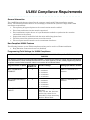
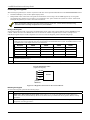
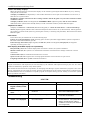
Programming Field Settings for UL864 Compliance
NOTICE TO USERS, INSTALLERS, AUTHORITIES HAVING JURISDICTION, AND OTHER INVOLVED
PARTIES
This product incorporates field-programmable software. In order for the product to comply with the requirements
in the Standard for Control Units and Accessories for Fire Alarm Systems, UL 864, certain programming features
or options must be limited to specific values or not used at all as indicated below.
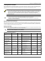
Program feature or option
Permitted in
UL864? Y/N
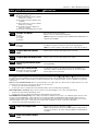
30 ALARM BELL
TIMEOUT
Y
31 AUXILIARY RELAY
TIMEOUT
Y
95 RING DETECTION
COUNT
Y
Possible settings
Settings permitted in UL 864
0 = no timeout
1 = 4 minutes
2 = 8 minutes
3 = 12 minutes
4 = 16 minutes.
0 = no timeout
1 = 4 minutes
2 = 8 minutes
3 = 12 minutes
4 = 16 minutes.
Enter 0 to disable ring
detection.
Enter 1-9, #10, #11, #12, #13,
#14 for ring counts of 1-14.
Enter #15 to select Answering
Machine Defeat Mode
Must be a minimum of 6
minutes.
Must be a minimum of 6
minutes.
Must be set to “0” (disable).
iii
5110XM Installation and Setup Guide
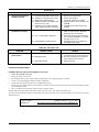
Table of Contents
UL864 Compliance Requirements.......................................................................................................iii
General Information ............................................................................................................................................ iii
Non-Compliant UL864 Features ......................................................................................................................... iii
Programming Field Settings for UL864 Compliance........................................................................................... iii
List of Figures .........................................................................................................................................v
Conventions Used in This Manual ................................................................................................. vi
SECTION 1..........................................................................................................................................1-1
General Description.............................................................................................................................1-1
About the 5110XM ........................................................................................................................................... 1-1
Features ........................................................................................................................................................... 1-1
SECTION 2..........................................................................................................................................2-1
Installing the Control ...........................................................................................................................2-1
Mounting the Control Cabinet .......................................................................................................................... 2-1
Installing the Cabinet Lock ............................................................................................................................... 2-1
Installing the Control's Circuit Board ................................................................................................................ 2-1
Commercial Fire Installation Guidelines .......................................................................................................... 2-3
Installing the Keypads ...................................................................................................................................... 2-4
Installing External Sounders ............................................................................................................................ 2-5
Auxiliary Relay Connections ............................................................................................................................ 2-7
Telephone Line Connections ........................................................................................................................... 2-8
Wiring Devices to Zones 1-5 ............................................................................................................................ 2-9
Determining the Control’s Power Supply Load .............................................................................................. 2-12
Determining the Size of the Standby Battery ................................................................................................. 2-13
SECTION 3..........................................................................................................................................3-1
Programming .......................................................................................................................................3-1
Entering and Exiting Programming Mode ........................................................................................................ 3-1
Data Field Programming Mode ........................................................................................................................ 3-1
Menu Mode Programming................................................................................................................................ 3-2
Zone Number Designations ............................................................................................................................. 3-2
Zone Response Type Definitions..................................................................................................................... 3-2
SECTION 4..........................................................................................................................................4-1
Data Field Descriptions .......................................................................................................................4-1
About Data Field Programming........................................................................................................................ 4-1
Programming Data Fields ................................................................................................................................ 4-1
SECTION 5..........................................................................................................................................5-1
Menu Mode Programming...................................................................................................................5-1
General Information ......................................................................................................................................... 5-1
Field 56 Zone Programming ......................................................................................................................... 5-1
Field 82 Zone Programming ......................................................................................................................... 5-2
Adding Custom Words ..................................................................................................................................... 5-4
Alpha Vocabulary List ...................................................................................................................................... 5-5
Character (ASCII) Chart................................................................................................................................... 5-5
SECTION 6..........................................................................................................................................6-1
System Communication ......................................................................................................................6-1
General Information ......................................................................................................................................... 6-1
Report Code Formats....................................................................................................................................... 6-1
iv
Table of Contact ID Event Codes .................................................................................................................... 6-1
SECTION 7..........................................................................................................................................7-1
Downloading Primer ............................................................................................................................7-1
General Information ......................................................................................................................................... 7-1
Getting On-Line with a Control Panel .............................................................................................................. 7-2
SECTION 8..........................................................................................................................................8-1
System Operation ................................................................................................................................8-1
User Codes ...................................................................................................................................................... 8-1
Keypad Functions ............................................................................................................................................ 8-2
SECTION 9..........................................................................................................................................9-1
Testing the System ..............................................................................................................................9-1
Fire Walk Test .................................................................................................................................................. 9-1
Dialer Test ........................................................................................................................................................ 9-1
Trouble Conditions ........................................................................................................................................... 9-1
Troubleshooting ............................................................................................................................................... 9-2
APPENDIX A ..................................................................................................................................... A-1
Regulatory Agency Statements......................................................................................................... A-1
APPENDIX B .....................................................................................................................................B-1
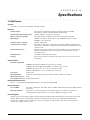
Specifications .....................................................................................................................................B-1
5110XM Control ............................................................................................................................................... B-1
Index ............................................................................................................................................ Index-1
The Limitations of This Alarm System............................................................................ Follows Index
List of Figures
Figure 2-1: Installing the Lock ................................................................................................................................ 2-1
Figure 2-2: Circuit Board Mounting Details............................................................................................................. 2-2
Figure 2-3: Circuit Board Installation ...................................................................................................................... 2-3
Figure 2-4: Keypad Connections to the Control Board........................................................................................... 2-4
Figure 2-5: External Sounder Connections ............................................................................................................ 2-7
Figure 2-6: Wiring the Auxiliary Relay Output For Unsupervised Alarm Output. .................................................. 2-8
Figure 2-7: Wiring the Auxiliary Relay Output For 4-Wire Smoke Detector Power Usage. ................................... 2-8
Figure 2-8: 4-Wire Smoke Detector Connections................................................................................................. 2-11
Figure 2-9: 2-Wire Smoke Detector Connected to Zone 5 ................................................................................... 2-11
Figure 2-10: Connecting the Backup Batteries..................................................................................................... 2-14
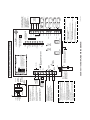
5110XM Simplified Wiring Diagram...............................................................................................Inside Back Cover
v
5110XM Installation and Setup Guide
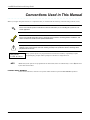
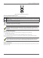
Conventions Used in This Manual
Before you begin using this manual, it is important that you understand the meaning of the following symbols (icons).
UL
These notes include specific information that must be followed if you are installing this system for a UL
Listed application.
These notes include information that you should be aware of before continuing with the installation, and
that, if not observed, could result in operational difficulties.
This symbol indicates a critical note that could seriously affect the operation of the system, or could cause
damage to the system. Please read each warning carefully. This symbol also denotes warnings about
physical harm to the user.
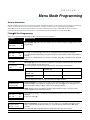
ZONE PROG?
1 = YES 0 = NO 0
00
Many system options are programmed in an interactive mode by responding to alpha
keypad display prompts. These prompts are shown in a single-line box.
Additional system options are programmed via data fields, which are indicated by a “star” () followed
by the data field number.
PRODUCT MODEL NUMBERS:
Unless noted otherwise, references to specific model numbers represent HONEYWELL products.
vi
S E C T I O N
1
General Description
About the 5110XM
The 5110XM is a fire alarm control/communicator that supports 5 style B (for further explanation of style B, refer to
NFPA 72 National Fire Alarm Code Chapter 3: Protected Premises Fire Alarm Systems) hardwired zones. It may be
used as a slave Digital Alarm Communicator Transmitter (DACT) providing central station or remote station service for
a listed Fire Alarm Control Panel (FACP). It may also be used as a stand-alone non-coded local, central station or
remote station control.
Features
Hardwire Zones
Provides 5 style B hardwire zones
Supports up to 16 2-wire smoke detectors each on zone 5
Provides 300 – 500ms response time
Supports 4-wire smoke detectors on any zone (power to these should be supplied from the control's auxiliary relay
power output)
Remote Keypads
The following keypads may be used:
Fixed-Word Keypads: 6150
Alpha Keypad: 6160
When used as a DACT only, a keypad is not required, but may be used to provide supplementary status
annunciation.
UL
When used as a control, optional keypads may be used in conjunction with the control panel's LED indicators
and SILENCE/RESET button. If used, one optional keypad must be mounted within 3 feet of the control with the
wiring run in conduit.
User Codes (for use with remote keypads)
1 Installer code for entire system (user 1– intended for use by installer)
5 Secondary user codes (users 2–6; user 2 intended for use by principle end user)
Backup Dialer
Has built-in backup dialer for connecting to a second supervised telephone line.
Bell Output
Provides one 12VDC (nominal), 1A output, which may be configured for Style Y (for further explanation of style Y, refer
to NFPA 72 National Fire Alarm Code Chapter 3: Protected Premises Fire Alarm Systems), EOLR supervision (for use
with polarized alarm sounding devices) or for no supervision (no EOLR used).
Auxiliary Relay
Provides a built-in 12V wet or dry (jumper selectable) "Form C" relay which can be used for one of the following:
Alarm activation on selected zones, silenced by User Code + [OFF]
Trouble/Supervisory activation
4-wire smoke detector reset
Battery saving feature (disconnects power from non-critical loads 4 hours after AC power loss)
Alarm activation on selected zones, silenced by Code + [#] + [67] (can be used for elevator recall)
1-1
5110XM Installation and Setup Guide
Built-in Indicators and Switches
A built-in warning sounder (Piezo) that provides alarm, supervisory, and trouble sounds
10 LED indicators provide visual status of (1) AC Power, (2) Battery Trouble, (3) Communication Failure, (4) Telco
Line Fault, (5) Silenced Audible Conditions, (6) Supervisory, (7) Alarm, (8) Trouble, (9) Main Dialer Line Seize, and
(10) Backup Dialer Line Seize
A Silence/Reset push-button allows audible warnings to be silenced and smoke detectors to be reset
Programming
Programmed options are stored in electrically erasable, non-volatile EEROM memory (information can be reprogrammed
at any time and will not be lost in the event of a power loss). The system can be programmed by one of the following
methods:
On-site using an alpha keypad
From a remote location via an IBM compatible computer using the Compass Downloading software
UL
Remote programming may only be used when a service technician is at the site during downloading
Communication Formats Supported
ADEMCO Low Speed (Standard or Expanded)
Sescoa/Radionics (Standard or Expanded)
ADEMCO Express
ADEMCO Contact ID
AC Power Input
Uses an enclosed, permanently-wired, 120VAC transformer rated @ 18VAC, 40VA (supplied) with manually resettable
circuit breaker.
Auxiliary Power Output
Provides 12VDC, 350mA maximum for peripherals such as keypads.
Uses Positive Temperature Coefficient Thermistors (PTCs) for protection. There are no replaceable fuses.
Back-Up Battery
Uses a rechargeable 12VDC, 7AH/14AH maximum lead acid (gel cell) battery for back-up power (dual battery cable
supplied)
1-2
S E C T I O N
2
Installing the Control
This section describes the procedures for mounting and wiring the control panel and all the peripheral devices.
Mounting the Control Cabinet
To mount the control cabinet, perform the following steps:
Step
Action
1
Before mounting the circuit board, remove the metal knockouts for the wiring entry that you will be using.
DO NOT ATTEMPT TO REMOVE THE KNOCKOUTS AFTER THE CIRCUIT BOARD HAS BEEN
INSTALLED.
2
Using fasteners or anchors (not supplied), mount the control cabinet to a sturdy wall in a clean, dry area
that is not readily accessible to the general public. The back of the cabinet has 4 holes for this purpose.
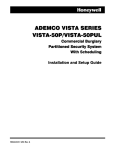
Installing the Cabinet Lock
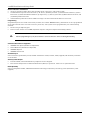
To install the lock, perform the following steps:
Step
Action
1
Remove the cabinet door, and the lock knockout from the door. Insert the key into the lock.
2
Position the lock in the hole, making certain that the latch will make contact with the latch bracket when
the door is closed.
3
When correctly positioned, push the lock until it is held securely by its snap tabs.
Use the supplied lock (Honeywell No. K4445).
CHECK
POSITION
LOCKED
PUSH
ON LOCK
UNTIL IT
IS SEATED
SECURELY
SNAP
TAB
CABINET DOOR
BOTTOM
SNAP
TAB
STEP 1
STEP 2
cab_lock_snap-001-V0
UNLOCKED
ADEMCO
ADEMCO
PUSH
Figure 2-1: Installing the Lock
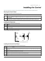
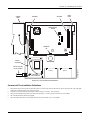
Installing the Control's Circuit Board
To install the circuit board in the cabinet, perform the following steps:
Step
Action
1
If an optional rear tamper switch is going to be used, remove the 4 screws securing the back plate to
the cabinet, then remove the knockout from the back plate. Install the rear tamper switch, then replace the
back plate.
2
Ensure the back plate mounting screws (4) are tight.
3
Install the 3 lower Standoffs with their screws and lock washers along the bottom of the back plate. Refer to
Figure 2-2. Leave the screws loose to allow the circuit board to slip in.
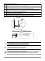
4
Install the 2 upper Standoffs on the back plate. Refer to Figure 2-3 for their location.
2-1
5110XM Installation and Setup Guide
5
Slip the bottom part of the circuit board onto the 3 lower Standoffs ensuring it is under the lock washers.
Then snap the top part of the circuit board onto the 2 upper Standoffs.
6
Tighten the 3 screws securing the circuit board to the 3 lower Standoffs.
7
Install the LED Indicator board and connect its cable to J5 on the printed circuit board.
8
ENSURE FACILITY POWER IS OFF.
Remove the Power Supply's cover plate (4 screws). Refer to Figure 2-3 and the Simplified Wiring Diagram
(inside of back cover) and install the earth ground connections.
9
Use wire nuts (not supplied) to connect the facility power wiring to the power supply transformer's black and
white wires. Replace the power supply cover plate.
10
Connect the transformer's 18VAC BLUE flying leads which emerge from the top of the enclosure to the
circuit board's AC terminals (Terminals 1 and 2). Replace the power supply cover plate.
Back Plate
Circuit
Board
Lock
Washer
Standoffs
Screw
Remove Knockout
if using a rear
Tamper Switch
5110XM-005-V1
Standoffs(3)
Figure 2-2: Circuit Board Mounting Details
The control panel requires connection to a good earth ground in order to provide proper 120VAC shock hazard
protection, lightening transient protection, and earth ground fault detection.
UL
2-2
Refer to the National Electrical Code for proper earth grounding methods.
A dedicated 120VAC circuit must be used for fire applications.
Wires must be rated for 90 degrees C or higher operation.
Make sure that the dedicated AC circuit is not powered at this time.
Apply AC power only after all other wiring, except the backup battery wiring, has been completed.
Section 2 – Installing the Control
Cabinet
Door
Back
Plate
Standoff
Standoff
LED Indicator
Board
J5
Standoffs
(3)
Wires must be
run in Conduit
+
Battery
Wired to
Transformer
+
Battery
5110XM-004-V1
Facility
Ground
Figure 2-3: Circuit Board Installation
Commercial Fire Installation Guidelines
Dress field wiring away from the microprocessor (center) section of the PC board. Dress wiring to the left and right
sides of the cabinet and secure using tie wraps.
Separate all power-limited wiring from other wiring by at least ¼-inch (6.4mm).
Non-power-limited wiring that exits the control panel (i.e., facility power) must be run in conduit.
All unused knockouts must be plugged.
All wiring that exits the control panel must be strain-relieved (e.g., tie-wrapped).
2-3
5110XM Installation and Setup Guide
Installing the Keypads
The following keypads may be used in conjunction with the control panel's LED indicators and SILENCE/RESET button:
Fixed-Word Display: 6150, and/or Alpha Display: 6160
Independent of the restrictions on keypads for stand-alone control usage, the 5110XM supports up to 4 keypads
provided that the 350mA current rating is not exceeded for aux. power and for the system as a whole. Fixed word
and alpha keypads may be used in the same installation.
Many municipalities require that fire alarm annunciators be red in color. Check with the authority having
jurisdiction before choosing a keypad color for your installation.
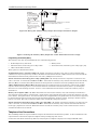
Wiring to the Keypads
If optional keypads are used, one must be mounted within 3 feet of the control panel with the wiring (#22AWG) run in
conduit. When used as a slave DACT, there are no restrictions. Remote keypads may be wired to a single run or
individual keypads may be wired to separate wire runs. To wire the keypads, perform the following steps:
Step
1
Action
Use the table below to determine the length of any single wire run based on the total loading on that run. The
length of all wire runs combined must not exceed 900 feet if unshielded cable is used. If shielded cable is used,
the combined wire run length must not exceed 450 feet.
Wire Size
100mA
200mA
300mA
350mA
#22
200’
125’
80’
71’
#20
400’
200’
130’
110’
#18
625’
310’
200’
170’
#16
900’
450’
300’
250’
2
Run field wiring from the control to the keypads (using standard 4-conductor twisted wire cable using the wire
gauge determined in step 1).
3
Connect the wires to terminals 17, 18, 19 and 20 on the control panel (see Figure 2-4).
KEYPAD CONNECTOR CABLE
(supplied with keypads)
20
19
18
YELLOW
GREEN
BLACK
KEYPAD
RED
17
Control
Terminals
Figure 2-4: Keypad Connections to the Control Board
Mounting the Keypads
To mount the keypads, perform the following steps:
Step
Action
1
Make sure addressable type keypads (6150, 6160) are set to the non-addressable mode (address 31),
which is the factory default setting. Refer to the instructions provided with the keypad for address setting
procedure.
2
Mount the keypads at a height that is convenient for the user. Refer to the instructions provided with the
keypad for mounting procedure.
2-4
Section 2 – Installing the Control
Installing External Sounders
The 5110XM provides one notification appliance circuit output rated 12VDC nominal (10-14VDC), 1A maximum, which
may be connected to 12V alarm indicating devices (horns, bells, sirens, etc.). This output may be configured for Style Y
EOLR supervision or no supervision and is intended for use as a supervised fire alarm indicating circuit.
The bell output must be used for fire alarm annunciation when the 5110XM is used as a stand alone local
control. Unless otherwise specified by the local AHJ, use of the bell output is not required for all other DACT and
stand alone control installations. When used, the bell should be configured for supervision. 24 hour non-fire
alarms (ex. type 07) must be programmed to activate the auxiliary relay output and not the bell output.
The total alarm current that can be drawn from the bell, auxiliary relay, and auxiliary power outputs combined
must not exceed 1A.
UL
Commercial fire alarm systems require Notification Appliance Circuit to be supervised.
This control complies with National Fire Protection Association (NFPA) requirements for temporal pulse
sounding of fire notification appliances.
Notification Appliance Circuit Supervision
When supervision is enabled, the 5110XM monitors the Notification Appliance Circuit wiring for open and short circuit
faults while the output is inactive. The system provides a trouble indication on Zone 6 (Zone 6 must be programmed for
a 24-hour response type) when an open occurs; or when a short occurs between the Bell (+) and Bell (-) terminal wiring,
or between the Bell (+) terminal wiring and earth ground.
Wiring the Alarm Output
The wiring of the Notification Appliance Circuit depends upon whether you are going to supervise the circuit
or not. Use the appropriate procedure below for your application.
UL
Use only UL Listed sounding devices for UL installations.
Compatible Alarm Indicating Devices
SOUNDER TYPE
MANUFACTURER
MODEL #
SOUNDER TYPE
MANUFACTURER
MODEL #
UL listed Grade A Bell in
Housing
Honeywell/ ADEMCO
AB12M-ADT
4-Wire Ceiling Mount Horn/Strobe,
12/24V, Standard Candela, Red,
Outdoor
SYSTEM SENSOR
PC4RK
RX7 UL Indoor Sounder, 12V
ADT
875936B
4-Wire Ceiling Mount Horn/Strobe,
12/24V, High Candela, Red, Outdoor
SYSTEM SENSOR
PC4RHK
Chime, 12/24V, Selectable
Tone & Volume, Red
SYSTEM SENSOR
CHR
4-Wire Ceiling Mount Horn/Strobe,
12/24V, Standard Candela, White
SYSTEM SENSOR
PC4W
Chime, 12/24V, Selectable
Tone & Volume, White
SYSTEM SENSOR
CHW
4-Wire Ceiling Mount Horn/Strobe,
12/24V, High Candela, White
SYSTEM SENSOR
PC4WH
Chime/Strobe, 12/24V,
Selectable Candela, Tone &
Volume, Red
SYSTEM SENSOR
CHSR
2-Wire Wall Mount Strobe, 12/24V,
Standard Candela, Red
SYSTEM SENSOR
SR
Chime/Strobe, 12/24V,
Selectable Candela, Tone &
Volume, White
SYSTEM SENSOR
CHSW
2-Wire Wall Mount Strobe, 12/24V,
High Candela, Red
SYSTEM SENSOR
SRH
Horn, 12/24V, Red
SYSTEM SENSOR
HR
Wall Mount Strobe, 12/24V, Standard
Candela, Red, Outdoor
SYSTEM SENSOR
SRK
Horn, 12/24V, White
SYSTEM SENSOR
HW
Wall Mount Strobe, 12/24V, High
Candela, Red, Outdoor
SYSTEM SENSOR
SRHK
Horn, 12/24V, Outdoor, Red
SYSTEM SENSOR
HRK
Wall Mount Strobe, 12/24V, Standard
Candela, White
SYSTEM SENSOR
SW
2-Wire Wall Mount
Horn/Strobe, 12/24V,
Standard Candela, Red
SYSTEM SENSOR
P2R
Wall Mount Strobe, 12/24V, High
Candela, White
SYSTEM SENSOR
SWH
2-Wire Wall Mount
Horn/Strobe, 12/24V, High
Candela, Red
SYSTEM SENSOR
P2RH
Ceiling Mount Strobe, 12/24V,
Standard Candela, Red
SYSTEM SENSOR
SCR
2-5
5110XM Installation and Setup Guide
SOUNDER TYPE
MANUFACTURER
MODEL #
SOUNDER TYPE
MANUFACTURER
MODEL #
2-Wire Wall Mount
Horn/Strobe, 12/24V,
Standard Candela, Red,
Outdoor
SYSTEM SENSOR
P2RK
Ceiling Mount Strobe, 12/24V, High
Candela, Red
SYSTEM SENSOR
SCRH
2-Wire Wall Mount
Horn/Strobe, 12/24V, High
Candela, Red, Outdoor
SYSTEM SENSOR
P2RHK
Ceiling Mount Strobe, 12/24V,
Standard Candela, Red, Outdoor
SYSTEM SENSOR
SCRK
2-Wire Wall Mount
Horn/Strobe, 12/24V,
Standard Candela, White
SYSTEM SENSOR
P2W
Ceiling Mount Strobe, 12/24V, High
Candela, Red, Outdoor
SYSTEM SENSOR
SCRHK
2-Wire Wall Mount
Horn/Strobe, 12/24V, High
Candela, White
SYSTEM SENSOR
P2WH
Ceiling Mount Strobe, 12/24V,
Standard Candela, White
SYSTEM SENSOR
SCW
4-Wire Wall Mount
Horn/Strobe, 12/24V,
Standard Candela, Red
SYSTEM SENSOR
P4R
Ceiling Mount Strobe, 12/24V, High
Candela, White
SYSTEM SENSOR
SCWH
4-Wire Wall Mount
Horn/Strobe, 12/24V, High
Candela, Red
SYSTEM SENSOR
P4RH
Sync-Circuit Module, White
SYSTEM SENSOR
MDLW
4-Wire Wall Mount
Horn/Strobe, 12/24V,
Standard Candela, Red,
Outdoor
SYSTEM SENSOR
P4RK
4-Wire Wall Mount
Horn/Strobe, 12/24V, High
Candela, Red, Outdoor
SYSTEM SENSOR
P4RHK
4-Wire Wall Mount
Horn/Strobe, 12/24V,
Standard Candela, White
SYSTEM SENSOR
P4W
4-Wire Wall Mount
Horn/Strobe, 12/24V, High
Candela, White
SYSTEM SENSOR
P4WH
2-Wire Ceiling Mount
Horn/Strobe, 12/24V,
Standard Candela, Red
SYSTEM SENSOR
PC2R
2-Wire Ceiling Mount
Horn/Strobe, 12/24V, High
Candela, Red
SYSTEM SENSOR
PC2RH
2-Wire Ceiling Mount
Horn/Strobe, 12/24V,
Standard Candela, Red,
Outdoor
SYSTEM SENSOR
PC2RK
2-Wire Ceiling Mount
Horn/Strobe, 12/24V, High
Candela, Red, Outdoor
SYSTEM SENSOR
PC2RHK
2-Wire Ceiling Mount
Horn/Strobe, 12/24V,
Standard Candela, White
SYSTEM SENSOR
PC2W
2-Wire Ceiling Mount
Horn/Strobe, 12/24V, High
Candela, Red
SYSTEM SENSOR
PC2WH
4-Wire Ceiling Mount
Horn/Strobe, 12/24V,
Standard Candela, Red
SYSTEM SENSOR
PC4R
4-Wire Ceiling Mount
Horn/Strobe, 12/24V, High
Candela, Red
SYSTEM SENSOR
PC4RH
2-6
Section 2 – Installing the Control
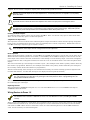
3
+
4
–
Alarm
polarity
shown
BELL
HORN
2K EOLR
Figure 2-5: External Sounder Connections
Supervising the Notification Appliance Circuits
To wire the NAC using the supervision feature, perform the following steps:
Step
1
Action
Install a 2K EOL resistor (Model EOLR20, supplied) across the last notification appliance on the Notification
Appliance Circuit.
2
Program Zone 6 with a 24-hour response type.
IMPORTANT – Supervision must be enabled.
The Notification Appliance Circuits will not respond unless the zones are assigned to them. For fire alarms, the
system displays “FIRE ALARM SILENCED.” This message also displays if the Notification Appliance Circuit is not
supervised.
Auxiliary Relay Connections
The 5110XM provides on auxiliary relay output which may be configured as one of the following:
Wet 12VDC form C relay output
Dry, unsupervised form C relay with contacts rated at 30VAC/VDC, 2A max. resistive loads
The relay (terminal 6) is set at the factory for a 12V nominal (10-14VDC) output, providing 350mA max standby
current/1A max alarm current.
The total standby current that can be drawn from the auxiliary relay and auxiliary power outputs cannot exceed
350mA. The total alarm current that can be drawn from these outputs plus the bell output cannot exceed 1A.
If configuring the relay as a dry, form C relay output, cut the red jumper labeled W3 on the PC board.
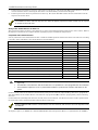
Wiring the Auxiliary Relay
The figures that follow show how to wire the auxiliary relay output for unsupervised alarm output and for 4-wire smoke
detector power usage.
2-7
5110XM Installation and Setup Guide
ALARM
Terminal 18
6
GROUND
N.C.
NOTES:
Use non-polarized indicating
devices.
Wiring is not supervised.
Take care not to exceed the
terminal 6 and overall system
alarm current ratings.
(1A max)
7
POLE
N.O.
5
AUX RELAY
FACTORY DEFAULTS
Set for alarm activation ( 34=1)
No zones trigger by default
(Must program 85, 86)
16 min. timeout ( 31=4)
Note: The control provides 12VDC power on terminal
6 when the red jumper (W3) is intact.
5110XM-001-V0
Figure 2-6: Wiring the Auxiliary Relay Output For Unsupervised Alarm Output.
RESET
5
6
TO
HARDWIRED ZONE (ZN 1-5)
7
18
GROUND
N.C.
POLE
EOLR RELAY
BRK A77-716B
4-WIRE
SMOKE
DETECTOR
EOLR
5110XM-002-V0
Figure 2-7: Wiring the Auxiliary Relay Output For 4-Wire Smoke Detector Power Usage.
Programming the Auxiliary Relay
The auxiliary relay may be programmed for one of the following options:
Trouble/Supervisory Activation
Battery Saver
Alarm Activation, silenced by [user code] + OFF
Alarm Activation, silenced by [user code] + [#] + [67]
4-Wire Smoke Detector Reset
These options are described as follows:
Trouble/Supervisory Activation (34 = 0): Steady activation in response to any zone or system related trouble
condition or to any fire supervisory condition. Remains activated until all fault conditions have been corrected and the
Silence/Reset button has been pressed or the user code + [OFF] has been entered.
Alarm Activation, silenced by [user code] + [OFF] (34 = 1): Steady activation in response to an alarm on one,
some or all zones, as selected in fields 85 and 86. If selected, the auxiliary relay remains activated until Aux. Relay
Timeout (31) or until the Silence/Reset button has been pressed or until the User Code + [OFF] has been entered.
4-Wire Smoke Detector Reset (34 = 2): Momentary (6 second) activation at second entry of User Code + [OFF]
sequence which interrupts power to 4-wire smoke detectors connected to hard-wired zones (zones 1-5), allowing the
detectors to be reset following an alarm. Power to 4-wire smoke detectors should be wired to the auxiliary relay as
shown above.
Battery Saver Option (34 = 3): When this function is selected, the auxiliary relay will normally be activated (i.e.
N.O. and pole contacts will be connected, N.C. contact will be open) and will de-activate 4 hours after the start of an AC
power failure. Using this feature, non-critical loads (such as supplementary keypads) which do not need to be supported
for the full 24 hour battery backup period can be disconnected from the auxiliary outputs, allowing a smaller capacity
battery to be used. The relay re-activates within a few seconds after AC power restores.
Alarm Activation, silenced by [user code] + [#] + [67] (34 = 4): Steady activation in response to an alarm on one,
some or all zones, as selected in fields 85 and 86. If selected, the auxiliary relay remains activated until the User
Code + [#] + [67] has been entered. When this function is used, the auxiliary relay can be used for elevator recall or
ventilator shutdown on fire alarms.
Telephone Line Connections
The 5110XM provides two supervised dialer outputs: the main dialer and the back-up dialer. In fire installations, both
outputs must be connected to separate telephone lines providing loop start service.
Connect the main dialer and back-up dialer (if used) outputs to telephone company lines using the RJ31X cables
2-8
Section 2 – Installing the Control
supplied. Do not connect to telephone company lines, which provide ground start service.
DO NOT connect both outputs to the same telephone line. A secondary phone line is required in case of primary
phone line failure.
To prevent the risk of shock disconnect the telephone lines at the Telco jack prior to servicing this control.
If the control is connected to a PBX telephone line, make sure that the PBX system has a backup power supply that
can support it for at least 24 hours (central station usage) or 60 hours (remote station usage). Many PBX systems
DO NOT have power backup and will cause communication failures when power is lost.
Enabling the Dialer Outputs
To enable the dialer outputs, entries must be made in field 79. Enter 1 in the first entry space to enable main dialer.
Enter 1 in the second entry space to enable backup dialer.
Telephone Line Supervision
The supervision circuits on both the main and backup dialer outputs will indicate a fault when the tip/ring voltage falls
below 2 volts, provided that their supervisory zones are enabled (zones 11 and 12, respectively). Enable these zones in
field 56 and assign a response type of 19 (24-hr. trouble).
UL
In fire installations, both outputs must be configured for line fault supervision.
Dialer Operation
When only the main dialer is enabled (1, 0 in field 79), the 5110XM will attempt to route all calls over the main output.
When both main and back-up dialers are enabled (1,1 in field 79), the 5110XM will attempt to route all calls over the
main output unless a fault is detected, at which time it will attempt to use the back-up output. Line faults will light the
line fault indicator and, if a keypad is installed, will result in a zone 11 main dialer fault or zone 12 back-up dialer fault
display.
The control will make up to ten attempts to transmit a report. (Ten attempts will be made to primary number when only
this number is programmed. Otherwise, five attempts will be made to the primary number followed by five attempts to
the secondary number when both numbers are programmed.)
After the tenth attempt, if the message is not transmitted successfully, the control will hang-up and will light the builtin Comm Fail indicator. A Comm Fail message is also displayed at the keypads (if installed).
The system will not switch to the backup dialer unless it detects a fault (less than 2 volts) on the main telephone
line. This means that if a report does not go through on the main phone line due to a programming error, the
backup dialer will not be activated.
The 5110XM will transmit reports in the following order: alarms (fire, emergency), fire supervisories and troubles, then
the remaining types of messages.
Reporting Formats
The system supports ADEMCO Low Speed 3+1; 4+1; 4+2; Sescoa/Radionics 3+1; 4+1; 4+2; ADEMCO 4+2 Express;
ADEMCO Contact ID formats.
Wiring Devices to Zones 1-5
The maximum zone resistance is 300 ohms for zones 1-4, and 100 ohms for zone 5 (excluding the 2K EOL
resistor).
When used as a slave DACT for a listed FACP, wire the FACP's alarm, supervisory and trouble contacts to the 5110XM's
hardwired zones (terminals 9-16). Fire alarm initiating devices such as smoke detectors should be wired to the FACP
and not the 5110XM. When used as a stand alone control, wire alarm initiating devices to the 5110XM's hardwired
zones. See the summary of connections diagram.
2-9
5110XM Installation and Setup Guide
Connect closed circuit devices in series in the high (+) side the loop. The 2,000 ohm EOL resistor must be connected
in series with the devices, following the last device. See the Summary of Connections diagram.
Connect open circuit devices in parallel across the loop. The 2,000 ohm EOL resistor must be connected across the
loop wires at the last device.
If the EOLR is not at the end of the loop, the zone will not be properly supervised, and the system may not respond
to an open circuit on the zone.
Wiring 4-Wire Smoke Detectors on Zones 1-5
The system will support as many 4-wire detectors as can be powered from Auxiliary Relay Power on the control. Refer to
the detector’s instructions for complete details regarding its proper installation and operation.
Compatible 4-Wire Smoke Detectors
Use any UL Listed 4-wire smoke detector that is rated for 12VDC operation and that has alarm reset time not exceeding
6 seconds. Some compatible 4-wire smoke detectors are listed below.
DETECTOR TYPE
MANUFACTURER
MODEL #
4-Wire Photoelectric Smoke Detector
DSC
FSA-410B
4-Wier Photoelectric Smoke Detector w/Heat Detector
DSC
FSA-410BT
4-Wire Photoelectric Smoke Detector w/Sounder & Heat Detector
DSC
FSA-410BST
4-Wire Photoelectric Smoke Detector w/Aux. Relay & Heat Detector
DSC
FSA-410BRT
4-Wire Photoelectric Smoke w/Aux. Relay, Sounder & Heat Detector
DSC
FSA-410BRST
End of Line Power Supervision Relay for FSA-410 Series Smoke Detectors
DSC
RM-2
Polarity reversal module for FSA-410 series Smoke Detectors
DSC
PRM-4WC
4-Wire Photoelectric Smoke Detector
System Sensor
4W-B
4-Wire Photoelectric Smoke Detector w/Heat Detector
System Sensor
4WT-B
4-Wire Photoelectric Smoke Detector w/Sounder & Heat Detector
System Sensor
4WTA-B
4-Wire Photoelectric Smoke Detector w/Aux. Relay & Heat Detector
System Sensor
4WTR-B
4-Wire Photoelectric Smoke Detector w/Aux. Relay, Sounder & Heat Detector
System Sensor
4WTAR-B
4-Wire Photoelectric Smoke Detector w/Aux. Relay, Sounder & Isolated Heat Detector
System Sensor
4WITAR-B
4-Wire Photoelectric Air Duct Smoke Detector, Extended Air Speed Range
System Sensor
DH100ACDCLP
4-Wire Ionization Air Duct Smoke Detector
System Sensor
DH100ACDCI
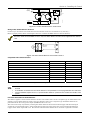
UL
Power to 4-wire smoke detectors must be supervised with an EOL device relay module connected as shown in
Figure 2-8).
A combination of heat detectors and smoke detectors is not permitted on a zone programmed for fire verification.
Fire installations require the use of a synchronization module to synchronize the sounders and strobes on the
system.
Connect 12 volt power for the detectors from Auxiliary Relay Power terminals 7 (+) and 18 (-). Be sure to program the
Aux Power Relay for the smoke detector reset function in program field 34. Observe proper polarity when connecting
detectors.
Connect detectors (including heat detectors, if used) across zone terminals. All detectors must be wired in parallel with
the 2,000 ohm resistor wired in parallel at the last device in the loop.
Remove 2000 ohm EOL resistor if connected across the zone terminals, and connect it across the loop wires at the
last detector.
To supervise power, you MUST use a UL listed End-Of-Line Power Supervision Relay (i.e. System Sensor No. ELOR-1).
2-10
Section 2 – Installing the Control
+
17
_
18
BLK
+
_
+
4-WIRE SMOKE
OR COMBUSTION
DETECTORS
+
_
_
VIOLET
TO HI SIDE OF
_
EOL
POWER
SUPERVISION
RELAY
MODULE
EOLR-1
2000
OHMS
EOLR
+
ZONE 5
TO LO SIDE
RED
HEAT
DETECTOR
HEAT
DETECTOR
4_wiresmk-009-V1
AUX PWR
OUTPUT
TERMINALS
Figure 2-8: 4-Wire Smoke Detector Connections
Wiring 2-Wire Smoke Detectors to Zone 5
Connect up to 16 of the 2-wire smoke detectors listed below across zone 5 terminals 15 (+) and 16 (–).
Observe proper polarity when connecting the detectors. Connect the EOL resistor at the last detector.
Due to the alarm current available on zone 5, only one smoke detector at a time can be supported in the alarmed
state.
ZONE 5
SMOKE
2000 OHMS
EOLR
15
2-WIRE SMOKE
DETECTOR
16
2_wiresmk-003-V0
Figure 2-9: 2-Wire Smoke Detector Connected to Zone 5
Compatible 2-Wire Smoke Detectors
DETECTOR TYPE
MANUFACTURER
MODEL #
2-Wire Photoelectric Smoke Detector
DSC
FSA-210B
2-Wire Photoelectric Smoke Detector w/Heat Detector
DSC
FSA-210BT
2-Wire Photoelectric Smoke Detector
System Sensor
2W-B
2-Wire Photoelectric Smoke Detector w/Heat Detector
System Sensor
2WT-B
2-Wire Ionization Smoke Detector
System Sensor
1451 w/B401B base
2-Wire Photoelectric Low-Profile Smoke Detector
System Sensor
2151 w/B401 base *
2-Wire Photoelectric Smoke Detector
ESL
521B
2-Wire Photoelectric Smoke Detector w/Heat Detector
ESL
521BXT
2-Wire Photoelectric Smoke Detector w/Heat Detector
ESL
429AT
* This model may not be used on zones designated as Zone Type 16: Fire with Verification.
UL
These smoke detectors are UL Listed for use with the 5110XM, and are the only 2-wire smoke detectors that may
be used.
A combination of heat detectors and smoke detectors is not permitted on a zone programmed for fire verification.
UL Fire installations require the use of a synchronization module to synchronize the sounders and strobes on the
system.
Fire Alarm Verification for Smoke Detectors
This feature applies to 2-wire smoke detectors wired to zone 5 when zone 5 is set to response type 16. This feature also
applies to 4-wire smoke detectors wired to any zone when the zone is set to response type 16 and the detectors are
powered from the Aux relay power output (field 34 must be set to 2).
The control will verify any alarm by resetting the smoke detectors after the first alarm trigger and then waiting 90
seconds for a second alarm trigger. If the smoke detector does not trigger again, the control will disregard the first
trigger and no alarm signal will occur. This feature eliminates false alarms due to electrical or physical transients.
2-11
5110XM Installation and Setup Guide
Turning Off Fire Alarm Sounding
You can turn off Fire alarm sounding by pressing the Silence/Reset key on the control's pc board or by entering the user's
code + [OFF] key on any keypad. To clear the "Alarm Silenced" message and to reset the detector's alarm, press the
Silence/Reset key or enter the User's Code + [OFF] again.
Determining the Control’s Power Supply Load
In the event of an AC power loss the 5110XM must be supported by a backup, rechargeable 12VDC 7AH min./14AH max.
battery.
The battery's capacity must be sized to provide 24 hours (UL Central Station Fire) or 60 hours (UL Remote Station Fire)
of standby time followed by 6 minutes of alarm time. Use the steps below to calculate the required battery capacity.
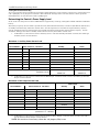
Use the worksheets below to determine the total standby and alarm loads and the required battery capacity. In each
worksheet, multiply each device’s standby and/or alarm current by the number of units used.
1.
In Worksheet 1, enter devices used on Auxiliary Power. Calculate standby and alarm currents, then add to get
Auxiliary Power current subtotal.
Worksheet 1: Auxiliary Power Current Load
Total Current
Device Model #
Device Current X # of Units =
Auxiliary Power Subtotal
(terminals 17 & 18)
2.
Standby
Alarm
350mA max.
350mA max.
In Worksheet 2, enter devices connected to the Bell Output. Calculate alarm currents, then add to get the Bell
Output current subtotal.
Worksheet 2: Bell Output Current Load
Total Current
Device Model #
Device Current X # of Units =
Standby
Alarm
XXXXXX
XXXXXX
XXXXXX
XXXXXX
XXXXXX
XXXXXX
XXXXXX
XXXXXX
Bell Output Subtotal
(terminals 3 & 4 – 1.0A max.)
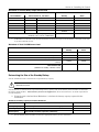
3.
In Worksheet 3, enter devices connected to the Auxiliary Relay Output. Calculate alarm currents, then add to
get the Auxiliary Relay Output current subtotal.
NOTE: No entries are necessary when the red jumper (W3) is cut.
2-12
Section 2 – Installing the Control
Worksheet 3: Auxiliary Relay Output Current Load
Total Current
Device Model #
Device Current X # of Units =
Standby
Alarm
XXXXXX
XXXXXX
XXXXXX
XXXXXX
XXXXXX
XXXXXX
Auxiliary Relay Output Subtotal
(terminals 5, 6, or 7 & 18 – 350mA max.)
4.
In Worksheet 4, enter the total calculated subtotals of all listed outputs from Worksheets 1 through 3, then add
to get the combined current.
Worksheet 4: Total 5110XM Current Load
Total Current
Standby
Alarm
155mA
235mA
Auxiliary Power Subtotal
Bell Output Subtotal
Auxiliary Relay Output Subtotal
5110XM PCB Current (Includes 2-wire smoke detector and LED indicator PCB
currents)
Total Current Load
(350mA max. standby; 1.0A max. alarm)
NOTE: Limit the total power supply standby current to 210mA when a 60-hour standby time is desired.
Determining the Size of the Standby Battery
Use the worksheet below to calculate the required battery capacity.
DO NOT use Gates batteries (sealed lead-acid type). These batteries require a different charging voltage than is
supplied by the panel.
Use Worksheet 5 to determine the required backup battery capacity and use the Battery Selection Table to determine
the battery model number. A dual battery harness is supplied that allows two batteries to be wired in parallel for
increased capacity.
5. Using the total calculated from Worksheet 5, calculate the battery capacity required for the
installation.
Worksheet 5: Battery Capacity Calculation Worksheet
Capacity
Formula
Standby Capacity
Total standby current X 24 or 60 hours X 1.1 contingency factor.
Alarm Capacity
Total alarm curr. X 0.1 (6 min)
Total Capacity
Add standby and alarm capacities (14AH max.)
6.
Calculated Value
Use the Battery Selection Table to select the appropriate battery for the installation.
2-13
5110XM Installation and Setup Guide
Battery Selection Table
Capacity
Recommended Battery
7AH
Yuasa NP7-12
14AH
Yuasa NP7-12
Comment
Connect two in parallel.
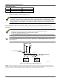
7. Connect the battery, referring to Figure 2-10.
The 5110XM runs a brief battery test once a minute to determine if battery leads are connected and runs an
extended battery test every 24 hours to determine if battery capacity is low (less than approximately 11.5VDC). If
a low battery condition exists the 5110XM's built-in Battery Trouble LED will light and a rapid beeping sound will
be heard from its built-in warning sounder. In addition, if a keypad is on the system, it will be displayed at the
control's keypad(s). These indications will stop when the low battery condition has been restored to normal (for
several minutes).
The 5110XM control comes with a dual battery harness, which allows up to two 12VDC lead acid batteries to be
connected in parallel to the control. Connect the battery(s) to the control using the dual battery harness as shown in the
figure below.
When connecting batteries in parallel:
Use batteries from the same manufacturer and with the same voltage and capacity rating.
Use batteries with approximately the same age and state of charge.
Use cables provided and observe polarity.
It is recommended that all batteries be replaced at the same time, even if only one battery has become weak.
UL
The system provides monitoring of the system battery’s charger circuit. Program field 75 with the charger circuit
failure report code
BATTERY TABS
+ RED
BLK
DUAL BATTERY HARNESS
(SUPPLIED)
D
RE
BL
AC
K
MAIN PCB
+
12V
BATTERY
RE
D
BL
AC
K
NON-REPLACEABLE FUSE
(SEE NOTE 1)
+
12V
BATTERY
(if required)
BATTCONN
Figure 2-10: Connecting the Backup Batteries
NOTE: This fuse is intended to prevent the risk of battery harness flame-out when two batteries are used and one
battery is connected with proper polarity and the other battery is connected with reversed polarity. This fuse will not
open circuit under any other condition. Observe proper polarity when making connections!
2-14
S E C T I O N
3
Programming
Entering and Exiting Programming Mode
Enter Programming mode using either method a or b:
a. Press both the [] and [#] keys at the same time
within 30 seconds after power is applied to the
control.
b. Enter the Installer Code + [8] + [0] keys.
Exit the Programming mode by either method a or b:
a. Press [] + [9] + [8]. Exiting by this method
prevents the Installer Code from being used to reenter Programming mode. Only entry method “a”
can be used to re-enter the Programming mode.
b. Press [] + [9] + [9]. Exiting by this method
permits the installer code to re-enter the
Programming mode.
NOTE:
The system sends Program Mode Entry and Program
Mode Exit report codes to the central station upon
entering and exiting the program mode.
Data Field Programming Mode
In the Programming Mode you may access any field
simply by entering either [] or [#] + the field number:
To write or change information in a field press []
+ the field number (27).
To read the information in a field press [#] + the
field number (#27).
When the entries for a field are completed, the keypad
beeps three times and advances to the next field.
NOTE: If the number of digits that you enter in a data
field is fewer than the maximum permitted (for
example, a phone number), the keypad displays the last
entry and waits. To proceed, enter [] + the next data
field you wish to program.
3-1
5110XM Installation and Setup Guide
Menu Mode Programming
The Menu Mode is an interactive mode through which much of the system’s programming is done. In this mode, there
are “question and answer” prompts. These prompts require a 2-line alpha keypad (6160).
Menu Mode Programming Key Commands
The following is a list of commands used while in Menu Mode Programming.
[]
Serves as ENTER key. Press to have the
keypad the accept entry.
[#]
Backs up to the previous screen.
01-09
All data entries are 2-digit entries.
Press to answer NO
00+[]
Exits menu mode, back into field programming mode, when
entered at the first question for each category.
0
1
Press to answer YES
Zone Number Designations
The 5110XM supports up to 5 zones. The following
table lists the zone numbers, their functions and the
default.
Zone
Function
Default
1-5
Traditional Hardwired Zones
09
6
Bell Supervision
19
7
Keypad Emergency ( + #) (DO NOT USE)
00
Zone
Function
Default
11 &
12
Main and Backup Dialer Supervision
19
13
Auxiliary Relay Disable
-
95
Keypad Emergency ( + 1) (DO NOT USE)
00
96
Keypad Emergency (# + 3) (DO NOT USE)
00
Zone Response Type Definitions
Each zone must be assigned a zone type, which defines
the way in which the system responds to faults in that
zone. Zone types are defined below.
Type 00: Zone Not Used
Program with this zone type if the zone is not used.
Type 06: 24-Hour Silent Alarm (DO NOT USE)
Sends a report to the central station but provides no
keypad display or sounding. Assign this zone type to a
zone containing an Emergency button.
Type 07: 24-Hour Audible Alarm (DO NOT USE)
Sends a report to the central station and provides an
alarm sound at the keypad and an audible external
alarm. Assign this zone type to a zone containing an
Emergency button.
Type 08: 24-Hour Auxiliary Alarm (DO NOT USE)
Sends a report to central station and provides an alarm
sound at the keypad only. (No other Notification
Appliance Circuit is activated.) Assign this zone type to
a zone an Emergency button or one containing
monitoring devices such as water sensors or
temperature sensors.
Type 09: Supervised Fire (Without Verification)
Provides a fire alarm on a short circuit and a trouble
condition on open circuit. A fire alarm produces a three
pulse temporal pattern of the Notification Appliance
Circuit. A zone of this type is always active and can
only be bypassed by using the Installer Code.
3-2
Type 16: Fire With Verification
Provides a fire alarm on short circuit and a trouble
condition on open circuit. An initial short causes 7second smoke detector power reset. Any subsequent
short within 90 seconds causes a fire alarm. A fire
alarm produces a three pulse temporal pattern of the
Notification Appliance Circuit. This type is always
active and can only be bypassed by the Installer Code.
Type 17: Fire Waterflow
Provides a trouble condition (field 32=0) or a supervisory condition (field 32=1) on open circuit and an
alarm on a short circuit that remains longer than the
programmed time delay (field 78). The alarm can be
silenced by either an entry of User Code + [OFF] or
when the zone restores (field 76). This type is always
active.
Type 18: Fire Supervisory
Provides a supervisory response on a short circuit.
Open circuit can be programmed for either a trouble or
supervisory response (field 32). The zone must be
shorted or open longer than the programmed delay time
(field 78) when the delay is enabled (field 57). This
type is always active and can only be bypassed by the
Installer Code. No bell output is activated. This zone
type is usually assigned to a zone containing fire
sprinkler supervisory sensors such as Post-IndicatorValue sensors.
Type 19: 24-Hour Trouble
Provides a trouble response on a short or open circuit.
No alarm sounders are activated.
S E C T I O N
4
Data Field Descriptions
About Data Field Programming
The following pages list this control’s data fields in numerical order. Field numbers are listed in the left column,
followed by a “Title and Data Entries column, which lists the valid entries for each field. Experienced installers can
simply follow this column when programming the data fields. The “Explanation” column provides explanatory
information and special notes where applicable.
NOTE: Refer to the Programming Form for the default values. They are not listed in this section.
Use the Programming Form to record the data for this installation.
UL
The system sends Program Mode Entry and Program Mode Exit report codes to the central station upon
entering and exiting the program mode. (Field programmed in 54 and 55 respectively.)
Programming Data Fields
Data field programming involves making the appropriate entries for each of the data fields. Start Data Field
programming by entering the Installer Code + [8] + [0].
FIELD
TITLE and DATA ENTRIES
EXPLANATION
The Installer Code is a 4-digit code reserved for installation company use.
This is the only code that can be used to enter the Program Mode from the
keypad. This code cannot be used to re-enter Program Mode if Program
Mode is exited by the 98 command. (For security purposes the default
Installer Code should be changed.)
0
200
Installer Code
0
270
Output to AlarmNet
Communicator
Enter 4 digits, 0-9
Enter 0 to Disable, 1 to Enable
If the output to the Communicator is selected here, all messages that are
programmed to go to the primary telephone line receiver will also be sent to
the AlarmNet Communicator connected to the keypad terminals.
These messages will always be in Contact ID format (not affected by entry in
field 46). The data line is supervised as well as certain functions in the
radio. If communication is lost or a trouble develops, a message is sent via
both radio and telephone to the central station.
NOTES:
Normal trouble restore report (71) is sent on restore of the condition.
The Radio should be programmed for device address 3.
0
300
Alarm Bell Timeout
0
310
Auxiliary Relay Timeout
0 = no timeout, 1 = 4 minutes
2 = 8 minutes, 3 = 12 minutes
4 = 16 minutes
0 = no timeout
1 = 4 minutes
2 = 8 minutes
3 = 12 minutes
4 = 16 minutes
Defines the length of time the Alarm Bell Output and the keypad’s sounder will
sound for all audible alarms.
Must be a minimum 6 minutes for UL commercial fire installations.
Defines the length of time the Auxiliary Relay Output will sound for audible
alarms.
Must be a minimum 6 minutes for UL commercial fire installations.
4-1
5110XM Installation and Setup Guide
FIELD
TITLE and DATA ENTRIES
EXPLANATION
If 1, the system produces a supervisory condition on both an open and a
short. If 0, the system produces a trouble condition on an open and a
supervisory condition on a short.
0
320
Supervisory on Open/Short
0
330
Backup TouchTone
(Backup Dialer)
0 = trouble on open/supervisory on short
1 = supervisory on open/supervisory on short
Select the dialing method for the backup dialer.
0 = pulse
1 = touchtone
0
340
Auxiliary Relay Function
Selection
0 = trouble/supervisory
1 = alarm, silenced by Silence/Reset
Button or User Code + OFF
2 = smoke detector reset
3 = battery save
4 = alarm, silenced by User Code + # + 67
PABX Access Code
0
400
0
410
0
420
0
430
Subscriber’s Account Number
0
450
Phone Sys
(Main Dialer)
Enter 0-9; #11 for , #12 for #, #13 for a
2.5-second pause.
Primary Phone Number
Enter 0-9; #11 for , #12 for #, #13 for a
2.5-second pause.
Secondary Phone Number
Enter 0-9; #11 for , #12 for #, #13 for a
2.5-second pause.
Enter 0-9; #11 for B, #12 for C, #13 for D,
#14 for E, or #15 for F
Select the condition that will trigger the auxiliary relay.
NOTES:
Smoke detector reset triggers the relay momentarily (approximately 6
seconds) on the second User Code + OFF entry.
Battery save is used to disconnect power from non-critical loads 4 hours after
AC loss.
When option 1 or 4 is selected, program fields 85 and 86 to select which
zones will trigger the auxiliary relay. When option 1 is selected, program
auxiliary relay timeout in field 31.
This field is used to enter up to four numbers representing the prefix needed
to obtain an outside Telco line. If not required, enter nothing and proceed to
next field.
Enter the primary central station phone number, up to 12 digits. This is the
phone number the control will use to transmit Alarm and status messages to
the central station. Do not fill unused spaces.
NOTE: Backup reporting is automatic only if a secondary phone number is
entered.
Enter the secondary phone number, up to 12 digits. The secondary phone
number is used if communication on the primary number is unsuccessful, or if
split/dual reporting is desired. Do not fill unused spaces.
Enter a 3- or 4-digit (depending on report format) primary subscriber account
number. If a 3-digit account number is to be used, enter data only in the first 3
locations, and enter in the fourth location.
Select the dialing method for the main dialer.
0 = pulse
1 = touchtone
0
4-2
460
Report Format
0 = 3+1, 4+1 ADEMCO Low Speed;
1 = 3+1, 4+1 Radionics Standard;
2 = 4+2 ADEMCO Low Speed;
3 = 4+2 Radionics Standard;
6 = 4+2 Express;
7 = Contact ID;
8 = 3+1, 4+1 ADEMCO Low Speed
Expanded;
9 = 3+1, 4+1 Radionics Expanded
Enter the reporting format for both the primary and secondary telephone
numbers.
NOTE: The Fire Bell Silence message is always sent in Contact ID regardless
of the choice selected for this field.
Section 4 – Data Field Descriptions
FIELD
TITLE and DATA ENTRIES
EXPLANATION
470
Split/Dual Reporting
Select the type of split/dual reporting for system communication.
0
490
Periodic Test Report
0
500
Sescoa/Radionics Select
0
540
Program Mode Entry Report
Code
Enter the report code when the program mode is accessed.
0
550
Program Mode Exit Report Code
Enter the report code when the program mode is exited.
0
560
Zone Assignment/Alarm Report
Codes
See the SECTION 5: Menu Mode Programming for detailed information on
zone programming.
0
570
Zone Type 18 Delay Enable
If enabled, the system uses the delay programmed in field 78 before a
supervisory condition is annunciated for zone type 18. The fault condition
must be present for the entire delay.
0 = backup reporting only
1 = alarm, alarm restore, reports to primary,
all others to secondary
2 = all except test reports to primary, test to
secondary
3 = alarm, alarm restore, reports to primary,
all reports to secondary
4 = all except test reports to primary, all
reports to secondary
5 = all reports to both primary and secondary
0 = none
1 = 24 hours
2 = weekly
3 = 30 days
0 = disable
1 = enable
0 = disable, ignore delay in field 78
1 = enable, use delay in field 78
Select the desired test report interval.
Must be a 1 for UL commercial fire installations.
NOTES: Program the Test Report Code in field 64 and the Off-Normal Test
Report Code in field 84.
If disabled, selects Radionics, which uses hexadecimal 0-9, B-F reporting.
If enabled, selects Sescoa, which uses only numeric reporting (0-9).
NOTE: The selection applies to both primary and secondary phone numbers.
To Program System Status, Trouble, and Restore Report Codes (54, 55, 58 – 74)
The following is a set of guidelines to be used for programming report codes. The actual digits that you enter depend upon the particular
installation, and should be in agreement with you and the central station office receiving the signals. Use these guidelines to program this
entire section.
With a 3+1 or 4+1 Standard Format: Enter a code in the first box: 1–9, A, B, C, D, E, or F. Enter "#+10" for A (this reports a “0” on some
receivers), "#+11" for B, "#+12" for C, "#+13" for D, "#+14" for E, "#+15" for F.
An entry of "0" in the first box will disable a report.
An entry of "0" in the second box will result in automatic advance to the next field when programming.
With an Expanded or 4+2 Format: Enter codes in both boxes (1st and 2nd digits) for 1–9, or A–F, as described above.
An entry of "0" in the first box will disable a report.
An entry of "0" in the second box will eliminate the expanded message for that report.
With ADEMCO Contact ID Reporting: Enter a digit in the first box to enable the zone to report. Use a different digit for each zone until
you have used up available digits. If the number of zones exceeds the number of available digits, begin with digit 1 again. This is an
"enabling" code only and is not the actual code sent to the central station office. Entries in the second boxes will be ignored. For system
status (non-alarm) codes, enter a “1” in the first box for all the system conditions you want to send to the central station.
An entry of "0" in the first box will disable a report.
0
580
Supervisory Report Code
Enter the report code for a supervisory condition.
Note: In Low Speed format (4+2), the field 58 Supervisory Report Code is
sent for a Zone Type 18. The values entered in 56 Zone Programming are
overridden.
0
590
Supervisory Restore Report
Code
Enter the report code for the restore of a supervisory condition.
4-3
5110XM Installation and Setup Guide
FIELD
TITLE and DATA ENTRIES
EXPLANATION
0
600
Trouble Report Code
Enter the report code for a trouble condition.
0
610
Bypass Report Code
Enter the report code when a zone is manually bypassed.
0
620
AC Loss Report Code
Enter the report code for an AC power loss condition. This report is sent at a
random time between 1 and 3 hours after AC power is lost. If the AC restores
before the report is sent, no AC loss report is sent.
0
630
Low Battery Report Code
Enter the report code for a system low battery condition.
0
640
Normal Test Report Code
Enter the report code for a normal test report.
0
690
Group Restores for Trouble,
Bypass
If enabled, the system sends the restore report only after all zones are
restored. If disabled, the system sends the report after each individual zone
restores.
0 = disable
1 = enable
In the event that multiple zone or system troubles have occurred after all
zones are restored, a single Trouble Restore (CID R380 or for Low Speed
whatever is programmed in *71) will be sent. These conditions include ZT18,
ZT19, AC Loss, Low Bat, Dialer, Ground Fault. Alarms are not affected.
0
700
Alarm Restore Report Code (1st
digit)
Enter the first digit of the alarm restore report code. The second digit is
automatically sent as the 2nd digit of the zone alarm report code programmed
in field 56 for that zone, if expanded or 4+2 format is selected.
0
710
Trouble Restore Report Code
Enter the restore report code for a restoral of a trouble condition.
0
720
Bypass Restore Report Code
Enter the restore report code when the bypass of a zone is removed.
0
730
AC Loss Restore Report Code
Enter the restore report code for a restoral of an AC loss condition.
0
740
Low Battery Restore Report Code
Enter the restore report code for a restoral of a system low battery condition.
0
750
Charger Fail Report Code
Enter the report code when the system detects a system battery’s charger
circuit failure.
NOTES:
The system sends the Trouble Restore report code (field 71) upon restoral
of the charger circuit.
The system displays “CHARGER FAIL” when the system detects a system
battery’s charger circuit failure.
0
760
Waterflow Alarm Silencing
Select how the Waterflow zone type will be silenced.
NOTE: This feature may be set to 1 only by permission of the local authority.
0
770
Alarm Bell Sound
Select the alarm output sounding.
0 = temporal pulse
1 = steady
NOTE: For certain applications (ex. using a Sync module), a steady output
must be selected.
0
780
Zone Types 17 & 18 Delay
Select the delay time for zone types 17 and 18. The zone must be faulted for
entire delay time before an alarm or supervisory condition occurs. This may
prevent alarms due to minor fluctuations in waterflow.
NOTES:
For type 18, enable the delay in field 57.
The combined sensor and programmed delay must not exceed 90 seconds.
4-4
0 = silenced by User Code + OFF
1 = silenced when zone restores
Enter 01-99 seconds
Enter 00 for no delay
Section 4 – Data Field Descriptions
FIELD
TITLE and DATA ENTRIES
EXPLANATION
This field has two entries, one for each dialer (main and backup). Enter 1 if
the dialer is being used.
0
790
Main/Backup Dialer Enable
0
820
Alpha Programming
See the SECTION 5: Menu Mode Programming for detailed information on
alpha programming. Alpha programming can also be done in field 56.
0
840
Miscellaneous Report Codes
This field has three 2-digit entries. The first is for Fire Walk Test Start, the
second for Fire walk Test End, the third for Off-Normal Dialer Test. See the
box above field 57 for programming information.
0
850
Zones 1-7 Bell & Auxiliary Relay
Activation
Select which output, if any, each zone activates upon an alarm, trouble or
supervisory condition. There are seven entries in this field, one for each zone.
0 = disable
1 = enable
0 = none
1 = bell only
2 = auxiliary relay only
3 = bell and auxiliary relay
0
860
Zones 10-12, 95 and 96 Bell &
Auxiliary Relay Activation
0 = none
1 = bell only
2 = auxiliary relay only
3 = bell and auxiliary relay
0
940
0
950
0
960
Download Phone Number
Enter 0-9; #11 for , #12 for #, #13 for a
2.5-second pause.
Ring Detection Count
Enter 0 to disable ring detection.
Enter 1-9, #10, #11, #12, #13, #14 for ring
counts of 1-14.
Enter #15 to select Answering Machine
Defeat Mode
Initializes Download ID and
Subscriber Account Number for
Downloading
Select which output, if any, each zone activates upon an alarm, trouble or
supervisory condition. There are six entries in this field, one for each zone.
NOTE: The first entry does not pertain to any zone and must always be
programmed with a 0. The second entry pertains to zone 10.
Enter the download phone number, up to 12 digits. This is the phone number
the control will use to connect to the central computer for downloading. Do
not fill unused spaces.
Enter the number of rings before the control panel picks up the phone line.
In the Answering Machine Mode, the caller should let the phone ring once,
wait for a hang up, and call again within 30 seconds. The system, upon
hearing one ring followed by nothing, does not answer the first call, but
readies itself to pick up on the first ring of the next incoming call that is
received within 30 seconds (i.e., the downloader calling again).
Must be 0 for UL commercial fire installations.
No entry is required.
4-5
5110XM Installation and Setup Guide
4-6
S E C T I O N
5
Menu Mode Programming
General Information
The Menu Mode Programming is an interactive mode through which much of the system’s zone and alpha programming
is done. In this mode, there are “question and answer” prompts. These require a 2-line alpha keypad (6160).
Fields 56 is used to program zone numbers, zone types, and alarm report codes. This field can also be used for
entering alpha descriptors for zones (however, we recommend entering descriptors in menu mode 82.
Field 56 Zone Programming
Enter the programming mode and press 56. The following prompt displays:
PROMPT
EXPLANATION
Zone Number (Zn): Enter the zone number that you wish to program (or [0][0] to leave zone
programming).
Enter Zn Num.
(00 = Quit)
01
Zone 01 entered
Zn
ZT
RC
01
09
10
Zone Type
Zone Type (ZT): Each zone must be assigned to a zone type, which defines the way in which
the system responds to faults in that zone.
Enter the zone type code (or change it, if necessary). Zone types are listed below.
01 Zone Type
Fire
Press []. A summary display will come up, showing the status of that zone's program.
If it is programmed satisfactorily, press [#] to back up one step and enter another zone number, if
desired.
If the zone is not programmed, or you want to change it, press []. A prompt for Zone Type will
appear.
09
00 = Not Used
08 = 24 Hr Auxiliary Alarm
(DO NOT USE)
17 = Fire Waterflow
06 = 24 Hr Silent
(DO NOT USE)
09 = Fire, no verification.
18 = Fire Supervisory
07 = 24 Hr Audible Alarm
(DO NOT USE)
16 = Fire, with verification
19 = 24 Hour Trouble
Zone Type 09 entered
When the display shows the zone type you want, press [] to advance.
Report Code (RC): The report code consists of 2 hexadecimal digits, each in turn consisting of
2 numerical digits. For example, for a report code of "3C", enter [0][3] for "3" and [1][2] for "C".
Enter the numbers and press [] to advance to the Summary Display.
01 Report Code
1st 00 2nd 00
NOTE: Report codes for Fire Alarms cannot be disabled and are always sent to the central
station regardless of the report code entered.
Zn
ZT
RC
01
09
3C
Typical Summary Display. A summary of the programmed values for the selected zone will be
displayed.
If all is okay, press [].
Accepted report code
Program Alpha?
0 = No 1 = Yes
Alpha Programming: For all zone types, the next request is to enter Alpha descriptors for the
zones. The entry may be done now (enter 1), or may be done at a later time via 82 mode
(enter 0).
See Field 82 Alpha Programming for the detailed procedure later in this section.
5-1
5110XM Installation and Setup Guide
PROMPT
EXPLANATION
When all entries to be made for the zone at this time are complete, the next zone number can be
entered for programming, or zone programming can be ended by entering [0][0] as the next
"zone number".
NOTES:
1. In field 56, at the summary line for each zone, the entered values can be checked. If it is
desired to change anything, press [#] to move to the previous entry. Press [#] a number of times
to move to earlier entries. Press [] to move to later entries again.
Enter Zn Num.
(00 = Quit)
2. Zone entries can be reviewed by pressing [#][5][6]. Changes cannot be made here, so this is
safer for review. Enter the first zone number to be viewed and press [#]. To view each zone,
press [#] and the zone number will advance to the next programmed zone. When the end of the
list is reached, press [0][0] to exit. This method of exiting may also be done at any time during
the review.
01 Zone Type
Not Used
00
01 Delete Zone?
1 = Yes 0 = No
To either temporarily or permanently remove a zone from the system go into programming mode
and press [][5][6]. Enter the zone number and press []. At the “Zone Type” prompt, enter
[0][0] and []. This sets the type of the zone to “Not Used”. The next prompt will be "Delete
Zone?".
"Yes" will permanently remove the zone from the system, while "No" will disable it but retain all
data except the original zone type. You can then go back to this zone later and put back an
active Zone Type to re-enable it.
Field 82 Alpha Programming
The alpha keypad used with the 5110XM can have a user-friendly English language description/location of all protection
zones and keypad emergency zones programmed into the system. Each description can be composed of a combination of
words (up to a maximum of 3) selected from a vocabulary of 249 words stored in memory (listed later in this section). In
addition, up to 5 installer-defined words can be added to those already in memory. Thus, when an alarm or trouble
occurs in a zone, an appropriate description for that zone's location will be displayed at the keypad.
NOTE: Alpha descriptor entry can be done locally at the alpha keypad or remotely using downloading software. The
alpha keypad procedure is described below.
The descriptor can be entered when the zone is being defined in field 56 but we recommend that it be done in
field 82.
There are two methods that can be used to enter alpha descriptors via the alpha keypad. The easiest method requires
that you simply enter the 3-digit reference number for the desired word(s). The 3-digit number for each word is provided
in the alpha vocabulary list. An alternate method allows you to pick the desired words by scrolling through the alpha
vocabulary list.
Enter the programming mode and press 56. The following prompt displays:
PROMPT
Program Alpha ?
0=No, 1=Yes 00
Custom Words ?
0=No, 1=Yes 00
Default Descriptor
ZN 01 ZONE 01
5-2
EXPLANATION
Press 82. The “Program Alpha ?” prompt will appear.
Press “1” (Yes). The “Custom Words” prompt will appear.
Press “0” (No). The system will then automatically display the descriptor for zone 1.
NOTE: The procedure for adding custom words to the built-in vocabulary will be found later
under “Adding Custom Words”.
If a descriptor was not entered previously for zone 1, the default descriptor for zone 1 will be displayed.
NOTE: This is a “summary mode”, and no entries can be made. Entries can be made only when
the display contains a flashing cursor, which signifies the “entry mode”.
Section 5 – Menu Mode Programming
PROMPT
EXPLANATION
Flashing Cursor
(system is ready for
entry of word).
To delete or change the default descriptor for zone 1, press plus the same zone number (01).
This will clear that descriptor and gain access to the entry mode with flashing cursor, allowing
changes to be made.
NOTE: If you do not wish to change the existing descriptor for zone 1, enter plus the next
zone number for which you wish to enter (or check) a descriptor. A summary display for that
zone will appear. You must then press plus the same zone number again to gain access to
the entry mode (flashing cursor) for that zone.
ZN 01 A
Flashing Cursor
ZN 01 B ACK
Press # plus 3-digit number for the first word from the “Alpha Vocabulary List”. Example: The
descriptor that we wish to enter for zone 1 is BACK DOOR. From the list, BACK = 015.
Therefore, you would enter # 0 1 5.
NOTE: If you accidentally enter the wrong word, simply press # plus the correct 3-digit number
for the word you want.
ZN 01
BACK
A
Press “6” to accept the selected word and continue.
NOTE: If this is the only word you are using for the descriptor, press “8” instead of “6” to save
that word in memory. The system displays the summary screen.
Flashing Cursor if “6”
is pressed (system is
ready for next word).
ZN 01
BACK
D OOR
Enter the 3-digit number for the next word. In our example, the word is DOOR, whose number is
“061”.
Enter # 0 6 1. This display will appear:
Flashing Cursor
ZN 01
DOOR
BACK
A
Press “6” to accept the selected word.
NOTE: If these are the only words you are using for the descriptor, press “8” instead of “6” to
save them in memory.
Flashing Cursor if “6”
is pressed (system
ready for next word).
The two words in our example have now been entered. Note, however, that up to three words
may be entered (provided the number of characters will fit on the screen). Press “8” to save all
words in memory.
Summary Display
The “A” with the flashing cursor over it will disappear, indicating that the word(s) are stored in
memory for that zone, as shown in the summary display at the left.
To enter a descriptor for the next zone, press plus the desired zone number (e.g., 02). The
summary display following step 4 previously will appear. Now repeat steps 5 through 10 for the
descriptor for the next zone.
ZN 01
BACK
DOOR
Program Alpha ?
0=No, 1=Yes 00
Alpha Pgm
82
To exit the Alpha programming mode, press ”+0+0” at the summary display.
This prompt will be displayed.
Press “0”. This will be displayed.
Press 99 to exit the programming mode.
5-3
5110XM Installation and Setup Guide
Adding Custom Words
You can add up to five installer-defined words to the built-in vocabulary. Each of the five "words" can actually consist of
a "word string" of one or more words, but no more than ten characters can be used for each word or word string.
Custom words must begin with an alphabetic character. If a number or symbol is used as the first
character, the word will not be saved.
Enter the programming mode, press 82 and then press 1. The CUSTOM WORD ? is displayed
Press 1 to select the CUSTOM WORD mode (enter “1”) when the prompt CUSTOM WORD ? is displayed.
When adding Custom Words, the keypad keys perform the following functions:
[3] Advances through the alphabet in ascending order.
[1] Moves through the alphabet in descending order.
[6] Selects desired letter; moves cursor one space to right.
[4] Moves cursor one space to left.
[7] Inserts a space at the cursor location, erasing any character located there.
[8] Saves the new word in the system's memory.
Enter the number ([1]–[5]) of the custom word or word string to be created (for example, if you are creating the first
custom word or word-string, enter [1], for the second, enter [2], etc.). A cursor will now appear at the beginning of the
second line.
One of two methods of entering the custom word's characters can now be used (refer to the CHARACTER LIST
of letters, numbers, and symbols on a following page):
Method 1:
Press the [#] key, followed by the two-digit entry for the first letter you would like to display (e.g., [6][5] for "A"), or...
Method 2:
Use the [3] key to advance through the list of symbols, numbers, and letters. Use the [1] key to move back through the
list.
When you have reached the desired character, press [6] to select it. The cursor will then move to the right, in position
for the next character.
Repeat the previous steps to create the desired word(s). Note, that the [4] key can be used to move the cursor to the left,
if necessary, and that key [7] can be used to enter a blank (or erase an existing character). Remember, no word or wordstring can exceed 10 characters.
Press the [8] key to save the custom word(s) and return to the "CUSTOM WORD?" display.
Repeat the steps for other custom words to be entered. To change a custom word, just overwrite it. If no more are to be
entered now, press [0] to return to the Descriptor entry. The custom word(s) will be automatically added to the built-in
vocabulary.
When zone descriptors are being programmed for the zones, the custom word numbers are 250 to 254 for words 1 to 5,
respectively.
5-4
Section 5 – Menu Mode Programming
Alpha Vocabulary List
(For Entering Zone Descriptors)
000
001
002
003
004
005
006
007
008
009
010
011
012
013
014
015
016
017
018
019
020
021
022
023
024
025
026
027
028
029
030
031
032
033
034
035
036
037
038
039
040
041
042
043
044
045
046
047
048
049
050
051
052
053
(Word Space)
A
AIR
ALARM
ALCOVE
ALLEY
AMBUSH
ANTENNA
AREA
APARTMENT
ART
ATTIC
AUDIO
AUX
AUXILIARY
B
BABY
BACK
BACKUP
BAR
BARN
BASEMENT
BATHROOM
BED
BEDROOM
BELL
BLOWER
BOILER
BOTTOM
BOX
BREAK
BUILDING
BURNER
C
CABINET
CALL
CAMERA
CAR
CASE
CASH
CCTV
CEILING
CELLAR
CENTRAL
CIRCUIT
CLIP
CLOSED
COIN
COLD
COATROOM
COLLECTION
COMBUSTION
COMPUTER
CONTACT
D
DAUGHTERS
DELAYED
DEN
054
055
056
057
DESK
DETECTOR
DIALER
DINING
058
DISCRIMINATOR
059 DISPLAY
060 DOCK
061 DOOR
062 DORMER
063 DOWN
064 DOWNSTAIRS
065 DRAWER
066 DRIVEWAY
067 DRUG
068 DUCT
E
069 EARTH
070 EAST
071 ELECTRIC
072 EMERGENCY
072 ENTRY
074 EQUIPMENT
075 EXECUTIVE
076 EXIT
077 EXTERIOR
F
078 FACTORY
079 FAILURE
080 FAMILY
081 FATHERS
082 FENCE
083 FILE
084 FIRE
085 FLOOR
086 FLOW
087 FOIL
088 FOYER
089 FREEZER
090 FRONT
091 FUR
092 FURNACE
G
093 GALLERY
094 GARAGE
095 GAS
096 GATE
097 GLASS
098 GROUND
099 GUEST
100 GUN
H
101 HALL
102 HEAT
103 HIGH
104 HOLDUP
105 HOUSE
106
107
108
109
110
I
INFRARED
INSIDE
INTERIOR
INTRUSION
J
JEWELRY
154
155
156
157
158
159
160
111
112
113
114
115
116
117
118
119
120
121
122
123
124
125
126
127
128
129
130
131
132
133
134
135
136
137
138
139
140
141
142
143
144
145
146
147
148
149
150
151
152
153
K
KITCHEN
L
LAUNDRY
LEFT
LEVEL
LIBRARY
LIGHT
LINE
LIQUOR
LIVING
LOADING
LOCK
LOOP
LORRA
LOW
LOWER
M
MACHINE
MAGNETIC
MAIDS
MAIN
MASTER
MAT
MEDICAL
MEDICINE
MICROWAVE
MONEY
MONITOR
MOTHERS
MOTION
MOTOR
N
NORTH
NURSERY
O
OFFICE
OIL
OPEN
OPENING
OUTSIDE
OVERFLOW
OVERHEAD
P
PAINTING
PANIC
PASSIVE
PATIO
PERIMETER
161
162
163
164
165
166
167
168
169
170
171
172
173
174
175
176
177
178
179
180
181
182
183
184
185
186
187
188
189
190
191
192
193
194
195
196
197
198
199
200
201
202
203
204
205
206
207
PHONE
PHOTO
POINT
POLICE
POOL
POWER
Q
QUAD
R
RADIO
REAR
RECREATION
REFRIG
REFRIGERATION
RELAY
RF
RIGHT
ROOM
ROOF
S
SAFE
SCREEN
SENSOR
SERVICE
SHED
SHOCK
SHOP
SHORT
SHOW
SIDE
SKYLIGHT
SLIDING
SMOKE
SONIC
SONS
SOUTH
SPRINKLER
STATION
STEREO
STORE
STORAGE
STORY
STRIKE
SUMP
SUPERVISED
SUPERVISION
SWIMMING
SWITCH
T
TAMPER
TAPE
TELCO
TELEPHONE
TELLER
TEMPERATURE
THERMOSTAT
TOOL
TRANSMITTER
208
209
210
211
212
213
TRAP
TRIGGERS
U
UP
UPPER
UPSTAIRS
UTILITY
229
230
V
VALVE
VAULT
VIBRATION
VOLTAGE
W
WALL
WAREHOUSE
WASH
WEST
WINDOW
WINE
WING
WIRELESS
WORK
X
XMITTER
Y
YARD
Z
ZONE (No.)
ZONE
231
232
233
234
235
236
237
238
239
240
241
242
243
244
245
246
247
248
249
0
1
1ST
2
2ND
3
3RD
4
4TH
5
5TH
6
6TH
7
7TH
8
8TH
9
9TH
214
215
216
217
218
219
220
221
222
223
224
225
226
227
228
250
251
252
253
254
Custom Word #1
Custom Word #2
Custom Word #3
Custom Word #4
Custom Word #5
Character (ASCII) Chart
(For Adding Custom Words)
32 (space)
33
!
34
"
35
#
36
$
37
%
38
&
39
'
40
(
41
)
42
*
43
+
44
45
46
47
48
49
51
52
53
54
55
56
,
–
.
/
0
1
3
4
5
6
7
8
57
58
59
60
61
62
63
64
65
66
67
68
9
:
;
<
=
>
?
@
A
B
C
D
69
70
71
72
73
74
75
76
77
78
79
80
E
F
G
H
I
J
K
L
M
N
O
P
81
82
83
84
85
86
87
88
89
90
Q
R
S
T
U
V
W
X
Y
Z
5-5
5110XM Installation and Setup Guide
5-6
S E C T I O N
6
System Communication
General Information
The process of a successful transmission consists of both the method of communication between the control and the central
station receiver and the actual way the information is sent and displayed at the central station.
When the control calls the central station receiver, it waits to hear a “handshake” frequency from the receiver to confirm
that the receiver is on-line and ready to receive its message. Once the control hears the handshake it is programmed to
listen for, it sends its message. The control then waits for a “kissoff” frequency from the receiver acknowledging that the
message was received and understood.
If the handshake frequency is not given or is not understood by the control, the control will not send its message. Once the
handshake frequency is received and understood by the control, the control will send its message. If there is an error in
the transmission (the receiver does not receive a “valid” message), the kissoff frequency will not be given by the central
station receiver.
The 5110XM has two dialers – a main and a back-up dialer. Each of these is enabled separately in program field 79
(both are enabled by default). If enabled, the back-up dialer will only become active when a line fault (voltage on the main
dialer drops below 2 volts) is sensed. The main and backup dialers are supervised by system zones 11 and 12, respectively.
The control will make up to ten attempts to get a valid message through. (Ten attempts will be made to the primary
number when only this number is programmed, and five attempts will be made to the primary number followed by five
attempts to the secondary number when both numbers are programmed). If the control is not successful after its
numerous attempts, the Comm Fail LED will light. If an optional keypad is installed it will display “Communication
Failure” (alpha keypad) or “FC” (fixed-word keypad). Regardless of the format chosen the 5110XM will transmit reports in
the following priority order:
1. Alarms (Fire and emergency)
2. Fire Supervisories and Troubles
3. All remaining reports
Report Code Formats
The following formats are supported by the 5110XM:
3+1, 4+1, 4+2 ADEMCO Standard Low Speed
ADEMCO Contact ID
3+1, 4+1, 4+2 Radionics Standard
3+1, 4+1 ADEMCO Low Speed Expanded
ADEMCO 4+2 Express
3+1, 4+1 Radionics Expanded
Table of Contact ID Event Codes
Code
Definition
110
Fire Alarm Without Verification
111
113
122
123
150
200
301
302
310
314
321
351
352
Smoke Alarm With Verification
Waterflow Alarm
Silent Panic
Audible Panic
24 Hour Auxiliary
Fire Supervisory
AC Power
Low System Battery/Battery Test Fail
Ground Fault
Charger Circuit Fail
Bell Trouble
Main Dialer Trouble
Backup Dialer Trouble
Code
353
373
380
521
524
551
570
602
607
608
627
628
912
Definition
LORRA Trouble
Fire Zone Trouble
Trouble (global)
Bell Bypass
Auxiliary Relay Bypass
Main/Backup Dialer Bypass
Zone Bypass
Normal Dialer Test
Fire Walk Test
Off-Normal Dialer Test
Program Mode Entry
Program Mode Exit
Fire Silence
6-1
5110XM Installation and Setup Guide
6-2
S E C T I O N
7
Downloading Primer
(Remote Downloading is not a UL Listed feature)
General Information
Downloading allows the operator to remotely access,
program, and control the security system over normal
telephone lines, IP, or GSM Communicators. Anything
that can be done directly from the keypad can be done
remotely, using Honeywell’s COMPASS downloading
software. To communicate with the control panel, the
following is required:
1. PC that meets the requirements of the COMPASS
software. Refer to the COMPASS documentation
for those requirements.
2. One of the following modems:
Honeywell CIA
Hayes Smartmodem 1200 (external: level 1.2
or higher; internal: level 1.1 or higher)
Hayes Optima 24 + Fax 96 external
Hayes Optima 336
BizComp Intellimodem 1200 w/volume
BizComp Intellimodem 2400
Other brands are not compatible, even if claimed to
be 100% compatible.
Internal modems must have a 4-position DIP
switch. Modems with a 6-position DIP switch
will not work.
3.
4.
Compass Downloading software revision 1.5.8 or
later.
For IP/GSM downloading, revision 4.0 and above
panels can be downloaded via the ECP bus over the
following Communicators:
7845GSMCF – Revision 2.0.7 or higher
7845iGSMCF – Revision 2.0.7 or higher
7847i – Revision 2.0.7 or higher
8132i – Revision 2.0.91 or higher
Access Security
The following four levels of protection guard the control
against compromise while it is being accessed from a
remote location:
1. Security code handshake: The subscriber’s account
number as well as an 8-digit ID number (known
only to the office) must be matched between the
control and computer.
2. Data encryption: All data that is exchanged
between the computer and control is encrypted to
reduce the possibility of anyone “tapping” the line
and corrupting data.
3. Operator access levels: Operators may be assigned
various levels of access to the downloader, each
having its own log-on code. The access levels allow
the operators read/write capabilities of the
customers’ account information. For a detailed
explanation of the access levels, see the
downloading software User Manual.
NOTES:
When the system is downloading, the keypad
displays “MODEM COMM.”
After each download or save an automatic time
stamp is done, to indicate the last download (or
save) and the operator ID number.
A complete hard copy of each individual account
can be obtained by connecting a printer to the
computer. Refer to your computer Owner’s Manual
or contact your dealer for printer recommendations.
7-1
5110XM Installation and Setup Guide
Getting On-Line with a Control Panel
NOTES:
The Installer must be on premises during a
download.
The control panel must be connected to the existing
telephone line (refer to the SECTION 3: Installing
the Control).
For the initial download to occur, the following
fields must be programmed in the control panel:
95 Ring Count and 96 Initialize DL ID and
Acct #.
When establishing a connection between the computer
and the control panel, the following occurs:
Stage
1
First Communication
The computer calls the control panel. (The
phone number for each customer must be
entered into the customer's account file on
the computer.)
2
The control panel answers the phone call at
the pre-programmed ring count (95) and
executes a handshake with the computer.
3
The panel acknowledges the request and
establishes the session without having to
call back.
4
Once the control panel has been successfully
downloaded, the Central Station operator
may disconnect; once disconnected the panel
will again call the Central Station to report
the Program Mode Exit (UL864 required).
Connecting after the First Communication
7-2
1
After the initial data exchange with
Compass, the panel (and Compass) hangs
up.
2
Compass goes into a "Waiting For Callback"
mode (regardless of the "Waiting For
Callback" setting) see UL note below.
3
The control panel then calls the Primary
Phone (41) to report the "System-Program
Entry" report. After kissoff the panel then
hangs up.
4
The panel then calls back Compass (94) to
complete the session.
UL
It is a UL864 requirement that the panel notify
the Central Station whenever an attempt to
enter the program mode is made.
This is why only the initial session allows an
immediate connection to occur. Disabling the
"System-Program Entry" report (54) will allow
sessions without callback to be made, but
violate the UL864 Standard and should not be
done.
Alarms and Trouble responses and reports
are disabled while you are on-line. All central
station reports are delayed until you complete
the session.
On-Line Control Functions
The following functions can be performed while on-line
with a control panel:
Bypass a zone
Force the system to accept a new program
download
Shut down communication (dialer) functions (for
nonpayment of monitoring fees in an owned
system)
Shut down all system functions (for nonpayment
for a leased system)
Inhibit local keypad programming (prevents
takeover of your accounts)
Command the system to upload a copy of its
resident program to the office
Read: system status, AC power status, list of
bypassed zones, list of zones currently in alarm, list
of zones currently in trouble
S E C T I O N
8
System Operation
User Codes
This system provides 1 Installer Code and 5 Secondary Codes (Users 2-6). These are described below.
User codes are required only if a keypad is installed on the control.
Installer Code
The installer programs the 4-digit Installer Code initially as part of the programming procedure. The Installer Code is
the only code that can allow re-entry into programming mode and also, in normal operation mode, is used to enter the 4digit code for the main user (user #2), which allows access to the normal functions of the system (The main user {#2} may
also enter additional users, 3-6).
Adding, Changing, and Deleting Secondary User Codes
In normal operation mode, the Installer Code (and user code #2) may be used to assign up to 5 additional 4-digit user
codes. It can also be used to remove Secondary Codes from the system (individually).
To assign (or change) a Secondary user code, enter (via keypad):
Installer Code + [CODE key] + User # (2–6) + desired Secondary Code (4-digits)
The system will emit a single beep when each Secondary Code has been successfully entered.
To delete a Secondary user code, enter (via keypad):
Installer Code + [CODE key] + User # (2–6)
NOTES:
All Installer and Secondary user codes permit access to the system for silencing and resetting alarms.
The Installer Code may assign user codes 2-6.
User 2 may assign user codes 3-6.
The Installer Code may bypass ALL zones while users 2-6 may bypass 24 hour non-fire zones only.
The Installer Code may initiate both the Walk Test and Fire Drill Test.
User 2 may initiate the Fire Drill Test only.
Users 3-6 may NOT initiate any of the test modes.
If a Secondary Code is inadvertently repeated for different users, the lower user number will take priority.
User Code Function Summary Table
User #
Enter Program
Mode
Silence Alm,
Trbl, Supv
Add/Change
Users
Bypass
Zones
Enter Test
Modes
1 Installer
Yes
Yes
1-6
All
All
2 Main User
No
Yes
2-6
24 hour only
Fire Drill only
3-6
No
Yes
No
24 hour only
None
8-1
5110XM Installation and Setup Guide
Keypad Functions
The keypad, if used, allows the user to silence alarm and trouble sounders and perform other system functions, such as
bypassing zones, and display zone descriptors. Zone and system conditions (alarm, trouble, and bypass) are displayed in
the Display Window. The system is in the "System Normal" condition when all zones are intact. If NOT, faulted zones
are displayed in numerical order.
System Commands
The following is a brief list of system commands. For detailed information concerning system functions, refer to the
User's Manual.
Summary of System Commands
Silencing Sounders
Code + [OFF] or press Silence/Reset button
Resetting Smoke Detectors and Clearing Alarm
Memory
Code + [OFF] or press Silence/Reset button Twice
Bypassing Zones (installer only function)
Code + [BYPASS] + Zone number(s)
Un-bypassing Zones (installer only function)
Code + [BYPASS] + Zone Number(s)
Fire Walk Test Mode
Installer Code + [#] + [68]
To exit, Code + [OFF]
Fire Drill Mode
Installer or User 2 Code + [#] + [69]
To exit, Code + [OFF]
Emergency Keys
The emergency keys are not programmed or used.
Fixed-Word Keypad Displays
The following is a brief list of fixed-word keypad displays. For detailed information concerning fixed-word keypad
displays, refer to the User's Manual.
Display
Description
FC
Fail Communication – A message to the central station (alarm, trouble, etc.) was not properly received.
CC
Site Initiated Download – A site initiated download occurred.
OC
Open Circuit – The keypad has lost communication with the control panel.
dF
Fire Drill – Displays while the Fire Drill test is in progress.
CF
Fire Walk Test Mode - Displays while the Fire Walk Test is in progress
AA
Program Mode Communicating – Displays while the system communicates the Program Mode Entry
message to the central station.
8-2
S E C T I O N
9
Testing the System
Fire Walk Test
After installation is completed, the 5110XM System should be carefully tested, as follows:
With the System in the "SYSTEM NORMAL" state all zones should be intact. If a fault message is displayed, press the
[] key to display the faulted zone(s). Restore faulted zone(s) if necessary, so that "SYSTEM NORMAL" message is
displayed. 2. Perform the FIRE WALK TEST. This test causes the keypad sounder to beep and the optional alarm
sounders (if connected) to sound momentarily in response to short circuits on zones programmed as types 09, 16, or 17
only. The control will NOT be active during this test
To initiate the ONE MAN FIRE WALK TEST enter the Installer Code + [#] + [68] on any remote keypad. When first
activated alarm sounders (if used) will sound for 3 seconds and all keypad segments will light to verify proper operation.
The control will send a walk test start report to the central station. The following will be displayed on an alpha keypad:
F ire Wa lk T est
I n Pr ogr ess
NOTE: The system displays [TEST CF] on fixed-word keypads
Fault and restore each fire alarm sensor one at a time. Each fault will cause keypads to beep and fire bells (if used) to
sound. (Auxiliary relay will also ding if set for alarm function 1 in field 34 and if assigned in field 85 to the fire zone
that was faulted.) The keypads will also display the faulted zone for as long as the fault remains. The 5110XM will
initiate an automatic smoke detector reset 10 seconds after a smoke detector has been faulted in order to reset that
smoke. Once reset, the keypad display for that zone should clear.
To exit this test enter ANY User Code + [OFF], or the test will automatically terminate after 30 minutes if no faults are
sensed. The control will send a walk test end report to the central station.
Alarm messages will be sent to the central station during the following tests 3 and 4. Notify them in
advance that tests will be in progress.
With the System in the "SYSTEM NORMAL" state, fault one or more zones. Silence alarm sounder(s) by pressing the
silence/reset button or entering the code and pressing OFF (if a keypad is being used).
Check the keypad-initiated alarms (if used) by pressing the appropriate emergency key(s). If the system has been
programmed for audible emergency, the keypad and built-in warning sounder will emit a steady alarm sound, and
ALARM and zone number will be displayed. Silence alarm sounder(s) by pressing the silence/reset button (or
entering the code and pressing OFF). If the control has been programmed for silent alarm, there will be no audible
alarms or displays, but a report will be sent to the central station.
Notify the central station when all tests are finished, and verify results with them.
Dialer Test
The 5110XM may be programmed to send periodic test reports ranging from every 24 hours, weekly, or monthly, as
determined in field 49. The first test report will be sent 12 hours after initial powerup, after exiting the program
mode, or after a download session, whichever is applicable. As long as there are no existing alarm, supervisory, or
trouble conditions present the normal test report will be sent (as programmed in field 64). If alarm, supervisory or
trouble conditions are present at the time of the test report an OFF-NORMAL report will be sent instead (84).
Trouble Conditions
A rapid beeping at the built-in warning sounder (or if used, at the keypad sounder accompanied by the word "CHECK"
on the keypad's display) indicates that there is a trouble condition in the system. The audible warning sound can be
silenced by pressing the Silence/Reset button, or by entering code + [OFF]. Instruct users to call for service immediately
upon seeing any of the following messages. (Also refer to the topic on Troubleshooting.)
9-1
5110XM Installation and Setup Guide
"Check" and "Battery" Displays
When the problem has been corrected, the display can be cleared by pressing the Silence/Reset key or by entering
code plus off a second time.
A display of "CHECK" accompanied by a zone number means there is an open circuit condition on a fire zone, or
that there is a system trouble.
NOTE: Fire troubles will activate the warning sounder and the keypad every 24 hours until the trouble
condition is fixed.
A display of "BAT" (Fixed-word keypads) or “SYSTEM LO BAT” (Alpha keypads) with no zone number
indicates that the system's main standby battery is weak. The built-in battery trouble LED also lights.
Telephone Line Failure
A display of “check 11” or "check 12" (Fixed-word keypads), or “check 11 main dialer” or "check 12 back-up
dialer" (Alpha keypads), indicates that a monitored telephone line has been cut (or disconnected). The keypad will
also produce a trouble sound, (silence by pressing the reset key or entering code plus OFF). The built-in Telco Fault
LED also lights.
Power Failure
Power failure may be exhibited in one of the following ways:
If there is no keypad display at all, operating power for the system has stopped and the system is inoperative.
The built-in AC Power LED also goes off.
If the message "AC LOSS" (Alpha keypads) or "NO AC" (Fixed-word keypads) is displayed, the keypad is
operating on battery power only.
Other Displays (Fixed Word displays are in parenthesis)
Busy-Standby (dI) If this remains displayed for more than 1 minute, the system is disabled.
Modem Comm (CC) The system is in communication with the central station for change of function or status
verification.
Comm. Failure (FC) A communication failure has occurred.
Open Circuit (OC) The keypad is not receiving signals from the control and sees an open circuit.
Long Rng Trbl (bF) Back-up LRR communication failure.
TO THE INSTALLER
Regular maintenance and inspection (at least annually) by the installer and frequent testing by the user are vital to
continuous satisfactory operation of any alarm system.
The installer should assume the responsibility of developing and offering a regular maintenance program to the user as
well as acquainting the user with the proper operation and limitations of the alarm system and its component parts.
Recommendations must be included for a specific program of frequent testing (at least weekly) to insure the system's
proper operation at all times.
Troubleshooting
SYSTEM
SYMPTOM
POSSIBLE CAUSE
REMEDY
1.
Low Battery message on
keypad or battery trouble
LED lit.
1.
"Bat" or “System Low Bat”.
2.
Nuisance or phantom
alarm.
2.
Sensors not properly installed, wired, or 2.
monitored.
3.
"AC POWER" light off.
3.
Interrupted AC power supply.
3.
Check transformer connection and
Power line circuit breaker.
4.
“CHECK” and zone
number 1–5 is displayed.
4.
Control has sensed an open circuit on
one or more zones.
4.
Check the sensor or the loop wiring in
the affected zone. The system will not
display "System Normal" until this
condition is corrected (or the affected
zone is bypassed).
9-2
1.
System battery is low or missing.
Check installation to see if in accordance with established procedure.
Section 9 – Testing the System
CONTROL
SYMPTOM
POSSIBLE CAUSE
REMEDY
1.
Digital control message
not being received.
1a.
1b.
1c.
1d.
5110XM in FIRE WALK TEST mode.
Telephone connection is not secure.
Digital control malfunctioning.
Telephone number in program needs
prefix or access code.
1e. Telephone call to central monitoring
station requires operator assistance.
1a.
1b.
1c.
1d.
2.
5110XM doesn't respond to
keystrokes on keypad.
2a. "CC" or "MODEM COMM" displayed.
2a. System is in communication with downloader at central station. Wait until
download session is finished.
2b. System has just been powered and is
in its 1 minute initialization. To bypass
this time, press '#' + '0'.
2c. Keypads must be set for address 31
(non-addressable mode).
2b. "d1" or "System Busy" displayed.
2c. Keypad address setting incorrect.
Remove from TEST mode.
Check all connections.
Check with a different 5110XM.
Program prefix or access code into the
5110XM.
1e. 5110XM system cannot work in this
situation.
SMOKE DETECTOR
SYMPTOM
1.
Detector alarms, no apparent reason.
POSSIBLE CAUSE
1a. Dust, dirt in sensing chamber.
1b. Improper location.
1c. Unit malfunctioning.
REMEDY
1a. Clean unit's sensing chamber with
vacuum cleaner per unit's instructions.
1b. See unit's instructions for locations to
avoid. Relocate as necessary.
1c. Replace detector.
Contacting Technical Support
PLEASE, before you call Technical Support, be sure you:
READ THE INSTRUCTIONS!
Check all wiring connections.
Determine that the power supply and/or backup battery are supplying proper voltages.
Verify your programming information where applicable.
Verify that all keypads and devices are addressed properly.
Note the proper model number of this product, and the version level (if known) along with any documentation that
came with the product.
Note your Honeywell customer number and/or company name.
Having this information handy will make it easier for us to serve you quickly and effectively.
You may contact Technical Support via Toll-Free Fax. Please include your return fax number. You will receive a reply
within 24 hours.
Technical Support:.....................................................1-800-645-7492 (8 a.m.-8 p.m. EST)
MyWeb Tech: ................ http://www.security.honeywell.com/hsc/resources/MyWebTech/
9-3
5110XM Installation and Setup Guide
9-4
A P P E N D I X
A
Regulatory Agency Statements
The 5110XM may be used as a slave DACT providing central or remote station service for a central or remote station
listed local FACP. The 5110XM may also be used as a stand-alone local, central station or remote station control. Some
comments that apply to these installations are listed below:
When used as a slave DACT:
Wire the 5110XM's hard-wired zones to the FACP alarm, supervisory and trouble contacts. Each zone must have a
2k EOLR installed at the FACP. Program these zones for fire alarm (type 9), fire supervisory (type 18) or trouble
(type 19) response, respectively, as required.
Both dialers must be used. Connect both dialers to separate telephone lines and enable supervision for each dialer.
Program the 5110XM to send fire alarm, supervisory (if used), trouble, AC loss, low battery, normal dialer test and
off-normal dialer test reports. Program dialer test reports to be sent every 24 hours.
Size the back up battery to provide 24-hour standby time for central station installation and 60 hour standby time
for remote station installations.
When used as a stand-alone control:
Wire fire alarm and sprinkler supervisory sensors to the 5110XM's hard wired zones. Each zone must have a 2K
EOLR installed at the last device on the zone wire run. Program these zones for the required response.
Mount one keypad within 3 feet of the control and run wires to the control in conduit.
For local installations wire polarized indicating devices to the bell output and enable the bell supervision.
For central and remote station installations, both dialers must be used. Connect both dialers to separate telephone
lines and enable supervision for each dialer.
Program the 5110XM to send fire alarm, supervisory (if used), trouble, AC loss, low battery, normal dialer test and
off-normal dialer test reports. Program dialer test reports to be sent every 24 hours.
Size the back-up battery to provide 24-hour standby time for local and central station installations and 60 hour
standby time for remote station installations.
Agency Listings
UL864-NFPA 72 Central Station and Remote Station DACT and local, central station and remote station control.
FM pending
CSFM pending
FEDERAL COMMUNICATIONS COMMISSION (FCC) STATEMENTS
The user shall not make any changes or modifications to the equipment unless authorized by the Installation Instructions or User's
Manual. Unauthorized changes or modifications could void the user's authority to operate the equipment.
CLASS B DIGITAL DEVICE STATEMENT
NOTE: This equipment has been tested and found to comply with the limits for a Class B digital device, pursuant to part 15 of the FCC
Rules. These limits are designed to provide reasonable protection against harmful interference in a residential installation. This
equipment generates, uses and can radiate radio frequency energy and, if not installed and used in accordance with the instructions,
may cause harmful interference to radio communications. However, there is no guarantee that interference will not occur in a particular
installation. If this equipment does cause harmful interference to radio or television reception, which can be determined by turning the
equipment off and on, the user is encouraged to try to correct the interference by one or more of the following measures:
Reorient or relocate the receiving antenna.
Increase the separation between the equipment and receiver.
Connect the equipment into an outlet on a circuit different from that to which the receiver is connected.
Consult the dealer or an experienced radio/TV technician for help.
INDUSTRY CANADA (IC) STATEMENTS
This device complies with RSS210 of Industry Canada. Operation is subject to the following two conditions: (1) This device may not
cause harmful interference, and (2) This device must accept any interference received, including interference that may cause undesired
operation.
This Class B digital apparatus complies with Canadian ICES-003.
Cet appareil numérique de la classe B est conforme à la norme NMB-003 du Canada.
A-1
5110XM Installation and Setup Guide
IN THE EVENT OF TELEPHONE OPERATIONAL PROBLEMS
In the event of telephone operational problems, disconnect the control panel by removing the plug from the
RJ31X (CA38A in Canada) wall jack. We recommend that you demonstrate disconnecting the phones on
installation of the system. Do not disconnect the phone connection inside the control panel. Doing so will
result in the loss of your phone lines. If the regular phone works correctly after the control panel has been
disconnected from the phone lines, the control panel has a problem and should be returned for repair. If
upon disconnection of the control panel, there is still a problem on the line, notify the telephone company
that it has a problem and request prompt repair service. The user may not under any circumstances (in or
out of warranty) attempt any service or repairs to the system. It must be returned to the factory or an
authorized service agency for all repairs.
FCC PART 68 NOTICE
This equipment complies with Part 68 of the FCC rules. On the front cover of this equipment is a label that
contains, among other information, the FCC registration number and ringer equivalence number (REN) for
this equipment. If requested, this information must be provided to the telephone company.
This equipment uses the following jacks:
An RJ31X is used to connect this equipment to the telephone network.
The REN is used to determine the quantity of devices that may be connected to the telephone line.
Excessive RENs on the telephone line may result in the devices not ringing in response to an incoming call.
In most, but not all areas, the sum of the RENs should not exceed five (5.0). To be certain of the number of
devices that may be connected to the line, as determined by the total RENs, contact the telephone company
to determine the maximum REN for the calling area.
If this equipment causes harm to the telephone network, the telephone company will notify you in advance
that temporary discontinuance of service may be required. If advance notice is not practical, the telephone
company will notify the customer as soon as possible. Also, you will be advised of your right to file a
complaint with the FCC if you believe necessary.
The telephone company may make changes in its facilities, equipment, operations, or procedures that could
affect the operation of the equipment. If this happens, the telephone company will provide advance notice in
order for you to make the necessary modifications in order to maintain uninterrupted service.
If trouble is experienced with this equipment, please contact the manufacturer for repair and warranty
information. If the trouble is causing harm to the telephone network, the telephone company may request
that you remove the equipment from the network until the problem is resolved.
There are no user serviceable components in this product and all necessary repairs must be made by the
manufacturer. Other repair methods may invalidate the FCC registration on this product.
This equipment cannot be used on telephone company-provided coin service. Connection to Party Line
Service is subject to state tariffs.
This equipment is hearing-aid compatible.
When programming or making test calls to an emergency number, briefly explain to the dispatcher the
reason for the call. Perform such activities in the off-peak hours, such as early morning or late evening.
A-2
CANADIAN EMISSIONS STATEMENTS
This Class B digital apparatus complies with Canadian ICES-003
NOTICE
The Industry Canada Label identifies certified
equipment. This certification means that the
equipment meets telecommunications network
protective, operational and safety requirements as
prescribed
in
the
appropriate
Terminal
Equipment Technical Requirements document(s).
The Department does not guarantee the
equipment will operate to the user’s satisfaction.
Before installing this equipment, users should
ensure that it is permissible to be connected to the
facilities of the local telecommunications
company. The equipment must also be installed
using an acceptable method of connection. The
customer should be aware that compliance with
the above conditions may not prevent degradation
of service in some situations.
Repairs to certified equipment should be
coordinated by a representative designated by the
supplier. Any repairs or alterations made by the
user
to
this
equipment,
or
equipment
malfunctions, may cause the telecommunications
company to request the user to disconnect the
equipment.
Users should ensure for their own protection that
the electrical ground connections of the power
utility, telephone lines, and internal metallic
water pipe system, if present, are connected
together. This precaution may be particularly
important in rural areas.
Caution: Users should not attempt to make such
connections themselves, but should contact an
appropriate electric inspection authority, or
electrician, as appropriate.
NOTICE: The Ringer Equivalence Number
(REN) assigned to each terminal device provides
an indication of the maximum number of
terminals allowed to be connected to a telephone
interface. The termination on an interface may
consist of any combination of devices subject only
to the requirement that the sum of the Ringer
Equivalence Numbers of all the devices does not
exceed 5.
AVIS
L’étiquette d’Industrie Canada identifie le
matériel homologué. Cette étiquette certifie que le
matériel est conforme aux normes de protection,
d’exploitation et de sécurité des réseaux de
télécommunications, comme le prescrivent les
documents concernant les exigences techniques
relatives au matériel terminal. Le Ministère
n’assure toutefois pas que le matériel fonctionnera
à la satisfaction de l’utilisateur. Avant d’installer
ce matériel, l’utilisateur doit s’assurer qu’il est
permis de le raccorder aux installations de
l’enterprise locale de télécommunication. Le
matériel doit également être installé en suivant
une méthode acceptée da raccordement. L’abonné
ne doit pas oublier qu’il est possible que la
conformité aux conditions énoncées ci-dessus
n’empêche pas la dégradation du service dans
certaines situations.
Les réparations de matériel nomologué doivent
être coordonnées par un représentant désigné par
le
fournisseur.
L’entreprise
de
télécommunications peut demander à l’utilisateur
da débrancher un appareil à la suite de
réparations ou de modifications effectuées par
l’utilisateur
ou
à
cause
de
mauvais
fonctionnement.
Pour sa propre protection, l’utilisateur doit
s’assurer que tous les fils de mise à la terre de la
source
d’energie
électrique,
de
lignes
téléphoniques et des canalisations d’eau
métalliques, s’il y en a, sont raccordés ensemble.
Cette précaution est particulièrement importante
dans les régions rurales.
Avertissement : L’utilisateur ne doit pas tenter
de faire ces raccordements lui-même; il doit avoir
racours à un service d’inspection des installations
électriques, ou à un électricien, selon le cas.
AVIS : L’indice d’équivalence de la sonnerie
(IES) assigné à chaque dispositif terminal indique
le nombre maximal de terminaux qui peuvent être
raccordés à une interface. La terminaison d’une
interface téléphonique peut consister en une
combinaison de quelques dispositifs, à la seule
condition que la somme d’indices d’équivalence de
la sonnerie de tous les dispositifs n’excède pas 5.
A-3
5110XM Installation and Setup Guide
A-4
A P P E N D I X
B
Specifications
5110XM Control
Physical:
12-1/2" W x 14-1/2" H x 3" D (318mm x 368mm x 76mm)
Electrical:
Voltage Input:
Rechargeable Back-Up Battery:
Battery Charging Output:
Bell Output:
Auxiliary Power Output:
Auxiliary Relay Output:
Total Output Power:
Standby Time:
Fusing:
From built-in transformer supplying 18VAC at 40VA to 5110XM.
Transformer requires nominal 120VAC, 600mA input.
12VDC, 7AH min., 14AH, max. (Gel type).
Charging Voltage: 13.65VDC, minimum to fully charge battery(s).
12VDC, 1.0A output. Selectable for style Y EOLR supervision (using
EOLR20) or no supervision.
12VDC, 350mA max.
Selectable for wet form C output rated at 12VDC, 350mA standby max/1A
alarm max or dry form C output with contacts rated at 30VAC/VDC, 2A max,
resistive loads.
Combined aux power and aux relay power standby currents cannot exceed
350mA. Combined aux power, aux relay power and bell alarm currents
cannot exceed 1A.
(see Table in Final Powerup section)
PTC circuit protectors on battery input and on aux. power, aux. relay, and
bell outputs.
Communication:
Formats Supported:
ADEMCO 4+2 Express (DTMF, 10 characters per second)
ADEMCO Contact ID Reporting (DTMF, 10 characters per second)
ADEMCO Low Speed 3+1, 4+1, 4+2 (10 pulses per second)
Radionics/SESCOA 3+1, 4+1, 4+2 (20 pulses per second)
Line Seize:
Double Pole
TLM Threshold:
Good line when Tip-Ring voltage exceeds 2V; Bad line when less than 2V
Ringer Equivalence: 0.7B
FCC Registration No. AC398U-68192-Al-E
Maximum Zone Resistance:
Zones 1–4 = 300 ohms excluding EOLR; Zone 5 = 100 ohms excluding EOLR
Built-in Indicators:
Seven LEDs:
Warning Sounder:
AC Power, Comm Fail, Line Fault, Silence Audible, Main Dialer Line Seize, Backup Dialer
Line Seize
Piezo-electric sounder for Alarm, Trouble and Supervisory conditions. Silenced by
pressing the Silence/Reset button, or by Code + [OFF] on a keypad, if used.
Remote Keypads:
Supports up to four 6150 (gray) fixed word and 6160 (gray) alpha keypads depending on system usage and current
loading. When used as a slave DACT, keypads are optional, but may be used for supplemental DACT status
annunciation. When used as a stand-alone control, one keypad, mounted within 3 feet of the control, with the
wiring run in conduit, must be used.
B-1
5110XM Installation and Setup Guide
B-2
Index
Contact ID Reporting.............................................. 4-4, B-1
"AC LOSS" .................................................................... 9-2
Contacting Technical Support ........................................9-3
"Alarm Silenced" message ............................................ 2-8
Current Load Total .......................................................2-10
"BAT"............................................................................. 9-2
Custom Alpha Programming ..........................................5-2
"check 12" ..................................................................... 9-2
Custom Words ....................................................... 5-4, 5-5
"CHECK" ....................................................................... 9-2
"Check" and "Battery" Displays ..................................... 9-2
"NO AC" ........................................................................ 9-2
D
24-hour Silent Alarm Type 06........................................ 3-4
24-Hour Trouble ............................................................ 3-4
DACT .............................................................................1-1
3+1 or 4+1 Standard Format ......................................... 4-4
Data Field Descriptions ..................................................4-1
4-Wire Smoke Detector Reset....................................... 2-4
Default Descriptor ..........................................................5-3
Dialer..............................................................................2-5
A
Dialer Selection ..............................................................4-5
Downloading ..................................................................7-1
Downloading Access Security ........................................7-1
AC Power Input ............................................................. 1-2
Downloading Requirements ................................... 6-1, 7-1
ADEMCO 4+2 Express ...................................1-2, 2-5, B-1
ADEMCO Contact ID.............................................. 1-2, 2-5
ADEMCO Low Speed............................................. 1-2, 2-5
E
Agency Statements ....................................................... A-1
Alarm Output Supervision ............................................. 2-4
Earth Ground................................................................2-30
Alpha Programming....................................................... 5-3
EEROM..........................................................................1-2
Alpha Keypads: ...................................................... 1-1, 2-2
Emergency Keys ............................................................8-2
Alpha Vocabulary List.................................................... 5-3
Entering Programming Mode .........................................3-1
Auxiliary Power Current Load........................................ 2-2
EOL resistor ...................................................................2-7
Auxiliary Power Output.................................................. 1-2
Expanded or 4+2 Format ...............................................4-4
Auxiliary Relay ....................................................... 1-1, 2-4
External Sounders..........................................................2-4
Auxiliary Relay Function Selection ................................ 4-2
B
Back-Up Battery ............................................................ 1-2
Backup Dialer ................................................................ 1-1
Battery Capacity Worksheet........................................ 2-10
Battery Saver Option ..................................................... 2-4
Battery Selection Table ............................................... 2-11
Bell Output Current Load............................................... 2-2
Bell Timeout ...................................... 4-1, 4-2, 4-3, 4-5, 4-6
Bell Output Current Load............................................... 2-2
Bells .............................................................................. 2-4
Built-in Indicators and Switches .................................... 1-2
Busy-Standby ................................................................ 9-2
C
Cabinet Lock ................................................................. 2-1
Callback Requested ............................................... 7-1, 7-2
CANADIAN EMISSIONS STATEMENTS...................... A-3
Central Station .............................................................. 4-4
CHARACTER (ASCII) CHART ...................................... 5-5
CHARACTER LIST ....................................................... 5-4
Charging Voltage .......................................................... B-1
Check 11 ....................................................................... 9-2
Check 12 back-up dialer................................................ 9-2
Circuit breaker protection .............................................. 2-8
Comm. Failure (FC)................................................ 6-1, 9-2
Communication ............................................................. B-1
Communication Formats Supported.............................. 1-2
Communicator Split Reporting ...................................... 4-3
COMPASS downloading software................................. 7-1
CONTACT ID EVENT CODES...................................... 6-1
F
FCC Part 15 STATEMENT ........................................... A-1
FCC PART 68 NOTICE................................................. A-2
Fire (Without Verification) Type 09.................................3-4
Fire alarm sounding .......................................................2-8
Fire Alarm Verification for Smoke Detectors ..................2-8
Fire Supervisory .............................................................3-4
FIRE WALK TEST..........................................................9-1
Fire Waterflow ................................................................3-4
Fire With Verification Type 16 ........................................3-4
Fixed-Word Keypads:.....................................................1-1
FUSING ........................................................................ B-1
G
General Description .......................................................1-1
Getting On-Line with a Control Panel.............................7-2
H
handshake .....................................................................6-1
Hardwire and Optional Expansion Zones.......................1-1
HAYES modem specified by Honeywell.........................1-2
I
Installing the Control's Circuit Board ..............................2-1
Intelligent Test Report ....................................................4-1
Index-1
5110XM Installation and Setup Guide
K
Keypads. ....................................................................... 2-2
Keypad Connections ..................................................... 2-2
Keypad Functions ......................................................... 8-2
Keypad Wiring ............................................................... 2-2
Keyswitch Assignment .................................................. 4-6
kissoff ............................................................................ 6-1
L
LED indicators ............................................................... 1-2
List of Figures....................................................................v
Long Rng Trbl (bF) ........................................................ 9-2
Low Battery message.................................................... 9-2
LRR communication failure ........................................... 9-2
M
Installer Code ................................................................ 8-1
Modem Comm........................................................ 7-1, 9-2
Modems ........................................................................ 7-1
monitored telephone line ............................................... 9-2
Mounting The Control Cabinet ...................................... 2-1
Mounting the Keypads................................................... 2-2
N
No. ELOR-1................................................................... 2-7
Notification Appliance Circuit Supervision ..................... 2-4
O
ONE MAN FIRE WALK TEST ....................................... 9-1
On-Line Control Functions ............................................ 7-2
Open Circuit (OC).......................................................... 9-2
Operator Access Levels ................................................ 7-1
P
PABX Access Code................................................ 2-5, 4-2
Power Failure ................................................................ 9-2
Power Supply Load ....................................................... 2-2
Primary Format ............................................................. 4-3
Primary Phone Number.......................................... 4-2, 4-6
Primary Subscriber’s Account Number.......................... 4-2
Programming.......................................................... 1-2, 3-1
Programming the Auxiliary Relay .................................. 2-4
R
Radionics/SESCOA....................................................... B-1
Regulatory Agency Statements ..................................... A-1
Relay Connections ........................................................ 2-4
Report Code.................................................................. 5-1
Report Codes ................................................................ 4-4
Reporting Formats.................................................. 2-5, 6-1
Index-2
Ring Count .....................................................................7-2
Ring Detection Count .....................................................4-6
S
Secondary Phone Number .............................................4-2
Sescoa/Radionics ........................................... 1-2, 2-5. 4-3
Silence/Reset key ..........................................................2-8
Sirens.............................................................................2-4
Specifications ................................................................ B-1
Standby Battery Size....................................................2-10
System Commands........................................................8-2
SYSTEM LO BAT...........................................................9-2
T
Telephone Line Connections .........................................2-5
Telephone Line Failure ..................................................9-2
Telephone Line Supervision...........................................2-5
TELEPHONE OPERATIONAL PROBLEMS ................. A-2
Temporal Siren Pulse.....................................................4-2
Testing The System .......................................................9-1
TouchTone or Pulse Dial........................................ 4-2, 4-3
Transformer Connections....................................... 1-2, 2-8
Trouble Conditions .........................................................9-1
Trouble/Supervisory Activation.......................................2-4
Turning Off Fire Alarm Sounding....................................2-8
U
UL ..................................................................................1-1
User Codes ....................................................................8-1
V
VOCABULARY LIST ......................................................5-5
W
Warning Sounder ...........................................................1-2
Waterflow Alarm Silence Option.....................................4-5
Wire Run Length/Gauge ................................................2-2
Wiring 2-Wire Smoke Detector.......................................2-7
Wiring 4-Wire Smoke/Combustion Detectors on
Zones 2-7 on Zones 1-5.............................................2-6
Wiring Devices to Zones 1-9 ..........................................2-5
Wiring the Alarm Output.................................................2-4
World Wide Web Address ..............................................9-4
Z
Zone Descriptors)...........................................................5-5
Zone Number (Zn)..........................................................5-1
Zone Number Designations ...........................................3-1
Zone Programming ................................................ 5-1, 5-2
Zone Response Type Definitions ...................................3-4
Zone Type (ZT) ..............................................................5-1
Zone Types 17 & 18 Delay.............................................4-5
WARNING!
THE LIMITATIONS OF THIS ALARM SYSTEM
While this System is an advanced wireless security system, it does not offer guaranteed protection against burglary, fire or
other emergency. Any alarm system, whether commercial or residential, is subject to compromise or failure to warn for a variety of reasons. For example:
Intruders may gain access through unprotected openings or have the technical sophistication to bypass an alarm sensor or
disconnect an alarm warning device.
Intrusion detectors (e.g., passive infrared detectors), smoke detectors, and many other sensing devices will not work without power. Battery-operated devices will not work without batteries, with dead batteries, or if the batteries are not put in
properly. Devices powered solely by AC will not work if their AC power supply is cut off for any reason, however briefly.
Signals sent by wireless transmitters may be blocked or reflected by metal before they reach the alarm receiver. Even if
the signal path has been recently checked during a weekly test, blockage can occur if a metal object is moved into the path.
A user may not be able to reach a panic or emergency button quickly enough.
While smoke detectors have played a key role in reducing residential fire deaths in the United States, they may not activate or provide early warning for a variety of reasons in as many as 35% of all fires, according to data published by the
Federal Emergency Management Agency. Some of the reasons smoke detectors used in conjunction with this System may
not work are as follows. Smoke detectors may have been improperly installed and positioned. Smoke detectors may not
sense fires that start where smoke cannot reach the detectors, such as in chimneys, in walls, or roofs, or on the other side
of closed doors. Smoke detectors also may not sense a fire on another level of a residence or building. A second floor detector, for example, may not sense a first floor or basement fire. Finally, smoke detectors have sensing limitations. No
smoke detector can sense every kind of fire every time. In general, detectors may not always warn about fires caused by
carelessness and safety hazards like smoking in bed, violent explosions, escaping gas, improper storage of flammable
materials, overloaded electrical circuits, children playing with matches, or arson. Depending on the nature of the fire
and/or location of the smoke detectors, the detector, even if it operates as anticipated, may not provide sufficient warning
to allow all occupants to escape in time to prevent injury or death.
Passive Infrared Motion Detectors can only detect intrusion within the designed ranges as diagrammed in their
installation manual. Passive Infrared Detectors do not provide volumetric area protection. They do create multiple beams
of protection, and intrusion can only be detected in unobstructed areas covered by those beams. They cannot detect motion
or intrusion that takes place behind walls, ceilings, floors, closed doors, glass partitions, glass doors, or windows.
Mechanical tampering, masking, painting or spraying of any material on the mirrors, windows or any part of the optical
system can reduce their detection ability. Passive Infrared Detectors sense changes in temperature; however, as the
ambient temperature of the protected area approaches the temperature range of 90° to 105°F (32° to 40°C), the detection
performance can decrease.
Alarm warning devices such as sirens, bells or horns may not alert people or wake up sleepers if they are located on the
other side of closed or partly open doors. If warning devices are located on a different level of the residence from the bedrooms, then they are less likely to waken or alert people inside the bedrooms. Even persons who are awake may not hear
the warning if the alarm is muffled by noise from a stereo, radio, air conditioner or other appliance, or by passing traffic.
Finally, alarm warning devices, however loud, may not warn hearing-impaired people.
Telephone lines needed to transmit alarm signals from a premises to a central monitoring station may be out of service or
temporarily out of service. Telephone lines are also subject to compromise by sophisticated intruders.
Even if the system responds to the emergency as intended, however, occupants may have insufficient time to protect themselves from the emergency situation. In the case of a monitored alarm system, authorities may not respond appropriately.
This equipment, like other electrical devices, is subject to component failure. Even though this equipment is designed to
last as long as 20 years, the electronic components could fail at any time.
The most common cause of an alarm system not functioning when an intrusion or fire occurs is inadequate maintenance. This
alarm system should be tested weekly to make sure all sensors and transmitters are working properly. The security keypad
(and remote keypad) should be tested as well.
Wireless transmitters (used in some systems) are designed to provide long battery life under normal operating conditions.
Longevity of batteries may be as much as 4 to 7 years, depending on the environment, usage, and the specific wireless device
being used. External factors such as humidity, high or low temperatures, as well as large swings in temperature, may all
reduce the actual battery life in a given installation. This wireless system, however, can identify a true low battery situation,
thus allowing time to arrange a change of battery to maintain protection for that given point within the system.
Installing an alarm system may make the owner eligible for a lower insurance rate, but an alarm system is not a substitute
for insurance. Homeowners, property owners and renters should continue to act prudently in protecting themselves and
continue to insure their lives and property. We continue to develop new and improved protection devices. Users of alarm
systems owe it to themselves and their loved ones to learn about these developments.
NOTES
NOTES
NOTES
NOTES
NOTES
NOTES
NOTES
2k
MODEL
EOLR20
6. All Earth Grounds must be wired to cabinet ground post. Use
minimum AWG16 wire.
5. No more than one (1) wire per terminal may be connected.
3. For approved Special Application Notification Appliance Circuits,
the maximum line impedance allowed when the system is fully
loaded to 1.0A for devices that can operate at a minimum of
8VDC is 2.0 ohms. For devices that can operate at a minimum
of 9VDC the maximum line impedance is 1.0 ohms.
2k EOLR is Ademco model EOL20.
4. Use only 14-22 AWG wire.
The combined alarm current drawn from aux power, relay power, and
bell cannot exceed 1.0A.
BELL -
BATT -
BATT +
EARTH
GROUND
W3
(RED)
SILENCE
(YELLOW)
LINE FAULT
(YELLOW)
COMM FAIL
(YELLOW)
RJ31X
DATA IN
N.O.
ZONE 1/ZONE 2 ZONE 1 +
ZONE 2 +
N.O.
N.O.
N.O.
ZONE 4 +
N.C.
N.C.
N.C.
N.C.
2k
2k
2k
2k
2k
PROGRAM USING DELAY TIME MARKED ON DETECTORS.
2K EOLR IS ADEMCO MODEL EOL20.
5110XM-SIMP-V2
ZONE 5 RATINGS: +10-14VDC
+2mA MAX FOR 2-WIRE SMOKE DETECTORS. UP TO 16 DETECTORS OF
TYPE SPECIFIED IN INSTRUCTIONS MAY BE USED.
ZONE RESPONSE: 300-500 MILLISECOND (ALL ZONES).
ZONE RESISTANCE (EXCLUDING EOLR):
+ZONES 1-4: 300 OHM MAX.
+ZONE 5: 100 OHM MAX.
ALL ZONES ARE CLASS B AND PROVIDE STYLE B SUPERVISION.
ZONE NOTES
N.C.
OPTIONAL
REMOTE
KEYPADS
2-WIRE SMOKE DETECTOR LOOP
N.O.
RED
BLACK
GREEN
YELLOW
ZONE 3 +
ZONE 5 +
ZONE 5 -
+
GND
DATA OUT
6150 OR 6160 MAY BE USED
IN CONJUNCTION WITH THE
CONTROL PANEL'S LED
INDICATORS AND
SILENCE/RESET BUTTON.
ONLY A 6160 MAY BE USED TO
PROGRAM PANEL.
AUX POWER RATING: 10-14VDC,
350mA MAX, POWER LIMITED
NOT SUPERVISED (SEE NOTE 2).
ZONE 3/ZONE 4 -
J5
LED INDICATOR BOARD
PLUG BOARD INTO THE
J5 9-PIN HEADER.
MAIN DIALER
PHONE JACK
MAIN
DIALER
LINE
SEIZE
(GREEN)
TROUBLE
(YELLOW)
ALARM
(RED)
SUPERVISORY
(YELLOW)
BACK-UP
DIALER
LINE
SEIZE
(GREEN)
BACK-UP DIALER
PHONE JACK
RJ31X
AC POWER
(GREEN)
SOUNDER SILENCE SWITCH
PUSH ONCE TO SILENCE,
PUSH AGAIN TO RESET
WARNING
SOUNDER ACTIVATES ON ALARMS,
SUPERVISORIES AND TROUBLES
BATT TROUBLE
(YELLOW)
MAKE CONNECTIONS TO SEPARATE
TELEPHONE LINES USING CABLE SUPPLIED.
SUPERVISION IS PROGRAMMABLE.
RELAY
POWER
JUMPER
BELL CIRCUIT SUPERVISION JUMPER
INTACT: SUPERVISED USING 2K EOLR
DO NOT CUT.
AUXILIARY
RELAY
BLACK
ADEMCO 5110XM SIMPLIFIED WIRING DIAGRAM
12V LEAD ACID BATTERY
7 AH MIN/14 MAX.
SEE INSTRUCTIONS FOR
REQUIRED CAPACITY AND
BATTERY MOUNTING
USE BATTERY CABLES
SUPPLIED
8
2. The combined standby current drawn from aux power and relay power
cannot exceed 350mA.
1. Each output may be selected for Style Y supervision or no
supervision. Supervision may be disabled by cutting jumper W2
and programming Zone 6 for no response.
(NOTE 6)
GREEN
N.C.
BELL +
AC Input Power
W2 (WHITE)
AC
TO PC BOARD TERMINAL 8
TO POWER SUPPLY ENCLOSURE
TO FACILITY GROUND
TO CABINET DOOR (NOT SHOWN)
EARTH GROUND INFORMATION
(SEE NOTE 6)
AC
7
NOTES
N.O.
BELL
POLE/RELAY +
HORN
BLUE
BLUE
6
JUMPER W3 CUT: NO VOLTAGE ON TERMINAL 6.
RELAY CONTACT RATING: 30 VAC/VDC,
2A MAX RESISTIVE LOADS.
JUMPER W3 INT ACT: 10-14VDC ON TERMINAL 6
350mA MAX (STANDBY) /1A MAX (ALARM),
POWER-LIMITED (SEE NOTE 2).
USE TERMINAL 18 FOR GROUND RETURN.
AUX RELAY HAS PROGRAMMABLE FUNCTION
(NOT SUPERVISED)
ALL POWER-LIMITED WIRING MUST BE
SEPARATED FROM OTHER WIRING BY
AT LEAST 1/4 INCH (6.4.MM).
ALL CIRCUITS ARE POWER LIMITED EXCEPT
THE OUTPUT OF THE POWER TRANSFORMER
AND BACKUP BATTERIES
For commercial fire, bell timeout must be a minimum
of 6 minutes.
Ratings: 10 - 14VDC, 1.0A max.
See note 1, see instructions for compatible devices.
(NOTE 6)
GREEN
MAINTAIN
MINIMUM 1/4"
SPACING FROM
OTHER WIRING.
CONNECT TO
AC POWER
TERMINALS 1, 2
18VAC, 40VA
SEE AC
TRANSFORMER
CONNECTIONS
ABOVE
(SUPERVISED)
BLUE
WHT
NOTE: USE WIRES RATED
FOR 90C OR HIGHER.
BLUE
BLK
2A CIRCUIT
BREAKER
FIRE CKTS: Supervise using 2k EOLR.
Use polarized sounding devices.
CONNECT TO
A DEDICATED
CIRCUIT
CONNECT TO
PROPER EARTH
GROUND.
120VAC, 60Hz
CABINET GROUND POST
REFER TO SOC LABEL FOR DETAILED INFORMATION
AUX POWER
20
19
18
17
16
15
14
13
5
12
24
11
23
10
2
9
21
RED
DOCUMENTATION AND ONLINE SUPPORT
For the latest documentation and online support information, please go to:
http://www.security.honeywell.com/hsc/resources/MyWebTech/
WARRANTY
For the latest warranty information, please go to:
http://www.security.honeywell.com/hsc/resources/wa/
2 Corporate Center Drive, Suite 100
P.O. Box 9040, Melville, NY 11747
Copyright 2010 Honeywell International Inc.
www.honeywell.com/security
ÊN8026V2VŠ
N8026V2 3/10 Rev B