1
VISTA-128FBPT
VISTA-250FBPT
Commercial Fire and Burglary
Partitioned Security System
with Scheduling
Installation and Setup Guide
800-09617V1 11/12 Rev. B
Table of Contents
• • • • • • • • • • • • • • • • • • • • • • • • • • • • • • • • • • • • • • • • • • • • • • • • •
TABLE OF CONTENTS ....................................................................................................................................... 3
LIST OF FIGURES ................................................................................................................................................ 5
CONVENTIONS USED IN THIS MANUAL ..................................................................................................... 6
UL864 (COMMERCIAL FIRE) COMPLIANCE ............................................................................................... 7
General Requirements .......................................................................................................................................7
Programming Field Settings for UL864 Compliance .......................................................................................7
Programming Field Settings for ULC304 Compliance ................................................................................. 10
SECTION 1: GENERAL DESCRIPTION ........................................................................................................ 11
SIA Installations .............................................................................................................................................. 11
About the VISTA-128FBPT/VISTA-250FBPT ............................................................................................... 11
Features ........................................................................................................................................................... 11
Guidelines for Wiring a System ...................................................................................................................... 15
SECTION 2: PARTITIONING ........................................................................................................................... 17
Theory of Partitioning ..................................................................................................................................... 17
Setting-Up a Partitioned System.................................................................................................................... 17
Common Lobby Logic ...................................................................................................................................... 17
Master Keypad Setup and Operation ............................................................................................................. 19
SECTION 3: INSTALLING THE CONTROL .................................................................................................. 21
Mounting the Control Cabinet ........................................................................................................................ 21
Installing the Cabinet Lock ............................................................................................................................ 21
Mercantile Premises Listing Guidelines ........................................................................................................ 22
Mercantile Safe and Vault Listing Guidelines .............................................................................................. 22
Commercial Fire Guidelines ........................................................................................................................... 23
Installing the Control's Circuit Board ............................................................................................................ 23
Installing the Keypads .................................................................................................................................... 24
Installing External Sounders.......................................................................................................................... 26
Auxiliary Relay Connections........................................................................................................................... 29
Telephone Line Connections ........................................................................................................................... 30
Main Dialer Connections................................................................................................................................. 31
Wiring Burglary and Panic Devices to Zones 1-8 .......................................................................................... 32
Installing V-Plex Devices ................................................................................................................................ 35
Wireless Zone Expansion ................................................................................................................................ 38
Installing Output Devices ............................................................................................................................... 41
Installing a Remote Keyswitch ....................................................................................................................... 43
Installing a Remote Keypad Sounder (For Commercial Burglary use only) ............................................... 44
Communicators Connected to the ECP Bus .................................................................................................. 45
Access Control Using VistaKey ...................................................................................................................... 46
Event Log Connections .................................................................................................................................... 48
RS-232 Connectivity ........................................................................................................................................ 48
Connecting the Transformer ........................................................................................................................... 50
Earth Ground Connections ............................................................................................................................. 50
Determining the Control’s Power Supply Load ............................................................................................. 50
Determining the Size of the Standby Battery ............................................................................................... 55
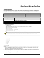
SECTION 4: DOWNLOADING .......................................................................................................................... 59
3
General Information ........................................................................................................................................ 59
Unattended Download (For Burglary Use Only) ........................................................................................... 58
Getting On-Line with a Control Panel ........................................................................................................... 58
Direct-Wire Downloading ................................................................................................................................ 59
Telco Handoff ................................................................................................................................................... 59
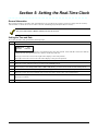
SECTION 5: SETTING THE REAL-TIME CLOCK ....................................................................................... 61
General Information ........................................................................................................................................ 61
Setting the Time and Date .............................................................................................................................. 61
SECTION 6: USER ACCESS CODES .............................................................................................................. 63
General Information ........................................................................................................................................ 63
User Codes and Levels of Authority ............................................................................................................... 63
Multiple Partition Access ................................................................................................................................ 64
Adding a Master, Manager, or Operator Code .............................................................................................. 65
Changing a Master, Manager, or Operator Code .......................................................................................... 66
Deleting a Master, Manager, or Operator Code ............................................................................................ 69
Exiting the User Edit Mode ............................................................................................................................ 69
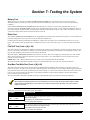
SECTION 7: TESTING THE SYSTEM............................................................................................................. 69
Battery Test ..................................................................................................................................................... 69
Dialer Test........................................................................................................................................................ 69
Fire Drill Test (Code + [#] + 69) ...................................................................................................................... 69
One-Man Fire Walk-Test (Code + [#] + 68) .................................................................................................... 69
Burglary ........................................................................................................................................................... 70
Walk-Test ......................................................................................................................................................... 70
Walk Testing the ‘Smart’ V-Plex Motion Detectors....................................................................................... 71
Armed Burglary System Test ......................................................................................................................... 71
Testing Wireless Transmitters ....................................................................................................................... 71
Trouble Conditions .......................................................................................................................................... 72
To the Installer ................................................................................................................................................ 73
REGULATORY AGENCY STATEMENTS ...................................................................................................... 75
UL Installation Requirements ........................................................................................................................ 75
UL864/NFPA Local Fire .................................................................................................................................. 75
UL864/NFPA Central Station and Remote Station Fire .............................................................................. 75
Commercial Burglary Requirements.............................................................................................................. 75
UL609 Local Mercantile Premises/Local Mercantile Safe & Vault.............................................................. 75
UL365 Police Station Connected Burglar Alarm .......................................................................................... 76
UL365/UL609 Bank Safe and Vault Alarm System...................................................................................... 76
UL1610 Central Station Burglary Alarm ...................................................................................................... 76
ULC Installation Requirements ..................................................................................................................... 76
APPENDIX A: ....................................................................................................................................................... 81
SUMMARY OF SYSTEM COMMANDS ........................................................................................................... 81
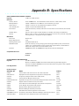
APPENDIX B: SPECIFICATIONS ................................................................................................................... 83
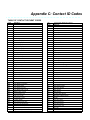
APPENDIX C: ....................................................................................................................................................... 85
CONTACT ID CODES......................................................................................................................................... 85
TABLE OF CONTACT ID EVENT CODES .................................................................................................. 85
Event Log Alpha Descriptors .......................................................................................................................... 86
GLOSSARY ........................................................................................................................................................... 89
INDEX .................................................................................................................................................................... 95
4
List of Figures
• • • • • • • • • • • • • • • • • • • • • • • • • • • • • • • • • • • • • • • • • • • • • • • • •
Figure 1-1: Isolating Fire Devices from Burglary Devices
16
Figure 3-1: Installing the Lock
21
Figure 3-2: Cabinet Attack Resistance Considerations
22
Figure 3-3: Commercial Fire Installation Considerations
23
Figure 3-4: Mounting the PC Board
24
Figure 3-5: Keypad Connections to Control Panel
25
Figure 3-6. ECP Isolator Wiring
25
Figure 3-7. Using a Supplementary Power Supply
26
Figure 3-8: Wiring Auxiliary Relay for Alarm Activation
30
Figure 3-9: Wiring Auxiliary Relay for Smoke Detector Reset
30
Figure 3-10: 2-Wire Smoke Detector on Zone 1 (for zone 2 use terminals 17 and 18)
33
Figure 3-11: 4-Wire Smoke Detectors
34
Figure 3-12: Wiring a Normally Closed Sensor Loop for Tamper Supervision
35
Figure 3-13: Wiring a Normally Open Sensor Loop for Tamper Supervision
35
Figure 3-14: Polling Loop Connections to the Control Panel
36
Figure 3-15: Polling Loop Connections Using One 4297 Extender Module
37
Figure 3-16: Polling Loop Connections Using Multiple Extender Modules
37
Figure 3-17: Installing the 5881ENHC with Tamper Protection
39
Figure 3-18: 5881ENHC RF Receiver (cover removed)
39
Figure 3-19: 4204 Relay Module
42
Figure 3-20: 4204CF Relay Module
42
Figure 3-21: Remote Keyswitch Wiring
44
Figure 3-22: Remote Keypad Sounder Wiring
44
Figure 3-23: Wiring Communicator to Keypad Terminals
46
Figure 3-24: Wiring the VistaKey
48
Figure 3-25: Connecting the Backup Batteries
56
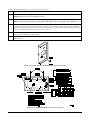
VISTA-128FBPT/ VISTA-250FBPT Summary of Connections Diagram
Inside Back Cover
5
Conventions Used in This Manual
• • • • • • • • • • • • • • • • • • • • • • • • • • • • • • • • • • • • • • • • • • • • • • • • •
Before you begin using this manual, it is important that you understand the meaning of the following symbols (icons).
UL
These notes include specific information that must be followed if you are installing this system for
a UL Listed application.
These notes include information that you should be aware of before continuing with the
installation, and that, if not observed, could result in operational difficulties.
This symbol indicates a critical note that could seriously affect the operation of the system, or
could cause damage to the system. Please read each warning carefully. This symbol also
denotes warnings about physical harm to the user.
ZONE PROG?
1 = YES 0 = NO 0
∗00
Many system options are programmed in an interactive mode by responding to
alpha keypad display prompts. These prompts are shown in a single-line box.
Additional system options are programmed via data fields, which are indicated by a “star” (∗)
followed by the data field number.
PRODUCT MODEL NUMBERS:
Unless noted otherwise, references to specific model numbers represent Honeywell products.
6
UL864 (Commercial Fire) Compliance
• • • • • • • • • • • • • • • • • • • • • • • • • • • • • • • • • • • • • • • • • • • • • • • • •
General Requirements
The VISTA-128FBPT/VISTA250FBPT control panels provide features that allow the system to meet UL864 Commercial
Fire requirements. To meet these requirements, follow the guidelines outlined in this section.
•
•
•
•
•
•
•
•
•
The reporting of bypassed points to the central station must be enabled in Report Code Programming mode.
Fire alarm notification circuits must be supervised (e.g., supervisory zones 970 and 971 for Bell 1 and Bell 2
outputs)
Only one relay of the 4204CF can be programmed for a NAC. If the 4204CF relay is programmed as a NAC, the
stop action must be programmed as a zone type 62, Bell 2 Timeout.
Output devices are not intended for overriding automatic fire and building functions.
Line cut detection must be enabled for both the main and backup phone lines (supervisory zones 974 and 975).
Access Control Devices cannot be used.
Audio Alarm Verification Devices cannot be used.
Remote downloading can only be performed if a service person is at the premises.
All supervision zones for the polling loop, RF receivers, keypads, NAC outputs, and telephone lines that are used,
must be enabled as zone type 19 (24-hour trouble).
Programming Field Settings for UL864 Compliance
NOTICE TO USERS, INSTALLERS, AUTHORITIES HAVING JURISDICTION, AND OTHER INVOLVED
PARTIES
This product incorporates field-programmable software. In order for the product to comply with the requirements
in the Standard for Control Units and Accessories for Fire Alarm Systems, UL 864, certain programming features
or options must be limited to specific values or not used at all as indicated below.
Program feature or option
Permitted in
UL864? Y/N
Possible settings
Settings permitted in UL 864
∗08 TEM PORAL SI REN PUL SE
N
0 = disable
1 = enable
Not used at t his t ime. M ust be set t o
“0” (disable).
∗13 BEL L 1 TI M EOUT
Y
Ent er 01-15 mult iplied by 2 minut es.
00 = no t imeout.
M ust be set to “3” (M inimum of 6
minutes).
∗14 RS232 comm.
N
M ust be set to “0”.
∗17 AC L OSS K EYPAD
SOUNDI NG
N
0 = no
1 = yes
0 = disable
1 = enable
∗19 RANDOM I ZE AC L OSS
REPORT
Y
∗20 TEL EPH ONE M ODUL E
PH ONE CODE
N
∗22 K EYPAD PANI C ENABL ES
(PARTI TI ON SPECI FI C)
N
0 = disable
1 = enable
∗23 M UL TI PL E AL ARM S
(PARTI TI ON SPECI FI C)
N
0 = disable
1 = enable
∗24 I GNORE EXPANSI ON
ZONE TAM PER
N
0 = disable (t amper det ect ion)
1 = enable (no t amper detect ion)
M ust be set to “0” (enabled).
∗26 I NTEL L I GENT TEST
REPORTI NG
N
0 = disable
1 = enable
M ust be set to “0” (disable).
M ust be set to “1” (enabled).
0 = wit hin 2 minutes
1 = 10-40 minut es
2 = 1-3 hour s
3 = 6-12 hour s wit hout Type 13, 1-3
hour s with Type 13
M ust be set to “2”.
1-9 = fir st digit of access code
Not Used. M ust be set to “00”.
∗ or # = second digit of access code
(ent er # +11 for “∗”, or # +12 for “#”)
To disable ent er 00 for the 1st digit
M ust be set to “000” for par t it ion 1
in fire syst ems.
M ust be set to “1” (enabled).
7
Program feature or option
Permitted in
UL864? Y/N
Possible settings
Settings permitted in UL 864
Ent er 0001-9999 for t he test repor t
int erval in hour s.
Ent er 0000 for test report ing.
0 = disable
1 = enable
0 = disable
1 = enable
0 = EOL R super vision
1 = N.C. loops
M ust be set to “0024” (M aximum 24
hour s)
Ent er t he wait t ime for dial tone
det ect ion:
0 = 5 seconds; 1 = 11 seconds; 2 = 30
seconds.
Ent er 00 to disable r ing detect ion.
Ent er 01-14 for r ing count s of 1-14.
Ent er 15 to select Answer ing
M achine Defeat Mode
Ent er 00-15 t imes 15 seconds.
M ust be set to “0” (5 seconds).
0 = disable
1 = enable
0 = disable
1 = enable
M ust be set to “1” (enable).
∗27 TEST REPORT I NTERVAL
Y
∗28 POWER-UP I N PREV. STATE
Y
∗37 DOWNL OAD COM M AND
ENABL ES
N
∗41 NORM AL L Y CL OSED OR
EOL R (ZONES 3-8)
N
∗42 DI AL TONE PAUSE
Y
∗44 RI NG DETECTI ON COUNT
N
∗56 DYNAM I C SI GNAL DEL AY
Y
∗77 AUTO TRBL RSTR
Y
∗80 ZONE TYPE 9 -10, 14
RESTORE
N
∗84 SWI NGER SUPPRESS.
(PARTI TI ON – SPECI FI C)
N
Ent er 01-14,
Ent er 00 for unlimit ed repor ts
M ust be set to “00” (disable).
1∗12 PROGRAM NOTI FI CATI ON
Y
0 = no
1 = yes
M ust be set to “1” (yes).
1∗13 SYS. SENSOR REV. REL AY
N
Not Used. M ust be set to “0”.
1∗18 AFFECTS L OBBY
(PARTI TI ON – SPECI FI C)
N
0=use neit her Zone 1 or Zone 2
input s
1=use Zone 1 input;
2=use Zone 2 input;
3=use Zone 1 and Zone 2 input s.
0 = disable
1 = enable
M ust be set to “0” (disabled) for
par t it ion 1.
1∗19 ARM S L OBBY (PARTI TI ON
– SPECI FI C)
N
0 = disable
1 = enable
M ust be set to “0” (disabled) for
par t it ion 1.
1∗22 t hr u 1∗25 CROSS-ZONI NG
PAI RS (1 – 4)
N
Ent er 001-250
Ent er 000,000 to disable
M ust be set to “000,000” (disabled)
for fir e zones.
1∗28 RF TX L OW BATTERY
SOUND
N
0 = disar med st ate only
1 = bot h armed and disarmed st at es
M ust be set to “1” (bot h ar med and
disar med st ates).
1∗29 RF TX L OW BATTERY
REPORTI NG
N
0 = disable
1 = enable
M ust be set to “1” (enable).
1∗30 RF RCVR CH ECK -I N
I NTERVAL
N
M aximum is 02 (4 hour s) for fire
inst allat ions.
1∗31 RF TX CH ECK -I N
I NTERVAL
N
Ent er 02–15 t imes 2 hour s (4–30
hour s)
Ent er 00 to disable r eceiver
super vision
Ent er 02–15 t imes 2 hour s (4–30
hour s)
Ent er 00 to disable tr ansmit t er
super vision
1∗35 ACS DL R ENABL ES
N
0 = disable
1 = enable
Not used. M ust be set to “0”.
1∗44 RF K EYPAD TAM PER
DETECTI ON
N
Not used. M ust be set to “0”.
1∗45 EXI T DEL AY SOUNDI NG
(PARTI TI ON SPECI FI C)
N
0 = disable
1 = enable
0 = disable
1 = enable
1∗48 RF K EYPAD ASSI GN 18=PART. 0=NO
N
0 = none
1-8 = par t it ion number
8
M ust be set to “1” (enable).
M ust be set to “0” for all ent r ies
(disable).
M ust be set to “0” (EOL R
Super vision).
M ust be set to “00” (disable).
M ust be set to “6” (90 seconds).
M ust be set to “1” (enable) for zone
t ype 9.
M aximum is 02 (4 hour s) for fire
inst allat ions.
M ust be set to “0” (disable) for
par t it ion 1.
Not used. M ust be set to “0”.
Possible settings
Program feature or option
Permitted in
UL864? Y/N
1∗49 SUPPRESS TX SUPERV.
SOUND
N
0 = disable
1 = enable
M ust be set to “0” (disable).
1∗53 DOWNL OAD CAL L BACK
N
0 = callback requir ed
1 = no callback r equired
1∗57 ENABL E 5800 RF BUTTON
GL OBAL ARM
N
0 = disable
1 = enable
M ust be set to “0” (callback
r equir ed).
M ust be set to “0” (disable).
1∗58 ENABL E 5800 RF FORCE
ARM
N
0 = disable
1 = enable
M ust be set to “0” (disable).
1∗60 ZONE 5/AUDI O AL ARM
VER.
N
0 = disable
1 = enable
M ust be set to “0” (disable).
1∗72 PRI NTER ON-L I NE M ODE
N
Not used. M ust be set to “0”.
1∗76 ACCESS REL AY #
(PARTI TI ON SPECI FI C)
N
0 = disable
1 = enable
01-96 = relay number
00 = r elay not used.
1∗78 EXT. H OM E CONTROL EVT
N
1 = extended
0 = limited
Not used. M ust be set to “0”.
1∗79 H OM E CONTROL EVENTS
N
0 = disable
1 = enable
Not used. M ust be set to “0” in each
ent ry.
1∗80 L OG-FAUL TS & RESTORES
N
Not used. M ust be set to “0”.
2∗07AUTO-DI SARM DEL AY
(PARTI TI ON SPECI FI C)
N
2∗18 ENABL E GOTO FOR
PARTI TI ON (PARTI TI ON
SPECI FI C)
N
0 = disable
1 = enable
00 = no delay.
01-14 t imes 4 minut es (04-56) delay.
15 = no auto disarming.
0 = disable
1 = enable
M ust be set to “0” (disable) for
par t it ion 1.
2* 21 SUPERVI SI ON PUL SES
FOR COM MUNI CATI ONS
DEVI CE
N
0 = disable
1 = enable
Not Used. M ust be set to “00000”
(disable).
2∗22 DI SPL AY OTH ER FI RE
AL ARM S (PARTI TI ON
SPECI FI C)
N
0 = disable
1 = enable
M ust be set to “0” (disable) for
par t it ion 1.
2∗23 DI SPL AY OTH ER BURG &
PANI C (I NCL UDI NG CO
AL ARM S) (PARTI TI ON
SPECI FI C)
N
0 = disable
1 = enable
M ust be set to “0” (disable) for
par t it ion 1.
2∗24 DI SPL AY TROUBL ES OF
OTH ER PARTI TI ONS
(PARTI TI ON SPECI FI C)
N
0 = disable
1 = enable
M ust be set to “0” (disable) for
par t it ion 1.
3∗01 EVENT DI SPL AY L OCK
N
M ust be set to “1” (enable).
3∗12 ZN TYPE 18 DEL AY USE
N
0 = disable
1 = enable
0 = disable
1 = enable
3∗13 “SUPV” ON OPEN AND
SH ORT (APPL I ES TO ZONE
TYPE 18
N
0 = Trouble on open/Supv on shor t
1 = Supv on open/Supv on shor t
M ust be set to “0”.
3∗14 W.F. AL ARM SI L ENCE
OPT.
N
0 = Silenced by User Code + OFF
1 = Silenced when zone r est or es
M ust be set to “0” (Silenced by User
Code + OFF).
3∗16 ZONE TYP 17/18 DL Y
N
M ust be set to 00 (no delay).
3∗18 EXTENDED DL Y FOR TYP
17/18
N
Ent er 01-15 t imes 2 seconds
Ent er 00 for no delay
0 = no ext ended delay
1 = mult iply delay by 4
3∗20 TRI G OUTS FUNC SEL
(ONL Y APPL I ES TO VI STA128FBPT)
N
0 = remote keypad sounder
1 = keyswitch L EDs
M ust be set to 0 (remote keypad
sounder ).
3∗21 M AX ATEM PTS
Y
1-8
M ust be set at 3, 4 or 5.
9
Settings permitted in UL 864
M ust be set to “00” (relay not used)
for par t it ion 1.
M ust be set to “15” (no aut o
disar ming) for par t it ion 1.
M ust be set to “0” (disable).
M ust be set to 0 (no extended delay).
Program feature or option
Permitted in
UL864? Y/N
Possible settings
Settings permitted in UL 864
3∗50 ZONE TYPES 16-18 REST.
N
0 = disable
1 = enable
M ust be set to “1” (enable).
3∗55 RESET ON 2ND OFF FOR
BEL L 1
N
0 = disable
1 = enable
M ust be set to “0” (disable).
3∗56 RESET ON 2ND OFF FOR
BEL L 2
N
0 = disable
1 = enable
M ust be set to “0” (disable).
3∗57 CONFI RM ARM BEL L 2,
AUX
N
0 = disable
1 = enable
M ust be set to “0, 0” (disable).
3∗59 CH I M E ON BEL L 2, AUX
N
M ust be set to “0” (disable) if Bell 2
or Aux Relay is used for Fir e.
3∗60 BEL L 2, AUX RL Y
TI M EOUT
Y
0 = disable
1 = enable
Ent er 01-15 mult iplied by 2 minut es.
00 = no t imeout.
3∗82 BURG FEATURES
ENABL ED
N
0 = disable
1 = enable
M ust be set to “0” (disable).
RESTRI CTI ON FOR FI RE
REL AYS
Y
Yes
No
Rest r ict ion for # 70 must be set to
Yes when progr amming fire r elays.
M ust be set to “3” (M inimum of 6
minutes).
Programming Field Settings for ULC304 Compliance
NOTICE TO USERS, INSTALLERS, AUTHORITIES HAVING JURISDICTION, AND OTHER INVOLVED
PARTIES
S
E
C
T
I
O
N
1
This product incorporates field-programmable software. In order for the product to comply with the requirements
in the Standard for Signal Receiving Centre and Premise Burglar Alarm Control Units, ULC S304, certain
programming features or options must be limited to specific values or not used at all as indicated below.
Program feature or option
Possible settings
Settings permitted in ULC S304
∗38 PREVENT ZONE XXX
BYPASS (PARTI TI ON
SPECI FI C)
Ent er a zone number (001-250).
Ent er 000 if all zones can be
bypassed.
M ust be set to “000” (all zones can be bypassed).
1∗58 ENABL E 5800 RF FORCE
ARM
0 = disable
1 = enable
M ust be set to “0” (disable).
2∗03 UL C S304 ENABL E
0 = disable
1 = enable
M ust be set to “1” (enabled).
2∗08 FORCE-ARM ENABL E
(PARTI TI ON SPECI FI C)
0 = disable
1 = enable
M ust be set to “0” (disable).
10
Section 1: General Description
• • • • • • • • • • • • • • • • • • • • • • • • • • • • • • • • • • • • • • • • • • • • • • • • •
SIA Installations
The VISTA-128FBPT and VISTA-250FBPT are not certified as SIA compliant, but can be programmed for False Alarm
Reduction. To program for False Alarm Reduction, follow the SIA Guidelines noted in the applicable programming fields.
About the VISTA-128FBPT/VISTA-250FBPT
The VISTA-128FBPT and VISTA-250FBPT are 8-partition, UL Listed commercial fire and burglary control panels that
include the features described below.
NOTE: All sections of this manual reference the capacities of the VISTA-250FBPT when describing system
features. Please note the differences between the VISTA-128FBPT and VISTA-250FBPT in the table below.
All other features are identical.
Feature
VISTA-128FBPT
VISTA-250FBPT
Number of Zones
128
250
Number of User Codes
150
250
Event Log Capacity
512
1000
Number of Access Cards
250
500
Features
Hardwire and Optional Expansion Zones
•
Provides 8 hardwire zones.
•
Supports up to 16 2-wire smoke detectors each on zone 1 and zone 2 (32 total).
•
Automatically resets 4-wire smoke detectors if the Aux Relay is programmed for smoke reset (3*61 = 2).
•
Triggers the built-in sounders on other hardwired smoke detectors if one smoke detector annunciates an alarm.
This feature requires a System Sensor RRS-MOD.
•
Supports up to 242 additional expansion zones (120 for the VISTA-128FBPT) using a built-in polling (V-Plex)
loop.
•
Supports up to 250 wireless zones (128 for the VISTA-128FBPT) fewer if using hardwire and/or polling loop
zones.
ULC
Wireless devices are not ULC Listed for and cannot be used in ULC Installations.
Peripheral Devices
•
Supports up to 31 addressable devices, (keypads, RF receivers, relay modules, etc.).
•
Supervises devices (keypads, RF receivers, and relay modules) and individual relays (up to 32), as well as
system zones.
Keypads
•
6160CR2 keypads for Fire applications
•
6160 keypads for Burglary applications
(Alpha keypads provide three panic key functions: 1 + ∗ (A), ∗ + # (B), and 3 + # (C).)
•
Up to six 6280 Graphic/Touch-Screen keypads for burglary applications.
•
AlarmNet Total Connect (Remote Interactive Service) allows access from a wireless smart phone or web browser
via any Total Connect 2 compatible AlarmNet device.
UL
Use of Remote Interactive Service (Total Connect) is not permitted in UL installations.
NOTE: If using Total Connect Remote Interactive Services, the virtual keypad must be assigned to a burglary partition,
and the GOTO feature (program field 2∗18) must be “0” (disabled) for partition 1 (the fire partition) so that the Fire
system cannot be accessed remotely. This is the system default setting.
11
Output/Relay Devices
4204 and 4204CF Relay Modules, and 4101SN V-Plex Relay Modules can be used to program up to 96 outputs.
Outputs can be activated in response to system events (alarm condition), at a specific time of day, at random
times, and manually using the #70 Relay Command Mode.
a. One additional style-Y supervised Notification Appliance Circuit using a 4204CF.
Other Devices
•
The ADEMCO 4146 Keyswitch on any one of the system's eight partitions.
•
•
A Commercial Fire Listed 24VDC Power Supply may be used to power 24V notification appliances.
Arming/Disarming and Bypassing
•
Can arm the system with zones faulted (Vent Zone). These zones are automatically bypassed and can be
programmed to automatically unbypass when the zone restores.
•
Can arm with entry/exit and interior type zones faulted (Arm w/Fault). These zones must be restored before the
exit delay expires, otherwise an alarm is generated.
UL/
ULC
•
•
UL
•
•
•
•
•
•
•
Vent zones cannot be used in UL installations.
You must disable the Force Arm option (used in conjunction with the Arm w/Fault option), in UL and ULC
installations.
Provides global arming capability (ability to arm all partitions the user code has access to in one command).
Provides the ability to exit an armed premises temporarily without having to disarm and then rearm the system
(Quick Exit).
Quick Exit is not permitted for use in a UL commercial installation.
Can be armed in one of three STAY modes or Instant modes, automatically bypassing specific burglary zones
regardless of the zone response type.
Can automatically bypass specific zones if no one exits the premises after arming (Auto-STAY). Auto-STAY will
not occur if the system is armed via an RF transmitter, scheduling, access control, keyswitch or downloading.
Can bypass a group of zones with one set of keystrokes.
Supports Exit Error Logic, whereby the system can tell the difference between a regular alarm and an alarm
caused by leaving an entry/exit door open. If the system is not subsequently disarmed, faulted entry/exit zone(s)
and/or interior zones are bypassed and the system arms.
Supports Recent Close report, which is designed to notify the central station that an alarm has occurred within
2 minutes after the exit delay has expired.
Partitioning
•
Can control 8 separate areas (partitions) independently, each functioning as if it had its own separate control.
All fire zones must be assigned to partition 1.
•
Provides a Common Lobby partition, which can be programmed to arm automatically when the last partition is
armed, and to disarm when the first partition is disarmed.
•
Provides a Master partition (9), used for the purpose of viewing the status of all partitions at the same time.
•
Can display fire, burglary, panic, and trouble conditions at all other partitions’ keypads (selectable option).
Scheduling
• Can automate system functions, such as arming, disarming, and activation of outputs (e.g., lights).
• Provides access schedules (for limiting system access to users by time).
• Provides an End User Output Programming Mode, allowing the user to control outputs.
ULC Scheduling is currently not approved for ULC applications.
Access Control
•
Supports 15 VistaKey modules single-door access control modules
•
Supports up to 500 access cards (250 for the VISTA-128FBPT).
•
Can store access control events in the event log.
12
UL
The access control function is not Listed for use in UL Installations.
System Communication
•
Supports approved ECP Communication Devices that can send Contact ID messages (e.g., Alarmnet GSM, iGSM, and Internet communicators)
•
Supports the 5140DLM optional backup dialer for the second phone line.
Provides supervision of the phone lines (main and backup)
Supports ADEMCO Contact ID; ADEMCO 10-Digit Contact ID and 4+2 Express formats.
•
•
The system is shipped defaulted for Contact ID communication. It is the only format capable of uniquely reporting all
250 zones, as well as openings and closings for all 250 users. This requires central stations to be equipped with
receivers that support the complete set of Contact ID report codes, such as the MX8000 or 7810iR-ent. If you need
to update your MX8000 receiver, contact your distributor.
Provides the Dialer Queue Report in the event of a loss of communication between the dialer and the central
station (i.e., telco loss). The total events that will be queued up are 128 (91 Burg + 37 Life Safety). A Dialer
Queue Overflow report (E354) will be sent if the report queue goes beyond its limits. Please note: Life Safety
includes Fire, CO, 24 HR Silent/Audible/Auxiliary alarms, and Duress. Life Safety events may go beyond 37 (up
to 128) if there are no Burg events in the queue. If all dialer attempts are exhausted before communication to
the central station is restored, the queue will be cleared.
•
Downloading
•
Supports upload and download capability. (Downloading must be site-initiated for Commercial Fire
installations.)
•
Can perform unattended downloading (no one at the downloading computer).
•
Provides an Installer Unattended Program Mode. This allows the installer to program the download phone
number, subscriber number, and primary central station receiver phone number without entering the normal
program mode.
•
Can periodically and automatically perform a scheduled download.
UL
Remote downloading is not permitted in UL installations. A technician must be on-site in order to test the system
after any system programming is changed.
Event Log
•
Provides an event log (history log) that can store up to 1000 events (512 for the VISTA-128FBPT).
•
Can view the event log on an alpha keypad or a graphic touchscreen keypad.
®
V-Plex Smart Contact Technology
•
Automatic suppression of fault/restores when disarmed: Smart V-Plex® sensors such as the DT7500SN, and
IS2500SN polling loop motion detectors can be set to stop sending fault/restore signals while the partition is
disarmed. This prevents the polling loop from slowing down due to high bus activity in busy areas. The feature
is enabled by Zone in Zone Programming.
When enabled, within about 5 minutes of program exit, the panel will send the command to the Smart Contacts
to turn off their LED and stop sending faults/restores to the system. (The DT7500SN and IS2500SN will turn off
their LED unless the LED DIP switch is set to ON, in which case the LED will always remain enabled.)
•
•
Automatic Test Mode entry: Upon entering Code + 5 (Burglary Walk Test Mode), the panel will again tell the
PIR to enable the LEDs and start sending faults/restores. The LED will remain enabled until the Burglary Walk
Test mode is exited. Removing and replacing the cover of the DT7500SN and IS2500SN, or power-cycling these
sensors will also put them in the walk test mode, enabling the LEDs and sending of faults/restores for 10
minutes.
NOTE: Regardless of Smart Mode, Tamper and Supervision Failures are sent without delay.
PIR Anti-Mask: Some motion detectors such as the DT7500SN have an “Anti-Mask” feature that will alert the
panel when the lens has been blocked. For DIP switch settings related to this feature, refer to the motion
detector documentation. Anti-Mask can be enabled in zone programming if a zone type 04 (interior) or 10
(interior with delay) and input type 06 (serial poll) are selected. In the event masking occurs, the message “PIR
masked” will be displayed on the keypad, and a trouble report code is used to report the masking.
13
•
Smoke Detector Maintenance: Provides Maintenance Signal support for certain smoke detectors, such as the
5193SD and 5193SDT V-Plex detectors, as well as the 5808W3.
Operation: When programmed as a “Smart Contact” in zone programming, a sensor which is capable of
providing a high or low sensitivity condition (e.g., sensor is dirty) will trigger a message on the keypad, a dialer
report, and an event log entry. The display message will indicate HSENSxxx or LSENSxxx, where xxx is the
zone number.
Fire Walk-Test Mode
•
Provides an automatic test of integrated V-Plex devices that have the automatic test feature.
•
Can display all fire zones that remain untested.
•
Can log test results in the event log.
•
Can report the test results to the central station.
Additional Features
•
•
•
•
•
•
•
•
•
•
Provides a Battery Protection feature that prevents the battery from going into deep discharge in case of a
prolonged AC power outage.
Provides two style-Y supervised Special Application Notification Appliance Circuits.
Supervision of Notification Appliance Circuits, phone lines, keypads, RF receivers, and output devices
Provides an auxiliary relay (form C) that can activate alarms troubles/supervisories, reset 4-wire smoke
detectors, or as a battery saver (removes power from non-critical loads 4 hours after AC power loss).
Provides up to 60 installer-defined, custom words that can be used for zone descriptors.
Provides 32 keypad macro commands (each macro is a series of keypad commands of up to 32 keystrokes) using
the A, B, C, and D keys by partition.
Provides cross-zone capability, which helps prevent false alarms by preventing a zone from going into alarm
unless its cross-zone is also faulted within a 5-minute period (does not apply to Fire zones).
Contains a built-in User Manual, which provides the end user with a brief explanation of the function of a key
when the user presses any of the function keys on the keypad for 5 seconds.
Provides trigger outputs, which may interface with Communication equipment or other devices such as a
keyswitch, a Honeywell access control system, or an automation system.
Provides an option to have trouble and supervisory conditions automatically clear from the display when the
zone returns to the ready/normal state (entry of Code + OFF is not required).
At least one 2-line alpha keypad (6160/6160CR-2) must be connected to the system for programming (if you are
using keypad programming), and must remain connected to the system in order to allow the primary user to program
additional user codes into the system at a later time.
14
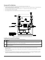
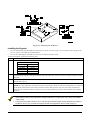
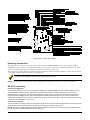
Guidelines for Wiring a System
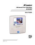
•
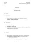
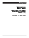
The installer must keep certain guidelines in mind while installing a system. The Vista-128FBPT/250FBPT
contains an ECP bus and a polling loop bus for connecting Fire and Burglary devices. When installing both
Commercial Fire and Burglary devices, all Fire devices must be isolated from the Burglary devices on each
bus. This is accomplished by using an ECP isolator on the ECP bus, and a V-Plex VSI on the V-Plex loop,
as shown in Figure 1-1.
•
Additionally, in Commercial Fire installations, the primary keypad must be connected to Keypad Port 2
mounted within 20 feet of the control panel, and wired in conduit.
•
Synchronization is required on devices connected to an individual alarm output. Each NAC can have its
own synchronization module in order to synchronize devices on that output, and those devices should be
located in the same visual/audible area. No synchronization is required between two outputs/individual
sync modules.
•
Notification Appliance Circuits (NAC) must be wired and isolated or Riser Conductors must be installed in
accordance with the survivability from attack by fire requirements in the National Fire Alarm Code, NFPA
72.
15
Figure 1-1: Isolating Fire Devices from Burglary Devices
16
Section 2: Partitioning
• • • • • • • • • • • • • • • • • • • • • • • • • • • • • • • • • • • • • • • • • • • • • • • • •
Theory of Partitioning
This system provides the ability to arm and disarm up to 8 different areas, as if each had its own control. These areas
are called partitions. A Partitioned system allows the user to disarm certain areas while leaving other areas armed, or
to limit access to certain areas to specific individuals. Each system user can be assigned to operate any or all partitions,
and can be given a different authority level in each.
Before anything can be assigned to those partitions, you must first determine how many partitions (1-8) are required.
Following are some facts you need to know about partitioning.
Keypads
Each keypad must be given a unique "address" and be assigned to one partition. It can also be assigned to Partition 9 if
Master keypad operation is desired. (See “Master Keypad Setup and Operation” later in this section.)
UL
In Commercial Fire installations, field 2∗18 (Log on from other partitions) must be disabled for partition 1.
Zones
Each zone must be assigned to one partition. The zones assigned to a partition will be displayed on that partition's
keypad(s).
UL
All fire zones must be assigned to partition 1 to ensure that all Fire Test modes operate correctly.
Users
Each user may be given access to one or more partitions. If a user is to operate more than one partition and would like
to arm/disarm all or some of those partitions with a single command, the user must be enabled for Global Arming for
those partitions (when entering user codes).
A user with access to more than one partition (multiple access) can "log on" to one partition from another partition's
keypad, provided that program field 2∗18: Enable GOTO is enabled for each partition he/she wants to log on to from
another.
A partition can be selected as a "common lobby" partition, and other partitions can affect this partition by causing
arming/disarming of this partition to be automated (see “Common Lobby Logic” later in this section).
Setting-Up a Partitioned System
The basic steps to setting up a partitioned system are described below. If you need more information on how to program
the options, see the Programming Guide.
1.
2.
3.
4.
5.
Determine how many partitions the system will consist of (programmed in field 2∗00).
Assign keypads to partitions (Device Programming in the #93 Menu Mode).
Assign zones to partitions (Zone Programming in the #93 Menu Mode).
Confirm zones are displayed at the keypad(s) assigned to those partitions.
Assign users to partitions.
6.
Enable the GOTO feature (program field 2∗18) for each partition a multiple-access user can log on to (alpha keypad
only).
Program partition-specific fields) (see the Programming Guide).
7.
Common Lobby Logic
When an installation consists of a partition shared by users of other partitions in a building, that shared partition may
be assigned as the "common lobby" partition for the system (program field 1∗17). An example of this might be in a
medical building where there are two doctors’ offices and a common entrance area (see example that follows
explanation).
The Common Lobby feature employs logic for automatic arming and disarming of the common lobby. Two programming
fields determine the way the common lobby will react relative to the status of other partitions. They are: 1∗18 Affects
Lobby and 1∗19 Arms Lobby.
17
1∗18
Affects Lobby (must be programmed by partition)
Setting this field to 1 for a specific partition causes that partition to affect the operation of the common lobby as follows:
a. When the first partition that affects the lobby is disarmed, the lobby is automatically disarmed.
b. The common lobby cannot be armed unless every partition selected to affect the lobby is armed.
Arms Lobby (must be programmed by partition)
1∗19
Setting this field to 1 for a specific partition causes that partition to affect the operation of the common lobby as follows:
a. The common lobby cannot be armed unless every partition selected to affect the lobby is armed.
b. Arming a partition that is programmed to arm the lobby causes the system to automatically attempt to arm the
lobby. If any faults exist in the lobby partition, or if another partition that affects the lobby is disarmed, the lobby
cannot be armed, and the message "UNABLE TO ARM LOBBY PARTITION" is displayed.
You cannot select a partition to "arm" the lobby unless it has first been selected to "affect" the lobby. Do not enable
field 1∗19 without enabling field 1∗18.
The following chart sums up how the common lobby partition will operate.
1∗18
Affects Lobby
1∗19
Arms Lobby
Disarms when
partition disarms?
Attempts to arm
when partition
arms?
Can be armed if
other partitions
disarmed?
0
0
NO
NO
YES
1
0
YES
NO
NO
1
1
YES
YES
NO
0
1
---ENTRY NOT ALLOWED---
Example
Here is an example of how the lobby would react in a typical setup.
User #1 has access to Office #1 and the Common Lobby.
User #2 has access to Office #2 and the Common Lobby.
Office #1 is set up to affect the Common Lobby, but not arm it.
Office #2 is set up to affect and arm the Common Lobby.
NOTE: In the tables below, the notations in parentheses ( ) indicate the current status of the other partition when the
user takes action.
Sequence #1:
Office 1
Office 2
Lobby Action
User #1:
Disarms
(Armed)
Disarms
User #2:
(Disarmed)
Disarms
No Change
User #1:
Arms
(Disarmed)
No change
User #2:
(Armed)
Arms
Arms
18
Sequence #2:
Office 1
Office 2
Lobby Action
User #2:
(Armed)
Disarms
Disarms
User #1:
Disarms
(Disarmed)
(No change)
User #2:
(Disarmed)
Arms
No Change
User #1:
Arms
(Armed)
No Change
Notice that in sequence #1, because Office #2 was the last to arm, the lobby also armed (Office #2 is programmed to
affect and arm the lobby). In sequence #2, the lobby could not arm when Office #2 armed, because Office #1, which
affects the lobby, was still disarmed.
When Office #1 armed, the lobby still did not arm because Office #1 was not programmed to arm the lobby. User #1
would have to arm the lobby manually. Therefore, you would want to program a partition to affect and arm the lobby if
the users of that partition are expected to be the last to leave the building.
Do not assign partition 1 as the common lobby if fire zones are being used in the system. All fire zones must be
assigned to partition 1 to ensure all Fire Test modes operate correctly.
How User Access Codes Affect the Common Lobby
Codes with Global Arming
If a code is given "global arming" when it is defined (see the SECTION 6: User Access Codes), the keypad prompts the
user to select the partitions they want to arm. Only the partitions the user has access to are displayed. This allows the
user to choose the partitions to be armed or disarmed, and so eliminates the "automatic" operation of the lobby. Keep in
mind, however, that if a user attempts to arm all, and another "affecting" partition is disarmed, the user cannot arm the
lobby, and the message "UNABLE TO ARM LOBBY PARTITION" is displayed.
Codes with Non-Global Arming
If a user arms with a non-global code, the lobby partition operation is automatic, as described by fields 1∗18 and 1∗19.
Other Methods of Arming/Disarming
Common Lobby logic remains active when arming or disarming a partition that affects and/or arms the common lobby in
one of the following manners:
•
Quick-Arm
•
Keyswitch
•
Wireless Button
•
Wireless Keypad
Arming/Disarming Remotely
If a user arms or disarms remotely (through Compass downloading software), the lobby does not automatically follow
another partition that is programmed to arm or disarm the lobby. The lobby must be armed separately, after arming all
affecting partitions first.
Auto-Arming/Disarming
If scheduling is used to automatically arm and/or disarm partitions, the common lobby partition does not automatically
follow another partition that is programmed to arm or disarm the lobby. The lobby partition must be scheduled to
arm/disarm and must be scheduled as the last partition to arm.
If you are using auto-arming, make sure that the Auto-Arm Delay and Auto-Arm Warning periods, for the lobby
partition, (fields 2∗05 and 2∗06) combined are longer than that of any other partition that affects the lobby. This
causes the lobby to arm last.
Master Keypad Setup and Operation
Although this system has eight actual partitions, it provides an extra partition strictly for the purpose of assigning
keypads as Master keypads for the system.
Assigning any keypad to Partition 9 in Device Programming in the #93 Menu Mode makes that keypad a Master keypad.
A Master keypad reflects the status of the entire system (Partitions 1-8) on its display at one time. This is useful
because it eliminates the need for a building security officer to have to log on to various partitions from one partition's
keypad to find out where an alarm has occurred.
UL
In Commercial Fire installations, field 2∗18 (Log on from other partitions) must be disabled for partition 1.
19
The following is a typical display:
SYSTEM 12345678
STATUS RRNNA TB
Possible status indications include:
A = Armed Away
S = Armed Stay
I = Armed Instant
R = Ready
B = Bypassed/Ready
F = Fire Alarm
∗ = Alarm
P = AC Power Failure
M = Armed Maximum
N = Not Ready
C = Comm Fail
T = Trouble
L = Low System Battery
To obtain more information regarding a particular partition, enter [∗] + Partition No. (e.g., [∗] + [4]). This allows viewing
only of that partition. In order to affect that partition, the user must use a code that has access to that partition. Also,
in order for a user of any partition to log on to Partition 9 to view the status of all partitions, that user must have access
to all partitions. Otherwise, access is denied.
The following is displayed for a fault condition on Zone 2 (Loading Dock Window) on Partition 1 (Warehouse) when a
user logs on from a keypad on Partition 9:
WHSE DISARMED
HIT T FOR FAULTS
Pressing [∗] causes the following display to appear at Partition 1's keypad(s):
FAULT 002 LOADING
DOCK WINDOW
Additional zone faults are displayed one at a time. To display a new partition's status, press [∗] + Partition No.
The Armed LED on a Master keypad is lit only if all partitions have been armed successfully. The Ready LED is lit only
if all partitions are "ready to arm." Neither LED is lit if only some partitions are armed and/or only some partitions are
ready.
Press [∗] + [0] or [∗] + [9] to return to the master partition. Otherwise, if no keys are pressed for 2 minutes, the system
automatically returns to the master partition
The sounder on a Master keypad reflects the sound of the most critical condition on all of the partitions. The priority of
the sounds, from most to least critical, is as follows:
1. Pulsing fire alarm sounds
2. Steady burglar alarm sounds
3. Trouble sounds (rapid beeping)
Silence the sounder by pressing any key on the Master keypad or a keypad on the partition where the condition exists.
A Master keypad uses the same panics as Partition 1. Master keypad panics are sent to Partition 1, and will activate
on Partition 1. Therefore, panics must be programmed for Partition 1.
Priority of Displays for Multi-Partition
This table shows the priority of displays if more than one of these conditions exists at the same time.
Priority
Description
Display
Priority
Description
Display
F
8
Not Ready
N
∗
9
Ready
R
1
Fire Alarm
2
All Other Alarms
3
AC Loss
P
10
Armed STAY
S
4
Comm Fail
C
11
Armed AWAY
A
5
System Low Battery
L
12
Armed INSTANT
I
6
Trouble
T
13
Armed MAXIMUM
M
7
Bypass
B
20
Section 3: Installing the Control
• • • • • • • • • • • • • • • • • • • • • • • • • • • • • • • • • • • • • • • • • • • • • • • • •
This section describes the procedures for mounting and wiring the control panel and all the peripheral devices.
NOTE: All references in this manual for number of zones, number of user codes, and the event log capacity, use the
VISTA-250FBPT’s features. See SECTION 1: General Description for the table listing the differences between the
VISTA-128FBPT and the VISTA-250FBPT control panels.
Mounting the Control Cabinet
To mount the control cabinet, perform the following steps:
Step
Action
1
Before mounting the circuit board, remove the metal knockouts for the wiring entry that you will be using.
DO NOT ATTEMPT TO REMOVE THE KNOCKOUTS AFTER THE CIRCUIT BOARD HAS BEEN
INSTALLED.
2
Using fasteners or anchors (not supplied), mount the control cabinet to a sturdy wall in a clean, dry area
that is not readily accessible to the general public. The back of the cabinet has 4 holes for this purpose.
UL
To provide certificated burglary service for UL installations, refer to the special requirements and Figure 3-2. Cabinet
Attack Resistance Considerations to follow.
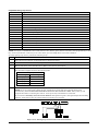
Installing the Cabinet Lock
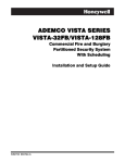
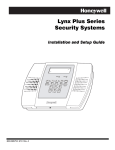
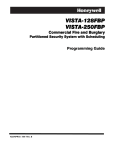
To install the lock, see Figure 3-1 and perform the following steps:
Step
Action
1
Remove cabinet door, then remove the lock knockout from the door. Insert the key into the lock.
2
Position the lock in the hole, making certain that the latch will make contact with the latch bracket when
the door is closed.
3
When correctly positioned, insert supplied lock clip on the inside of the cabinet into the slots on the lock
cylinder. Use an ADEMCO Lock No. N6277V1 and Lock Clip No. P3422-2 (supplied).
Figure 3-1: Installing the Lock
21
Mercantile Premises Listing Guidelines
•
•
•
•
•
The panel door must be super vised. M ount t he clip-on t amper swit ch (supplied) t o t he cabinet 's r ight side wall and
wir e it t o zone 6.
Assign zone 6 t o a bur glar y par t it ion. Pr ogr am it for day t r ouble/night alar m (zone t ype 5) when only one bur glar y
par t it ion is used. Pr ogr am it for 24-hr . audible alar m (zone t ype 7) when mor e t han one bur glar y par t it ion is used.
Enable field 3* 17 so t hat t he syst em r esponds t o a gr ound fault in accor dance wit h it s zone t ype r at her t han a
gr ound fault r esponse.
All wir ing bet ween t he t r ansfor mer and panel must be r un in conduit . Remaining wir es do not need t o be r un in
conduit .
All unused knock out s must be plugged using t he disc plugs and car r iage bolt s (supplied), as indicat ed in Figur e 3-2.
Fast en t he cabinet door t o t he cabinet backbox using t he 15 one-inch-long Phillips-head scr ews (supplied) aft er all
wir ing, pr ogr amming, and check out pr ocedur es have been complet ed.
Figure 3-2: Cabinet Attack Resistance Considerations
Mercantile Safe and Vault Listing Guidelines
•
•
Follow t he guidelines given above for M er cant ile Pr emises list ing.
For safe and vault installations, a shock sensor (not supplied) that is Listed for protection of sheet metal enclosures,
as well as an additional Listed tamper switch, must be installed on the cabinet backbox to protect the cabinet from
being removed from the wall. These devices must also be connected to zone 6.
22
Commercial Fire Guidelines
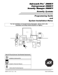
For Commercial Fire installations, the following requirements apply (See Figure 3-3).
•
System components mounted inside the cabinet must be placed so that all power-limited wiring is separated from all
non-power-limited wiring by ¼-inch (6.4mm).
•
Non-power-limited wiring that exits the control panel (i.e., transformer wiring) must be run in conduit.
•
All unused knockouts must be plugged.
•
All wiring that exits the control panel must be strain-relieved (e.g., tie-wrapped).
Figure 3-3: Commercial Fire Installation Considerations
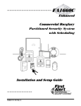
Installing the Control's Circuit Board
To install the circuit board in the cabinet, perform the following steps:
Step
Action
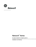
1
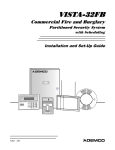
Confirm the Mounting Plate is installed securely in the cabinet (Figure 3-4, Detail A). Install the nylon
standoffs (supplied) into the top corner holes of the mounting plate (Detail B.) Insert the top of the circuit
board onto the two standoffs at the top of the mounting plate.
2
Place the board flat and secure to the mounting plate with the three accompanying screws and spacers as
shown in (Detail C.)
NOTES:
•
Make sure that the tabs on the side of the plate did not pop out during shipping and are inserted into the
appropriate slots.
•
Make sure that the mounting screws are tight. This ensures that there is a good ground connection between the PC
board and the cabinet.
•
Dress field wiring away from the microprocessor (center) section of the PC board. Use the mounting plate brackets
on the left and right sidewalls of the cabinet for anchoring field wiring using tie wraps (Figure 3-3). These steps are
important to minimize the risk of panel RF interference with television reception.
23
Figure 3-4: Mounting the PC Board
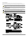
Installing the Keypads
Up to 31 addressable keypads (addresses 00-30) may be used. You may need to use an auxiliary power supply if the
1A aux. output is exceeded (for Canada 650mA).
•
Use a 2-line alpha display, 6160CR-2 (for fire only) or 6160 (for burglary only).
To wire the keypads, perform the following steps:
•
Step
Action
1
Determine wire gauge by referring to the Wire Run Length/Gauge table below.
Wire Run Length/Gauge Table
Wire Gauge
Length
#22 gauge
450 feet
#20 gauge
700 feet
#18 gauge
1100 feet
#16 gauge
1750 feet
2
Wire keypads to a single wire run or connect individual keypads to separate wire runs. The maximum wire run
length from the control to a keypad, which is homerun back to the control, must not exceed the lengths listed in
the table.
3
Run field wiring from the control to the keypads (using standard 4-conductor cable of the wire gauge
determined in step 1).
4
Connect keypad(s) to terminals 11, 12, 13, and 14 on the control board, see Figure 3-5.
NOTE: In a Fire Application and when using only one keypad, it must be connected to Keypad Port 2, and must
be mounted within 20 feet of the cabinet wired in conduit. The keypad on Port 2 is electrically isolated from
those on Port 1 and will continue to function even if wiring problems prevent the other keypads from working
properly.
•
•
The length of all wire runs combined, regardless of the wire gauge, must not exceed 2000 feet when unshielded
quad conductor cable is used (1000 feet if unshielded cable is run in conduit, which acts a shield, or if shielded
cable is used).
If more than one keypad is wired to one run, then the above maximum lengths must be divided by the number of
keypads on the run (e.g., the maximum length is 225 feet if two keypads are wired on a #22 gauge run).
24
Figure 3-5: Keypad Connections to Control Panel
Commercial Fire Requirements
For commercial fire installations, the primary fire keypad must be installed on panel Keypad Port 2 and mounted within
20 feet of the control panel. External wiring must be run in conduit.
Additionally, you can install supplemental fire keypads and devices on ECP Port 1, using an ECP Isolator to separate all
fire wiring from all burglary wiring (see Figure 3-6).
Figure 3-6. ECP Isolator Wiring
Addressing the Keypads
The keypads will not operate until they are physically addressed and enabled in the system's Device Programming
in the #93 Menu Mode.
Set each keypad for an individual address (00-30) according to the keypad's instructions. Set an alpha keypad for
address 00 and other keypads for higher addresses (00 and 01 are enabled in the system's default program). Any
keypads set for address 02 and above will appear blank until they are enabled in the system's program. Each keypad
must be set for a different address.
25
• Do not set any keypads to address 31 (nonaddressable mode). They will interfere with other keypads (as well as
other devices) connected to the keypad terminals.
• If an “OPEN CIRCUIT” message is present on a keypad, data from the control is not reaching the keypad. Please
check your wiring.
Supplementary Power Supply for Additional Keypads
When the control’s auxiliary power load for all devices exceeds 1A, you can power additional keypads from a regulated
12VDC power supply. Use a UL Listed, battery-backed supply for UL installations. For fire applications, the power
supply must be UL1481 Listed.
Connect the additional keypads as shown in Figure 3-7, using the keypad wire colors shown. Be sure to observe the
current ratings for the power supply used.
UL
For UL commercial fire and burglary installations, no more than one wire per terminal may be connected.
Use only 14-22AWG wire.
• Make connections directly to the screw terminals as shown in Figure 3-7.
• Be sure to connect the negative (–) terminal on the power supply unit to terminal 7 (–) on the control.
Figure 3-7. Using a Supplementary Power Supply
Installing External Sounders
The VISTA-128FBPT/VISTA-250FBPT provides two Notification Appliance Circuits for operating fire and burglary
alarm notification appliances. Each circuit is rated as Special Application or Regulated NAC for Fire and 10VDC –
14VDC, 1.7A max. power-limited for Burglary.
NOTE: Bell 1 should only be used for Burg and Bell 2 for Fire.
NOTE: The total alarm current drawn from Auxiliary Power 1, Auxiliary Power 2, polling loop, Bell 1, and Bell 2 cannot
exceed 2.3A (for Canada 1.95A) for battery-independent operation.
The outputs have the following options:
•
Selectable to activate by individual zone assignments
26
•
•
•
Selectable for confirmation of arming ding.
Selectable to chime when entry/exit or perimeter zones are faulted.
Selectable for no timeout or timeout of 2-30 minutes.
You may use a Commercial Fire Listed 24VDC Power Supply to convert one or both VISTA-128FBPT/VISTA250FBPT 12VDC, 1.7A style-Y supervised Special Application Notification Appliance Circuits to 24V, style-Y
supervised, Special Application Notification Appliance Circuits.
UL
•
•
Burglary Notification Appliance Circuits must be programmed for a timeout of 16 minutes or longer.
Commercial fire alarm systems require Notification Appliance Circuits to be supervised.
Notification Appliance Circuit Supervision
The VISTA-128FBPT/VISTA-250FBPT monitors the Notification Appliance Circuits wiring for open and short circuit
faults while the output is inactive. The system provides a trouble indication (Zone 970 Bell 1; 971 Bell 2) when an open
occurs. When a short occurs between the Bell (+) and Bell (-) terminal wiring, or between the Bell (+) terminal wiring
and earth ground the system provides a trouble indication (972 Earth Ground).
The VISTA-128FBPT/VISTA-250FBPT indicates the trouble condition regardless of whether the system is armed or
disarmed. The zone displays on the keypads, reports to the event log, and transmits to the central station (if
programmed) on Partition 1. The trouble is cleared from the display by entering the user code + OFF.
UL
ULC
Use only UL Listed sounding devices for UL installations.
In Commercial Fire installations, the 4204CF cannot be used to drive sounders in the same audible area as
sounders connected to the alarm outputs of the control panel.
For ULC fire installations, alarm indicating devices must not be connected to the fire transmitter. These
devices must be connected to the Fire Alarm Control Panel.
Synchronization Requirements for Commercial Fire
Notification Appliance Circuit outputs must be wired to a Sync Module if more than one device is used. Follow
instructions provided with Sync Module. Be sure to use the compatible Sync Module for the Alarm Indicating Device
selected.
MANUFACTURER
SYNC MODULE MODEL NUMBER
GENTEX
AVSM
SYSTEM SENSOR
MDL
WHEELOCK
DSM
UL
All visual notification appliances within the same physical area must be synchronized.
The bell outputs are listed as Special Application Notification Appliance Circuits.
Compatible Alarm Indicating Devices
ALARM INDICATING DEVICE TYPE
UL listed Grade A Bell in Housing
RX7 UL Indoor Sounder, 12V
Horn Strobe 2w
Horn Strobe 2w
Horn Strobe 4w
Horn Strobe 4w
Chime, 12/24V, Selectable Tone & Volume, Red
Chime, 12/24V, Selectable Tone & Volume, White
Chime/Strobe, 12/24V, Selectable Candela, Tone & Volume, Red
Chime/Strobe, 12/24V, Selectable Candela, Tone & Volume, White
Horn, 12/24V, Red
Horn, 12/24V, White
Horn, 12/24V, Outdoor, Red
2-Wire Wall Mount Horn/Strobe, 12/24V, Standard Candela, Red
MANUFACTURER
Honeywell/ADEMCO
ADT
GENTEX
GENTEX
GENTEX
GENTEX
SYSTEM SENSOR
SYSTEM SENSOR
SYSTEM SENSOR
SYSTEM SENSOR
SYSTEM SENSOR
SYSTEM SENSOR
SYSTEM SENSOR
SYSTEM SENSOR
27
MODEL #
AB12M
875936B
GEC3-12, GES3-12, GEH-12
GEC3-12, GES3-12, GEH-12
GEC3-12, GES3-12, GEH-12
GEC3-12, GES3-12, GEH-12
CHR
CHW
CHSR
CHSW
HR
HW
HRK
P2R
ALARM INDICATING DEVICE TYPE
2-Wire Wall Mount Horn/Strobe, 12/24V, High Candela, Red
2-Wire Wall Mount Horn/Strobe, 12/24V, Standard Candela, Red, Outdoor
2-Wire Wall Mount Horn/Strobe, 12/24V, High Candela, Red, Outdoor
2-Wire Wall Mount Horn/Strobe, 12/24V, Standard Candela, White
2-Wire Wall Mount Horn/Strobe, 12/24V, High Candela, White
4-Wire Wall Mount Horn/Strobe, 12/24V, Standard Candela, Red
4-Wire Wall Mount Horn/Strobe, 12/24V, High Candela, Red
4-Wire Wall Mount Horn/Strobe, 12/24V, Standard Candela, Red, Outdoor
4-Wire Wall Mount Horn/Strobe, 12/24V, High Candela, Red, Outdoor
4-Wire Wall Mount Horn/Strobe, 12/24V, Standard Candela, White
4-Wire Wall Mount Horn/Strobe, 12/24V, High Candela, White
2-Wire Ceiling Mount Horn/Strobe, 12/24V, Standard Candela, Red
2-Wire Ceiling Mount Horn/Strobe, 12/24V, High Candela, Red
2-Wire Ceiling Mount Horn/Strobe, 12/24V, Standard Candela, Red, Outdoor
2-Wire Ceiling Mount Horn/Strobe, 12/24V, High Candela, Red, Outdoor
2-Wire Ceiling Mount Horn/Strobe, 12/24V, Standard Candela, White
2-Wire Ceiling Mount Horn/Strobe, 12/24V, High Candela, Red
4-Wire Ceiling Mount Horn/Strobe, 12/24V, Standard Candela, Red
4-Wire Ceiling Mount Horn/Strobe, 12/24V, High Candela, Red
4-Wire Ceiling Mount Horn/Strobe, 12/24V, Standard Candela, Red, Outdoor
4-Wire Ceiling Mount Horn/Strobe, 12/24V, High Candela, Red, Outdoor
4-Wire Ceiling Mount Horn/Strobe, 12/24V, Standard Candela, White
4-Wire Ceiling Mount Horn/Strobe, 12/24V, High Candela, White
2-Wire Wall Mount Strobe, 12/24V, Standard Candela, Red
2-Wire Wall Mount Strobe, 12/24V, High Candela, Red
Wall Mount Strobe, 12/24V, Standard Candela, Red, Outdoor
Wall Mount Strobe, 12/24V, High Candela, Red, Outdoor
Wall Mount Strobe, 12/24V, Standard Candela, White
Wall Mount Strobe, 12/24V, High Candela, White
Ceiling Mount Strobe, 12/24V, Standard Candela, Red
Ceiling Mount Strobe, 12/24V, High Candela, Red
Ceiling Mount Strobe, 12/24V, Standard Candela, Red, Outdoor
Ceiling Mount Strobe, 12/24V, High Candela, Red, Outdoor
Ceiling Mount Strobe, 12/24V, Standard Candela, White
Ceiling Mount Strobe, 12/24V, High Candela, White
Horn Strobe 12V, 4W
Horn Strobe 12V, 2W
Strobe 12V
Horn Strobe 12V, 2W
Horn 12V/24V
Horn 12V
Horn 12V/24V
Bell 12V
MANUFACTURER
SYSTEM SENSOR
SYSTEM SENSOR
SYSTEM SENSOR
SYSTEM SENSOR
SYSTEM SENSOR
SYSTEM SENSOR
SYSTEM SENSOR
SYSTEM SENSOR
SYSTEM SENSOR
SYSTEM SENSOR
SYSTEM SENSOR
SYSTEM SENSOR
SYSTEM SENSOR
SYSTEM SENSOR
SYSTEM SENSOR
SYSTEM SENSOR
SYSTEM SENSOR
SYSTEM SENSOR
SYSTEM SENSOR
SYSTEM SENSOR
SYSTEM SENSOR
SYSTEM SENSOR
SYSTEM SENSOR
SYSTEM SENSOR
SYSTEM SENSOR
SYSTEM SENSOR
SYSTEM SENSOR
SYSTEM SENSOR
SYSTEM SENSOR
SYSTEM SENSOR
SYSTEM SENSOR
SYSTEM SENSOR
SYSTEM SENSOR
SYSTEM SENSOR
SYSTEM SENSOR
WHEELOCK
WHEELOCK
WHEELOCK
WHEELOCK
WHEELOCK
WHEELOCK
WHEELOCK
WHEELOCK
MODEL #
P2RH
P2RK
P2RHK
P2W
P2WH
P4R
P4RH
P4RK
P4RHK
P4W
P4WH
PC2R
PC2RH
PC2RK
PC2RHK
PC2W
PC2WH
PC4R
PC4RH
PC4RK
PC4RHK
PC4W
PC4WH
SR
SRH
SRK
SRHK
SW
SWH
SCR
SCRH
SCRK
SCRHK
SCW
SCWH
MT-121575W
AS-121575W
RSS-121575W
NS-121575W
NH-12/24
AH-12
MT-12/24, MT4-12/24
MB-G6-12, MB-G10-12
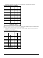
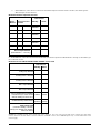
Table 3-1: BELL 1 AND BELL 2 MAXIMUM DEVICE RATING
NOTE: To use this table, the device Candela Setting and Horn Setting MUST match what is listed in
the Table.
Mfg
Gentex
Gentex
Gentex
Gentex
System Sensor
System Sensor
System Sensor
System Sensor
System Sensor
Alarm Indicating
Device Type
Horn Strobe 12V, 2w
Horn Strobe 12V, 2w
Horn Strobe 12V, 4w
Horn Strobe 12V, 4w
Horn, Strobe12/24V
Horn, Strobe12/24V
Horn, Strobe12/24V
Horn, Strobe12/24V
Horn, Strobe12/24V
Model
GEC3-12,GES3-12,GEH-12
GEC3-12,GES3-12,GEH-12
GEC3-12,GES3-12,GEH-12
GEC3-12,GES3-12,GEH-12
HR
HW
HRK
P2R
P2RH
28
Candela
Setting
15
75
15
75
15
15
Horn Setting
Mech-Temporal
Mech-Temporal
Continuous Mech
Continuous Mech
Temporal - High
Temporal - High
Max # of
Devices
6
2
6
2
38
38
38
10
10
Mfg
System Sensor
System Sensor
System Sensor
System Sensor
System Sensor
System Sensor
System Sensor
System Sensor
System Sensor
System Sensor
System Sensor
System Sensor
System Sensor
System Sensor
System Sensor
System Sensor
System Sensor
System Sensor
System Sensor
System Sensor
System Sensor
System Sensor
System Sensor
System Sensor
System Sensor
System Sensor
System Sensor
System Sensor
System Sensor
System Sensor
System Sensor
System Sensor
System Sensor
System Sensor
Wheelock
Wheelock
Wheelock
Wheelock
Wheelock
Wheelock
Wheelock
Wheelock
Bell
Alarm Indicating
Device Type
Horn, Strobe12/24V
Horn, Strobe12/24V
Horn, Strobe12/24V
Horn, Strobe12/24V
Horn, Strobe12/24V
Horn, Strobe12/24V
Horn, Strobe12/24V
Horn, Strobe12/24V
Horn, Strobe12/24V
Horn, Strobe12/24V
Horn, Strobe12/24V
Horn, Strobe12/24V
Horn, Strobe12/24V
Horn, Strobe12/24V
Horn, Strobe12/24V
Horn, Strobe12/24V
Horn, Strobe12/24V
Horn, Strobe12/24V
Horn, Strobe12/24V
Horn, Strobe12/24V
Horn, Strobe12/24V
Horn, Strobe12/24V
Strobe12/24V
Strobe12/24V
Strobe12/24V
Strobe12/24V
Strobe12/24V
Strobe12/24V
Strobe12/24V
Strobe12/24V
Strobe12/24V
Strobe12/24V
Strobe12/24V
Strobe12/24V
Horn Strobe 12V, 4W
Horn Strobe 12V, 2W
Strobe 12V
Horn Strobe 12V, 2W
Horn 12V/24V
Horn 12V
Horn 12V/24V
Bell 12V
Bell 12V
Model
P2RK
P2RHK
P2W
P2WH
P4R
P4RH
P4RK
P4RHK
P4W
P4WH
PC2R
PC2RH
PC2RK
PC2RHK
PC2W
PC2WH
PC4R
PC4RH
PC4RK
PC4RHK
PC4W
PC4WH
SR
SRH
SRK
SRHK
SW
SWH
SCR
SCRH
SCRK
SCRHK
SCW
SCWH
MT-121575W
AS-121575W
RSS-121575W
NS-121575W
NH-12/24
AH-12
MT-12/24,MT4-12/24
MB-G6-12,MB-G10-12
AB12M
Candela
Setting
15
15
15
15
15
15
15
15
15
15
15
15
15
15
15
15
15
15
15
15
15
15
15
15
15
15
15
15
15
15
15
15
15
15
15
15
15
15
na
na
na
na
na
Horn Setting
Temporal - High
Temporal - High
Temporal - High
Temporal - High
Temporal - High
Temporal - High
Temporal - High
Temporal - High
Temporal - High
Temporal - High
Temporal - High
Temporal - High
Temporal - High
Temporal - High
Temporal - High
Temporal - High
Temporal - High
Temporal - High
Temporal - High
Temporal - High
Temporal - High
Temporal - High
Temporal - High
Temporal - High
Temporal - High
Temporal - High
Temporal - High
Temporal - High
Temporal - High
Temporal - High
Temporal - High
Temporal - High
Temporal - High
Temporal - High
Continuous/Hi
Continuous/Hi
na
Hi
Hi
Hi
Continuous Horn
na
na
Max # of
Devices
10
10
10
10
10
10
10
10
10
10
10
10
10
10
10
10
10
10
10
10
10
10
10
10
10
10
10
10
10
10
10
10
10
10
4
6
6
7
80
9
10
9
9
Supervising the Notification Appliance Circuits
To wire the NAC using the supervision feature, perform the following:
Install a 2K EOL resistor (Model 2EOL, supplied) across the last notification appliance on each Notification Appliance
Circuit to be supervised.
Auxiliary Relay Connections
The VISTA-128FBPT/VISTA-250FBPT provides a built-in Form C relay with contacts rated at 28VAC/VDC, 2.8A. The
relay may be programmed (field 3∗61) for one of the following functions:
•
Alarm Activation
•
Trouble/Supervisory Activation
•
4-Wire Smoke Detector Reset
•
Battery Saver
Alarm Activation
(3∗61 = 1 or 4) Steady activation in response to an alarm.
If field 3∗61 = 1, the auxiliary relay remains active until Aux. Relay Timeout expires or until User Code + OFF is
entered. This option can be used to provide an unsupervised Notification Appliance Circuit for supplementary strobes,
sounders, etc. when wired to the Aux Power 1 or a separate power supply, see Figure 3-8.
29
If field 3∗61 = 4, the auxiliary relay remains activated until User Code + # + 67 is entered. By default, the relay is set
to activate on alarm zones 1-8 with no timeout (field 3∗61 = 1).
When field 3∗61 = 1, the auxiliary relay can be programmed to give a brief activation for confirmation of arming ding
(field 3∗57) or Chime Mode (field 3∗59).
Figure 3-8: Wiring Auxiliary Relay for Alarm Activation
Trouble/Supervisory Activation
(3∗61 = 0) Steady activation in response to any zone or system related trouble condition or to any fire supervisory
condition. The auxiliary relay remains activated until all fault conditions have been corrected and a User Code + OFF
is entered.
4-Wire Smoke Detector Reset
(3∗61 = 2) Momentary (8-second) activation in response to a second entry of a User Code + OFF sequence following a
fire alarm condition. This interrupts power to 4-wire smoke detectors connected to hardwired zones 1-8 and polling loop
zones, allowing the detectors to be reset. Power to the detectors should be wired to the auxiliary relay and to Aux. Power
1 output, see Figure 3-9.
Battery Saver
(3∗61 = 3) When this option is selected, the auxiliary relay is normally activated (e.g., N.O. and pole contacts are
connected) and de-activates 4 hours after the start of AC Loss. Using this feature, non-critical loads, such as
supplementary keypads, can be disconnected from the auxiliary power outputs, allowing a smaller capacity battery to be
used. The relay re-activates within a few seconds after the AC power restores.
Figure 3-9: Wiring Auxiliary Relay for Smoke Detector Reset
Telephone Line Connections
The VISTA-128FBPT/VISTA-250FBPT provides one main built-in dialer for communication to the central station and
one optional 5140DLM Backup Dialer, both supervised for voltage and current on the phone lines
Do not connect the system to telephone lines that require ground start service.
30
For Listed fire central station (UL864/NFPA 72) applications, use communications device 7847i alone, the main
dialer with the 7847i or use the main dialer with the 5140DLM.
For listed fire remote station (UL864/NFPA 72) applications, use the main dialer with the 5140DLM.
Telephone line supervision is required for commercial fire alarm systems.
UL
Main Dialer Connections
ULC The 5140DLM Backup Dialer cannot be used for ULC fire installations.
To connect the main dialer, refer to the Summary of Connections diagram and perform the following steps:
Step
Action
1
Connect the main dialer to the telephone company lines using the cable supplied.
2
If the dialer output is connected to telephone lines that have a telephone company MTU installed, cut the
blue jumper (W6).
Installing the 5140DLM Backup Dialer
Do not connect the main dialer and the backup dialer to the same telephone company line.
To install the 5140DLM, refer to the Summary of Connections diagram and perform the following steps:
Step
Action
1
Mount the 5140DLM to the main PC board shield.
2
Connect the backup dialer to the telephone company lines using the cable supplied.
3
Connect the backup dialer to the J3 connector on the main PC board using the ribbon cable (supplied with
the module).
4
Connect the earth ground screw on the 5140DLM to the earth ground terminal (30) on the main PC board
using 16AWG wire.
5
If the dialer output is connected to telephone lines that have a telephone company MTU installed, cut the
blue jumper on the 5140DLM PC board.
Telephone Line Supervision
If the tip/ring voltage falls below approximately 25 volts (13 volts if the blue jumper is cut) or the handset current is less
than approximately 10mA, the supervision circuits for the dialer output will indicate a fault condition. Faults on the
phone lines are displayed as zones 974 (main dialer) and 975 (backup dialer).
•
•
To prevent risk of shock, disconnect the phone lines at the telco jack before servicing the panel.
If the communicator is connected to a telephone line inside a PABX, be sure the PABX has backup power
supply that can support the PABX for 24 hours (central station usage) or 60 hours (remote station usage).
Many PABXs are not power-backed up, and connection to such a PABX results in a communication failure if
power is lost.
Zone 974 (Primary Dialer Supervision) must be enabled in order for the backup dialer (or communications
device, if used) to communicate in the event that the primary dialer fails.
If a communications device is used as the primary dialer, then its supervisory zone must be enabled (e.g. 8XX,
where XX is the device address of the communications device.
UL
The telephone line inputs have overvoltage protection in accordance with UL1459.
Reporting Formats
The system is shipped defaulted for Contact ID communication. It is the only format capable of uniquely
reporting all 250 zones, as well as openings and closings for all 250 users. This requires central stations to be
equipped with receivers that support the complete set of Contact ID report codes, such as the MX8000 or
7810iR-ent. If you need to update your MX8000 receiver, contact your distributor.
The system supports ADEMCO Contact ID; ADEMCO 10-Digit Contact ID and 4+2 Express formats.
31
Dialer Operation
When only the main dialer is enabled (field 3∗30 = 1, 0), the system attempts to route all messages over the main dialer
output. When both the main and backup dialers are enabled (field 3*30 = 1,1), the panel will Alternate Dialers by pairs
(make two attempts to report on the Main Dialer, then make two attempts to report on the Back Up dialer). The panel
will continue to do this to the Primary Phone number until it reaches its programmed attempts in 3∗21, then it will do
the same to the Secondary phone number. Test Report is always sent on Alternating dialers.
The communicator makes up to 8 attempts to transmit the messages to one or both telephone numbers (primary and
secondary), depending on the report routing options programmed. After the 8th attempt, the communicator hangs up and
the system displays “COMM FAIL” on the keypad. The number of dialer attempts are programmed in field 3∗21 (default
= 8; must be restricted to 3, 4, or 5 if a secondary phone number is programmed).
Wiring Burglary and Panic Devices to Zones 1-8
The maximum zone resistance is 100 ohms for zones 1, 2 and 8, and 300 ohms for all other zones (excluding the
2K EOL resistor).
To wire burglary and panic devices to zones 1-8, connect sensors/contacts to the hardwire zone terminals (15 through
27). Connect N.C. and N.O. devices as follows:
•
Connect N.C. devices in series with the high (+) side of the loop. The 2K EOL resistor must be connected in series
with the devices, following the last device.
•
Connect N.O. devices in parallel (across) the loop. The 2K EOL resistor must be connected across the loop wires
at the last device.
Using 2-Wire Smoke Detectors on Zones 1 and 2
Zone 1 and 2 can support up to 16 2-wire smoke detectors each (32 total).
The alarm current on zones 1 and 2 supports only one smoke detector in the alarmed state.
When assigned zone type 9 or 16, the second entry of a User Code + off at a keypad interrupts power to these zones to
allow detectors to be reset following an alarm.
Compatible 2-Wire Smoke Detectors
For ULC fire installations, 2-Wire Smoke Detectors must not be connected to the fire transmitter. These devices
ULC must be connected to the Fire Alarm Control Panel.
DETECTOR TYPE
MANUFACTURER
MODEL #
2-Wire Photoelectric Smoke Detector
DSC
FSA-210B
2-Wire Photoelectric Smoke Detector w/Heat Detector
DSC
FSA-210BT
2-Wire Photoelectric Smoke Detector
System Sensor
2W-B
2-Wire Photoelectric Smoke Detector w/Heat Detector
System Sensor
2WT-B
2-Wire Ionization Smoke Detector
System Sensor
1451 w/B401B base
2-Wire Photoelectric Low-Profile Smoke Detector
System Sensor
2151 w/B401 base *
Access Reversal Relay/Sync Module
System Sensor
RRS-MOD
2-Wire Photoelectric Smoke Detector
ESL
521B
2-Wire Photoelectric Smoke Detector w/Heat Detector
ESL
521BXT
2-Wire Photoelectric Smoke Detector w/Heat Detector
ESL
429AT
* This model may not be used on zones designated as Zone Type 16: Fire with Verification.
UL
These smoke detectors are UL Listed for use with the VISTA-128FBPT/VISTA-250FBPT and are the only 2wire smoke detectors that may be used.
A combination of heat detectors and smoke detectors is not permitted on a zone programmed for fire
verification.
Fire installations require the use of a synchronization module to synchronize the sounders and strobes on the
system.
32
Wiring 2-Wire Smoke Detectors to Zones 1 and 2
2K EOL resistors must be used on fire zones and must be connected across the loop wires of each zone at the
last detector.
To wire 2-wire smoke detectors to zone 1 and/or zone 2, perform the following steps:
Step
Action
1
Select 2-wire smoke detectors from the list of compatible detectors.
2
Connect 2-wire smoke detectors across zone 1 (terminals 15 and 16), and/or zone 2 (terminals 17 and 18) as
shown in Figure 3-10. Observe proper polarity when connecting the detectors.
3
Connect the EOL resistor at the last detector in the loop across the zone 1 terminals. The EOL resistor
must be connected across the loop wires at the last detector.
Figure 3-10: 2-Wire Smoke Detector on Zone 1 (for zone 2 use terminals 17 and 18)
Using 4-Wire Smoke Detectors on Zones 1-8
For ULC fire installations, 4-Wire Smoke Detectors must not be connected to the fire transmitter. These devices
ULC must be connected to the Fire Alarm Control Panel.
You may use as many 4-wire smoke detectors as can be powered from the panel's Auxiliary Power output without
exceeding the output's rating (1A (for Canada 650mA)).
Auxiliary power to 4-wire smoke detectors is not automatically reset after an alarm, and therefore must be
momentarily interrupted using the auxiliary relay.
Compatible 4-Wire Smoke Detectors
Use any UL Listed 4-wire smoke detector that is rated for 12VDC operation and that has alarm reset time not exceeding
6 seconds. Some compatible 4-wire smoke detectors are listed below.
DETECTOR TYPE
MANUFACTURER
MODEL #
4-Wire Photoelectric Smoke Detector
DSC
FSA-410B
4-Wire Photoelectric Smoke Detector w/Heat Detector
DSC
FSA-410BT
4-Wire Photoelectric Smoke Detector w/Sounder & Heat Detector
DSC
FSA-410BST
4-Wire Photoelectric Smoke Detector w/Aux. Relay & Heat Detector
DSC
FSA-410BRT
4-Wire Photoelectric Smoke w/Aux. Relay, Sounder & Heat Detector
DSC
FSA-410BRST
End of Line Power Supervision Relay for FSA-410 Series Smoke Detectors
DSC
RM-2
Polarity reversal module for FSA-410 series Smoke Detectors
DSC
PRM-4WC
4-Wire Photoelectric Smoke Detector
System Sensor
4W-B
4-Wire Photoelectric Smoke Detector w/Heat Detector
System Sensor
4WT-B
4-Wire Photoelectric Smoke Detector w/Sounder & Heat Detector
System Sensor
4WTA-B
4-Wire Photoelectric Smoke Detector w/Aux. Relay & Heat Detector
System Sensor
4WTR-B
4-Wire Photoelectric Smoke Detector w/Aux. Relay, Sounder & Heat Detector
System Sensor
4WTAR-B
4-Wire Photoelectric Smoke Detector w/Aux. Relay, Sounder & Isolated Heat Detector
System Sensor
4WITAR-B
4-Wire Photoelectric Air Duct Smoke Detector, Extended Air Speed Range
System Sensor
DH100ACDCLP
4-Wire Ionization Air Duct Smoke Detector
System Sensor
DH100ACDCI
33
Wiring 4-Wire Smoke Detectors
UL
Power to 4-wire smoke detectors must be supervised with an EOL device (use a System Sensor EOLR-1 EOL relay
module connected as shown in Figure 3-11).
A combination of heat detectors and smoke detectors is not permitted on a zone programmed for fire verification.
Fire installations require the use of a synchronization module to synchronize the sounders and strobes on the
system.
To wire 4-wire smoke detectors to zones 1-8 or polling loop expansion module zones, perform the following steps:
Step
Action
1
Select 4-wire smoke detectors (see list of compatible detectors shown previously in this section).
2
Connect detectors (including heat detectors, if used) across terminals of the zone selected. All detectors must
be wired in parallel. See Figure 3-11.
3
Connect the EOLR at the last detector in the loop across the zone’s terminals. You must connect the
EOLR across the loop wires at the last detector.
Figure 3-11: 4-Wire Smoke Detectors
Zone 6 Tamper Configuration
Zone 6 may be used as a tamper loop for the VISTA-128FBPT/VISTA-250FBPT Cabinet Door Tamper Switch.
Assign zone 6 to a burglary partition. Program it for day trouble/night alarm (zone type 5) when only one burglary
partition is used. Program it for 24-hr. audible alarm (zone type 7) when more than one burglary partition is used.
Enable the Zone 6 Alternate Tamper Function (program field 3∗17).
Tamper Supervision for the Hardwired Zones
The system can be programmed to monitor for either an open condition or a short condition of a tamper switch on zones
1-8. End-of-line supervision is required for this option.
Wiring a Tamper Switch to Zones 1-8
The wiring of the tamper switch depends on whether the tamper switch and the sensor are normally open or normally
closed.
•
If you are using a normally closed sensor, the tamper switch must be normally open. Refer to Figure 3-12 for
the wiring configuration.
•
If you are using a normally open sensor, the tamper switch must be normally closed. Refer to Figure 3-13 for
the wiring configuration.
To wire a tamper switch on a hardwired zone, connect the EOL resistor at the last detector in the loop across the zone’s
terminals. You must connect the EOL resistor at the last detector for proper operation of the tamper
supervision.
NOTE: For the normally closed sensor, program the zone for trouble on short. For the normally open sensor,
program the zone for trouble on open.
NOTE: For zones with a response type of 9 or 16 (Fire), the tamper selection must be “0” none.
34
Figure 3-12: Wiring a Normally Closed Sensor Loop for Tamper Supervision
Figure 3-13: Wiring a Normally Open Sensor Loop for Tamper Supervision
Installing V-Plex Devices
The polling loop provides both power and data to the V-Plex devices, and is constantly monitoring the status of all zones
enabled on the loop. The maximum current draw of all devices on the polling loop cannot total more than 128mA (unless
the system uses a 4297 Polling Loop Extender Module).
Devices that can be programmed via either DIP switches or the built-in unique serial number must be set for serial
number mode operation.
All devices on the polling loop must be wired in parallel to the [+] and [-] polling loop terminals of the control panel (28
and 29). You can wire from device to device, or have multiple branches connected directly to the control panel in a star
configuration. If a module is using optional aux power, do not connect the [ - ] polling loop terminal to the device. Use
the ground from the power source.
1. Do not run polling loop wires within 6” of AC power, telephone, or intercom wiring. The polling loop is carrying
data between the control panel and the devices, interference on this loop can cause an interruption of this
communication. The polling loop can also cause outgoing interference on the intercom or phone lines. If this
spacing cannot be achieved, shielded wire must be used. (Note that the maximum total wire length supported
is cut in half when shielded wire is used.)
2. The IS25000SN and DT7500SN can be programmed as a “Smart Contact” in Zone Programming. This
prevents those PIRs from displaying faults during the disarmed state.
3. Twisted-pair is recommended for all wire runs.
4. No more than 64mA may be drawn on any individual wire run.
UL
•
•
The 4190SN right loop must not be used, and the left loop must be EOLR-supervised.
The 4297 must be powered from the VISTA-128FBPT/VISTA-250FBPT Auxiliary Power Output.
35
Compatible Polling Loop Devices
Model Number
Type
4297
4208SN
4208SNF
269SN
5193SD
5193SDT
4101SN
4208U
4209U
4959SN
4193SN
4193SNP
4293SN
4190SN
IS2500SN
V-Plex VSI
Extender Module
8 Zone V-Plex Interface
8 Zone V-Plex Class A Interface
V-Plex Holdup Switch
Photoelectric Smoke Detector Device
Photoelectric Smoke Detector w/Heat Detector
Serial Number Single-Output Relay Module
Universal 8-Zone Expander
Universal Group Zoning Multiplex Module
Aluminum Overhead Door Contact
Serialized 2-Zone Expander
V-Plex Serialized Interface Module
Serialized 1-Zone Expander
Serialized 2-Zone Expander
V-Plex PIR
V-Plex Short Isolator
NOTE: If using the 5193SD/SDT V-Plex smoke detectors the "Smart" option must be selected in zone programming or when
they enroll unpredictable results may occur if the smoke goes into a High Sens or Low Sens condition.
To install polling loop devices, perform the following steps:
Step
Action
1
Select devices from the list of compatible devices shown previously.
2
Set the DIP switches in the device (if required). Refer to the device’s instructions for the DIP Switch Tables.
3
Mount each device in the desired location. Refer to the device’s instructions.
4
Run wires from the control panel to each device on the polling loop (see Figure 3-14). No individual wire run
may exceed the lengths shown in the following table.
Maximum Polling Loop Wire Runs
5
Wire Gauge
Max. Length
#22 gauge
650 feet
#20 gauge
950 feet
#18 gauge
1500 feet
#16 gauge
2400 feet
Wire each device to the polling loop, making sure of the correct polarity (refer to the device’s instructions).
NOTE: If you are using serial number devices, and intend to enroll each device through the keypad
automatically, wire no more than 25 of these devices to the control at a time. Then power up and
program them before connecting the next 25. Leave previously enrolled devices connected.
If you intend to manually enter the serial numbers through the keypad or through Compass downloading
software, all the devices may be connected before powering up to program.
Figure 3-14: Polling Loop Connections to the Control Panel
36
Polling Loop Supervision
A short on the polling loop is indicated by a trouble on zone 997 and reports as a trouble condition only.
If a device on the polling loop fails (the panel cannot "see" that device), the system displays a trouble condition for all
zones on that device. If the panel is armed when a device fails, and the zone is a burglary zone, the zone will go into
alarm.
A trouble on zone 997 prevents a partition from being armed, unless all polling loop zones on that partition are
bypassed.
Using the 4297 Polling Loop Extender
The 4297 Polling Loop Extender may be used to provide additional polling loop current, to extend the polling loop wire
run length, and/or to provide individual electrically isolated polling loops. Refer to Figures 3-15 and 3-16, to follow.
DO NOT use the 4197 Polling Loop Extender module with the VISTA-128FBPT/VISTA-250FBPT.
Be sure to include the total current drawn on the polling loop when figuring the total auxiliary load on the panel’s
power supply.
Figure 3-15: Polling Loop Connections Using One 4297 Extender Module
Figure 3-16: Polling Loop Connections Using Multiple Extender Modules
NOTE: The input loop limits stated in Figure 3-15 apply to Figure 3-16 as well.
37
Wireless Zone Expansion
The 5881ENHC RF Receiver, 5869 Holdup Switch Transmitter and 5817CB Wireless Commercial Household
Transmitter are listed for UL Commercial Burglary applications. All other RF receivers and transmitters are not
listed for UL Commercial Burglary applications.
UL
ULC
Wireless devices cannot be used for ULC Installations.
The following table lists the receivers that may be used and the number of zones they support.
5800 Series Receivers
Receiver
5881ENHC
5883H
Zones
up to 250
up to 250
RF System Operation and Supervision
The 5800 RF system operation has the following characteristics:
•
The receiver responds to a frequency of 345MHz.
•
The receiver has a nominal range of 200 feet.
•
Supervised transmitters send a supervisory signal every 70-90 minutes.
•
Zones 988 and 990 are used to supervise the RF reception of receivers 2 and 1, respectively. The reception is
supervised for the following two conditions:
1.
2.
UL
•
•
•
•
•
The receiver goes “deaf” (doesn’t hear from any transmitter) within a programmed interval of time (defined by
program field 1∗30).
Proper RF reception is impeded (i.e., jamming or other RF interference). The control checks for this condition
every 20 seconds.
st
nd
A response type 19 (24-Hour Trouble) must be programmed for zones 990 (1 receiver) and 988 (2 receiver) for
UL installations.
The 5881ENHC receiver contains front and back tampers that permit its use in commercial burglary installations.
You may only mount the 5881ENHC its own plastic housing. Otherwise, the receiver constantly reports a tamper
condition.
The control checks the receiver connections about every 20 seconds. The receiver supervisory zone is 8 + 2-digit
receiver device address (for example, Device address 05 = supervisory zone 805).
NOTE: This zone must be programmed with a response type (e.g., type 19 24-Hour Trouble) before it supervises the
connection to the receiver.
Use two identical receivers to provide either a greater area of coverage or redundant protection. They must be set for
different addresses.
Any zone from 1 to 250 can be used as a 5800 Series wireless zone, with the exception of zone 64 (reserved for a
wireless keypad).
RF System Installation Advisories
•
Place the receiver in a high, centrally located area. Do not place it on or near metal objects. This will decrease the
range and/or block transmissions.
•
Install the RF receiver at least 10 feet from the control panel or any keypads, to avoid interference from the
microprocessors in these units.
•
If dual receivers are used:
a. Both must be at least 10 feet from each other, as well as from the control panel and remote keypads.
b. Each receiver must be set to a different device address. The receiver set to the lower address is considered the
1st RF receiver for supervisory purposes.
c. The House IDs must be the same.
d. Using two receivers does not increase the number of transmitters the system can support (249 zones using the
5881ENHC).
Installation and Setup of the 5881ENHC RF Receiver
Take note of the address you select for the RF receiver, as this address must be enabled in the system’s Device
Programming in the #93 Menu Mode.
38
To install the 5881ENHC RF receiver, perform the following steps:
Step
Action
1
Mount the receiver, following the advisories stated previously.
NOTE: Must be mounted in a 5800Box Enclosure.
2
Set the DIP switches in the receiver for the address (01-07). See Figure 3-18.
Make sure the address setting is not being used by another device (keypad, relay module, etc.).
3
If installing a 5881ENHC, install a flat-head screw (supplied) in the case tamper tab as shown in Figure 317. When the receiver is pried from the wall, the tamper tab will break off and remain on the wall. This will
activate a tamper switch in the receiver and cause generation of a tamper signal. Note that this signal will
also be generated when the receiver’s front cover is removed.
4
Connect the receiver’s wire harness to the keypad terminals (11, 12, 13 and 14). Plug the connector at the
other end of the harness into the receiver.
5
Refer to the Installation Instructions provided with the receiver for installations regarding antenna
mounting, etc.
Figure 3-17: Installing the 5881ENHC with Tamper Protection
Figure 3-18: 5881ENHC RF Receiver (cover removed)
39
5800 Series Transmitter Setup
•
Transmitters have built-in serial numbers that must be enrolled in the system using the #93 Menu Mode
Programming, or via the downloader.
• Some transmitters can support more than one “zone” (loops or inputs) (e.g., 5817CB). Each loop must be assigned a
different zone number.
Transmitter Supervision
Supervised RF transmitters send a check-in signal to the receiver at 70–90 minute intervals. If at least one check-in is
not received from each supervised transmitter within a programmed period (field 1∗31), the “missing” transmitter
number(s) and “CHECK” or “TRBL” are displayed.
Some transmitters have built-in tamper protection, and annunciate a “CHECK” or “TRBL” condition if covers are
removed.
If a loss of supervision occurs on a transmitter programmed for Fire, it reports in Contact ID as a Fire Trouble
(373), not Loss of Supervision (381), to the central station.
Transmitter Input Types
All transmitters have one or more unique factory-assigned input (loop) codes. Transmitters can be programmed as one
of the following types:
Type
Description
RM (RF Motion)
Sends periodic check-in signals, fault and low-battery signals. The control panel automatically restores the
zone to “ready” after a few seconds. It is intended for facilities with multiple motion detectors that may fault
and restore simultaneously. The transmitter must remain within the receiver’s range.
NOTE: RF Motion may only be used on loop 1 of a door/window type transmitter.
RF (Supervised RF)
Sends periodic check-in signals, fault, restore, and low-battery signals. The transmitter must remain within
the receiver’s range.
UR (Unsupervised RF)
Sends all the signals that the RF type does, but the control does not supervise the check-in signals. The
transmitter may be carried off-premises.
BR (Unsupervised Button
RF)
These send only fault signals. They do not send low-battery signals until they are activated. The
transmitter may be carried off-premises. Not applicable in Commercial installations.
Transmitter Battery Life
Batteries in the wireless transmitters may last from 4 to 7 years, depending on the environment, usage, and the specific
wireless device being used. Factors such as humidity, high or low temperatures, as well as large swings in temperature
may all reduce the actual battery life in a given installation.
The wireless system can identify a true low battery situation, thus allowing the dealer or user of the system time to
arrange a change of battery and maintain protection for that point within the system.
Compatible 5800 Series Transmitters
Model
Product
Input Type
5800CO
5817CB
Carbon Monoxide Detector with Built-in Wireless Transmitter
Commercial Wireless Transmitter
RF
RF
5869
Holdup Switch Transmitter
RF
5806W3
Photoelectric Smoke Detector with Built-in Wireless Transmitter
RF
5808W3
Photoelectric Smoke/Heat Detector with Built-in Wireless Transmitter
RF
5809
Rate-Of-Rise Heat Detector
RF
5816
Door/Window Transmitter
RF
5820L
Door/Window Contact Transmitter
RF
5853
Wireless Glass Break Detector
RF
5870API-WH/5870API-GY
Wireless Indoor Asset Protection Device
RF
5898
Duel Tech Motion Detector
RF
40
Installing Output Devices
The VISTA-128FBPT/VISTA-250FBPT supports up to 96 outputs. Each device must be programmed as to how to act
(ACTION), when to activate (START), and when to deactivate (STOP). The 4204, 4204CF, and/or 4101SN may be used
as output devices.
NOTE: The first 32 of the 96 Output Devices may be supervised (zones 601-632). Only the relays on 4204CF
module may be supervised. If supervision is programmed for other types of Output Devices, unpredictable
results may occur.
Installing the 4204 (Burg and Aux Fire Functions) and 4204CF Relay Modules
Each 4204 module provides 4 relays with Form C (normally open and normally closed) contacts. Each 4204CF module
adds two style-Y supervised Notification Appliance Circuits to the system. For 4204CF modules, only relays 1 or 3 on
each module can be programmed.
4204 and 4204CF relays may be used to trigger auxiliary fire functions such as air handler shutdown, elevator recall,
door-holder release, sound system shutdown, etc.
The relay module will not operate until the device address you have set the DIP switches for is enabled in the
control’s Device Programming in the #93 Menu Mode.
UL
• Relays should not re-energize until the panel is fully reset.
• For Commercial Fire installations, only one notification appliance module may be used, and only one
notification appliance output (A or B) may be used on that module in a single audible/visual area.
• If the 4204CF relay is enabled for a NAC, it must follow the action of the NAC on the panel.
• Relays (aux and 4204's) cannot be used for off-premises signaling
• In Commercial Fire installations, the 4204CF cannot be used to drive sounders in the same physical area as
sounders connected to the alarm outputs of the control panel.
• Output devices are not intended for overriding automatic building and fire functions.
To install the relay modules, see Figures 3-19 and 3-20 and perform the following steps:
Step
Action
1
Set the 4204 or 4204CF’s DIP switches for a device address 01-15.
Do not use an address being used by another device (keypads, RF receivers, etc.).
Mount the 4204 and 4204CF modules per the instructions provided with them.
Connect the module’s wire harness to the control (11, 12, 13 and 14). Plug the connector on the harness to
the module.
When mounting remotely, homerun each module to the control. The table below shows the maximum wire
run lengths. Refer to the instructions provided with the 4204CF for its maximum permissible wire lengths.
2
3
Wire Gauge
#22
#20
#18
#16
Maximum Length
125 feet
200 feet
300 feet
500 feet
41
Figure 3-19: 4204 Relay Module
Figure 3-20: 4204CF Relay Module
Installing 4101SN Relay Modules
The 4101SN V-Plex Single Output Relay Module is a serial number polling loop output device. The 4101SN features the
following:
•
Form C relay contacts rated at 2A, 28VAC/VDC with contact supervision.
•
Can be used to trigger auxiliary fire functions such as air handler shutdown, elevator recall, door-holder release,
sound system shutdown, etc.
•
One class B/style B EOLR-supervised auxiliary input zone.
•
Operating power and communication with control panels via the V-Plex polling loop.
•
Electronics mounted in a small plastic case with tamper-protected cover.
42
•
•
•
If using ZONE # for the START of a polling loop output, and want the output to stop when the same zone
restores, the STOP programming must be blank.
No more than 20 polling loop outputs may be programmed for the same START or STOP condition in Output
Programming.
The position of the relay is supervised, but not the actual external contact wiring.
Connect the device to the polling loop, terminals 28 (+) and 29 (-). Be sure to observe polarity.
Installing a Remote Keyswitch
A UL-Listed remote keyswitch, such as the Honeywell 4146, can be used for remote arming/disarming of the burglary
part of the system and for silencing alarms. The keyswitch operates in only one particular partition.
ULC
Remote Arming is not a ULC Listed feature.
The keyswitch is wired across zone 7. This zone is no longer available as a protection zone. Make sure ∗15 is assigned to
part (1-9). This sets zone 7 to response type 05.
Operation
•
A momentary short arms the partition in the AWAY mode, and a short held for more than 10 seconds arms the
partition in STAY mode 1. A subsequent short disarms the partition.
•
The keyswitch LEDs indicate the partition’s status (see table that follows).
•
A momentary short silences Notification Appliance Circuits and keypad sounds, and disarms the system if it was
armed. A subsequent short clears the alarm memory indication and resets 2-wire smoke and glassbreak detectors (if
used).
•
The keyswitch can be used to silence fire alarms without disarming the burglary portion (program a “9” in field ∗15).
A momentary short silences alarm outputs only if a fire alarm is present.
UL
In Commercial Fire installations, mount the keyswitch next to the primary keypad on keypad port 2 (J4 header) and
wire in conduit within the same room as the control panel. The keypad displays the UL-required “ALARM
SILENCED” when the keyswitch is used to silence a fire alarm.
LED Indications
Green
On
Off
Off
Off
Off
Red
Off
Off
On Steady
Slow Flash
Rapid Flash
Indication
Disarmed & Ready
Disarmed & Not Ready
Armed Away
Armed Stay
Alarm Memory
The keyswitch reports as user 0, if Open/Close reporting is enabled in field ∗40.
Keyswitch Tamper Operation
For UL Commercial Burglary installations, the tamper switch must be wired to zone 6, see Figure 3-22).
Program zone 6 for Day Trouble/Night Alarm (response type 5). When the keyswitch is removed from the wall, the
tamper switch opens, causing an alarm or trouble on the zone. This also causes the control to disable keyswitch
operation until the tamper is restored and the associated partition is disarmed.
43
Wiring for the Remote Keyswitch
To install the ADEMCO 4146 keyswitch, perform the following steps:
Step
Action
1
Connect the ADEMCO 4146 to the panel as shown in Figure 3-21.
2
If you are using the tamper, make sure it is connected to a zone.
Figure 3-21: Remote Keyswitch Wiring
Installing a Remote Keypad Sounder (For Commercial Burglary use only)
An optional Amseco PAL 328N Piezo Sounder can be used to duplicate the sounds produced by the keypad’s built-in
sounder. The remote sounder will duplicate all sounds (such as alarms, trouble beeps, etc.) except for the short beeps
associated with keypad key depression. One application of this feature would be to produce chime beeps at a distant
location from the keypads.
If used, program field 3∗20 must be set to “0” and field ∗15 must be set to the desired partition number.
The remote sounder must be connected to the Output 5 on the J2 connector as shown in Figure 3-22.
Figure 3-22: Remote Keypad Sounder Wiring
44
Communicators Connected to the ECP Bus
The control can support an IP or GSM communications device (7847i, GSMV/GSMHS, or IGSMV/IGSMHS) that
connects to control panel’s keypad terminals. All messages programmed for transmission via the phone lines may also
be sent via the communications device. These messages are transmitted in Contact ID format regardless of the format
programmed for the control in fields 45 and 47.
We recommend that, if possible, you use Contact ID for the main dialer. If Contact ID is not used, certain types
of reports are not sent.
ULC
For ULC fire installations, Contact ID is the only permitted format.
Supervision
The data lines between the control and the communications device, as well as certain functions in the Communicator,
can be supervised. If communication is lost or a trouble condition occurs, both the communications device and the
control’s dialer can be programmed to send a Trouble message to the central station.
NOTE: For complete information, see the Installation Instructions that accompany the Communicator.
Operation
The VISTA-128FBPT/VISTA-250FBPT features Dynamic Signaling Delay and Dynamic Signaling Priority
message reporting when a Communicator is used. These message outputs are accessed through data fields ∗56 and ∗57,
respectively. The Dynamic Signaling feature is designed to reduce the number of redundant reports sent to the central
station.
The feature is described as follows:
Dynamic Signaling Delay (Field ∗56)
Select the time the panel should wait for acknowledgment from the first reporting destination before it attempts to send
a message to the second destination. Delays can be selected from 0 to 225 seconds, in 15-second increments.
Dynamic Signaling Priority (Field ∗57)
Select the initial reporting destination for messages, Primary Dialer (0) or Communicator (1).
The chart below provides an explanation of how the Dynamic Signaling feature functions.
If Priority (∗57) And message is…
is…
Then…
Primary Phone Acknowledged before delay expires Message is removed from queue and no message is sent to
No. ("0")
communications device.
Not acknowledged before delay
expires
Communicator
("1")
Message is sent to both the Primary Phone No. and
communications device.
Acknowledged before delay expires Message is removed from queue and no message is sent to
Primary Phone No.
Not acknowledged before delay
expires
Message is sent to both the Primary Phone No. and
communications device.
Additional communications device reporting options are defined by selecting the events for each subscriber ID in fields
∗58 and ∗59. The reporting events are Alarms, Troubles, Bypasses, Openings/Closing, System Events, and Test. Also,
within an enabled category, the specific event must be enabled for dialer reporting. If, for instance, zone 10 is enabled to
report, but zone 11 is not, zone 10 will report via the communications device, but zone 11 will not.
Messages are transmitted from the VISTA-128FBPT/VISTA-250FBPT to the communications device on a “first in/first
out” basis. If events occur at the same time, they are transmitted in order of priority. The priority from most to least
important is : Fire Alarms, Panic Alarms, Burglary Alarms, Fire Troubles, Non-Fire Troubles, Bypasses,
Openings/Closings, Test messages, and all other types of reports.
There are two subscriber IDs programmed into the communications device: primary and secondary. These correspond to
the two subscriber IDs programmed into the control for each partition. If a subscriber ID for a partition is not
programmed (disabling reports to that central station), the events enabled for the corresponding subscriber ID in the
communications device will not be transmitted.
45
If the event is to be reported to both phone numbers (dual reporting), then reporting through the communications device
will be done in an alternating sequence. The first event in the queue is transmitted to both the primary and the
secondary Communicator central stations before transmitting the second event.
If split reporting is selected for the VISTA-128FBPT/VISTA-250FBPT, then the communications device will send the
appropriate reports to the primary and secondary central stations.
Installing the Communicator
To install the communications device, perform the following steps:
Step
Action
1
Mount the communicator according to the instructions that accompany the Communicator.
2
Connect the data in/out terminals and voltage input terminals of the communicator to the control’s keypad
connection points, terminals 11, 12, 13 and 14. See Figure 3-23.
Figure 3-23: Wiring Communicator to Keypad Terminals
Trouble Messages
The following messages are displayed on the 6160/6160CR-2 when a problem exists on the communications device:
1. “LRR Battery”: The battery connected to the Communicator is low.
2. “PLL out of Lock”: The Communicator has an internal fault and cannot transmit any messages.
3. “Early Power Detect”: RF power is detected without a valid transmission.
4. “Power Unattained”: Full RF power was never attained.
5. “Frwd. Power Loss”: RF power was not sustained throughout the transmission.
6. “Antenna Fault”: A problem with the antenna has been detected.
7. “LRR CRC is bad”: The communicator’s EEPROM is corrupt (the internal CRC is bad).
NOTES:
Items 2 and 3 require factory service.
Items 4 and 5 could be the result of a bad or low battery.
If the item 6 message appears, check the antenna, connection and cable; if they are secure, factory service is required.
All these messages are displayed in conjunction with the “CHECK 8xx” message, which indicates a trouble on the
address to which the communications device is programmed in the control.
All of these events except Antenna Fault are sent to the event log and reported to the central station using Contact ID
Event Code 333 (expansion device trouble). Antenna Fault uses Event Code 357. If the tamper is tripped, it uses Event
Code 341 (expansion device tamper).
Access Control Using VistaKey
The VistaKey is a single-door access control module. When connected to the alarm system, it provides access control to
the protected premises. The VISTA-128FBPT/VISTA-250FBPT panels support up to 15 modules (15 access points).
UL
The VistaKey module contains three zones. These zones should ONLY be used for access control functions in UL
installations. THESE INPUT ZONES ARE NOT TO BE USED AS FIRE OR BURGLARY ZONES.
VistaKey Features
•
•
•
Each VistaKey communicates with the VISTA-128FBPT/VISTA-250FBPT via the V-Plex polling loop.
If local power to the VistaKey is lost, the module provides backup monitoring of the access point door via a built-in
V-Plex device that is powered solely from the polling loop. The V-Plex device is programmed in the control’s Zone
Programming. A serial number label is affixed to the VistaKey module for manual entry of its serial number.
The VistaKey supports up to 250 cardholders for the VISTA-128FBPT and 500 cardholders for the VISTA-250FBPT.
46
All configurable options for each VistaKey are accomplished via software, firmware, and nonvolatile memory, except
the access point zone number (1-15), which is set via a user-friendly, 16-position rotary switch.
The addition and removal of VistaKey modules from the system is easily accomplished via the VISTA128FBPT/VISTA-250FBPT keypad.
Each VistaKey provides one open-collector output trigger (sink 12mA @ 12VDC).
•
•
•
Mounting and Wiring the VistaKey
For detailed instructions on how to install and program the VistaKey, refer the Installation and Setup Guide that
accompanies the VistaKey-SK.
To mount and wire the VistaKey module, perform the following steps:
Step
Action
1
Mount the VistaKey, door strike or mag lock, and card reader.
2
Mount the door status monitor (DSM) and/or request-to-exit (RTE) devices.
3
Using Figure 3-24 as a reference, connect the card reader interface cable to TB3, making the +5V or +12V
connection last.
4
Connect the leads to TB1 in the following order:
a. All ground leads to terminals 2, 5, and 9.
b. The DSM, (optional) RTE, and General Purpose leads to terminals 6, 7, and 8, respectively.
c. Door strike (or mag lock) lead to terminal 10.
d. Local +12V or +24V supply lead to terminal 1.
e. Local +12V or +24V supply lead to the N/C relay terminal 11 (if a mag lock is being used), OR to the N/O
relay terminal 10 (if a door strike is being used).
5
Connect the (–) polling loop and (+) polling loop leads (from the VISTA-128FBPT/VISTA-250FBPT) to
terminals 4 and 3, respectively.
6
Set the Address Select switch to the desired access door number (1-15).
7
Repeat steps 1 through 6 for each VistaKey being installed.
Connecting the Card Reader
Lead from Reader
Lead Color
To VistaKey TB3 Terminal #
Green LED
Ground*
DATA 1 (Clock)
DATA 0 (Data)
+5VDC†
+12VDC†
Orange
Black
White
Green
Red†
Red†
1
2
3
4
6
7
* TB-3 Terminal 5 is also a ground and may be used instead of terminal 2. Terminals 2 and 5 are a common ground.
† Connect to +5VDC OR +12VDC per reader manufacturer’s specification.
47
Figure 3-24: Wiring the VistaKey
Event Log Connections
This system has the ability to record up to 1000 events using the VISTA-250FBPT or 512 events using the VISTA128FBPT of various categories in the Event Log (history log) of various categories in the Event Log (history log). Each
event is recorded with the time and date of its occurrence (if real-time clock is set).
The categories are Alarm, Supervisory/Check, Bypass, Open/Close, System and Test conditions. The log may be viewed
on an alpha keypad, the AUI or printed on a serial printer.
You must use the RS232 connection for log events and home control.
NOTE: If you are using a serial printer, it must configured with 7 data bits, even parity, 1 stop bit, 9600 baud
RS-232 Connectivity
Serial Port Configuration
The enhanced ser ial por t on t he Vist a Tur bo Ser ies oper at es at a speed of 9600bps. Ear lier Vist a ser ies panels used a
speed of 1200bps. (Please note t hat 1200bps opt ion has been delet ed and is no longer suppor t ed on Vist a Tur bo.)
Depending on your applicat ion, you may need t o adjust t he configur at ion of your pr int er , home aut omat ion syst em or
ext er nal soft war e package t o mat ch t he new fast er speed. Consult t he document at ion for your ext er nal har dwar e or
soft war e for dir ect ions on how t o do t his. I n some cases you may need t o cont act t he vendor of t his ext er nal har dwar e or
soft war e for an updat e pat ch or new dr iver .
Serial Port Connections
The J2 connect or is no longer used for dir ect connect , ser ial pr int er or home aut omat ion applicat ions. On all Vist a Tur bo
Ser ies panels, t her e ar e t wo met hods of connect ing t o t he ser ial (pr int er /aut omat ion) por t :
N OT E: TB4 and J13 suppor t WI N-PAK and Pr o-Wat ch, however if you want t o connect t o a pr int er you must use TB4
in or der t o get pr int er DSR super vision ("Pr int er Off L ine").
48
Using flying leads fr om t er minal block TB4 t o a 9- or 25-pin ser ial connect or .
Plugging t he VT-SERCBL cable int o header J13. This connect or t er minat es in a 9-pin ser ial connect or . To connect t his t o
a PC, you must use a st andard st r aight t hr ough ser ial cable wit h a 9-pin connect or on t he panel end and t he appr opr iat e
connect or for your PC on t he ot her end.
The TB4 met hod is int ended for per manent wir ing, e.g. when connect ing t o WI N-PAK or Pr o-Wat ch. The J13 met hod is
ideal for dir ect -connect pr ogr amming, wher e t he ser ial connect ion being made is only tempor ar y.
When connect ing via TB4, obser ve t he TB4 pin configur at ion shown on t he Summar y of Connect ions label.
Panel
9-Pin
25-Pin
TXD
3 (EBI -I PPS)
2 (EBI -I PPS)
2 (All Ot her Configur at ions)
3 (All Ot her Configur at ions)
2 (EBI -I PPS)
3 (EBI -I PPS)
3 (WI N-PAK or Pr o-Wat ch)
2 (WI N-PAK or Pr o-Wat ch)
RTS/DTR
8 (WI N-PAK or Pr o-Wat ch)
5 (WI N-PAK or Pr o-Wat ch)
CTS/DSR
4 (Pr int er Only)
20 (Pr int er Only)
GND
5 (All Configur at ions)
7 (All Configur at ions)
RXD
When connect ing via J13, use t he VT-SERCBL cable assembly. To connect t his t o a PC, you must use a standar d
st r aight t hr ough ser ial cable wit h a 9-pin connect or on t he panel end and t he appr opr iat e connect or for your PC on t he
ot her end.
I M PORT AN T : When connect ing t he VT-SERCBL cable int o header J13, t he r ed st r ip (pin 1) on t he r ibbon cable should
be t o t he left .
NOTES:
1. TB4 and J13 cannot be used simultaneously. If you are using one of these connection points to
communicate with the panel, you MUST temporarily disconnect the other wiring.
2. You cannot use WIN-PAK or Pro-Watch and the Printer at the same time.
Serial Programming Options for Automation Applications
NOTE: You cannot simultaneously use a serial printer and Home/Facility Automation.
The following group of fields must be set to use the serial port for automation applications:
∗05
Enter 1 to send System Event Messages via RS232 port
∗14
Enter 1 to enable Home/Facility Automation Control Input
1∗78 Extended Home Control Events (Enter 1 for extended)
1∗79 Home Control Event Types (Enter 1 for each event type to be enabled; 0 to disable)
1∗80 Enter 1 to improve automation performance by disabling fault/restore messages over the automation
port. If you require live mapping while the system is disarmed, you must enter 0 here.
49
Connecting the Transformer
NOTE: Upon a total power failure, the control unit will ignore and not transmit alarm supervisory information for a
stabilization period of 120 seconds following restoration of power. Within 60 seconds at the end of the stabilization
period, the control unit shall initiate the transmission of a power restoration signal code. If this report code is enabled
(see report code programming in the Programming Guide), this is the report that will be sent.
To connect the 1451 transformer to the control, perform the following steps:
Step
Action
1
Remove the front cover of the enclosure.
2
Mount the enclosure to the wall near the VISTA-128FBPT/VISTA-250FBPT control panel. The enclosure has
four mounting holes on its back surface for this purpose.
3
Run 120VAC wiring to the enclosure in conduit. A dedicated circuit must be used.
4
Use wire nuts to splice the 120VAC wires to the transformer’s white and black primary leads.
5
Connect the earth ground post on the back of the enclosure to a good earth ground.
6
Run 16AWG wire in conduit from the enclosure to the control panel.
7
Use wire nuts to splice the transformer blue 18VAC secondary leads to the 16AWG wire. Connect the 16AWG
wire at the control panel to terminals 1 and 2.
8
Replace the front cover of the enclosure and fasten it with the screws supplied.
•
•
Use wires having insulation rated for at least 90°C operation and suitable for non-power limited applications.
Use care to keep 18VAC wiring separated from all other wiring inside the control panel’s enclosure. This must
be done by running non-power-limited 18VAC wiring into the control panel’s enclosure via one of the knockouts
on the left-hand side, and then tie-wrapping these wires to the tie-wrap loops located near the knockout.
Earth Ground Connections
In order for the lightning transient protective devices in this product to be effective, the designated earth ground
terminal (terminal 30) must be terminated in a good earth ground. Recommended wire gauge for the ground connection
is #16 AWG, run no farther than 30 feet.
The panel requires the earth ground connection for its lightning transient protection devices and in order to detect
Ground Fault conditions.
To connect the earth ground, perform the following steps:
Step
Action
1
Connect the earth ground post inside the 1451 enclosure to a good earth ground (use grounding methods
specified in the National Electric Code).
Use a green nut (supplied) to secure the wire to the ground post. The ground wire should be the only wire
under this nut.
Run a 16AWG wire from the ground post to the panel’s earth ground terminal (30). Use a second green nut
(supplied) to secure this wire to the ground post.
This connection avoids ground loops that may occur when the 1451 and panel are connected to different earth
ground systems.
2
3
Determining the Control’s Power Supply Load
In the event of an AC power loss the VISTA-128FBPT/VISTA-250FBPT and the Commercial Fire Listed 24VDC Power
Supply must be supported by backup, rechargeable batteries. When the system is used without a Commercial Fire
Listed 24VDC Power Supply, a 12VDC, 12AH to 34.4AH battery must be connected the control panel.
ULC
For ULC Commercial Fire Installations, only the 34.4AH (2 x 17.2AH) batteries have been evaluated.
For ULC Commercial Fire Installations, the batteries’ capacity must be sized for 24-hour Standby followed by a
30 minute Alarm.
If a Commercial Fire Listed 24VDC Power Supply is used, refer to its Installation Instructions for the appropriate
backup battery requirements.
50
The battery’s capacity must be sized to provide 24 hours (central station fire) followed by 5 minutes (fire only) or 15
minutes (fire and burglary) alarm time. Use only sealed lead-acid batteries with a minimum charging current handling
capacity of 1.8A.
Use the worksheets that follow to calculate the total current for Auxiliary Power 1, Auxiliary Power 2, Bell 1, Bell 2,
Polling Loop and the total current load of the control panel. In each worksheet, multiply each device’s standby and/or
alarm current by the number of units used.
Then, if you are using a Commercial Fire Listed 24VDC Power Supply, calculate the Total 24VDC Power Supply Load
using the Power Supply’s instructions, to determine the required capacity of the backup batteries that must be connected
If you are NOT using a Commercial Fire Listed 24VDC Power Supply, fill out the Battery Capacity Calculation
Worksheet, following the other worksheets below, to determine the required capacity for the backup battery. Select a
battery from the Battery Selection Table (found later in this section) that have a capacity greater than or equal to the
calculated capacity.
Battery Capacity must be able to satisfy the Standby and Alarm periods in the chart below dependant on Control Panel
usage.
Control Panel Use
Standby Period
Alarm Period
Battery Capacity*
Residential Burg
4 hours
4 minutes
Commercial Burg
4 hours
15 minutes
Commercial Burg – Bank Safe and Vault
72 hours
15 minutes
Commercial/Residential Fire
24 hours
5 minutes
Canadian Commercial Fire
24 hours
30 minutes
Proprietary Burg Central Station Receiver 24 hours
--* Determine the required capacity for the backup battery by using the Battery Capacity Calculation Worksheet following the
other worksheets below if using non-Commercial Fire Listed Power Supply, or use the instructions included with the power
supply if using a Commercial Fire Listed Power Supply.
51
1.
In Worksheet 1, enter devices used on the polling loop. Calculate total current draw on the polling loop.
Worksheet 1: Total Polling Loop Current Draw
Polling Loop Device
Current
# of Units
Total
Polling Loop Subtotal
(terminals 28 & 29 – 128mA) S
S The total current cannot exceed 128mA. If total load exceeds 128mA, then a 4297 Loop Extender Module can be used. This module is
powered from the panel’s auxiliary power, and provides a separate polling loop output, which can support an additional 128mA load.
Note that the total number of points connected to the panel cannot exceed 119.
2.
In Worksheet 2, enter devices used on Auxiliary Power 1. Calculate standby and alarm currents, then add to get
Auxiliary Power 1 current subtotal.
Worksheet 2: Auxiliary Power 1 Current Load
Total Current
Device
Model #
Device Current X
# of Units
Standby
Auxiliary Power 1 Subtotal 1A max.
(terminals 10 & 11) (for Canada
650mA)
Alarm
1.7A max.
52
3.
In Worksheet 3, enter devices used on Auxiliary Power 2. Calculate standby and alarm currents, then add to
get Auxiliary Power 2 current subtotal.
Worksheet 3: Auxiliary Power 2 Current Load
Total Current
Device
Model #
Device Current X
# of Units
Auxiliary Power 2 Subtotal
(pin 5 on keypad port 2)
Standby
Alarm
400mA max.
1.7A max.
4.
In Worksheet 4, enter devices connected to the Bell 1 Output. Calculate alarm current then add to get the Bell
1 Output current subtotal.
Worksheet 4: Bell 1 Output Current Load
Total Current
Device
Model #
Device Current X
# of Units
Standby
Alarm
XXXXXX
XXXXXX
XXXXXX
XXXXXX
XXXXXX
XXXXXX
XXXXXX
Bell 1 Output Subtotal
(terminals 3 & 4 – 1.7A max.)
53
5.
In Worksheet 5, enter devices connected to the Bell 2 Output. Calculate alarm currents, then add to get the
Bell 2 Output current subtotal.
Worksheet 5: Bell 2 Output Current Load
Total Current
Device
Model #
Device Current X
# of Units
Standby
Alarm
XXXXXX
XXXXXX
XXXXXX
XXXXXX
XXXXXX
XXXXXX
Bell 2 Output Subtotal
(terminals 5 & 6 – 1.7A max.)
6. In Worksheet 6, enter the total calculated subtotals of all listed outputs from Worksheets 1 through 5, then add to get
the combined current.
Worksheet 6: Total VISTA-128FBPT/VISTA-250FBPT Current Load
Total Current
Standby
Alarm
330mA
470mA
5mA
(inactive)
15mA
(active)
Polling Loop Subtotal
Auxiliary Power 1 Subtotal
Auxiliary Power 2 Subtotal
Bell 1 Output Subtotal
Bell 2 Output Subtotal
VISTA-128FBPT/VISTA-250FBPT
PCB Current (Incl. 2-wire smoke
detector loading on zones 1 & 2)
5140DLM Backup Dialer Module
Total Current Load
(1.3A max. standby; 2.6A max.
alarm) (Can: 950mA max. standby;
2.25A max. alarm)
NOTE: The 5140DLM actually draws 55mA when active. However, since the control panel PCB current includes the main dialer
current, and since the main dialer is inactive when the 5140DLM is active, the 5140DLM imposes only a 15mA added load on the
current supply.
54
The total control panel standby load must be limited to 919mA for 24-hour standby time using two 12V, 17.2AH
batteries connected the Power supply. If you are using a Commercial Fire Listed 24VDC Power Supply use the
worksheet supplied with the power supply to determine the correct battery size.
Determining the Size of the Standby Battery
For burglary installations requiring 4-hour standby time followed by 15-minutes alarm time, use a 12AH battery to
support all loads up to and including the maximum system load (e.g., 1.3A standby/2.8A alarm total control panel load).
For fire installations requiring 24-hour standby time, use the worksheet below to calculate the required battery capacity.
7.
Use Worksheet 7 to determine the required backup battery capacity and use The Battery Selection Table to
determine the battery model number. A dual battery harness is supplied that allows two batteries to be wired in
parallel for increased capacity.
Using the total calculated from Worksheet 6, calculate the battery capacity required for the installation.
Worksheet 7: Battery Capacity Calculation Worksheet
Calculated
Value
Capacity
Formula
Standby
Capacity
Total standby current X 24 hours
X 1.1 contingency factor.
Alarm
Capacity
Total alarm curr. X 0.083 (5 min)
or X 0.250 (15 min)
Total
Capacity
Add standby and alarm
capacities
Use the Battery Selection Table to select the appropriate battery for the installation.
Battery Selection Table
Capacity
Recommended Battery
Comment
4AH
Yuasa NP4-12
7AH
Yuasa NP7-12
12AH
Yuasa NP12-12
Fits in large
mercantile
cabinet only.
14AH
Yuasa NP7-12
Connect two
in parallel.
17.2AH
Yuasa NPG18-12
Fits in large
mercantile
cabinet only.
Connect the battery, referring to Figure 3-25.
The standby battery is automatically tested for 10 minutes every 4 hours, beginning 4 hours after exiting
Programming mode. In addition, entry into the Test mode initiates a battery test. The VISTA-128FBPT/VISTA250FBPT also runs a 5-second battery test every 60 seconds to check if the battery is connected.
55
Figure 3-25: Connecting the Backup Batteries
56
Section 4: Downloading
• • • • • • • • • • • • • • • • • • • • • • • • • • • • • • • • • • • • • • • • • • • • • • • • •
General Information
Downloading allows t he oper at or t o r emot ely access, pr ogr am, and cont r ol t he secur it y syst em over nor mal t elephone
lines, I P, or GSM Communicat or s. Anyt hing t hat can be done dir ect ly fr om t he keypad can be done r emot ely, using
H oneywell’s COM PASS downloading soft war e. To communicat e wit h t he cont r ol panel, t he following is r equir ed.
System Attributes
Processor
Disk Space (free)
Monitor Resolution
Application
Operating System
Database Application
Microsoft Internet Explorer
Minimum
Intel, Pentium II – 256 MB RAM, Vista – 1GB RAM
1.5 GB
800 x 600
Recommended
Intel, Pentium, IV, 512 MB RAM (or above)
1.75 GB
1024 x 768
Version
Windows XP Professional (SP2 and SP3)
Windows Vista 32-bit (Home, Ultimate & Business)
Compatible with the latest version of Windows 7
MS SQL Server
5.5 and above
Phone Line Up Load/ Downloading
1. One of the following modems:
•
ADEMCO CIA
•
Hayes Smartmodem 1200 (external: level 1.2 or higher; internal: level 1.1 or higher)
•
Hayes Optima 24 + Fax 96 external
•
Hayes Optima 336
•
BizComp Intellimodem 1200 w/volume
•
BizComp Intellimodem 2400
Other brands are not compatible, even if claimed to be 100% compatible.
Internal modems must have a 4-position DIP switch. Modems with a 6-position DIP switch will not work.
1.
Compass revision 2.0.xx or above.
IP/GSM Downloading
Panels can be downloaded via the ECP bus over the following Communicators:
•
7845i-ent
•
IPGSM-DP
•
IPGSM-DPC
•
iGSMV-CN
•
iGSMHS
•
iGSMV
•
7847i
Access Security
The following four levels of protection guard the control against compromise while it is being accessed from a remote
location:
1. Security code handshake: The subscriber’s account number as well as an 8-digit ID number (known only to the
office) must be matched between the control and computer.
2. Hang-up and callback: The control panel “hangs up” and calls the computer back at the pre-programmed number
only if the security codes match.
3. Data encryption: All data that is exchanged between the computer and control is encrypted to reduce the possibility
of anyone “tapping” the line and corrupting data.
57
4.
Operator access levels: Operators may be assigned various levels of access to the downloader, each having its own
log-on code. The access levels allow the operators read/write capabilities of the customers’ account information. For
a detailed explanation of the access levels, see the downloading software User Manual.
NOTES:
•
Each time the control panel is accessed successfully, a Callback Requested report is sent to the central station, if
Opening reports are programmed.
•
When the system is downloading, the keypad displays “MODEM COMM.”
•
After each download or save an automatic time stamp is done to indicate the last download (or save) and the
operator ID number.
•
A complete hard copy of each individual account can be obtained by connecting a printer to the computer. Refer to
your computer Owner’s Manual or contact your dealer for printer recommendations.
Unattended Download (For Burglary Use Only)
Unattended download allows the control panel to communicate with the download computer without an operator at the
computer. This feature is useful on new installations.
The installer can mount the control, attach a keypad and phone line, and continue to wire the rest of the installation
while the system is automatically downloaded.
If Compass has an account already created, and the panel is defaulted; the installer enters Code #89, enters the
unattended phone number, account number, primary phone number, and then triggers the unattended call. The panel
calls and connects to Compass; then Compass does an upload, followed by a download of the existing account data (if this
option has been selected at the station – otherwise Compass will disconnect).
If Compass does not have an account already created, and the panel is defaulted; the installer enters Code #89, enters
the unattended phone number, account number, primary phone number, and then triggers the unattended call. The
panel calls and connects to Compass; then Compass does an upload, and disconnects (if this option has been selected at
the station – otherwise Compass will download the default account data). A new account “??????-FFFF” will be created.
For unattended download to work, the Receiver Group and Primary Phone number have to be entered into Compass.
The following items must be programmed for unattended download:
•
The account number (field ∗32)
•
Primary central station telephone number (field ∗33)
•
The download telephone number (field ∗35)
•
Unattended Mode (enable in field ∗54.)
NOTE: The default for field ∗54 is enabled (1).
Getting On-Line with a Control Panel
At the protected premises, the control panel must be connected to the existing telephone line (refer to the SECTION 3:
Installing the Control). No programming of the panel is required before downloading to an initial installation unless you
are performing an unattended download.
When establishing a connection between the computer and the control panel, the following occurs:
Stage
What Happens
1
The computer calls up the control panel. (The phone number for each customer must be entered into the
customer’s account file on the computer.)
2
The control panel answers the phone call at the pre-programmed ring count and executes a handshake with
the computer.
3
The computer sends a request for callback to the control, unless callback is not required.
4
The panel acknowledges the request and hangs up. During the next few seconds, the control processes the
request, making sure certain encrypted information received from the computer matches its own memory.
5
Upon a successful match, the control panel seizes the phone line and calls the computer back, unless
callback is not required. (The phone number to which the computer’s modem is connected must be
programmed into the control field ∗35.)
6
The computer answers, usually by the second ring, and executes a handshake with the panel.
7
The panel then sends other default information to the computer. If this information matches the computer’s
information, a successful link is established. The system is now “on-line” with the computer.
58
•
•
Alarms and Trouble responses and reports are disabled during actual uploading or downloading sessions. If
you are on-line, but not actively uploading or downloading, all alarms report immediately. All other reports are
delayed until you complete the session.
The keypads remain active when on-line with a control, but are inactive during actual uploading or
downloading sessions.
To download a control without programming any information, perform the following steps:
Step
Action
1
Enter the Installer Code + [#] + [5]. The panel temporarily enables a ring count of 5 and sets the Download
Callback option to “1” (callback not required).
2
From the computer, call the panel using the downloader software set to “First Communication” Mode.
The downloader establishes a session with no callback. The panel information can then be downloaded.
On-Line Control Functions
The following functions can be performed while on-line with a control panel (see field ∗37):
•
Arm the system in the AWAY Mode; disarm the system
•
Bypass a zone
•
Force the system to accept a new program download
•
Shut down communication (dialer) functions (for nonpayment of monitoring fees in an owned system)
•
Shut down all security system functions (for nonpayment for a leased system)
•
Inhibit local keypad programming (prevents takeover of your accounts)
•
Leave a message for customer
NOTE: Messages sent to the control panel from the downloader will be viewable at ALL partitions.
•
Command the system to upload a copy of its resident program to the office
•
Read: arming status, AC power status, list of faulted zones, list of bypassed zones, 1024 event log, list of zones
currently in alarm, list of zones currently in trouble, and ECP equipment list
•
Set the real-time clock
Direct-Wire Downloading
The VISTA-128FBPT/VISTA-250FBPT can be downloaded without using a modem or telephone line. The direct-wire
downloading connection is to be temporary, and is not part of the permanent installation. Direct-wire downloading is
meant as a tool for the installer during the installation process.
Telco Handoff
Telco handoff is another method of getting on-line with the downloader. The installer or customer enters the User Code
+ [#] + [1], while on the phone line with the computer’s modem phone line. The customer will get cut-off and the panel
and download computer will establish a connection.
59
60
Section 5: Setting the Real-Time Clock
• • • • • • • • • • • • • • • • • • • • • • • • • • • • • • • • • • • • • • • • • • • • • • • • •
General Information
This system provides a real-time clock, which must be set in order for the system’s event log to keep track of events by
time and date. It must also be set in order to execute scheduling programs (Time-Driven events).
Only users with Installer or Master authority level can set the clock.
Setting the Time and Date
To set the real time clock, perform the following steps:
Step
Action
1
Enter Installer or Master Code + [#] 63. Typical display shows:
TIME/DATE – THU
12:01am
01/01/09
The day of the week is automatically calculated based on the date entered. Time and date entries are made by
simply entering the appropriate hour, minute, month, day and year.
Press [∗] to move the cursor to the right of the display, to the next position.
Press [#] to move the cursor to the left of the display, to the previous position.
2
Enter the correct hour. Then press [∗] to move to the “minutes” field.
3
Enter the correct minutes. Press [∗] to move to the AM/PM position.
4
Press any key 0-9 to change AM to PM, or PM to AM. Press [∗] to move cursor to the “month” field position.
5
Enter the correct month using a 2-digit entry. Press [∗] to move cursor to the “day” field position.
6
Enter the correct day using a 2-digit entry. Press [∗] to move cursor to the “year” field position.
7
Enter the correct year.
Press [∗] to continue.
8
Press [∗] to exit the real-time clock edit mode.
61
62
Section 6: User Access Codes
• • • • • • • • • • • • • • • • • • • • • • • • • • • • • • • • • • • • • • • • • • • • • • • • •
General Information
The VISTA-128FBPT system allows a total of 150 security access codes to be allocated. The VISTA-250FBPT allows a
total of 250 security access codes to be allocated. Each security access code is identified by a user ID number.
Regardless of the number of partitions each code has access to, it occupies only one user slot in the system.
If a particular code is not used in all partitions, that user ID number cannot be used again.
The Quick Arm feature can also be programmed (partition-specific program field ∗29). The Quick Arm feature allows the
user to arm the system by pressing the [#] key instead of the security code. The security code must always be entered to
disarm the system.
A user code other than the installer code must be programmed in order for the Quick Arm feature to function.
The system is shipped with the following defaults for the user codes:
User
4-Digit Code
Alpha Descriptor
User 1 (Installer)
5140
INSTLR
User 2
1234
MASTER
User Codes and Levels of Authority
Each user of the system can be assigned a level of authority, which authorizes the user for certain system functions. A
user can have different levels of authority within different partitions
Use the “View Capabilities” keypad function (User Code + [∗] + [∗]) to view the partitions and authority levels for
which a particular user is authorized. These levels are described below.
Level 0: Installer (User 1) Code
•
•
•
•
•
Programmed in field ∗00 (default = 5-1-4-0). Installer Open/Close reporting selected in field ∗39.
Can perform all system functions (arm, disarm, bypass, etc.), but cannot disarm if armed by another code (or by
Quick Arm).
Can add, delete, or change all other codes, and can select Open/Close reports for any user.
Is the only code that can be used to enter program mode. The Installer Code can be prevented from re-entering the
Program Mode by exiting using ∗98.
Must program at least one Master Code during initial installation. Master Codes are codes intended for use by the
primary user(s) of the system.
Level 1: Master Codes
•
Can perform all normal system functions.
•
Can be used to assign up to 248 lower-level codes, which can be used by other users of the system.
•
Cannot assign anybody a level of 0 or 1.
•
May change their code.
•
Can add, delete, or change Manager or Operator Codes. Each user’s code can be individually eliminated or changed
at any time.
•
Open/Close reporting is automatically the same as that of the Master who is adding the new user.
Level 2: Manager Codes
•
Can perform all system functions (arm, disarm, bypass, etc.) programmed by Master.
•
May add, delete, or change other users of the system below this level (Manager cannot assign anybody a level of 0, 1,
or 2).
•
May change their code.
•
Open/Close reporting is automatically the same as that of the Manager who is adding the new user.
63
Levels 3-5: Operator Codes
•
Can operate a partition, but cannot add or modify any user code (see table below).
Level
3
4
5
•
Title
Operator A
Operator B
Operator C
Functions Permitted
Arm, Disarm, Bypass Burg Zones
Arm, Disarm
Arm, Disarm only if armed with same code
Operator C (sometimes known as the Babysitter Code) cannot disarm the system unless the system was armed with
that code. This code is usually assigned to persons who may need to arm and disarm the system at specific times
only (e.g., a babysitter needs to control the system only when babysitting).
Level 6: Duress Codes
•
Sends a silent alarm to a central monitoring station if the user is being forced to disarm (or arm) the system under
threat (system must be connected to a central station).
•
Assigned on a partition-by-partition basis, and can be any code or codes desired.
Duress Reporting NOTE: A non-zero report code for zone 992 (duress) must be programmed, and partition-specific
field ∗85 duress location enabled, to enable Duress reporting.
•
The Duress report-triggering logic activates on the 5th key depression (such as OFF), not the 4th key depression (last
digit of code). Duress reports are not triggered if the 5th key is a [∗], such as when you perform a GOTO or view the
capabilities of a user.
General Rules on Authority Levels and Changes
The following rules apply to users when making modifications within the system based on the user code authority levels:
•
Master Codes and all lower-level codes can be used interchangeably when performing system functions within a partition (a system
armed with a user’s temporary code can be disarmed with the Master Code or another user’s temporary code), except the Operator Level
C Code described above.
•
A user may not delete or change the user code of the SAME or HIGHER authority than that which he is assigned.
•
A user (levels 0, 1 and 2 only) may only ADD users to a LOWER authority level.
•
A user may assign other users access to only those partitions to which he himself has access.
•
A user code can be DELETED or CHANGED only from within the partition it was created in.
•
User numbers must be entered in 3 digits. Single-digit user numbers must, therefore, always be preceded by a “00” (e.g., 003, 004, 005,
etc.). Make sure the end user understands this requirement. Temporary codes are entered as 4-digit numbers.
Open/Close Reporting Note: When a user is added, the system prompts for Open/Close reporting capability only if the
installer is adding the new user. When a Master or Manager adds a new user, the new user’s Open/Close reporting is
the same as that of the Master or Manager who is adding the user. If Open/Close reports are required to be selectable by
the Master or Manager, the Installer should assign two Master or Manager user codes: one with Open/Close reporting
enabled, and one without.
Note that Open/Close reporting of Quick Arm is enabled if User 002 is enabled for Open/Close reporting, and that Quick
Arm reports as User 000. In order for Quick Arm reports to be sent for all partitions, User 002 must have authority and
Open/Close must be enabled for all partitions. If a code with access to all partitions is not desired, it is suggested that
user 002 be assigned authority level 5 in all partitions, and that the code be kept secret. Authority level 5 cannot disarm
the system unless armed by that user.
ADEMCO Contact ID format is capable of reporting Users 001-150 uniquely. If any other report format is used,
only user numbers 001 – 015 can uniquely report to the central station. Users 016 – 150 will report as User 015.
Multiple Partition Access
Each user is programmed for a primary (home) partition. A user can also be given access to operate one or more
additional partitions. Within each partition, each user may be programmed to have different levels of authority. For
example, User 003, the VP of Engineering, could be assigned to work within the Engineering Department (Partition 1) of
ABC Manufacturing. Because he needs the full capabilities in his area, he is assigned as a MASTER with Level 1
authority.
He must also be able to gain access to the manufacturing area (Partition 2) on an emergency basis. You can set this up
easily by requesting that he also be assigned to Partition 2, with a level of authority set lower, such as Level 4
(OPERATOR Level B).
64
The control automatically assigns him the same user number within Partition 2.
EXAMPLE OF MULTIPLE PARTITION ACCESS
Part 1
Part 2
User 3
User 3
Level 1
Level 4
Master
Oper B
Part 3
Part 4
Part 5
Part 6
Part 7
Part 8
In the above example, User 3 has MASTER authority in Partition 1 and OPERATOR B authority in Partition 2. His
user number is the same for both partitions. Note that if a user number is already being used in a partition, the system
will automatically assign a new user an unused number. Also notice that no access is allowed for this user into
Partitions 3 through 8. Attempts to access these partitions would be denied automatically.
Adding a Master, Manager, or Operator Code
During user code entry, normal key depressions at other keypads in a partition are ignored. However, panic key
depression causes an alarm and terminates user entry.
Enter Installer Code + [8] + new user no. (002-250) + new user’s code Or Master or Manager Code, but the code must be
a higher level of authority than the code being changed (e.g., a Manager Code can add an Operator-level Code, but
cannot add a Master or another Manager Code). Keypad prompts for the authority level for this user.
NOTE: All references to the number of user codes pertain to the VISTA-250FBPT. The VISTA-128FBPT allows only 150
user codes.
PROMPT
User Number = 003
Enter Auth. Level
EXPLANATION
Enter the level number as follows:
1 = Master
2 = Manager
3 = Operator A
4 = Operator B
5 = Operator C
6 = Duress
Keypad then prompts for Open/Close reporting option for this user.
Open/Close Rep.?
0 = NO , 1 = YES
Press 0 (NO) or 1 (YES), depending on whether or not arming/disarming by this user will trigger
Opening and Closing reports. This prompt appears only if the Installer Code is used to add a
user.
Group Bypassing?
0 = NO , 1 = YES
Enter 1 (YES) to allow this user to perform group bypasses. Enter 0 (NO) this user will not be
able to perform group bypasses.
NOTE: In addition to enabling the user for group bypassing, the user must also have access to
the partition(s) containing the zones being bypassed and have global arming capability.
Access Group?
Enter 0-8
If access schedules have been programmed, this prompt appears. Enter the user’s access
group number (1-8) if this user should have limited access to the system. Enter 0 if no access
group should be assigned.
RF Button ?
0=NO , 1=YES
If a 5800 Series button transmitter has been enabled for arming/disarming functions, and is not
assigned to a user, this prompt appears.
Press 0 (NO) or 1 (YES). Not used in Commercial Burg and Commercial Fire.
Multi-Access ?
0 = NO , 1 = YES
Press 0 (NO) if the user is to have access to this partition only. Press 1 (YES) if the user is to
have access to more than one partition. If NO, the program exits this mode. If YES, the keypad
prompts for the Global Arm option for this user.
65
PROMPT
EXPLANATION
Global Arm ?
0 = NO , 1 = YES
Press 0 (NO) or 1 (YES), depending on whether this user will be allowed to arm more than one
partition via Global Arm prompts (described in the VISTA-128FBPT/VISTA-250FBPT User
Guide).
The keypad now prompts for the user’s access to the next partition.
Part. 2 – SHOP ?
0 = NO , 1 = YES
Press 0 (NO) or 1 (YES), depending on whether this user will have access to the displayed
partition number. If NO, the keypad displays this prompt for the next partition number in
sequence.
If YES, the keypad prompts for the following:
•
User’s authority level in the displayed partition (see Authority Level prompt above).
•
Open/Close option for this user in the displayed partition (see Open/Close prompt above).
•
Global Arm option for this user in the displayed partition.
When all partitions have been displayed, the keypad will scroll through all partitions to which
access has been assigned, and will display the user number, authority level, open/close and
global arm options that were programmed for each partition to which the user was granted
access. For example:
Part. 1 A0* WHSE
User 003 Auth=3G.
Note that the “G” following the authority level indicates that the global arm feature is enabled for
this user in the displayed partition, and that the period at the end of the second line indicates
Open/Close reporting is enabled for this user in the displayed partition. The “*” indicates the
partition from which the user may be changed or deleted.
Changing a Master, Manager, or Operator Code
Enter Installer Code*+ [8] + new user no. (002-250) + new user’s code
*Or Master or Manager Code, but the code must be a higher level of authority than the code being changed (e.g. a
Manager Code can add an Operator-level Code, but cannot add a Master or another Manager Code).
NOTE: The VISTA-128FBPT allows only 150 user codes.
PROMPT
EXPLANATION
User Number = 003
NEW USER?
The system detects that the user number is already assigned, and prompts if this is a new user.
Press 0 (NO).
The system then confirms that the change is allowed based on authorization level.
Deleting a Master, Manager, or Operator Code
Enter your code*+ [8] + new user no. (002-250) + your code again
*Or Master or Manager Code, but the code must be a higher level of authority than the code being changed (e.g. a
Manager Code can add an Operator-level Code, but cannot add a Master or another Manager Code).
NOTE: The VISTA-128FBPT allows only 150 user codes.
PROMPT
EXPLANATION
OK TO DELETE 003?
0=NO
1=YES
The system prompts to confirm that you want to delete this user. Press 0 (NO) or 1 (YES).
If you answered “yes,” that user’s code is removed from all partitions to which it was assigned,
and all authorization levels and other information about that user are deleted. Note that a user
can be deleted only by a user with a higher authority level. A user cannot self delete.
A user code can be deleted only from the partition through which it was entered. If an attempt is made to
delete from another partition, the message “User [XXX] Not Deleted” is displayed.
66
Exiting the User Edit Mode
Press either [T] or [#], or don’t press any key for 10 seconds.
Bank Safe and Vault
The Bank Safe or Vaul t should be l imit ed t o i t s own par t it ion wher e only a M ast er or M anager code woul d
be all owed t o oper at e (see Sect i on 2 of t hi s M anual - Par t it i oning). I f r egular user s ar e enabled t her e i s a
way t o di sabl e t heir access (see bel ow):
1. Ent er Scheduling M ode by ent er ing I nst al ler Code + [#] + [80].
2. Sel ect Time Windows.
3. Cr eat e Time Window 01 as -6:00am-10:00am.
4. Cr eat e Time Window 02 as 9:30pm-10:00pm, ent er 00* t o exi t Time Windows.
5. Do not Quit M enu M ode, go t o O/C Schedules.
6. Ent er Vault Par t it ion #.
7. Assign Window 01 as t he OP window and Window 02 as t he Cl Window for M onday t hr u Sat ur day. Exit
Pr ogr am mode.
Vault Partition
1. Pr ogr am 2∗05 = 00, Aut o-Ar m Delay (par t i t i on-specific) Ar m at 10pm.
2. Pr ogr am 2∗06 = 00, Aut o-Ar m War ning Per i od (par t it i on-specific) N o War ni ng Per i od.
3. Pr ogr am 2∗07 = 00, Aut o-Disar m Del ay (par t i t i on-specific) Di sar m at 6am.
4. Pr ogr am 2∗08 = 1, For ce Ar m (par t it ion-specific) Enabl e.
5. Pr ogr am 2∗10 = 1, Al low Disar ming Only Dur ing Ar m/Disar m Windows (par t it ion-specific).
6. Pr ogr am 2∗11 = 0, Al low Disar m Out side Window if Alar m Occur s.
Panel wil l ar m at 10pm M onday t hr u Sat ur day wi t h no war ning and Only M ast er /M anager can di sar m
bet ween 10pm and 6am.
To al so Disabl e t he M ast er /M anager fr om Disar ming bet ween 10pm and 6am All M ast er /M anager codes will
only wor k bet ween 6am and 10pm M onday t hr u Sat ur day. They wi ll not wor k on Sunday or H ol idays.
1. Ent er pr ogr am mode I nst all er s code + #80
2. Ent er ‘Time Windows’ and Cr eat e window 03 for 6:00am-10:00pm, ent er 00 + ∗ t o exi t Time Windows
3. Do not Quit M enu M ode, go t o Access Sched.
4. Cr eat e Access Sched 01 by assigning Window 03 t o A1 M onday t hr u Sat ur day. Exit Pr ogr am mode
5. Assign all M ast er and M anager Codes t o Access Schedul e 01 when user codes ar e assigned.
Open and Cl osed window can be r emoved fr om schedule for Sat ur day t o pr event r egular user s (if t hey ar e
enabled for t hi s par t icular par t it ion) fr om being abl e t o disar m on Sat ur day, and window can be r emoved
fr om L imit Access Gr oup 1 for Sat ur day t o pr event M ast er /M anager Access on Sat ur day.
1 Ent er pr ogr am mode I nst all er s code + #80.
2. Go t o O/C Schedul es.
3. Ent er Vault Par t it ion, go t o Sat ur day and ent er 00 for OP and CL window.
4. Go t o Access Schedul es.
5. Ent er Schedul e 01, go t o Sat ur day and ent er 00 for Window A1. Exi t pr ogr am mode.
67
Cr eat e sel ect ed H olidays i n H ol iday Pr ogr amming and assign t o al l par t it i ons. H oliday window in
Open/Cl ose Schedul e r emains empt y t o pr event r egular user s (if t hey ar e enabled for t hi s par t icul ar
par t it ion) fr om being able t o di sar m on H olidays, and L imi t Access Gr oup 1 H oliday Window can r emai n
empt y t o pr event M ast er /M anager Access on H olidays.
1. Ent er pr ogr am mode I nst all er s code + #80.
2. Go t o H olidays.
3. Ent er Sel ect ed H oliday dat es.
4. Exit pr ogr am mode.
68
Section 7: Testing the System
• • • • • • • • • • • • • • • • • • • • • • • • • • • • • • • • • • • • • • • • • • • • • • • • •
Battery Test
When AC power is present, the VISTA-128FBPT/VISTA-250FBPT runs a brief battery test every 60 seconds to
determine if there is a battery connected, and runs an extended battery test every 4 hours to check on the battery’s
condition.
If the VISTA-128FBPT/VISTA-250FBPT finds that the battery voltage is low (less than approximately 11.5V), it
initiates a keypad “SYSTEM LOBAT” display and a rapid keypad beeping sound. It also sends a Low Battery report to
the central station (if programmed). The keypad is cleared by entering any security code + OFF, and a Restore report is
sent to the central station if the situation has been corrected.
Dialer Test
The VISTA-128FBPT/VISTA-250FBPT may be programmed to automatically transmit test reports to a central station at
intervals ranging from once per hour to once per 9999 hours (field ∗27).
Commercial Fire Alarms and Commercial Burglary requires the test report to be transmitted at least once every 24
hours. The system can be programmed to send the first report at any time of the day, or on any day of the week (field
∗83).
Fire Drill Test (Code + [#] + 69)
This test activates fire Notification Appliance Circuits for the purpose of conducting a fire drill or bell test. This test can
only be activated by the installer or master users from partition 1 keypads by entering the corresponding security code +
[#] + 69. The burglary portion of the system must be disarmed.
Keypads display “FIRE DRILL ACTIVE” while the test is active. The test is stopped by entering any user code + OFF.
The system continues to monitor all 24-hour type zones (fire, panic, etc.) and ends the test if any of these zone types
produce an alarm condition.
NOTE: When code + #69 fire Drill test is active, these zones if programmed will be disabled.
This test should be conducted at periodic intervals, as determined by the local authority having jurisdiction.
One-Man Fire Walk-Test (Code + [#] + 68)
This test causes the system to sound console beeps and Notification Appliance Circuit dings in response to fire zone
faults (zone type 9, 16 and 17) for the purpose of allowing proper zone operation to be checked without triggering alarms.
Note that the system will not be operational as an alarm system (i.e., cannot sense alarms) while this test is active. The
test can only be activated by the installer by entering the Installer’s Code and pressing [#] + 68 while the burglary
portion of the system is disarmed.
This test should be conducted at periodic intervals, as determined by the local authority having jurisdiction.
When testing non-latching devices, such as heat detectors, be sure to keep the device faulted until the system
responds with the keypad beep or siren sound. If the device is faulted only momentarily, the system may not
respond to the fault.
When this test is first activated, the system will display:
PROMPT
EXPLANATION
USE BELL DING?
Enter 1 (YES) to have the fire Notification Appliance Circuits associated with each point sound for 3 seconds
when a point is faulted.
Enter 0 (NO) if only keypad sounders are desired.
The next prompt will be displayed.
0=NO
1=YES
AUTO-TEST DET?
0=NO
1=YES
Enter 1 (YES) to have the system automatically test all polling loop points with a fire response type 9 or 16.
Other fire zones will have to be tested manually.
Enter 0 (NO) to test every point manually.
The next prompt will be displayed.
69
For true detector sensitivity tests, and for compliance with fire codes, you must enter 0 (NO) to this question.
PROMPT
EXPLANATION
LOG RESULTS?
Enter 1 (YES) to have the system log each point as it is tested. A list of untested points will also be logged.
Enter 0 (NO) if you do not want to log the results.
The next prompt will only be displayed if Contact ID report format has been selected.
0=NO
1=YES
C.S. TRANSMIT?
0=NO
1=YES
Enter 1 (YES) to have the results of the test sent to the central station. This report will consist of a list of
points that have been tested followed by a list of points that have not been tested.
Enter 0 (NO) if you do not want to report the results. A Walk-Test Start and Walk-Test End report will be
sent in either case (if programmed).
When the Test Mode is activated, the system will sound fire Notification Appliance Circuits (or any NAC having a nonzero response type programmed in the #93 Menu Mode) for 3 seconds. The system will also send a Start of Walk-Test
message to the central station, and will light the Ready, Power and Fire Trouble indicators and display window
segments to verify that they are working properly. The keypads will then display Fire Walk-Test in Progress and will
sound a single beep every 15 seconds while this test is active. Additionally, in this test mode RF receiver sensitivity is
reduced to 50% to ensure proper fire RF device mounting locations.
The system will build a list of all the fire zones (response types 9, 16, 17, 18) that need to be tested. These points will be
scrolled on the display. For each point, the keypad will display “UNTST XXX,” where XXX is the point number, followed
by an alpha descriptor for the point.
If the auto-test option has been selected, the control panel will attempt to automatically test all of the polling loop points
that have a zone response type of 9 or 16. For points that must be manually tested, fault and reset each fire alarm
sensor in turn.
Each action should cause keypads to beep and fire Notification Appliance Circuits to ding. The keypads will display the
zone number and the associated alpha descriptor while the zone remains faulted. The system automatically issues a
smoke detector power reset about 10 seconds after it finds a fault on one of these zones, to allow faulted detectors to be
reset.
The system will automatically perform the smoke detector reset on zones 1 and 2, if programmed for fire, and on
the auxiliary relay and any other output device (relay) that is programmed for smoke detector reset.
To end the test, enter any security code and press OFF. An End of Walk-Test message will be sent to the central station
(if programmed). Note that the test will automatically end if no faults are detected within a 1-hour time period.
Burglary Walk-Test
This test causes the system to sound keypad beeps in response to faults on zones for the purpose of allowing proper zone
operation to be checked without triggering alarms. This test can be activated by any user by entering the corresponding
security code and pressing TEST while the burglary portion of the system is disarmed. UL requires that this test be
conducted on a weekly basis.
When this test is first entered, the system activates the alarm output for 3 seconds. The system sends a Start of WalkTest message to the central station. The keypad displays “Burg Walk Test in Progress” and sounds a single beep every
15 seconds while the test remains active.
Open and close each protected door and window in turn. Each action should produce three beeps from the keypad. Walk
in front of any motion detectors. Listen for three beeps when the detector senses movement. The keypad displays the
zone number and alpha descriptor while a door or window remains open or while a detector remains activated.
To end this test, enter any security code and press OFF. An End of Walk-Test message is sent to the central station.
The system automatically exits the Test mode if there is no activity (no doors or windows are opened and
closed, no motion detectors are activated, etc.) for 60 minutes. The system beeps the keypad(s) twice every 5
seconds during the last 5 minutes as a warning that it is about to exit the Test mode and return to normal
operation.
70
Walk Testing the ‘Smart’ V-Plex Motion Detectors
Normally, in the test mode, the LED on the ‘Smart’ V-Plex Motion Detectors like the DT7500SN and IS2500SN is
disabled. In order to have the LED illuminate during the test mode, the PIR zone number must be entered into the
system’s test memory. To do this, once in the Walk Test Mode enter [3-digit zone number] + [#].
To remove a zone from the system’s test memory, enter [3-digit zone number] + [∗].
NOTES:
1 beep indicates a correct zone number entry.
2 beeps indicate an incorrect entry.
The system’s test memory capacity is 5 zones.
When the test mode is exited the system’s test memory is cleared.
Armed Burglary System Test
•
•
Alarm messages are sent to the central station during the armed tests. Notify the central station that a test will
be in progress.
A display of “COMM FAILURE” indicates a failure to communicate (no kissoff by the receiver at the central
station). If this occurs, verify that the phone line is connected, the correct report format is programmed, etc.
To perform an armed burglary test, proceed as follows:
Step
Action
1
Notify the central station that a test of the system is being performed.
2
Arm the system.
3
Fault one or more zones.
4
Silence alarm sounder(s) each time by entering the code and pressing OFF.
NOTE: The system must be rearmed after each code + off sequence.
5
Check that entry/exit delay zones provide the assigned delay times.
6
Check the keypad-initiated alarms, if programmed, by pressing the panic key pairs (∗and #, 1 and∗, and/or 3
and #).
The word ALARM and a descriptor “999” are displayed for ∗ and #. If [1] and [∗] are pressed, “995” is
displayed; if [3] and [#] are pressed, “996” is displayed.
7
If the system has been programmed for audible emergency, the keypad emits a loud, steady alarm sound.
Silence the alarm by entering the security code and pressing OFF. If the system has been programmed for
silent panic, there are no audible alarms or displays. A report is sent to the central station, however.
8
Notify the central station that all tests are finished, and verify results with them.
Testing Wireless Transmitters
Transmitter ID Sniffer Mode
Use the Transmitter Sniffer Mode to test that transmitters have all been properly programmed.
If a transmitter does not have its serial number “enrolled,” it will not turn off its zone number.
To enter the Transmitter ID Sniffer Mode, proceed as follows:
Step
Action
1
Enter Installer Code + [#] + [3]. The keypad displays all zone numbers of wireless units programmed into
the system.
2
Fault each wireless zone, causing each device to transmit.
As the system receives a signal from each of the transmitters, the zone number of that transmitter
disappears from the display.
3
Enter Installer Code + OFF to exit the Sniffer Mode.
71
Go/No Go Test Mode (For Burglary Use Only)
This mode assists in determining good mounting locations, and that the RF transmission has sufficient signal amplitude
margin for the installed system.
All partitions with wireless transmitters must be placed in the test mode for RF receiver sensitivity reduction
(50%). Otherwise, the RF receiver remains at full strength.
Make sure that all partitions are disarmed for this test.
•
•
To enter the Go/No Go Test Mode, proceed as follows:
Step
Action
1
2
Enter Installer Code + [5].
Fault each wireless transmitter, causing each device to transmit.
The keypad will beep three times if the signal is received.
3
If the keypad does not beep, reorient or move the transmitter to another location. Usually a few inches in
either direction is all that is required.
4
Enter Installer Code + OFF to exit the Go/No Go Test Mode.
Trouble Conditions
Supervisory Messages
Display
Description
SUPV +
Zone
Number
This indicates that a fire supervisory condition exists on the zone number displayed. This means that the
operation of the fire alarm system may be compromised.
Check or Trouble Messages
Display
Description
CHECK or
TRBL
(as per field
3∗00)
This indicates that a problem exists on the zone number displayed. Zone trouble may be caused by one of
the following conditions:
•
A hardwired fire zone is open (broken wire).
•
A Day/Night zone (zone type 5) is faulted.
•
A polling loop zone is not seen by the control panel.
•
A polling loop zone has been tampered (cover removed on a 4190SN).
•
•
A wireless zone has not checked in during the time programmed in field 1∗31.
A 5800 Series transmitter has been tampered (cover removed).
CHECK 6XX
XX = 01-32
This indicates a trouble on a 4204CF Supervised Notification Appliance Circuit (corresponding relay number
01-32).
CHECK 8XX
XX = 00-30
This indicates a trouble on a peripheral device (connected to the panel’s keypad terminals) of the
corresponding device address (00-30).
CHECK 9XX
XX = 70-77,
88,90,97
This indicates that a system trouble exists (RF receiver, Notification Appliance Circuit, etc.).
If the problem has been corrected, enter an OFF sequence (Security Code + OFF) twice to clear the display.
Power Failure
Display
Description
AC LOSS
POWER
LED is off
This indicates that the system is operating on battery power only. Check to see that the circuit breaker for
the branch circuit that your system’s transformer is wired to has not been accidentally turned off. Instruct
the user to call a service representative immediately if AC power cannot be restored.
72
Other System Messages
Display
Description
COMM
FAILURE
LO BAT
Indicates a failure occurred in the telephone communication portion of your system.
SYSTEM
LO BAT
HSENS
Indicates a low-battery condition exists in the wireless transmitter displayed. Pressing any key silences the
audible warning sound.
This indicates that a low-battery condition exists with the system’s backup battery.
Indicates a smoke detector with a high sensitivity level, which may cause a false alarm. The detector should
be cleaned or replaced.
LSENS
Indicates a smoke detector with a low sensitivity level. The detector may not detect a smoke condition. The
detector should be cleaned or replaced.
RCVR
SETUP
ERROR
Indicates the system has more wireless zones programmed than the RF receiver can support. If this is not
corrected, none of the zones in the system will be protected. If additional wireless zones are desired, use an
appropriate receiver.
MODEM
COMM
This indicates that the control is on-line with a remote computer.
System Off-Normal Report
If programmed, an Off-Normal report is generated instead of the periodic test report if any of the following conditions
are present at the time of the report:
•
Fire trouble on any zone (zone types 9, 16, 17, 18)
•
Fire supervisory present (zone type 18)
•
Unrestored fire alarm on any zone
•
Bypass of any fire zone
•
A fault for any supervised fire Notification Appliance Circuit
•
Bypass/disable of any supervised fire Notification Appliance Circuit
•
Telco fault of either dialer line
•
Bypass/disable of either dialer line
•
Earth ground fault
•
Bypass of earth ground supervisory zone
•
Fault on LORRA “XMIT OK” signal (if enabled)
•
LORRA trigger bypassed
•
AC failure
•
Low system battery
•
Keypad supervision fault
The Off-Normal report is sent as follows:
•
Contact ID: Code 608
•
High Speed: Channel 3 of system report used (channel 9=6)
•
Express Speed: Digits programmed in System Group #4 report codes
To the Installer
Regular maintenance and inspection (at least annually) by the installer and frequent testing by the user are vital to
continuous satisfactory operation of any alarm system.
The installer should assume the responsibility of developing and offering a regular maintenance program to the user as
well as acquainting the user with the proper operation and limitations of the alarm system and its component parts.
Recommendations must be included for a specific program of frequent testing (at least weekly) to ensure the system’s
proper operation at all times.
Turning the System over to the User
Fully explain the operation of the system to the user by going over each of its functions, as well as the User Guide
supplied.
In particular, explain the operation of each zone (entry/exit, perimeter, interior, fire, etc.). Be sure the user understands
how to operate any emergency feature(s) programmed into the system.
73
Contacting Technical Support
PLEASE, before you call Technical Support, be sure you:
•
READ THE INSTRUCTIONS!
•
Check all wiring connections.
•
Determine that the power supply and/or backup battery are supplying proper voltages.
•
Verify your programming information where applicable.
•
Verify that all keypads and devices are addressed properly.
•
Note the proper model number of this product, and the version level (if known) along with any documentation that
came with the product.
•
Note your Honeywell customer number and/or company name.
Having this information handy will make it easier for us to serve you quickly and effectively.
Technical Support: ..................................................... 1-800-645-7492 (8 a.m.-8 p.m. EST)
World Wide Web Address: ................................ http:// w w w . h o n e y we l l . c o m / s e c u r i t y
74
Regulatory Agency Statements
• • • • • • • • • • • • • • • • • • • • • • • • • • • • • • • • • • • • • • • • • • • • • • • • •
UL Installation Requirements
UL
This system may be used in installations that require UL2050 compliance.
NOTE: This Control unit is Listed to UL985 and UL1023.
The following requirements apply to UL commercial burglary installations:
1. All partitions must be owned and managed by the same person(s).
2. All partitions must be part of one building at one street address.
3. The audible alarm device(s) must be placed where it/they can be heard by all partitions.
4. The control cabinet must be protected from unauthorized access. This can be done by installing a tamper switch on the cabinet
door (supplied with VISTA-128FBPT/VISTA-250FBPT). Wire the selected device to any EOLR-supervised zone (Zone 1-8).
Program this zone for day trouble/night alarm (type 05) or 24-hour audible alarm (type 07) response. The 24-hour alarm response
must be used for multiple partitioned systems.
5. Remote downloading and auto-disarming are not UL Listed features.
UL864/NFPA Local Fire
Configure at least one Notification Appliance Circuit for supervision and wire polarized fire alarm indicators to it.
UL864/NFPA Central Station and Remote Station Fire
1.
2.
3.
4.
5.
6.
Size the backup battery for 24-hour standby time.
For central station service, you may use the 7845i-ent, 7847i, or IGSMV/IGSMHS communications device alone, the main dialer
with a communications device, or the main dialer with the 5140DLM Backup Dialer Module. For remote station service, you must
use the main dialer with the 5140DLM Backup Dialer Module.
When the main dialer is used, enable it (field 3∗30) and connect it to a telephone line. Assign a 24-hour trouble response (type 19)
to system Zone 974 to enable main dialer supervision. The control panel will activate the trouble trigger when it detects a main
dialer supervision fault.
When the backup dialer is used, install it on the control panel’s PCB shield as indicated in the Summary of Connections diagram.
Enable it (field 3∗30) and connect it to a separate telephone line. Assign a 24-hour trouble response (type 19) to system Zone 975 to
enable backup dialer supervision.
When the dialer is used, program it to send fire alarm, fire supervisory (if used), trouble, AC loss, low battery, normal dialer test,
and off-normal dialer test reports. Field ∗27 must be set to “024” maximum so that test reports are sent at least once every 24
hours.
If a secondary number is programmed, set the maximum number of dialer retries to 3, 4, or 5 in field 3∗21.
Commercial Burglary Requirements
The following requirements apply to all UL Commercial Burglary installations:
1. All partitions must be owned and managed by the same person(s).
2. All partitions must be part of one building at one street address.
3. The audible alarm device(s) must be placed where it/they can be heard by all partitions.
4. The control cabinet must be protected from unauthorized access. This can be done by installing a tamper switch on
the cabinet door (supplied). See additional requirements below.
UL
This system may be used in installations that require UL2050 compliance.
NOTE: This Control unit is Listed to UL985 and UL1023.
UL609 Local Mercantile Premises/Local Mercantile Safe & Vault
1.
2.
3.
All zones must be configured for EOLR supervision (∗41=0). If 4190SN V-Plex devices are used, set field ∗24 to “0” to enable
tamper detection.
Attach a Listed door tamper switch to protect the cabinet door. Wire the selected device to Zone 6. Program this zone for day
trouble/night alarm (type 05) or 24-hour audible alarm (type 07) response. The 24-hour alarm response must be used for multiple
partitioned systems. Enable field 3∗17 so that the system responds to a ground fault on that zone in accordance with the zone type
rather than a ground fault response.
For safe and vault installations, a shock sensor (not supplied) that is Listed for protection of sheet metal enclosures, as well as an
additional Listed tamper switch, must be installed on the cabinet backbox to protect the cabinet from being removed from the wall.
These devices must also be connected to zone 6.
(Also see Mounting the Cabinet in SECTION 3: Installing the Control).
4.
Entry delays must not exceed 45 seconds, and exit delays must not exceed 60 seconds.
75
5.
6.
All unused knockouts must be plugged (use the supplied disc plugs and carriage bolts).
Must be used with a Listed burglar alarm sounding device/housing. Depending on the application, a compatible Listed sounding
device enclosure may also be required.
UL365 Police Station Connected Burglar Alarm
Follow the instructions for UL609 local installations given above.
For Systems without Line Security:
•
You may use the control panel’s main dialer alone, or the 7845i-ent, 7847i, or IGSMV/IGSMHS Communications Device alone.
•
When using the dialer, program it to send Burglary Alarm, Low Battery and Communicator Test reports. Field ∗27 must be set to
“0024” (or less) so that test reports are sent at least once every 24 hours.
For Systems with Encrypted Line Security:
•
The dialer must be used in conjunction with an iGSMHS Communications Device.
UL365/UL609 Bank Safe and Vault Alarm System
•
•
•
•
•
•
•
•
•
Follow the instructions for UL609 local installations above and Bank/Mercantile Safe and Vault (page 3-2) sections of this manual.
Bell 1 Confirmation of Arming Ding (∗16) must be set to 1 to on (enabled) (will automatically test bell).
Entry delays or any other delays to report alarms may not exceed 45 seconds.
Models 7845i-ent, 7847i, IGSMV, and IGSMHS or other compatible Listed communicators with 200-second supervision of the
communication channel must be used. A DACT is not to be used.
Bell Timeout must be programmed for 16 minutes min.
Two 17.2AH Batteries must be used for this application.
The main protective circuits, linings and attachments on the safe and vault, control units and alarm housing must be of the
normally closed circuit, fully supervised type.
Total current load must be 430mA max standby; 1.7A max alarm. Standby time must be at least 72 hours and 15 minutes.
To be installed inside the safe or vault.
UL1610 Central Station Burglary Alarm
Follow the instructions for UL365 local installations stated above, and follow the additional guidelines below.
For Systems without Line Security:
•
•
You must use the control panel’s main dialer in conjunction with a 5140DLM, 7845i-ent, 7847i, or IGSMV/IGSMHS
Communications Device.
Program the dialer to send Burglary Alarm, Trouble, Opening/Closing, and Low Battery reports.
For Systems with Encrypted Line Security:
Follow the instructions for Systems without Line Security, but note that only an iGSMHS may be used as the secondary
Communications Device.
ULC Installation Requirements
•
The zone inputs of the control unit are considered Low Risk applications only.
•
The control unit must not be mounted on the exterior of a vault, safe or stockroom.
•
Subscriber control units capable of maintaining opening (disarming) and closing (arming) schedules must facilitate a hardcopy
printout of the opening (disarming) and closing (arming) schedule programming and of all the programmed holidays.
•
Telephone service must be of the type that provides for timed release disconnect.
•
A server employed for control over network addressing, encryption or re-transmission, Must be designed to remain in the “on state”
at all times.
•
Encryption must be enabled at all times for active communications channel security.
For ULC Installations, refer to CAN/ULC-S302, Installation and Classification of Burglar Alarm Systems for Financial and Commercial
Premises, Safes and Vaults; CAN/ULC-S301, Standard for Central and Monitoring Station Burglar Alarm systems and CSA 22.1,
Canadian Electrical Code, Part I, Safety Standard for Electrical Installations.
76
FEDERAL COMMUNICATIONS COMMISSION STATEMENTS
The user shall not make any changes or modifications to the equipment unless authorized by the Installation
Instructions or User’s Manual. Unauthorized changes or modifications could void the user’s authority to operate
the equipment.
FCC CLASS B STATEMENT
This equipment has been tested to FCC requirements and has been found acceptable for use. The FCC
requires the following statement for your information:
This equipment generates and uses radio frequency energy and if not installed and used properly, that is, in
strict accordance with the manufacturer’s instructions, may cause interference to radio and television reception.
It has been type tested and found to comply with the limits for a Class B computing device in accordance with
the specifications in Part 15 of FCC Rules, which are designed to provide reasonable protection against such
interference in a residential installation. However, there is no guarantee that interference will not occur in a
particular installation. If this equipment does cause interference to radio or television reception, which can be
determined by turning the equipment off and on, the user is encouraged to try to correct the interference by one
or more of the following measures:
• If using an indoor antenna, have a quality outdoor antenna installed.
• Reorient the receiving antenna until interference is reduced or eliminated.
• Move the radio or television receiver away from the receiver/control.
• Move the antenna leads away from any wire runs to the receiver/control.
• Plug the receiver/control into a different outlet so that it and the radio or television receiver are on different
branch circuits.
• Consult the dealer or an experienced radio/TV technician for help.
INDUSTRY CANADA CLASS B STATEMENT
This Class B digital apparatus complies with Canadian ICES-003.
Cet appareil numérique de la classe B est conforme à la norme NMB-003 du Canada.
FCC / IC STATEMENT
This device complies with Part 15 of the FCC Rules, and RSS 210 of IC. Operation is subject to the following two
conditions: (1) This device may not cause harmful interference (2) This device must accept any interference
received, including interference that may cause undesired operation.
Cet appareil est conforme à la partie 15 des règles de la FCC & de RSS 210 des Industries Canada. Son
fonctionnement est soumis aux conditions suivantes: (1) Cet appareil ne doit pas causer d’ interferences
nuisibles. (2) Cet appareil doit accepter toute interference 77ecue y compris les interferences causant une
reception indésirable.
IN THE EVENT OF TELEPHONE OPERATIONAL PROBLEMS
In the event of telephone operational problems, disconnect the control panel by removing the plug from the
RJ31X (CA38A in Canada) wall jack. We recommend that you demonstrate disconnecting the phones on
installation of the system. Do not disconnect the phone connection inside the control panel. Doing so will
result in the loss of your phone lines. If the regular phone works correctly after the control panel has been
disconnected from the phone lines, the control panel has a problem and should be returned for repair. If
upon disconnection of the control panel, there is still a problem on the line, notify the telephone company
that it has a problem and request prompt repair service. The user may not under any circumstances (in or
out of warranty) attempt any service or repairs to the system. It must be returned to the factory or an
authorized service agency for all repairs.
77
FCC PART 68 INFORMATION
This equipment complies with Part 68 of the FCC rules. A label is located on the front cover of this equipment
containing the FCC registration number and the Ringer Equivalence Number (REN). You must, upon request,
provide the following information to your local telephone company: USOC Jack Type: RJ31X; REN: 0.7B. The
REN is used to determine the quantity of devices which may be connected to the telephone line. Excessive RENs
on the telephone line may result in the devices not ringing in response to an incoming call. The sum of RENs
should not exceed five (5.0). For more information, contact the local telephone company. This equipment cannot
be used on public coin phone service provided by the telephone company. Connection to party line service is
subject to state tariffs.
Harm to the Network: If this equipment causes harm to the telephone network, the telephone company will
notify you in advance that the temporary discontinuance of service may be required. But if advance notice
isn’t practical, the telephone company will notify the customer as soon as possible. Also, you will be advised
of your right to file a complaint with the FCC if you believe it is necessary.
Notification of Changes in Telephone Company Equipment: The telephone company may make changes
in its facilities, equipment, operations or procedures that could affect the operation of the equipment. If this
happens, the telephone company will provide advance notice in order for you to make necessary
modifications to maintain uninterrupted service.
Repairs or Returns: If trouble is experienced with this equipment, for repairs or warranty information,
contact: www.honeywell.com/security/hsc/resources/wa.
If the equipment is causing harm to the telephone network, the telephone company may request that you
disconnect the equipment until the problem is resolved. Repairs should be made only by a qualified factory
representative.
Party Lines: This equipment must not be used on party lines.
Alarm Equipment: You should ensure that this equipment does not disable alarm equipment in installations
where the alarm equipment utilizes the same telephone network connection as this equipment. If you have
questions about what will disable the alarm equipment, consult your telephone company or a qualified
installer.
Electrical Safety Advisory: Telephone companies report that electrical surges, typically lighting transients,
are very destructive to customer terminal equipment connected to AC power sources. This has been identified
as a major nationwide problem. A commercially available, power surge arrestor is recommended for use with
this equipment to minimize damage in the event of an electrical surge.
78
INDUSTRY CANADA CS-03 NOTICE:
The Industry Canada Label identifies certified equipment. This certification means that the equipment meets
telecommunications network protective, operational and safety requirements as prescribed in the appropriate
Terminal Equipment Technical Requirements document(s). The Department does not guarantee the equipment
will operate to the user’s satisfaction. Before installing this equipment, users should ensure that it is permissible to
be connected to the facilities of the local telecommunications company. The equipment must also be installed
using an acceptable method of connection. The customer should be aware that compliance with the above
conditions may not prevent degradation of service in some situations. Repairs to certified equipment should be
coordinated by a representative designated by the supplier. Any repairs or alterations made by the user to this
equipment, or equipment malfunctions, may give the telecommunications company to request the user to
disconnect the equipment. Users should ensure for their own protection that the electrical ground connections of
the power utility, telephone lines and internal metallic water pipe system, if present, are connected together, This
precaution may be particularly important in rural areas.
Caution: Users should not attempt to make such connections themselves but should contact appropriate electric
inspection authority, or electrician, as appropriate.
AVIS: l’étiquette d’Industrie Canada identifie le matériel homologué. Cette étiquette certifie que le matériel est
conforme aux normes de protection, d’exploitation et de sécurité des réseaux de télécommunications, comme le
prescrivent les documents concernant les exigences techniques relatives au matériel terminal. Le Ministère
n’assure toutefois pas que le materiel fonctionnera à la satisfaction de l’utilisateur.
Avant d’installer ce matériel, l’utilisateur doit s’assurer qu’il est permis de le raccorder aux installations de
l’enterprise locale de télécommunication. Le matériel doit également être installé en suivant une méthode
acceptée da raccordement. L’abonné ne doit pas oublier qu’il est possible que la conformité aux conditions
énoncées ci-dessus n’empêche pas la dégradation du service dans certaines situations.
Les réparations de matériel nomologué doivent être coordonnées par un représentant désigné par le fournisseur.
L’entreprise de télécommunications peut demander à l’utilisateur da débrancher un appareil à la suite de
réparations ou de modifications effectuées par l’utilisateur ou à cause de mauvais fonctionnement.
Pour sa propre protection, l’utilisateur doit s’assurer que tous les fils de mise à la terre de la source d’energie
électrique, de lignes téléphoniques et des canalisations d’eau métalliques, s’il y en a, sont raccordés ensemble.
Cette précaution est particulièrement importante dans les régions rurales.
Avertissement : L’utilisateur ne doit pas tenter de faire ces raccordements lui-même; il doit avoir racours à un
service d’inspection des installations électriques, ou à un électricien, selon le cas.
Ringer Equivalence Number Notice:
The Ringer Equivalence Number (REN) assigned to each terminal device provides an indication of the
maximum number of terminals allowed to be connected to a telephone interface. The termination on an interface
may consist of any combination of devices subject only to the requirement that the sum of the Ringer Equivalence
Numbers of all the devices does not exceed 5.
AVIS : L’indice d’équivalence de la sonnerie (IES) assigné à chaque dispositif terminal indique le nombre
maximal de terminaux qui peuvent être raccordés à une interface. La terminaison d’une interface téléphonique
peut consister en une combinaison de quelques dispositifs, à la seule condition que la somme d’indices
d’équivalence de la sonnerie de tous les dispositifs n’excède pas 5.
79
National Fire Protection Association Recommendations on Smoke Detectors
Wit h r egar d t o t he number and placement of smok e/heat det ect or s, we subscr i be t o t he r ecommendat ions
cont ained in t he Nat ional Fir e Pr ot ect ion Associat ion's Nat ional Fir e Alar m Code (N FPA 72) not ed bel ow.
Ear ly war ning fir e det ect i on i s best achi eved by t he inst allat i on of fir e det ect i on equipment in al l r ooms and
ar eas of t he household as foll ows: A smoke det ect or i nst alled out side of each separ at e sleeping ar ea, in t he
immedi at e vicini t y of t he bedr ooms and on each addit i onal st or y of t he family living unit , including
basement s and excluding cr awl spaces and unfini shed at t ics.
I n addit i on, t he N FPA r ecommends t hat you inst all heat or smok e det ect or s in t he living r oom, dining
r oom, bedr oom(s), ki t chen, hallway(s), at t ic, fur nace r oom, ut i lit y and st or age r ooms, basement s and
at t ached gar ages.
80
Appendix A: Summary of System
Commands
• • • • • • • • • • • • • • • • • • • • • • • • • • • • • • • • • • • • • • • • • • • • • • • • • •
User Code
Commands
Add A User Code = User Code + 8 + New User Number + New User’s Code
Change a Code = User Code + 8 + User Number + New User’s Code
Delete a User’s Code = Your User Code + 8 + User Number to Be Deleted + Your Code
Again
View User Capability = User’s Code + [∗] + [∗]
Set Real-Time Clock (Installer, Master Only) = Code + [#] + 63
Programming
Commands
Site Initiated Download = User Code + [#] + 1.
Direct-Wire Download Enable = User Code + [#] + 5.
Enter Program Mode = Installer Code + 8000.
Enter Interactive Program Mode = Installer Code + 8000 + [#] + 93
Exit Program Mode = ∗99 or ∗98.
Event Logging
Commands
Event Log Display = Code + [#] + 60 (Installer or Master Only)
Event Log Print = Code + [#] + 61 (Installer or Master Only)
Clear Event Log = Code + [#] + 62 (Installer or Master Only)
Wireless System
Commands
House ID Sniffer Mode = Code + [#] + 2 (Installer Only)
Transmitter ID Test = Code + [#] + 3 (Installer Only)
Go/No Go Test = Code + 5 (Test Key)
Additional
Commands
Partition GOTO
User Code + [∗] + Partition Number 0-8.
GOTO Home Partition
User Code + [∗] + 0.
Panics
[∗] + 1 or A Key (Zone 995).
[∗] + [#] or B Key (Zone 999).
[#] + 3 or C Key (Zone 996).
View Downloaded Messages
Press 0 for 5 Seconds.
Display All Zone Descriptors
Press [∗] for 5 Seconds.
Display User Self Help
Hold Any Key for 5 Seconds.
Output Device
Control Commands
Activate Output Device as Programmed = User Code + [#] + 71.
Activate Output Device as Programmed = User Code + [#] + 72.
Activate Output Device Manually = User Code + [#] + 70.
Activate Output Device or System Event Instantly = User Code + [#] + 77.
Randomize Output Devices = User Code + [#] + 41
Randomize Output Devices Programmed with Activation Times Between 6 PM and 5
AM = User Code + [#] + 42.
De-activate Randomization = Enter the sequence used to activate randomization.
Test Mode
Commands
Burglary Walk-Test = User Code + 5.
Fire Drill Test = User Code + [#] + 69 (Installer or Master Only).
One-Man Fire Walk-Test = User Code + [#] + 68 (Installer Only)
81
Scheduling
Commands
Installer-Programmed Schedule Events = Installer Code + [#] + 80 (Installer or Master
Only).
Temporary Schedule Editing = User Code + [#] + 81 (Installer, Master, Manager Only).
Extend Closing Window = User Code + [#] + 82 (Installer, Master, Manager Only).
End User Output Device Programming = User Code + [#] + 83.
NOTE: Scheduling is not permitted in ULC installations.
Relay Control
Commands
Activate Relay for Current Partition = User Code + 0.
Access Control
Commands
Activate Access Relay for Current Partition = User Code + 0.
Request to Enter/Exit = User Code + [#] + 73.
Request to Enter/Exit at Access Point = User Code + [#] + 74 + Access Point Number.
Change Access Point State = User Code + [#] + 75 + Access Point + State.
Perform a Test of the VistaKey Module = Installer Code + [#] + 78.
Perform an Access Control Card Function = User Code + [#] + 79.
Master Code + # +
65
If local programming lockout is set via downloading, programming mode cannot be
entered at the keypad unless Master Code + #65 is entered, which opens up a 24hr
window to allow the installer to enter the program mode. Once the 24hrs has expired
the program mode is again locked out.
82
Appendix B: Specifications
• • • • • • • • • • • • • • • • • • • • • • • • • • • • • • • • • • • • • • • • • • • • • • • • • •
VISTA-128FBPT/VISTA-250FBPT CONTROL
Physical:
18"H X 14-1/2"W X 4.3"D
Electrical:
Primary Power:
From ADEMCO No. 1451 Transformer with enclosure; rated 18VAC, 72VA.
Backup Battery:
Alarm Power:
Aux. Standby Pwr
Total Power
12VDC, 12AH min to 34.4AH max. lead acid battery (gel type).
12VDC, 1.7A max. for each Notification Appliance Circuit.
12VDC, 1A (For Canada 650mA) max.
Combined auxiliary standby and alarm currents must not exceed 2.3A (For Canada
1.95A).
24 hours with 1A (For Canada 650mA) aux standby load using 34.4AH battery.
Battery input, auxiliary and Notification Appliance Circuits are protected using PTC
circuit protectors. All outputs are power limited.
Standby Time:
Fusing:
Main Dialer
Line Seize:
Ringer Equivalence:
FCC Registration No.:
TLM Threshold
Formats:
Double Pole
0.7B
AC3-USA-68192-AL-E
Good line when tip-to-ring voltage greater than approximately 25V (13 when blue
jumper cut) or when handset current greater than approximately 10mA. Bad line
when both voltage and current below these levels.
ADEMCO Contact ID; ADEMCO 10-Digit Contact ID and 4+2 Express
Compatible Receivers
7810iR-ent
M X8000
5140DLM BACKUP DIALER MODULE
Physical:
2.75”H X 4”W X 1”D
Mounts on VISTA-128FBPT main PC board shield using standoffs supplied.
Connects to VISTA-128FBPT main PC board J3 header using ribbon cable supplied.
FCC Registration:
AC3-USA-62628-MO-N
UL/ULC Listings:
Standard. No.
UL864
ULC-S559-04
UL1076
UL1610
CAN/ULC-S304-06
UL1635
UL365
UL609
UL985
UL1023
ULC-S545-02
ULC/ORD-C1023-74
ULC-S303-M91
Name
Control Units and Accessories for Fire Alarm Systems
Equipment for Fire Signal Receiving Centers and Systems
Proprietary Burglar Alarm Units and Systems
Central Station Burglar-Alarm Units
Signal Receiving Centre and Premise Burglar Alarm Control Units
Digital Alarm Communicator System Units
Police Station Connected Burglar Alarm Units and Systems
Local Burglar Alarm Units and Systems
Household Fire Warning System Units
Household Burglar-Alarm System Units
Residential Fire Warning System Control Units
Preliminary Standard for Household Burglar Alarm System Units
Standard for Local Burglar Alarm Units and Systems
83
Edition
Ninth
First
Fifth
Third
Second
Third
Fourth
Eleventh
Fifth
Sixth
Second
First
First
84
Appendix C: Contact ID Codes
• • • • • • • • • • • • • • • • • • • • • • • • • • • • • • • • • • • • • • • • • • • • • • • • • •
TABLE OF CONTACT ID EVENT CODES
Code
Definition
386
Low Sensitivity Maintenance Signal
110
Fire Alarm
Code
Definition
111
Smoke Alarm
389
Detector Self-Test Failed
113
Waterflow
401
O/C by User
121
Duress
403
Power-Up Armed/Auto-Arm
122
Silent Panic
406
Cancel by User
123
Audible Panic
407
Remote Arm/Disarm (Download)
124
Duress Access Grant
408
Quick Arm
125
Duress Egress Grant
409
Keyswitch O/C
131
Perimeter Burglary
411
Callback Requested
132
Interior Burglary
421
Access Denied
133
24-Hour Burglary
422
Access Granted
134
Entry/Exit Burglary
423
Door Force Open
135
Day/Night Burglary
424
Egress Denied
140
ACS Zone Alarm
425
Egress Granted
142
Polling Loop Short Alarm
426
Door Prop Open
150
24-Hour Auxiliary
427
Access Point DSM Trouble
200
Fire Supervisory
428
Access Point RTE Trouble
301
AC Loss
429
ACS Program Entry
302
Low System Battery
430
ACS Program Exit
305
System Reset
431
ACS Threat Change
306
Program Tamper
432
Access Point Relay/Trigger Fail
308
System Shutdown
433
Access Point RTE Shunt
309
Battery Test Fail
434
Access Point DSM Shunt/Unshunt
310
Ground Fault
441
Armed STAY
313
System Engineer Reset
451
Early Open/Close
320
ACS Relay Supervision
452
Late Open/Close
321
Bell 1 Trouble
453
Fail to Open
322
Bell 2 Trouble
454
Fail to Close
332
Poll Loop Short-Trouble
455
Auto-Arm Fail
333
Expansion Module Failure
457
Exit Error by User
338
ACS Module Low Battery
459
Recent Close
339
ACS Module Reset
501
ACS Reader Disable
342
ACS Module AC Loss
520
ACS Relay Disable
343
ACS Module Self-Test Fail
521
Bell 1 Bypass
352
Backup Dialer Trouble
522
Bell 2 Bypass
354
Communication Fail
524
Auxiliary Relay Bypass
373
Fire Loop Trouble
551
Main/Backup Dialer Bypass
378
Cross Zone Trouble
570
Bypass
380
Trouble (global)
576
ACS Zone Shunt
381
Loss of Supervision (RF)
577
ACS Point Bypass
382
Loss of V-Plex Supervision
579
Vent Zone Bypass
383
V-Plex Sensor Tamper
602
Communicator Test
384
RF Transmitter Low Battery
604
Fire Test
385
High Sensitivity Maintenance Signal
606
Listen-In to Follow
85
607
Burglary Walk-Test
608
Off-Normal
Code
Definition
611
Fire Walk-Test – Point Tested
612
Fire Walk-Test – Point Not Tested
621
Event Log Reset
625
Time/Date Reset
631
Exception Schedule Change
632
Access Schedule Change
912
Fire Alarm Silence
N OT E: I f t her e is a phone line (or r adio) failur e and t he
panel has exhaust ed it s maximum at t empt s t o send
r epor t ing event s t o t he cent r al st at ion, t he panel will
hold t he messages in a buffer and r esend upon r est or al
of t he communicat ion pat h. I n addit ion, old messages
t hat ar e sent will indicat e t hat t hey ar e not cur r ent
messages so t hat t he cent r al st at ion does not dispat ch
on t hem. I n or der t o accomplish t his, an event qualifier
of “6” will be sent in place of t he “1” or “3” char act er in
t he message. The “6” indicates t hat t he message is old.
Event s will be sent in chr onological or der and will be
t ime-st amped in t he syst em’s event log.
Event Log Alpha Descriptors
Alpha
Event Description
Alpha
Event Description
FIRE
Fire Alarm
SELF TEST
Self-test
DURESS
Duress Alarm
TEST ENTRY
Manual Test Entry
PANIC
Silent or Audible Panic Alarm
TEST EXIT
Manual Test Exit
BURGLARY
Burglary Alarm
LOG OVERFLOW
Dialer Queue Overflow
EXP SHRT
Polling Loop Short
LOG CLEARED
Dialer Queue Cleared
RF EXPND
Expander Module Failure
TIME SET
Time Set
AUXILIARY
Non-burglary Alarm
TIME ERROR
Time Error
TROUBLE
Trouble
PROGRM ENTRY
Program Entry
AC LOSS
AC Loss
PROGRAM EXIT
Program Exit
LOW BATTERY
System Low Battery
Uxxx ADD BY
User XXX Added BY
SYSTEM RESET
System Reset
Uxxx DEL BY
User XXX Deleted BY
PROG CHANGE
Program Change
Uxxx CHG BY
User XXX Changed BY
BATTERY FAIL
System Battery Failure
PRINTER FAIL
Event Log Printer Failure
RF SUPR
RF Supervision
PAGER FAILED
Pager Failure
V-PLEX SUPR
V-Plex Supervision
TESTED
Zone Tested
RF LBAT
RF Low Battery
UNTESTED
Zone Untested
EXP TRBL
Expander Module Trouble
FAILED
Zone Test Failed
RF TRBL
RF Trouble
RLY TRBL
Relay Trouble
TAMPER
Tamper
EXP TMPR
Expansion Module Tamper
FIRE TRB
Fire Trouble
VENT BYPASS
Vent Zone Bypass
FAIL TO COMM
Failure to Communicate
RF JAM
RF Jam Detected
BELL TROUBLE
Bell Trouble
JAM RSTR
RF Jam Restore
DISARMED
Disarmed
FIRE RST
Fire Alarm Restore
DISARMED-REM
Disarmed Remotely
DURE RST
Duress Alarm Restore
DISARMED-KEY
Disarmed Via RF Key
PNC RST
Panic Alarm Restore
DISARM-AUTO
Auto-Disarm
BURG RST
Burglary Alarm Restore
CALL BACK
Callback Requested
EXP RST
Expansion Module Restore
CANCEL
Cancel
RF RST
RF Restore
DISRMD-EARLY
Disarmed Early
AUX RST
Auxiliary Restore
DISRMD-LATE
Disarmed Late
MED RST
Medical Restore
MISSED DISRM
Missed Disarm
TRBL RST
Trouble Restore
SKED CHANGE
Schedule Change
AC RESTORE
AC Restore
ACC SKED CHG
Access Control Schedule Change
LOW BATT RST
System Low Battery Restore
ARM FAILED
Failed to Arm
RESET
Reset
DIALER SHUT
Dialer Shutdown
PROG CHANGE
Program Change
SYSTEM SHUT
System Shutdown
BAT TST FAIL
Battery Test Failure
BYPASS
Bypass
V-PLEX RST
V-Plex Restore
86
Alpha
Event Description
RFLB RST
RF Low Battery Restore
EXP RST
Expansion Module Failure Restore
TMPR RST
Tamper Restore
FRTR RST
Fire Trouble Restore
COMM RESTORE
Communication Restore
RLY RST
ECP Relay Trouble Restore
ARMED
Armed
ARMED-STAY
Armed Stay
ARMED-REM
Armed Remotely
ARMED-QUICK
Quick Armed
ARMED-KEY
Armed Via RF Key
ARMED-AUTO
Auto-Armed
PARTIAL ARM
Partial Armed
ARMED-EARLY
Armed Early
ARMED-LATE
Armed Late
MISSED ARM
Missed Arm
DIALER RST
Dialer Restore (Shutdown)
SYSTEM RST
System Restore (Shutdown)
BYP RST
Bypass Restore
TEST EXIT
Test Mode Exit
PRINTER RSTR
Printer Restore
PAGER RSTR
Pager Restore
BELL RESTORE
Bell Restore
EXIT ERR
Exit Error
RECENT ARM
Recent Arm
VENT BYP RST
Vent Zone Bypass Restore
Alpha
Access Control Events
ACS MOD
Access Control Module Failure
ACS PNT
Access Point Failure
DSM SHNT
Door Status Monitor Shunt
DUR ACCS
Duress Access Grant
NO ENTRY
Access Denied
DR OPEN
Door Propped Open
DR FORCE
Door Forced Open
ENTERED
Access Granted
NO EXIT
Egress Denied
ACPT BYP
Access Point Bypass
RTE SHNT
Request to Exit Shunt
87
Event Description
EXITED
Egress Granted
ACLO MOD
AC Loss at Module
LBAT MOD
Low Battery at Module
RES MOD
Access Control Module Reset
ACPT RLY
Access Point Relay Supervision Fail
SELF MOD
Module Self-Test Failure
ACZN CHG
Access Control Zone Change
ACS PROG
Access Control Program Entry
ACS PRGX
Access Control Program Exit
THRT CHG
Access Control Threat Change
SYS SHUT
System Shutdown
SYS RST
System Engineer Reset
ZN SHUNT
Access Control Zone Shunt
ZN ALARM
Access Control Zone Alarm
RDR DISA
Access Control Reader Disable
RLY DISA
Access Control Relay/Trigger Disable
RTE TRBL
Request to Exit Point Trouble
DSM TRBL
Door Status Monitor Point Trouble
DUR EXIT
Duress Egress Grant
BGN ACS TEST
Access Control Test Mode Start
MOD RST
`/Access Control Module Restore
ACPT RST
Access Point Restore
ACRST MOD
AC Loss at Module Restore
LBAT RST
Low Battery at Module Restore
RLY RST
Access Point Relay Supervision Rest
SELF RST
Self-Test at Module Restore
ACPT UNB
Access Point Unbypass
DSM UNSH
Door Status Monitor Unshunt
RTE UNSH
Request to Exit Point Unshunt
DRFO RST
Door Forced Open Restore
DRPO RST
Door Propped Open Restore
DSM RST
Door Status Monitor Trouble Restore
RTE RST
Request to Exit Point Trouble Rest
RLY ENAB
Access Control Relay/Trigger Enable
RDR ENAB
Access Control Reader Enable
ZNAL RST
Access Control Zone Restore
ZN UNSHT
Access Control Zone Unshunt
SYSHTRST
System Shutdown Restore
END ACS TEST
Access Control Test Mode End
88
Glossary
• • • • • • • • • • • • • • • • • • • • • • • • • • • • • • • • • • • • • • • • • • • • • • • • • •
A
• AAV: Abbreviation for Audio Alarm Verification (*see also Two-way)
• Access Code: user code (a.k.a. security code); required to perform all security system functions
• Access Control Relay: This relay is used to control an electronic door strike via a simple keypad command
• Access Schedules: In some controls users may be assigned to 1 or more access schedules which limit the times these users may
arm and disarm the system
• Address; Addressable: Devices such as keypad, wireless receivers, and relay modules must be addressed (00-31), usually
through dip switch settings, or in the programming of the device
• ADEMCO Contact ID: Allows an alarm to be reported to the central station in about 3 seconds.
• ADEMCO High Speed: Allows an alarm to be reported to the central station in about 3 seconds.
• Alpha Keypad: Allows the use of English Language Display; used for programming and anything with descriptors
• Alpha Descriptor: An English Language name or description of a zone, Such as “Jane’s Bedroom Window”, as apposed to just
“Zone 2”
• Alpha Numeric: The use of the alphabet and numbers
• Arm: To turn the security system On (*see also, Away mode, Stay mode, Instant mode, and Maximum mode)
• Auto-Arm: On supported control the system can be set up to automatically arm at a certain time.
• Auto-Disarm: * See Auto-Arm
• AUI: Advanced User Interface; our touch screen keypad and 6270 series
• Aux.: The abbreviation for auxiliary, i.e. Aux Power
• Auxiliary Power Output: Each Vista Control provides a Limited amount of power for peripheral devices such as a 4-wire smoke
and Motion Detectors, etc.
• Away Mode: All Vista Control Panel have the ability to arm Away. This will arm all perimeter and interior zones.
• AWG: Average Wire Gauge; the standard by which wire is measured; wire thickness in millimeters. Standard in the alarm industry
is 22awg.
B
• Backlighting: Refers to the lighting up of the keypad’s keys and/or display screen
• Battery Calculations: To meet certain UL regulations the system battery must have the capacity to power the system during an AC
loss for xx hours; The Fire Control panels have battery calculations charts that help the installer determine the necessary battery
size.
• Bypass: To temporarily disable 1 or more zones
C
• CPU: Computer processing unit; main pc board
• C.S.F.M: California State Fire Marshal; agency listing for fire controls in California (a.k.a. CFM)
• Check: When displayed, indicates that a trouble condition exists
• Chime (Chime Mode): When enabled, with the system turned off, the keypad will beep 3 times whenever a door or window opens
up. They must be programmed for a Zone Type of 01, 02, 03, 24 and configurable (panel dependant)
• CID: Abbreviation for Contact ID
• Code: *see also report code, access code
• Common Lobby: Some partitioned controls provide for a partition to be a “common” partition which employs logic for automatic
arming and disarming of the common lobby (i.e.; Dr.’s office, etc.).
• Console: Keypad (a.k.a. touch pad or control pad)
• Contact ID: *See ADEMCO Contact ID
• Control Board: The main PC Board (a.k.a. the panel; control; PCB; or CPU)
• Control Software (or firmware): The micro-chip that contains the actual program code that runs the control panel (a.k.a. prom chip)
• Custom Words: Controls that support programmable alpha have a built-in Dictionary list, if the word is not in the list they can
create that word as a custom alpha descriptor.
89
D
• Daily Schedule: A partition can have a daily schedule created. This schedule is generally used to determine when the system will
Auto Arm and/or Disarm, but it can also be used for special reporting purposes.
• Default Screen: On Alpha Keypads, when the system is disarm the default message is “Disarmed . . . Ready to Arm”. On some
controls, this default screen can be changed by the installer to say anything up to 32 characters.
• Direct-Downloading: (*see also download) Allows the installer to connect directly to the control panel on site via a laptop without a
phone line.
• Disarm: To turn the system OFF
• Download: To send the program data or commands in the Computer to the control panel
• Download ID Number: A user-changeable 8-digit number that is downloaded to the control panel on the initial connection, and
must match on any future connection.
• D.T.M.F.: Abbreviation for Dual Tone Multi-Frequency, or Touch Tone
• Dual Reporting: When the same report goes to two separate central station or receivers
E
• ECP: Abbreviation for Enhanced Console Protocol; This is the way that devices such as addressable keypads, wireless receiver
and relay modules “talk” to the control panel on the keypad buss.
• EOLR: Abbreviation for End of Line Resistor used on Zones
• EOLSR: Abbreviation for End of Line Supervision Relay used on 4-wire smoke detector zones.
• Earth Ground: All control panels provide an Earth Ground terminal to wire to a ground post. This ground connection can be used
to ensure protection against lightning hits and power surges; as a reference point for supervising telephone lines and zone wiring
ground fault detection
• Encryption: Encoding; Encryption is used in the Compass Downloading Software to encode account files. Also used in wireless to
prevent code stealing
• End of Line Supervision Relay: Relay used to supervise the power on 4-wire smoke detectors
• Event Log: In some controls events can be stored for later viewing; *Events; Event Log Types.
• Events: Situations that have occurred, i.e. Alarms, Troubles, Arming, Disarming, etc.
• Event Log Types: The event log stores events in many categories such as: Alarms, Checks (troubles), Bypasses, Open/Close
(Disarm/Arm) System (loss of ac, battery, etc.), and Test
• Exit Error Alarm: An alarm caused by leaving an entry/exit door open after arming.
• Expansion Module: On some controls additional modules may be used to add zones. May be a wireless, Multiplex (polling loop),
or Hardwire Zone module.
• Expansion Zones: Zones that are added to the system; May be wireless, Multiplex, or Hardwire Zones.
F
• F.M.: Factory Mutual; Agency listing for commercial fire controls nation-wide
• Factory Default: All controls come from the factory with a set of default values for each option; these defaults are the most popular
choices for each available options; Factory defaults can be loaded at anytime by hitting *97 in the panels program mode.
• Fixed Word: All Honeywell keypads use English language displays; some keypads (“alpha”) are capable of fully programmable
alpha-numeric description for each zone; other keypads are non-alpha programmable but uses Fixed Glass words on the display,
such as Ready, Not ready, Armed, Disarmed, etc.
• Forced Bypass: To automatically bypass all open zones at once.
G
• Global-Arm/Disarm: In a multi-partitioned system users that have access to more than one partition may have the option to
arm/disarm all of their accessible partitions at the same time.
• Go/No Go Test: This is a patented test (for wireless systems) that gives the installer a definitive Yes or No as to the placement of
wireless transmitters.
• GoTo: In a partitioned system the GoTo command allows users, with access to more than 1 partition, to log on and control one
partition from another partition’s keypad
• GUI: Graphic User Interface
90
H
• Hardwire Expansion: The ability to add additional hardwire zones to some controls by adding a hardwire expansion module
• Heat Detector (Heat Stat): A device that activates when the ambient temperature reaches 135 degrees (or 190); other types
measure quick rises in temperature (“rate of rise”)
• Holiday Schedule: A Holiday Schedule overrides the regular daily schedule on selected holidays throughout the year.
• Horn: An indoor sounder generally used in fire systems
• Horn-Strobe: An indoor sounder with a built in strobe light used in fire systems
• House ID: In a 5800 Series wireless system a 2-digit house ID can be used for feed back status for Keyfobs, wireless keypads, etc
I
• Installer Code: The 4 digit code that allows the installer to enter the Panels programming mode; the installer code can not be used
to disarm unless it was used to arm.
• Instant Mode: One of the arming modes; when armed Instant all perimeter protection is on; all interior protection is off; there is exit
delay time but NO entry delay time.
J
• Junction Box: A box or splice point where wires come together or branch off in an installation
K
• Keypad: a.k.a. Console, Touchpad, Control pad; Used to control all system functions and programming
• Keyswitch: A device used to arm and disarm the system using a hard key
L
• LCD: Liquid Crystal Display
• LED: Light Emitting Diode
®
• Learn Mode: The learn mode allows 5800 Series wireless transmitters or V-Plex Serial Poll devices to be programmed into the
®
system simply by tripping the device. (i.e. door or window); The 5800 series transmitters and V-Plex Serial Poll devices send
unique serial numbers that are learned for that zone
• Limited Access: Some controls may be programmed to allow certain codes to only work during certain times. (*see also Access
schedules)
• Line Fault: Term used to describe the loss of telephone line voltage •
M
• M.E.A.: Material Evaluation Authority; agency listing for commercial fire installations in Manhattan, New York
• Master Console: Some partitioned controls allow keypads to be designated as a “master” which displays the status of all partitions
at once.
• Maximum Mode: One of the arming modes; when armed maximum all perimeter and interior zones are protected with no entry
delay (when initially arming you will have an exit delay).
®
• Multiplex Loop: a.k.a. polling loop, V-Plex ; some controls can support multiplex expansion devices such as PIRs, smokes, 8-zone
expanders, etc.
N
• NBFAA – National Burglar and Fire Alarm Association; a national association comprised of security and fire industry
professionals; provide training for people in the security/fire industry;
• NFPA: National Fire Prevention Association: a national association that sets forth standards for fire system installations
• Night-Stay Arming: arming the system in the stay mode, however (depending on the panel) you can choose which interior zones
will not be bypassed.
O
• Open/close by user: Primarily in commercial application open/close (arm/disarm) reports along with the user number may be sent
to the central station; also logged by the event log in some controls
• Output Timers: Some controls may be programmed to automatically control relays, lights, and appliances on a timed basis; these
outputs, in some cases, may also be controlled from the keypad as well.
P
91
• PIR: Abbreviation for Passive Infra red motion detector
• Partition: An area within a total system that can be separately controlled as if it were an individual system.
• Partition Descriptor: A 4-character name that can be programmed in some controls to identify each partition.
• Partition Specific: A feature option that relates directly to a partition as opposed to the system as a whole
• Periodic Test Report: A report sent to central station on a regular basis; Programmable in some controls, but usually happens
every 24 hours; UL requirements in commercial applications; Used to verify the dialer is still working properly even though it has
not sent any reports
• Phone access: The ability to access and control the security system via touch tone phone on or off premise
• Phone Code: A 2-digit code required to access the security system via touch tone phone.
• Polling loop: A 2-wire loop used to support multiplex devices on some controls; *see also multiplex Loop and V-Plex
®
• Powerline Carrier: a.k.a. X-10, UPB: Allows signals to be sent over the existing AC wires to compatible devices; used to control
lights, appliances, and other machinery.
• Program Field: A specific address in programming
• Program Mode: The mode through which the installer programs the security system from the keypad
• Pull Station: A device that allows a manual initiation of a fire alarm, such as the 5140MPS
Q
• Quick-Arm: The option to use the [#] key in place of the 4-digit code when turn the system on (arming); Can be used to arm away,
stay, instant, and maximum. The 4-digit code is required to disarm the system.
• Quick Bypass: Some controls have the option to bypass all faulted zones by pressing the [Bypass] key + [#] key at the keypad.
R
• Real Time Clock (RTC): a built-in clock that keeps real time, for test reports, scheduling, and output timers; the time and date may
be set via the keypad
• Relay: A mechanical device or switch used to transfer power, or to create an open or short in a circuit
• Relay Module: An addressable module used on some controls; 4204, 4229, or 4101SN
• Relay Output: Some controls support programmable Relay Outputs; these can be 4204, 4229, or 4101SN
• Report Code: The alpha-numeric report that is transmitted to the central station receiver to identify the events that have occurred
• Report Format: The Language in which an alarm report is set to the central station
• Restricted Output: Relay Outputs may be restricted to from end-user control
• RF: Abbreviation for Radio Frequency, wireless
• RTC: Abbreviation for Real Time Clock
S
• Scheduling: The general term used for programming something to happen on a preset schedule, such as Open/Close Schedules,
Auto-Arming, Limited Access, and Relay Output Control.
• Security Code: a.k.a. user code; access code; Always 4 digits
• Serial Programming: * See Learn Mode
• Siren: A sounding device that consists of a speaker with a built-in siren driver
• Siren Driver: A device that sends electrical (Audio) signal to a speaker
• Sniffer Mode: Installer test modes used with wireless systems to determine if any other systems are operating in the immediate
area, or to test reception of local transmitters.
• Speaker (Loudspeaker): A sounding device that consists of a paper cone and a magnetic coil through witch electrical signals are
output as audible sounds
• Split Reporting: To send specific reports to one central station or receiver and other reports to a second central station or receiver
• Standard Zones: Zones that are available “out of the box”; zones that do not require the addition of expansion modules.
• Stay Mode: One of the arming modes; when armed stay all perimeter zones are protected an all interior zones are bypassed
• Strobe/Strobe light: A high intensity light that flashes at a constant rate; rated in candle power or candela
• Subscriber Account Number: The 4- or 10-digit number used by the central station to identify the particular account; this number is
programmed into the control by the installer.
• System Wide: In partitioned systems this pertains to features and options that affect the system as a whole as opposed to only
one partition (*see also partition specific)
92
T
• Temporary Schedule: Allows end user to override daily and holiday schedules for up to 1 week
• Test Report Interval: The programmable interval during which a periodic test report will be sent; Programmable in some controls
for up to 1 month
• Time Window: A programmable period of time used with most scheduling features on some controls; Up to 20 time windows may
be programmed for Open/Closing, Access Scheduling, etc.
• Timers: * See output timers and relays
• Transmitter Test Mode: This test mode allows the installer to verify that all programmed transmitters are being supervised by the
system.
• Two-way keypad: A wireless keypad that both sends commands, and receives and displays the alarm status
• Two-way Voice: The ability for the central station to “listen-in” to the premise after an alarm
U
• U.L.: Underwriters Laboratory: Agency that lists products and system that have been tested and/or inspected to specific standards
• Upload: To get the program data over the phone line, IP connection, etc. from the control panel to the computer
• User Code: a.k.a. Access code, Security Code; Always 4-digits
V
• Vista: A line of Honeywell Panels
W
• Wireless: a.k.a. RF; Refers to the 5800/5700 series wireless transmitters and receivers
• Wireless Button: A 5800 Series Transmitter that employs buttons, such as a pendant or wireless key fob
• Wireless Keys: 5804 series Keyfobs. A miniature programmable 2, 4, 6 button keyfob that can be connected to your keychain
• Wireless Receiver: Receivers for the 5800 wireless transmitters. They are classified as Low, Medium, or High. The low receiver
can handle 8 wireless zones. The Medium receiver can handle 16 wireless zones. The high receiver can handle as many zones
the panel has to offer. Receivers can be stand alone (5881, 5883) or built into a keypad (6150RF, 6160RF).
X
• X-10: See Powerline Carrier.
Y
Z
• Zone List: Used in conjunction with some scheduling features, on some controls, where the actions of specific zones can be used
to control relay outputs and other events
• Zone Response Type: a.k.a. Zone Type: Each zone must be given a “personality”; each available zone type represents a different
‘personality” such as a perimeter, interior, entry/exit, etc.
93
94
Index
• • • • • • • • • • • • • • • • • • • • • • • • • • • • • • • • • • • • • • • • • • • • • • • • • •
Battery Selection Table .......................................... 56
Battery Test............................................................ 71
Bell 1 Output Current Load .................................... 54
Bell 2 Output Current Load .................................... 55
Bell Output Supervision ......................................... 27
Burglary Walk Test................................................. 72
Button RF ............................................................... 40
1
1451 Transformer ................................................... 83
2
2-Wire Smoke Detectors ........................................ 32
C
4
Callback ................................................................. 61
Callback Requested ............................................... 60
CANADIAN EMISSIONS STATEMENTS .............. 80
Changing a User Code .......................................... 68
Check Messages ................................................... 74
COMM FAILURE ................................................... 74
Commercial Burglary Requirements ...................... 77
Commercial Fire Guidelines .................................. 23
Common Lobby...................................................... 17
Communicators Connected to ECP ....................... 45
COMPASS Downloading Software ........................ 59
Compatible 2-Wire Smoke Detectors .................... 32
Compatible 4-Wire Smoke Detectors .................... 33
Compatible 5800 Series Transmitters ................... 41
Compatible Alarm Indicating Devices .................... 27
Contact ID .............................................................. 13
Contact ID Event Codes ........................................ 85
Contacting Technical Support................................ 75
Control Unit Power Supply Load............................ 52
Conventions Used in This Manual ....................... 6, 7
4101SN Relay Modules .......................................... 43
4204 and 4204CF Relay Modules .......................... 41
4297 Polling Loop Extender ................................... 37
4-Wire Smoke Detector Reset ................................ 30
4-Wire Smoke Detectors ........................................ 33
5
5140DLM BACKUP DIALER MODULE .................. 83
5800 Series Transmitters ....................................... 40
5881ENHC .............................................................. 38
A
Access Group ........................................................ 67
Access Control ........................................................ 46
Access Control Commands .................................... 82
Addressing the Keypads ......................................... 25
Affects Lobby .......................................................... 18
Agency Statements................................................. 77
Alarm Activation ...................................................... 29
Alarm Indicating Devices ..................................27, 28
Alarm Output Supervision ....................................... 27
Alarm Power ........................................................... 83
Antenna Fault ......................................................... 46
Anti-Mask ................................................................ 12
Arms Lobby............................................................. 18
Aux. Standby Pwr ................................................... 83
Auxiliary Power 1 Current Load .............................. 53
Auxiliary Power 2 Current Load .............................. 54
Auxiliary Relay Connections ................................... 29
D
Data Encryption ..................................................... 59
Deleting a User Code ............................................ 69
Dialer Operation ..................................................... 32
Dialer Test.............................................................. 71
DIGITAL COMMUNICATOR .................................. 83
Direct-Wire Downloading ....................................... 62
Downloading Access Security ............................... 59
Downloading Requirements ................................... 59
Duress Codes Level 6 ........................................... 66
Duress Reporting ................................................... 66
Dynamic Signaling Delay ....................................... 45
Dynamic Signaling Priority ..................................... 45
B
Backup Battery ....................................................... 83
Battery Capacity Calculation Worksheet ................ 56
Battery Saver .......................................................... 30
E
Early Power Detect ................................................ 46
95
Earth Ground .......................................................... 52
Event Log ................................................................ 48
Event Log Descriptors ............................................ 86
Event Logging Commands ..................................... 81
Exit Error ................................................................. 12
Exiting the User Edit Mode ..................................... 69
External Sounders .................................................. 26
M
Manager Codes Level 2 ......................................... 65
Master Codes Level 1 ............................................ 65
Master Keypad ....................................................... 19
Mercantile Premises Listing ................................... 22
Mercantile Safe and Vault Listing .......................... 22
MODEM COMM ............................................... 60, 75
Modems ................................................................. 59
Mounting The Control Cabinet ............................... 21
Multi-Access ?........................................................ 67
Multiple Partition Access ........................................ 66
F
FCC PART 68 NOTICE .......................................... 79
FCC REGISTRATION NO ...................................... 83
Fire Drill Test .......................................................... 71
First Communication ............................................... 62
Frwd. Power Loss ................................................... 46
Fusing ..................................................................... 83
O
OPEN CIRCUIT ..................................................... 25
Off-Normal Report.................................................. 75
One Man Walk Test ............................................... 71
On-Line Control Functions ..................................... 62
Open/Close Reporting ........................................... 66
Operator Access Levels ......................................... 59
Operator Codes Levels 3-5 .................................... 66
Output Device Control Commands ........................ 81
Output Devices ...................................................... 41
Overvoltage Protection .......................................... 31
G
General Description ................................................ 11
Getting On-Line with a Control Panel ..................... 61
Global Arm ? ........................................................... 68
Go/No Go Test Mode.............................................. 73
H
Hardwire and Optional Expansion Zones ............... 11
Honeywell 4146 ...................................................... 43
P
Partitioned System ................................................. 17
Partitioning ....................................................... 13, 17
Peripherals Devices ............................................... 12
Phone Module Access Code ....................................7
PLL out of Lock ...................................................... 46
Polling Loop ........................................................... 35
Polling Loop Current Draw ..................................... 53
Polling Loop Supervision ....................................... 37
Power Failure ......................................................... 74
Power Unattained .................................................. 46
Printer Configurations ............................................ 48
Programming Commands ...................................... 81
I
Installer (User 1) Code Level 0 ............................... 65
Installer Unattended Program Mode....................... 60
Installing The Control ........................................21, 59
Installing the Control's Circuit Board ...................... 23
Installing V-Plex Devices ........................................ 35
K
Keypads .................................................................. 17
Keyswitch ................................................................ 43
Keyswitch Tamper .................................................. 43
Q
Quick Arm .............................................................. 65
Quick Exit ..................................................................7
L
Line Security ........................................................... 78
LINE SEIZE ............................................................ 83
List of Figures ........................................................... 5
LO BAT ................................................................... 74
LRR Battery ............................................................ 46
LRR CRC is bad ..................................................... 46
LRR reporting options ............................................. 45
R
RCVR SETUP ERROR .......................................... 75
Real-Time Clock .................................................... 63
Recent Close ......................................................... 12
Regulatory Agency Statements ............................. 77
Relay Control Commands ...................................... 82
Remote Interactive Services .................................. 12
Remote Keypad Sounder ...................................... 44
Reporting Formats ................................................. 31
96
RF Motion ............................................................... 40
RF System Installation Advisories .......................... 38
RF System Operation and Supervision .................. 38
Ring Count .............................................................. 61
RINGER EQUIVALENCE ....................................... 83
RJ31X jack .............................................................. 49
UL609 Local Mercantile Premises/Local Mercantile
Safe & Vault ....................................................... 78
UL864/NFPA Central Station and Remote Station
Fire ..................................................................... 77
UL864/NFPA Local Fire ......................................... 77
UNABLE TO ARM LOBBY PARTITION ................ 18
Unattended Download ........................................... 60
Unsupervised RF ................................................... 40
User Access Codes ............................................... 65
User Code Authority Levels ................................... 65
User Code Commands .......................................... 81
User Code Defaults................................................ 65
User Code Rules.................................................... 66
Users ...................................................................... 17
S
Scheduling Commands .......................................... 82
Serial Number Devices ........................................... 36
Specifications .......................................................... 83
Standby Battery Size .............................................. 56
Supervised RF ........................................................ 40
Supervisory Messages ........................................... 74
Supplementary Power Supply ................................ 26
System Commands ................................................ 81
System Communication .......................................... 13
SYSTEM LO BAT ................................................... 74
System LoBat” ........................................................ 71
System Messages .................................................. 74
System Sensor EOLR-1 EOL Relay Module .......... 34
V
View Capabilities.................................................... 65
VISTA-128FBPT/VISTA-250FBPT Current Load .. 55
VistaKey ................................................................. 46
W
Wire Run Length/Gauge ........................................ 24
Wireless System Commands ................................. 81
Wireless Zone Expansion ...................................... 38
Wiring 2-Wire Smoke Detectors ............................ 33
Wiring 4-Wire Smoke Detectors ............................ 34
Wiring Burglary and Panic Devices to Zones 1-8 .. 32
Wiring the Alarm Output ........................................ 27
Wiring the Keypads ................................................ 24
Without Line Security ............................................. 78
Worksheets to calculate the total current .............. 52
World Wide Web Address ...................................... 76
T
Tamper Supervision................................................ 34
Telephone Line Connections .................................. 30
TELEPHONE OPERATIONAL PROBLEMS .......... 79
Testing The System ................................................ 71
Transformer Connections ....................................... 51
Transmitter Battery Life .......................................... 41
Transmitter ID Sniffer Mode ................................... 73
Transmitter Input Types .......................................... 40
Transmitter Supervision .......................................... 40
Trouble Conditions.................................................. 74
Trouble Messages ............................................46, 74
Trouble/Supervisory Activation ............................... 30
Turning the System Over to the User ..................... 75
Y
Yuasa ..................................................................... 56
U
Z
UL Installation Requirements ................................. 77
UL1610 Central Station Burglary Alarm ................. 78
UL365 Police Station Connected Burglar Alarm .... 78
Zone 6 Tamper Configuration ................................ 34
Zone 804 ................................................................ 49
ZONE PROG ............................................................6
Zones ..................................................................... 17
97
THE LIMITATIONS OF THIS ALARM SYSTEM
While this System is an advanced wireless security system, it does not offer guaranteed protection against burglary, fire or
other emergency. Any alarm system, whether commercial or residential, is subject to compromise or failure to warn for a variety of reasons. For example:
• Intruders may gain access through unprotected openings or have the technical sophistication to bypass an alarm sensor or
disconnect an alarm warning device.
• Intrusion detectors (e.g., passive infrared detectors), smoke detectors, and many other sensing devices will not work without power. Battery-operated devices will not work without batteries, with dead batteries, or if the batteries are not put in
properly. Devices powered solely by AC will not work if their AC power supply is cut off for any reason, however briefly.
• Signals sent by wireless transmitters may be blocked or reflected by metal before they reach the alarm receiver. Even if
the signal path has been recently checked during a weekly test, blockage can occur if a metal object is moved into the path.
• A user may not be able to reach a panic or emergency button quickly enough.
• While smoke detectors have played a key role in reducing residential fire deaths in the United States, they may not activate or provide early warning for a variety of reasons in as many as 35% of all fires, according to data published by the
Federal Emergency Management Agency. Some of the reasons smoke detectors used in conjunction with this System may
not work are as follows. Smoke detectors may have been improperly installed and positioned. Smoke detectors may not
sense fires that start where smoke cannot reach the detectors, such as in chimneys, in walls, or roofs, or on the other side
of closed doors. Smoke detectors also may not sense a fire on another level of a residence or building. A second floor detector, for example, may not sense a first floor or basement fire. Finally, smoke detectors have sensing limitations. No
smoke detector can sense every kind of fire every time. In general, detectors may not always warn about fires caused by
carelessness and safety hazards like smoking in bed, violent explosions, escaping gas, improper storage of flammable
materials, overloaded electrical circuits, children playing with matches, or arson. Depending on the nature of the fire
and/or location of the smoke detectors, the detector, even if it operates as anticipated, may not provide sufficient warning
to allow all occupants to escape in time to prevent injury or death.
• Passive Infrared Motion Detectors can only detect intrusion within the designed ranges as diagrammed in their
installation manual. Passive Infrared Detectors do not provide volumetric area protection. They do create multiple beams
of protection, and intrusion can only be detected in unobstructed areas covered by those beams. They cannot detect motion
or intrusion that takes place behind walls, ceilings, floors, closed doors, glass partitions, glass doors, or windows.
Mechanical tampering, masking, painting or spraying of any material on the mirrors, windows or any part of the optical
system can reduce their detection ability. Passive Infrared Detectors sense changes in temperature; however, as the
ambient temperature of the protected area approaches the temperature range of 90° to 105°F (32° to 40°C), the detection
performance can decrease.
• Alarm warning devices such as sirens, bells or horns may not alert people or wake up sleepers if they are located on the
other side of closed or partly open doors. If warning devices are located on a different level of the residence from the bedrooms, then they are less likely to waken or alert people inside the bedrooms. Even persons who are awake may not hear
the warning if the alarm is muffled by noise from a stereo, radio, air conditioner or other appliance, or by passing traffic.
Finally, alarm warning devices, however loud, may not warn hearing-impaired people.
• Telephone lines needed to transmit alarm signals from a premises to a central monitoring station may be out of service or
temporarily out of service. Telephone lines are also subject to compromise by sophisticated intruders.
• Even if the system responds to the emergency as intended, however, occupants may have insufficient time to protect themselves from the emergency situation. In the case of a monitored alarm system, authorities may not respond appropriately.
• This equipment, like other electrical devices, is subject to component failure. Even though this equipment is designed to
last as long as 20 years, the electronic components could fail at any time.
The most common cause of an alarm system not functioning when an intrusion or fire occurs is inadequate maintenance. This
alarm system should be tested weekly to make sure all sensors and transmitters are working properly. The security keypad
(and remote keypad) should be tested as well.
Wireless transmitters (used in some systems) are designed to provide long battery life under normal operating conditions.
Longevity of batteries may be as much as 4 to 7 years, depending on the environment, usage, and the specific wireless device
being used. External factors such as humidity, high or low temperatures, as well as large swings in temperature, may all
reduce the actual battery life in a given installation. This wireless system, however, can identify a true low battery situation,
thus allowing time to arrange a change of battery to maintain protection for that given point within the system.
Installing an alarm system may make the owner eligible for a lower insurance rate, but an alarm system is not a substitute
for insurance. Homeowners, property owners and renters should continue to act prudently in protecting themselves and
continue to insure their lives and property. We continue to develop new and improved protection devices. Users of alarm
systems owe it to themselves and their loved ones to learn about these developments.
98
For the latest warranty information, please go to:
www.honeywell.com/security/hsc/resources/wa
99
NOTES
100
NOTES
101
NOTES
102
103
Ê800-09617V1bŠ
800-09617V1 11/12 Rev B