1
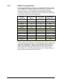
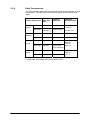
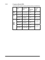
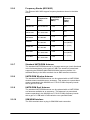
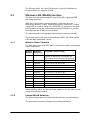
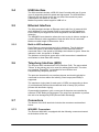
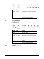
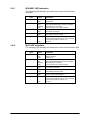
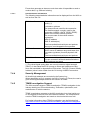
W2x Series
Fixed Wireless Terminals for WCDMA/HSDPA Mobile Networks
Technical Product Description
Contents
2
1
W2X SERIES OVERVIEW.........................................................5
1.1
1.2
1.3
1.4
INTRODUCTION ............................................................................5
ERICSSON W20/W21 - DATA TERMINAL .......................................5
ERICSSON W25 – DATA AND VOICE TERMINAL..............................6
ERICSSON W2X FEATURE SUMMARY ............................................6
2
HARDWARE ARCHITECTURE ................................................8
2.1
2.1.1
2.1.2
2.2
2.2.1
2.2.2
2.2.3
2.2.4
2.2.5
2.2.6
2.2.7
2.2.8
2.2.9
2.2.10
2.3
2.3.1
2.3.2
2.4
2.5
2.5.1
2.6
2.7
2.7.1
2.7.2
2.8
2.8.1
2.8.2
POWER SUPPLY...........................................................................8
Power Adapter ...........................................................................8
Battery Backup (W25 only) ........................................................8
UMTS/GSM RADIO INTERFACES .................................................8
UMTS.........................................................................................8
GPRS/EDGE..............................................................................8
HSDPA Throughput Rates.........................................................9
Data Transmission ...................................................................10
Frequency Bands (W20) ..........................................................11
Frequency Bands (W21/W25)..................................................12
Standard UMTS/GSM Antenna................................................12
UMTS/GSM Window Antenna .................................................12
UMTS/GSM Roof Antenna.......................................................12
SIM/USIM Interface..................................................................12
WIRELESS LAN (WLAN) INTERFACE ..........................................13
Wireless Radio Channels.........................................................13
Internal WLAN Antennas .........................................................13
USB INTERFACE ........................................................................14
ETHERNET INTERFACE ...............................................................14
Built-in LED indicators..............................................................14
TELEPHONY INTERFACE (W25)...................................................14
CONNECTORS............................................................................14
W20/W21 Connectors..............................................................14
W25 Connectors ......................................................................15
LED INDICATORS .......................................................................15
W20/W21 LED Indicators.........................................................16
W25 LED Indicators .................................................................16
3
DATA FEATURES AND FUNCTION ......................................17
3.1
3.1.1
3.1.2
3.2
3.2.1
3.2.2
3.2.3
3.2.4
3.2.5
3.2.6
3.2.7
3.2.8
3.2.9
LAYER 2 FUNCTIONS ..................................................................17
Bridging LAN and WLAN .........................................................17
WLAN Whitelist ........................................................................17
INTERNET PROTOCOL SERVICES ................................................17
IP Forwarding...........................................................................17
DNS .........................................................................................17
DHCP Server ...........................................................................17
SNTP .......................................................................................17
NAT..........................................................................................17
IP Quality of Service ................................................................18
UPnP........................................................................................18
VPN Pass-Through ..................................................................18
PPP Clients..............................................................................18
221 02-FGB 101 327 Uen C - December 2006
3.2.10
3.3
3.4
SIP (W25 only).........................................................................18
USB SERVICES .........................................................................18
AUTHENTICATION .......................................................................19
4
TELEPHONY FEATURES (W25 ONLY) .................................20
4.1
4.1.1
4.1.2
4.1.3
4.2
4.3
4.3.1
4.3.2
4.3.3
4.3.4
4.3.5
4.4
4.5
LINE INTERFACE ........................................................................20
Ringing Signal..........................................................................20
CLIP, CWI and Voice Mail Alert ...............................................20
Hook Flash...............................................................................20
UMTS/GSM SUPPLEMENTARY SERVICES ..................................20
DIAL PROCESS ..........................................................................21
Dialed Number Modification.....................................................21
Local Call Prefix .......................................................................21
Fixed Number Dialing ..............................................................21
Fax Dialing ...............................................................................21
Supplementary Services ..........................................................21
DTMF TRANSMISSION ...............................................................22
EMERGENCY CALLS ...................................................................22
5
FAX SUPPORT (W25 ONLY)..................................................23
5.1
5.2
5.3
5.3.1
5.3.2
5.3.3
SIGNALING.................................................................................23
SECURITY ..................................................................................23
MEDIA STREAM ..........................................................................23
Jitter Buffer...............................................................................23
Echo Canceller.........................................................................23
QoS..........................................................................................23
6
WIRELESS LAN (WLAN)........................................................24
6.1
6.2
6.2.1
6.2.2
6.2.3
SSIDS .......................................................................................24
WIRELESS SECURITY .................................................................24
WEP.........................................................................................24
WPA / WPA2............................................................................24
Whitelist ...................................................................................24
7
CONFIGURATION AND MANAGEMENT...............................25
7.1
7.2
7.3
7.4
7.4.1
7.4.2
7.4.3
7.4.4
7.4.5
WEB USER INTERFACE...............................................................25
COMMAND LINE INTERFACE ........................................................25
ACCESS CONTROL .....................................................................25
MANAGEMENT TOOLS ................................................................26
Software Update ......................................................................26
System Log ..............................................................................26
Fault Management ...................................................................26
Security Management ..............................................................27
TEMS Investigation Support ....................................................27
8
SECURITY...............................................................................28
8.1
8.2
8.3
OPERATOR LOCK .......................................................................28
PIN LOCK ..................................................................................28
MECHANICAL ANTI-THEFT KIT ....................................................28
9
REGULATORY APPROVALS ................................................29
9.1
9.2
9.3
ROHS DIRECTIVE ......................................................................29
WEEE MARKING .......................................................................29
SAR..........................................................................................29
221 02-FGB 101 327 Uen C – December 2006
3
4
9.4
9.5
ENVIRONMENTAL .......................................................................29
INTENDED USE ..........................................................................29
10
ACRONYMS AND ABBREVIATIONS.....................................30
221 02-FGB 101 327 Uen C - December 2006
1
W2x Series Overview
1.1
Introduction
The Ericsson Fixed Wireless Terminal (FWT) W2x product series is the
base for Ericsson WCDMA/HSDPA FWTs. The W2x product series is
based on a platform concept aiming at providing a set of differentiated
terminals from well-defined technical platforms.
The W2x product series consist of different types of terminals. Currently
there are three terminals in the W2x product series:
•
Ericsson W20 – Data Terminal
- W20a for 850/1900 MHz frequency bands
- W20e for 2100 MHz frequency bands
•
Ericsson W21 – Data Terminal
•
Ericsson W25 – Data and Voice Terminal
With WCDMA/HSDPA WAN radio access capability the W2x products are
well suited to provide broadband data access with data speeds similar to
fixed line DSL services.
1.2
Ericsson W20/W21 - Data Terminal
The Ericsson W20/W21 provide data capabilities such as data access (e.g.
Internet) in the respect that it allows multiple computers to be connected to
the terminal using Ethernet or wireless LAN (WLAN).
Figure 1 - Overview of Interfaces for the Ericsson W20/W21
221 02-FGB 101 327 Uen C – December 2006
5
1.3
Ericsson W25 – Data and Voice Terminal
The Ericsson W25 data and voice terminal incorporates the same set of
data features as the Ericsson W20/W21. Additionally, this model also
includes voice and fax capabilities over standard analog telephone
interfaces. A broad range of network services such as Prepaid
Subscription, CLI (Calling Line Identification), Call Waiting, Call Barring,
Call Forwarding, Multiparty Conference Calls are supported.
WCDMS/HSDPA radio access is well suited for combined and efficient data
and voice transmission over the mobile network.
Figure 2 - Overview of Interfaces for the Ericsson W25
1.4
Ericsson W2x Feature Summary
The main features of the Ericsson W2x terminals are:
6
•
Multimode broadband WAN connectivity
WCDMA/HSDPA (850/1900/2100 MHz) as primary access and
GSM/GPRS/EDGE (850/900/1800/1900 MHz) as fall-back. Peak
download data rates 1.8 Mbps for Ericsson W20 and 3.6 Mbps for
the Ericsson W21/W25. (The Ericsson W21/W25 is software
upgradeable to 7.2 Mbps).
•
Four ports Ethernet switch;
Routing, NAT, ALG, DHCP and DNS Server.
•
Two USB 2.0 ports;
File and printer sharing.
221 02-FGB 101 327 Uen C - December 2006
•
Wireless LAN Access Point;
IEEE 802.11b/g (Wi-Fi)
•
Wireless security;
WEP, WPA-PSK, WPA2-PSK, MAC Association Control.
•
Analogue voice services (W25 only);
Via a telephony line interface with high speech quality.
•
Analogue fax services (W25 only);
Using T.38 Fax over IP protocol.
•
Local Administration;
Built-in web based configuration tool with wizard support.
•
SW auto update
•
Remote Management Capability
Via SSH
221 02-FGB 101 327 Uen C – December 2006
7
2
Hardware Architecture
2.1
Power Supply
The W2x terminals can be powered from:
•
•
2.1.1
AC Mains via an external AC/DC power adapter (10-28 VDC)
Battery backup (Ericsson W25).
Power Adapter
The provided power adapter has the following characteristics:
Input: 100-240V AC, 50-60 Hz, 3 pole AC inlet connector (IEC 320 power
inlet).
Output: 12 VDC.
Power consumption: 7.0 W (typical) and 11.4 W (maximum) for Ericsson
W20/21 and 9.0 W (typical) and 16.2 W (maximum) for Ericsson W25.
National power plugs are available for EU, UK, US and AU.
2.1.2
Battery Backup (W25 only)
The Ericsson W25 can be fitted with a rechargeable battery to provide
redundancy in case of an AC Mains power failure. The battery is available
as an accessory and is facilitated within the unit. Additionally there is an
internal battery charger that can recharge the battery.
2.2
UMTS/GSM Radio Interfaces
The W2x terminals support UMTS and GSM/GPRS/EDGE radio interfaces
where UMTS is the primary interface.
2.2.1
UMTS
The W2x terminals support UMTS 850/1900 MHz and 2100 MHz frequency
bands.
The UMTS interface supports the following characteristics:
•
•
•
WCDMA
HSDPA Category 11 and 12 (W20)
HSDPA Category 1-6 and 11 (W21/W25)
The Ericsson W21/W25 is software upgradeable to 7.2 Mbps which means
support for HSDPA Category 7 and 8.
2.2.2
GPRS/EDGE
The W2x terminals support GSM/GPRS/EDGE 850/900/1800/1900 MHz
frequency bands.
8
221 02-FGB 101 327 Uen C - December 2006
2.2.3
HSDPA Throughput Rates
The peak download speed is rated up to 1.8 Mbps for the Ericsson W20
and 3.6 Mbps for the Ericsson W21 and Ericsson W25. The peak up-link
speed is 384 kbps. The rated HSDPA peak download speeds will
eventually evolve up to 14.4 Mbps with enhanced radio performance
(increased modulation and coding schemes) according to the table below
(current W2x rated peak speeds highlighted):
Category
(HS-DSCH)
Peak data rate
(Mbps)
No of codes
(HS-DSCH)
Modulation
(16QAM/QPSK)
Category 1
1.2
5
Both
Category 2
1.2
5
Both
Category 3
1.8
5
Both
Category 4
1.8
5
Both
Category 5
3.6
5
Both
Category 6
3.6
5
Both
Category 7
7.2
10
Both
Category 8
7.2
10
Both
Category 9
10.7
15
Both
Category 10
14.4
15
Both
Category 11
0.9
5
QPSK
Category 12
1.8
5
QPSK
However peak upload speeds are only possibly with normal usage in a cell
and with optimal signal conditions. Typical download speeds experienced
by the users with multiple concurrent voice and data users in the cell,
ranges from 0.6 Mbps to 1.1 Mbps on average with current W2x series
radio configuration according to simulations in urban and suburban
environments. This rate will eventually evolve up to 6-7 Mbps with future
radio configuration updates of the W2x series.
221 02-FGB 101 327 Uen C – December 2006
9
2.2.4
Data Transmission
The W2x terminals offer both circuit switched and packet switched of data
transmission. The table below summarizes typical and theoretical data
rates:
Theoretical
Typical
Packet data service max data
data rate
rate
Category/
Multislot class
Upload
384 kbps
Over 300 kbps
Category
11 and 12
Download
1.8 Mbps
3.6 Mbps (*)
500-800 kbps
1-6 and 11 (*)
Upload
384 kbps
Over 300 kbps
Download
384 kbps
Over 300 kbps
Upload
118 kbps
50-60 kbps
Download
236 kbps
100-130 kbps
(with bursts
over 200 kbps)
Upload
43 kbps
20 kbps
Download
86 kbps
40 kbps
HSDPA
WCDMA
EDGE
GPRS
Multislot
class 10
MCS 1-9
Multislot
class 10
CS 1-4
(*) Applicable for Ericsson W21 and Ericsson W25.
10
221 02-FGB 101 327 Uen C - December 2006
2.2.5
Frequency Bands (W20)
The Ericsson W20 supports frequency bands as shown in the table below:
W20e
Band
Frequencies
(MHz)
Conducted
Rx
sensitivity
(dBm)
Conducted
Transmit
Power
(dBm)
Band I
UMTS 2100
Tx: 1920-1980
Rx: 2110-2170
< -109
+23
Band II
UMTS 1900
Tx: 1850-1910
Rx: 1930-1990
< -109
+23
Band V
UMTS 850
Tx: 824-849
Rx: 869-894
< -109
+23
GSM850
Tx: 824-849
Rx: 869-894
< -106
EGSM 900
Tx: 880-915
Rx: 925-960
< -106
DCS 1800
Tx: 1710-1785
Rx: 1805-1880
< -106
PCS 1900
Tx: 1850-1910
Rx: 1930-1990
< -106
W20a
W20a
and
W20e
221 02-FGB 101 327 Uen C – December 2006
+32 (GMSK)
+27 (8PSK)
+29 (GMSK)
+26 (8PSK)
11
2.2.6
Frequency Bands (W21/W25)
The Ericsson W21/W25 support frequency bands as shown in the table
below:
2.2.7
Band
Frequencies
(MHz)
Conducted Rx
sensitivity
(dBm)
Conducted
Transmit
Power
(dBm)
Band I
UMTS 2100
Tx: 1920-1980
Rx: 2110-2170
< -109
+23
Band II
UMTS 1900
Tx: 1850-1910
Rx: 1930-1990
< -109
+23
Band V
UMTS 850
Tx: 824-849
Rx: 869-894
< -110
+23
GSM850
Tx: 824-849
Rx: 869-894
< -106
EGSM 900
Tx: 880-915
Rx: 925-960
< -106
DCS 1800
Tx: 1710-1785
Rx: 1805-1880
< -106
PCS 1900
Tx: 1850-1910
Rx: 1930-1990
< -106
+32 (GMSK)
+27 (8PSK)
+29 (GMSK)
+26 (8PSK)
Standard UMTS/GSM Antenna
The standard UMTS/GSM antenna is of quarter wave type (omni-directional
in the horizontal plane), with a gain of 2 dBi. The antenna is penta-band
supporting the 800/900/1800/1900/2100 MHz frequency bands. It is
attached directly to the W2x terminals via an SMA antenna connector.
2.2.8
UMTS/GSM Window Antenna
The standard UMTS/GSM antenna can be replaced with an UMTS/GSM
window antenna available as an accessory. This antenna is a penta-band
antenna operating in the 824-960 and 1710-2170 MHz frequency bands
with a gain of 2.15 dBi.
2.2.9
UMTS/GSM Roof Antenna
The standard UMTS/GSM antenna can be replaced with an UMTS/GSM
roof antenna available as an accessory. This antenna is a penta-band
antenna operating in the 824-960 and 1710-2170 MHz frequency bands
with a gain of 11 dBi with 0.5 dBi variation over specified bands.
2.2.10
SIM/USIM Interface
The W2x terminals have a plug-in SIM/USIM card connection.
12
221 02-FGB 101 327 Uen C - December 2006
The Ericsson W20e, W21 and W25 support 1.8 and 3V SIM while the
Ericsson W20a only supports 3V SIM.
2.3
Wireless LAN (WLAN) Interface
The W2x terminals act as wireless Access Point (AP) supporting IEEE
802.11b/g standards.
IEEE 802.11b operates in the unlicensed 2.4 GHz band and can
theoretically achieve 11 Mb/s. Practical throughput, ranges from ~7 Mb/s
(using UDP) to ~6 Mb/s (using TCP). IEEE 802.11g operates in the same
band as 802.11b and has a theoretical top speed of 54 Mb/s. In practice,
throughput around 25 Mb/s is more realistic.
The transmit power is configurable and is limited to maximum 20 dBm.
For wireless security the W2x terminals support WEP, WPA-PSK, WPA2PSK and MAC Association Control.
2.3.1
Wireless Radio Channels
The table below shows the IEEE 802.11 channels and their corresponding
center frequencies:
Channel
Number
Channel
Frequency
Geographic Indoor Usage
1
2412 MHz
US (United States), CA (Canada), ETSI (ETSI
Countries), SI (Singapore), AS (Australia), NZ
(New Zealand), SA (South Africa), MA (Malaysia)
2
2417 MHz
US, CA, ETSI, SI, AS, NZ, SA, MA
3
2422 MHz
US, CA, ETSI, SI, AS, NZ, SA, MA
4
2427 MHz
US, CA, ETSI, SI, AS, NZ, SA, MA
5
2432 MHz
US, CA, ETSI, SI, AS, NZ, SA, MA
6
2437 MHz
US, CA, ETSI, SI, AS, NZ, SA, MA
7
2442 MHz
US, CA, ETSI, SI, AS, NZ, SA, MA
8
2447 MHz
US, CA, ETSI, SI, AS, NZ, SA, MA
9
2452 MHz
US, CA, ETSI, SI, AS, NZ, SA, MA
10
2457 MHz
US, CA, ETSI, SI, AS, NZ, SA, MA
11
2462 MHz
US, CA, ETSI, SI, AS, NZ, SA, MA
12
2467 MHz
ETSI, SI, AS, NZ, SA, MA
13
2472 MHz
ETSI, SI, AS, NZ, SA, MA
Radio scanning makes the W2x terminals capable of sensing other access
points of the allowed channel.
2.3.2
Internal WLAN Antennas
The W2x terminals have two internal WLAN antennas (omni-directional).
The antennas are mounted orthogonally for best performance.
221 02-FGB 101 327 Uen C – December 2006
13
2.4
USB Interface
The W2x terminals include a USB 2.0 Host Controller with two (2) ports
(type A) supporting both full speed and high-speed. The USB interface
supports one low power device per port hence the maximum power
consumption of a device is 100 mA.
Maximum practical cable length for USB is 5 m.
2.5
Ethernet Interface
The W2x terminals include an Ethernet switch with four (4) external LAN
4x10/100BaseTx ports (female RJ45) for connection to PC equipment.
Each Ethernet port supports rate auto-negotiation and MDI/MDIX autodetection.
The MDI/MDIX auto detection allows the user to plug in either a straight or
crossed Ethernet cable regardless of how the other end is connected.
Maximum cable length for Ethernet is 100 m.
2.5.1
Built-in LED indicators
Each Ethernet connector has two built-in indicators. The left indicator
shows the speed of data traffic between the W2x terminals and the
connected client. If the speed is 100 Mbps, the indicator is green. When the
indicator is unlit, the speed is 10 Mbps.
The indicator to the right is green when a LAN connection is established
and flashes to show data traffic activity.
2.6
Telephony Interface (W25)
The Ericsson W25 includes dual POTS interface (FxS). The port marked
“Phone” is the primary port to be used for making phone calls. The other
port (marked “Phone/Fax”) is intended for fax machines and
complementary telephony services.
The ports are intended for on premises phones and should typically be
connected to devices within one building. Short loops (max 500Ω) is
supported.
The maximum ringing load for each port is 3 REN (corresponding to three
(3) old fashioned phones with mechanical bells or twenty (20) modern
phones with electronic ringing).
Characteristic impedance, gain, current etc of the ports are controlled by
software. DTMF dialing are supported. The ports have protection to prevent
the unit to be damaged by ESD (Electro Static Discharge).
2.7
Connectors
The bottom of the W2x terminals includes the connectors as described
below.
2.7.1
W20/W21 Connectors
The Ericsson W20/W21 is equipped with the following connectors located
at the bottom of the unit:
14
221 02-FGB 101 327 Uen C - December 2006
Text
Type
Function
10-28
VDC
Circular
Standard power inlet for connecting the included
power supply adapter.
Reset
Switch
A small hole in the housing. Used to restore the
unit to its factory default configuration.
USB
2 x USB-A
USB connectors, for connecting USB devices to
the unit, e.g. printer or mass storage.
4 x RJ45
Ethernet LAN connectors for connecting the unit
to client PCs or an Ethernet switch/hub.
LAN 1-4
2.7.2
W25 Connectors
The Ericsson W25 is equipped with the following connectors located at the
bottom of the unit:
Text
Type
Function
10-28
VDC
Circular
Standard power inlet for connecting the included
power supply adapter.
Reset
Switch
A small hole in the housing. Used to restore the
unit to its factory default configuration.
USB
2 x USB-A
USB connectors, for connecting USB devices to
the unit, e.g. printer or mass storage.
Phone
RJ11
Phone connector for connecting a standard
analog phone.
Phone/
Fax
RJ11
Phone connector for connecting a standard
analog phone or fax. This port is dedicated for fax
connection.
4 x RJ45
Ethernet LAN connectors for connecting the unit
to client PCs or an Ethernet switch/hub.
LAN
2.8
LED Indicators
The front panel of the W2x terminals include the LED indicators as
described below.
221 02-FGB 101 327 Uen C – December 2006
15
2.8.1
W20/W21 LED Indicators
The following LED indicators are visible on the front of the Ericsson
W20/W21:
Text
Color
Function
Power
Green
Unlit
Power is on.
Power is off.
Mobile Network
Green
Red
Flashing
Unlit
The UMTS network is available.
The GSM (GPRS/EDGE) network is available.
Searching for a connection.
No connection to the mobile network.
Internet
Green
Unlit
Connection to Internet established.
No Internet connection.
Wireless LAN
Green
Unlit
The Wireless LAN is active.
The Wireless LAN is inactive.
Alarm
Red
Error. Various error conditions (specified on the
Overview web page and as an “error” message
in the syslog). Refer to section 7.4.2 .
No error.
Unlit
2.8.2
W25 LED Indicators
The following LED indicators are visible on the front of the Ericsson W25:
Text
Color
Function
Power
Green
Red
Unlit
Mains powered.
Battery powered.
Power is off.
Mobile Network
Green
Red
Flashing
Unlit
The UMTS network is available.
The GSM (GPRS/EDGE) network is available.
Searching for a connection.
No connection to the mobile network.
Internet
Green
Unlit
Connection to Internet established.
No Internet connection.
Wireless LAN
Green
Unlit
The Wireless LAN is active.
The Wireless LAN is inactive.
Message Waiting
Green
Unlit
New voice mail message(s) received.
No new voice mail messages.
Alarm
Red
Error. Various error conditions (specified on the
Overview web page and as an “error” message
in the syslog). Refer to section 7.4.2 .
No error.
Unlit
16
221 02-FGB 101 327 Uen C - December 2006
3
Data Features and Function
3.1
Layer 2 Functions
3.1.1
Bridging LAN and WLAN
The W2x terminals support bridging/switching traffic between the LAN and
WLAN interfaces.
3.1.2
WLAN Whitelist
The W2x terminals support WLAN whitelist, also known as “MAC
Association Control” or “MAC Access List”. Up to 20 WLAN MAC
addresses can be added to the list and the use of the whitelist is possible to
enable/disable.
3.2
Internet Protocol Services
The Internet Services in the W2x terminals are based on the Internet
Protocol version 4 (IPv4).
3.2.1
IP Forwarding
The W2x terminals support IP forwarding and employs ingress traffic
filtering on both the LAN and the WAN interfaces.
3.2.2
DNS
The W2x terminals include a DNS proxy server which responds to DNS
requests from the local LAN/WLAN. It contains a small database of local
host names and addresses supplied by client DHCP requests.
In addition it also caches requests to remote DNS servers.
3.2.3
DHCP Server
The W2x terminals include a DHCP server for LAN/WLAN interfaces.
The DHCP server maintains a pool of IP addresses and distributes them to
LAN/WLAN hosts whenever they are switched on. It also puts the
hostname, supplied by the client DHCP request, in the local DNS proxy.
3.2.4
SNTP
The W2x terminals include a SNTP client which provides a way to
synchronize the device’s own time of day setting with a remote NTP server.
It is possible to specify up to three (3) different SNTP servers (for fallback).
3.2.5
NAT
The W2x terminals support dynamic one-to-many NAT - also known as
NAPT. NAPT translates the source IP address of the LAN to the public
WAN IP address. It also changes the source port (UDP or TCP) or the
ICMP for the WAN to LAN flow. Port translation allows several LAN devices
to be connected to the WAN through one public IP address.
221 02-FGB 101 327 Uen C – December 2006
17
3.2.5.1
NAT Port Forwarding
The NAT Port Forwarding feature, sometimes referred to as Virtual Server,
redirects traffic from the WAN side to a server on the LAN side.
The Port Forwarding feature requires a public WAN IP address on the W2x
terminals.
3.2.5.2
NAT ALGs
An ALG enables the transfer of specific application streams through firewall
policies and NAT. This is enabled by creating dynamic holes in the firewall
policy and NAT and changing IP addresses in network protocol headers,
and if a secondary port is required, the ALG will open one.
The W2x terminals include NAT ALGs for the following protocols:
•
•
FTP
TFTP
The included ALGs can be enabled/disabled individually and do not require
any additional configuration.
3.2.6
IP Quality of Service
The QoS service in the W2x terminals support the Stochastic Fair Queuing
(SFQ) scheduling algorithm which makes sure that no single session can
dominate outgoing bandwidth.
The QoS feature applies for upstream traffic only.
3.2.7
UPnP
The W2x terminals support the UPnP standard with respect to the Internet
Gateway Device (IGD) profile, used by Microsoft Messenger (among
others) to configure port forwarding in a NAT router.
3.2.8
VPN Pass-Through
The W2x terminals support IPSec VPN (Virtual Private Network) passthrough.
3.2.9
PPP Clients
The W2x terminals include a PPP client for WAN access.
For authentication both the PAP (Password Authentication Protocol) and
CHAP (Challenge Handshake authentication Protocol) protocols are
supported.
3.2.10
SIP (W25 only)
The Ericsson W25 supports the SIP protocol (RFC 3261) for T.38 Fax over
IP.
3.3
USB Services
The W2x terminals function as a network storage device for LAN hosts
using SMB/CIFS (as printer and file sharing in Windows).
18
221 02-FGB 101 327 Uen C - December 2006
It is possible to have two storage devices or a storage device and a printer
connected to the W2x terminal at the same time. When an external hub is
connected, the W2x terminals support connection of up to two storage
devices and one printer at the same time. Both USB 1.1 and 2.0 (full speed
and high-speed) are supported.
3.4
Authentication
Authentication towards the UMTS/GSM radio network can be done via
either PIN code or PPP username and password.
221 02-FGB 101 327 Uen C – December 2006
19
4
Telephony Features (W25 only)
The Ericsson W25 provides analogue voice services via the telephony line
interface with high speech quality.
4.1
Line Interface
The POTS (FxS) interface can be configured, i.e. impedance, frequency,
cadence, levels etc.
DTMF dialing is supported.
4.1.1
Ringing Signal
It is possible to configure different ringing signals depending on the call
type.
The mapping and ring frequency are also configurable.
4.1.2
CLIP, CWI and Voice Mail Alert
The Ericsson W25 supports CLIP (Calling Line Identification Presentation)
service in both on-hook and off-hook state using the DTMF and FSK
protocols and is also supporting Bellcore standard.
It is possible to configure a country specific profile for the CLIP services.
The Ericsson W25 also supports the CWI (Call Waiting Indication) service
over the POTS interface. If there is a message in the user voice mailbox
this is indicated by the “Message Waiting” LED and by a special tone
played in the telephone.
The “Message Waiting” LED and tone is activated/deactivated by OTA
SMS messages.
4.1.3
Hook Flash
Hook flash functionality for the POTS interface is supported and
configurable.
4.2
UMTS/GSM Supplementary Services
The Ericsson W25 supports UMTS/GSM supplementary services as listed
below. In order to use the services, the operator network must support
them. Offered supplementary services can only be used with a DTMF
telephone connected to the unit.
•
•
•
•
•
•
•
20
Calling Line Identification Presentation (CLIP)
Calling Line Identification Restriction (CLIR)
Call Forwarding Unconditional
Call Forwarding on Mobile Subscriber Busy
Call Forwarding on No Reply
Call Forwarding on Mobile Subscriber Not Reachable
Call Waiting
221 02-FGB 101 327 Uen C - December 2006
•
•
•
•
•
•
•
4.3
Call Hold
Multi Party Service
Barring of All Outgoing Calls
Barring of Outgoing International Calls
Barring of Outgoing Internal Calls except those directed to the
Home PLMN Country
Barring of All Incoming Calls
Barring of Incoming Calls when Roaming Outside the Home
PLMN Country.
Dial Process
The Ericsson W25 supports E.164 numbering. There are three ways to
indicate that the dialed number sequence is complete:
•
•
•
Dialing the EON key (e.g. # or *) immediately sends the call.
An Inter Digit Timer (IDT) is used to check the dialing process.
A specified number of digits must be dialed before the call is
placed.
The EON key is configurable as well as the IDT.
4.3.1
Dialed Number Modification
It is possible to do number modifications, e.g. remove and/or add digits to a
dialed number.
The dial plan consists of a pattern string to match dialed digits, and the
ability to strip, append prefix digits, and/or append suffix digits.
4.3.2
Local Call Prefix
A local prefix can automatically be added to a dialed local number. This is
useful in places where the PSTN does not require the local prefix in local
calls.
4.3.3
Fixed Number Dialing
Fixed Number Dialing is supported when a SIM providing this service is
installed. When enabled, only calls to fixed numbers stored on the SIM are
allowed.
4.3.4
Fax Dialing
A local fax call is detected through a unique prefix before the phone
number. The fax prefix is configurable and is removed before the T.38 call
is setup.
4.3.5
Supplementary Services
The UMTS/GMS supplementary service codes (i.e. #67# etc) is possible to
configure with a service code of choice, in order to have the same service
codes as in a fixed network.
221 02-FGB 101 327 Uen C – December 2006
21
4.4
DTMF Transmission
The Ericsson W25 is capable of transmitting DTMF on the radio interface
as received on the 2W-line interface using message based signaling.
It is possible to switch of the DTMF message based signaling so that DTMF
tones go through the voice code.
The Ericsson W25 supports DTMF digits 0-9 and A&B.
4.5
Emergency Calls
Emergency calls (i.e. 112 or 911) can always be made, even without a SIM
card or the correct PIN code. This also applies if the terminal is locked to
the network by a specific MCC and/or MNC or if the PIN Lock feature is
enabled.
The emergency telephone number may differ from country to country. It is
typically a three-digit number so that it can be easily remembered and
dialed quickly. Some countries have a different emergency number for each
of the different emergency services; these often differ only by the last digit.
Emergency calls have its own dial plan and multiple numbers can be
configured.
22
221 02-FGB 101 327 Uen C - December 2006
5
Fax Support (W25 only)
To enable Fax support the Ericsson W25 uses the Voice over IP (VoIP)
protocol called SIP.
The Ericsson W25 works as a fax gateway between the POTS interface
and the IP network using the T.38 protocol. The fax machine is connected
to one of the two POTS interfaces on the Ericsson W25, which is dedicated
for a fax machine.
Connected to this fax port is a SIP user agent, which manages and controls
the media streams by using the SIP protocol towards the SIP server and
media Gateway.
5.1
Signaling
The Ericsson W25 conforms to the SIP protocol (RFC 3261).
5.2
Security
The Ericsson W25 authenticates towards the VoIP system using the HTTP
Digest Authentication mechanism.
5.3
Media Stream
To transfer the fax call the T.38 protocol is used.
5.3.1
Jitter Buffer
To handle latency and jitter the W25 has a jitter buffer.
5.3.2
Echo Canceller
To improve the fax transfer, the Ericsson W25 has an echo canceller in
accordance with G.168.
5.3.3
QoS
The outgoing VoIP related traffic will be prioritized before other traffic from
the Ericsson W25 to reduce the uplink delay and jitter.
221 02-FGB 101 327 Uen C – December 2006
23
6
Wireless LAN (WLAN)
6.1
SSIDs
The W2x terminals support single SSID. This SSID and a unique MAC
address are broadcasted in the beacon at regular intervals.
The SSID name can be set (changed) with a maximum length of 32
alphanumeric characters. It is also possible to configure the SSID to be
hidden.
The SSID can be either “open” (no authentication or encryption) or “closed”
(meaning either WEP or WPA security). See below for security details.
6.2
Wireless Security
Authentication and data encryption are used to restrict access to the
wireless network. Which authentication and encryption method that should
be used depends on what is supported by the connecting wireless
device(s).
The W2x terminals support the following WLAN security protocols:
•
•
•
6.2.1
WEP with both 64- and 128-bit key lengths.
WPA-PSK
WPA2-PSK
WEP
WEP enables wireless security using 64-bit or 128-bit data encryption.
WEP encryption requires a private network key. Each device in the wireless
network has to be manually configured with this key.
6.2.2
WPA / WPA2
WPA is a 256-bit data encryption method with keys that dynamically
change over time. WPA and its successor WPA 2 are considered to be the
most reliable security options.
For user authentication WPA/WPA2 runs a special, easy-to-set-up home
mode called Pre-Shared Key (PSK) where keys and passphrases are
manually entered.
WPA encryption uses the Temporal Key Integrity Protocol (TKIP) while
WPA2 encryption follows the Advanced Encryption Standard (AES).
6.2.3
Whitelist
A common method of restricting WLAN network access is to specify the
MAC address(es) in a so called “whitelist” for those computers access are
granted. Up to 20 MAC addresses for wireless clients can be added to the
whitelist. This feature does not require any configuration of the clients but
on the other hand it does not encrypt the traffic like WEP/WPA.
24
221 02-FGB 101 327 Uen C - December 2006
7
Configuration and Management
7.1
Web User Interface
The end-user configures the W2x terminals through a web user interface
(WUI) that is accessible through the LAN and WLAN interfaces.
The WUI also includes a Configuration Wizard for easy setup of the local
Internet connection and wireless network.
7.2
Command Line Interface
The CLI is mainly intended for operator service personnel handling tasks
like storing/exchanging configuration files and for maintenance purpose (i.e.
fault location and tracing).
Remote access to the CLI is possible using SSH2 and local access through
Telnet.
7.3
Access Control
The access control in the W2x terminals is applicable for all interfaces, i.e.
CLI, WUI and remote management.
Multiple users and groups are supported and each user has its own
username and password and is a member of one or several groups.
By default there are three accounts available, where:
•
The end-user (user-id user), using the WUI, is allowed to access
functions and configuration parameters related to WAN
authentication, LAN settings, NAT and port forwarding, WLAN
access point and USB file sharing.
This account can only be used when accessing the WUI and has
no access rights to the CLI.
•
The operator (user-id operator), using the CLI, in addition to the
end-user privileges also is allowed to access additional WAN and
telephony related configuration parameters and trouble shooting.
•
An administrator account (user-id root), using the CLI, has full
permissions.
Each configuration parameter has an access control specification
determining what action (read or write) the user/group is allowed to
perform.
221 02-FGB 101 327 Uen C – December 2006
25
7.4
Management Tools
7.4.1
Software Update
The W2x terminals run Linux OS on an Intel hardware platform. The flash
file system is formatted as two partitions, each capable of holding a
complete software image. If a software update process should get
interrupted, e.g. power failure during the update process, there is always a
last known good firmware image to boot from.
7.4.1.1
Manual Software Update
Manual software updates is supported from FTP or HTTP(S) servers. It is
also possible to upgrade the software via a browser button in the WUI from
a local computer.
7.4.1.2
Automatic Software Update
Automatic software updates from Ericsson’s update server are supported.
In this case, the W2x terminals will at regular intervals poll the update
server for updates. If there is an image available a download and upgrade
process is initiated.
7.4.1.3
Backup and Restore Configuration
By using the WUI, the end-user can backup and restore configuration files
to/from a local PC.
7.4.2
System Log
The W2x terminals include a system log accessible both from the CLI and
WUI as a text file.
The system logging information is written to 5 files which are rotated in a
circular fashion. The files are limited to 200Kbytes each, which equals a
maximum of 1 MB total logging information. The files are not saved to flash
and will be lost when rebooting or when power is disconnected.
When persistent logging is enabled, the log files are written to flash
memory in two files alternately.
Different levels of logging (Emergency, Alert, Critical, Error, Warning,
Notice, Info and Debug) can be set depending on how much information is
desired.
The syslog events can be saved to a local file or forwarded to remote
syslog server.
7.4.2.1
BSD Syslog Remote Logging
The W2x terminals are able to distribute none, some or all system log
events using the BSD Syslog message format on UDP.
7.4.3
Fault Management
If an error condition occurs, the “Alarm” LED on the unit is lit (red) and the
corresponding cause is displayed in the WUI (on the Overview page). An
event message with severity level “Error” is also generated in the syslog.
26
221 02-FGB 101 327 Uen C - December 2006
Events that generate an alarm are such that make it impossible to send or
receive data, e.g. SIM card missing.
7.4.3.1
Interface Status and Statistics
The following status/statistics information can be displayed from the WUI as
well as from the CLI:
WAN interface
The mobile network (UMTS or GSM) signal
quality. (*)
Link status: up/down
The protocol/mode used for the connection.
The mobile network currently used for the
connection (HSDPA, UMTS, GPRS, EDGE).
Name of the mobile network operator.
The current state of the mobile network
registration.
WAN IP address
DNS IP address(es)
LAN interface
WLAN interface
Total transmitted/received bytes and packets
Amount of error/dropped/overrun packets
LAN IP address and subnet mask
DHCP server IP address range and lease time
Port status (up/down) for each physical LAN
port
Total transmitted/received bytes and packets
Current associations (MAC address)
Current successful authenticated associations
(MAC address and state)
(*) The visual signal quality bars are not only based on signal strength
(RSCP). It also takes the EC/I0 (energy to noise and interference ratio),
since the bandwidth is depended on both values. The CQI (Channel Quality
Indicator) value is also visible from the CLI during a HSDPA connection.
7.4.4
Security Management
All invalid login attempts are recorded in the System Log.
When attempting to log in remotely via SSH or locally via Telnet, the user is
given three login attempts and then the session is ended.
7.4.5
TEMS Investigation Support
The W2x terminals support TEMS Investigation. TEMS Investigation is the
industry-leading tool for troubleshooting, verification, optimization, and
maintenance of mobile networks.
TEMS Investigation connects to the W2x terminals via a virtual serial port
on a computer to the W2x over the Ethernet interface. The computer that
runs the TEMS investigation tool needs a virtual serial driver as well.
For further information about TEMS Investigation, see the following link:
http://www.ericsson.com/solutions/tems/realtime_diagnostics/investigation.
shtml
221 02-FGB 101 327 Uen C – December 2006
27
8
Security
The basic security feature of the W2x terminals are the same as any GSM
phone, using a PIN code that comes with the subscription SIM card. The
PIN code is simply entered via the WUI. To simplify usage, the W2x
terminals have an auto PIN feature that requires the PIN code only to be
entered the first time the unit is used or upon changing the SIM card.
Additionally the W2x terminals provide security features that prevent
unauthorized use of the SIM card and the unit, which can be customized if
required.
8.1
Operator Lock
This feature controls the W2x terminals network access, based on whether
the SIM matches one or more of the following criteria:
•
•
Mobile Country Code (MCC) and Mobile Network Code (MNC)
Additional Mobile Country Code (MCC+) and Additional Mobile
Network Code (MNC+)
MCCs are defined in ITU E.212 (“Land Mobile Numbering Plan”) for use in
identifying mobile stations in wireless telephone networks, particularly GSM
and UMTS networks. A MCC is often used in combination with a Mobile
Network Code (MNC) in order to uniquely identify a network operator.
Both the MCC and MNC are part of the International Mobile Subscriber
Identity (IMSI) number, which uniquely identifies a particular subscriber,
and is stored on the SIM card.
The unit can be locked to one or two specific mobile network providers.
8.2
PIN Lock
This feature locks the SIM card to a unique unit by changing the PIN code
to a new randomly value. As a result, the SIM card cannot be used in
another terminal unless the PUK code is known.
8.3
Mechanical Anti-Theft Kit
A mechanical anti-theft kit is available as an accessory. The kit consists of
a wall bracket with an anti-theft detail and a special anti-theft key for
removing a unit that is locked to the wall bracket.
28
221 02-FGB 101 327 Uen C - December 2006
9
Regulatory Approvals
The W2x terminals are certified with EU Directives for the CE mark, Safety
approvals, EMC and Radio Spectrum approvals and RF Exposure
approvals for the following markets:
•
•
•
•
•
•
•
•
9.1
EU
USA
Canada
Australia
New Zealand
Malaysia
South Africa
Singapore.
RoHS Directive
The W2x terminals meet the requirements of the RoHS directive.
9.2
WEEE Marking
The W2x terminals meet the requirements in the WEEE directive and are
marked accordingly.
9.3
SAR
SAR (Specific Absorption Rate) measurements are performed on the W2x
terminals to establish compliance with national and international RF limits.
9.4
Environmental
The W2x terminals meet the following requirements for operational
condition:
•
•
9.5
Temperature: 0oC to +50oC.
Humidity: 5% to 95% RH, non-condensing.
Intended Use
The W2x terminals are intended for indoor private and public use.
221 02-FGB 101 327 Uen C – December 2006
29
10
Acronyms and Abbreviations
ALG
Application Layer Gateway
FWT
Fixed Wireless Terminal
AES
Advanced Encryption Standard
G3
Group 3 (Fax protocol)
AP
Access Point
GMSK
Gaussian Minimum Shift Keying data transmit
APN
Access Point Name
GPRS
General Packet Radio Service
CDMA
Code Division Multiple Access
GSM
Global System for Mobile Communication
CHAP
Challenge Handshake Authentication
Protocol
HSDPA
High Speed Downlink Packet Access
CLI
Command Line Interface
CLI
Calling Line Identification
CLIP
Calling Line Identification Presentation
CLIR
Calling Line Identification Restriction
CWI
Call Waiting Indication
DHCP
Dynamic Host Configuration Protocol
DNS
Domain Name System (or Service)
DSL
Digital Subscriber Line
DTMF
Dual Tone Multi Frequency (signaling)
EDGE
Enhanced Data rates for Global Evolution
EGSM
Enhanced GSM
EON
End Of Number
FTP
File Transfer Protocol
FXS
Foreign eXchange Station
30
IDT
Inter Digit Time
IMSI
International Mobile Subscriber Identity
IP
Internet Protocol
IPv4
Internet Protocol version 4
LAN
Local Area Network
LED
Light Emitting Diode
MCC
Mobile Country Code
MNC
Mobile Network Code
NAT
Network Address Translation
OTA
Over-The-Air programming
PAP
Password Authentication Protocol
PDP
Packet Data Protocol
PIN
Personal Identification Number
POTS
Plain Old Telephone Service
221 02-FGB 101 327 Uen C - December 2006
PPP
Point-to-Point Protocol
VPN
Virtual Private Network
PSK
Pre-Shared Key
WAN
Wide Area Network
PSTN
Public Switched Telephony Network
WCDMA
Wideband CDMA
PUK
Personal Unblocking Key
WEP
Wired Equivalent Privacy
QoS
Quality of Service
WLAN
Wireless LAN
RIP
Routing Information Protocol
WPA
WiFi Protected Access
SIM
Subscriber Identity Module
WUI
Web User Interface
SMS
Short Message Service
SNTP
Simple Network Timing Protocol
SSH
Secure Shell
SSID
Service Set Identifier
TCP
Transmission Control Protocol
TEMS
TEst Mobile Stations
TFTP
Trivial File Transfer Protocol
TKIP
Temporal Key Integrity Protocol
UDP
User Datagram Protocol
UPnP
Universal Plug and Play
UMTS
Universal Mobile Telecommunications
Service
USB
Universal Serial Bus
VAD
Voice Activity Detection
VoIP
Voice over IP
221 02-FGB 101 327 Uen C – December 2006
31
© Ericsson Enterprise AB 2006 – All Rights Reserved
This document contains proprietary information, which is protected by
copyright. No part of this document may be reproduced or transmitted in
any form or by any means, electronic or mechanical, including
photocopying, recording, or by any information storage and retrieval
system, or translated into another language, without prior written consent of
Ericsson Enterprise AB, Stockholm, Sweden.
NOTICE
The information in this document is subject to change without notice.
ERICSSON MAKES NO WARRANTY OF ANY KIND WITH REGARD TO
THIS MATERIAL, INCLUDING, BUT NOT LIMITED TO, THE IMPLIED
WARRANTIES OF MERCHANTABILITY AND FITNESS FOR A
PARTICULAR PURPOSE. Ericsson shall not be liable for errors contained
herein nor for incidental or consequential damages in connection with the
furnishing, performance or use of this material.
Ericsson Enterprise AB
SE-131 89 Stockholm
Telephone +46 8 568 67 000, Telefax +46 8 719 65 60
32
221 02-FGB 101 327 Uen C - December 2006
221 02-FGB 101 327 Uen C – December 2006
33