1
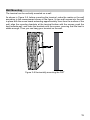
Welcome to ETS1201 Fixed Wireless Terminal (FWT).
User Manual
FWT
Model: ETS1201
Copyright © 2008 Huawei Technologies Co., Ltd.
All Rights Reserved
No part of this manual may be reproduced or transmitted in any form or by
any means without prior written consent of Huawei Technologies Co., Ltd.
Trademarks
and HUAWEI are trademarks of Huawei Technologies Co., Ltd.All
other trademarks mentioned in this manual are the property of their
respective holders.
Notice
The information in this manual is subject to change without notice. Every
effort has been made in the preparation of this manual to ensure accuracy
of the contents, but all statements, information, and recommendations in
this manual do not constitute the warranty of any kind, expressed or
implied.
Contents
1 Warnings and Precautions .................................................................................... 1
2 Overview ............................................................................................................... 5
Packing List .................................................................................................... 5
Front View....................................................................................................... 6
Rear View ....................................................................................................... 7
3 Installation ............................................................................................................. 9
Installing the External Power Adapter/12V SMPS or the Battery.................. 10
Installing Indoor Antenna ...............................................................................11
Connecting the FWT to Telephone ............................................................... 12
Connecting the FWT to a PC........................................................................ 13
Connecting FWT and Facsimile Set (Fax).................................................... 14
Mounting the Terminal .................................................................................. 14
4 General Functions............................................................................................... 16
Preparation for Booting................................................................................. 16
Placing Calls ................................................................................................. 16
Answering Calls ............................................................................................ 17
Adjusting the Voice Volume .......................................................................... 17
Signal Tone ................................................................................................... 18
5 Advanced Functions............................................................................................ 20
Supplementary services ............................................................................... 20
Installing the FWT Manager.......................................................................... 20
Internet Services and SMS services............................................................. 20
6 Facsimile (Fax) Function and Usage Description ............................................... 21
Operation Command Codes (G3 Fax and PC Fax)...................................... 21
Analog Facsimile .......................................................................................... 22
7 Troubleshooting................................................................................................... 24
8 Description of ETS1201FWT .............................................................................. 26
i
1
Warnings and Precautions
Before using HUAWEI Fixed Wireless Terminal (hereinafter referred to as FWT),
read the following cautions and let your children know these, so that you can use
your FWT correctly and safely.
Basic Cautions
y According to the packing list, check items in the package box to make sure
that they are complete and undamaged.
y Before installing and using FWT, read this User Guide carefully.
y Make sure to power off the FWT and disconnect external power supply
before moving or cleaning it.
Electronic Device
Power off your FWT near high-precision electronic devices. The FWT may affect the
performance of these devices.
Such devices include hearing aids, pacemakers, fire alarm systems, automatic
gates, and other automatic-control devices. If you are using an electronic medical
device, consult the device manufacturer and confirm whether the radio waves affect
the operation of the electronic device.
Hospital
Pay attention to the following points in hospitals or health care facilities:
y Do not take your FWT into the operating room (OR), intensive care unit
(ICU), or coronary care unit (CCU).
y Power off your FWT near medial devices.
y Observe any instructions wherever the use of wireless device is prohibited.
Traffic Safety
y Do not use your FWT while driving. Secure the FWT on its holder. Do not
place the FWT on the seat or other places where it can get loose in a
sudden stop or collision.
y Observe the rules and regulations of airline companies. Power off your FWT
before boarding an aircraft.
1
Do’s & Don’ts
y Do not place magnetic storage media such as magnetic cards and floppy
disks near the FWT. Radiation from the FWT may erase the information
stored on them.
y Do not put your FWT, battery, or other accessories in containers with strong
magnetic field, such as the induction cooker and microwave oven.
Otherwise, circuit failure, fire, or explosion may result.
y Do not place or use the FWT, the battery or the power adapter near any heat
sources such as fire or a heater; or places with flammable gases; or areas
with electrical appliances that give out heat. Otherwise, it will cause fire,
explosion and breakdown of the FWT
y Because the FWT needs to eliminate heat during working, put the FWT and
the power supply in a ventilated and shadowy place. Never airproof the FWT
or put something on it or place it near water, fire as well as inflammable and
explosive materials.
y Do not put a towel over the FWT, or put it in a box or a suitcase while using.
y Because the FWT contains precision devices, you should put it in a dry
place and away from moist materials.
y Before cleaning FWT, please power off the FWT, and then disconnect the
power supply and take out the battery. Before moving the FWT, please
disconnect the external power supply.
y Do not subject your FWT, battery, and power adapter to serious collision or
shock. Otherwise, battery leakage, FWT malfunction, overheats, fire, or
explosion may result.
y Do not place sharp metal objects such as pins near the earpiece. The
earpiece may attract these objects and hurt you when you are using the
FWT.
y Do not place the FWT in the area over the air bag or in the air bag
deployment area. Otherwise, the FWT may hurt you owing to the strong
force when the air bag inflates.
y In raining and lightning, disconnect the power adapter from external power
supply and power off the FWT, In this case, if the outdoor antenna is used,
do not touch the FWT and antenna.
y Put your FWT, battery, and power adapter in places beyond the reach of
children. Do not allow children to use the FWT, battery, or power adapter
without guidance.
y Do not touch the antenna when a call is going on. Touching the antenna may
affect call quality and cause the FWT to operate at a power level higher than
needed.
y The network signal condition will directly affect the quality and stability of the
call. Consequently, you should place FWT in a place where it can receive
network signal well. Do not put FWT in a building with an iron or metal roof.
The distance between FWT and other metal materials (such as metal
brackets or metal doors and windows) should be greater than 25cm and the
distance between FWTs should be greater than 30cm.
2
y Do not open the chassis in any case and the device should be maintained
by a qualified maintenance department.
y Without permission, you are not allowed to modify the architecture and
security design of FWT. You must bear any consequence resulted from the
operation without permission
y Your FWT is designed to conform to the authoritative international radio
frequency (RF) specifications. Use FWT accessories approved by Huawei
only.
y Do not use the external telephone outdoors.
y Do not attempt to open the chassis regardless of whether the device is
properly working or problems have occurred. In the latter case, the proper
measure is to select an authorized maintenance agent to repair the device.
y No organizations or individuals are allowed to make modifications to the
device structure or security design, unless authorized by Huawei
Technologies Co., Ltd. (hereinafter referred to as Huawei Technologies).
Huawei Technologies will not assume any responsibility for any
consequences resulted from the modifications without approval.
Emergency Call
You can use your FWT for emergency calls. However, connections in all conditions
cannot be guaranteed. You should never rely solely on the FWT for essential
communications.
Battery
y If the battery fluid gets into eyes, do not rub them. Wash with clean water
and seek medical assistance immediately.
y If the battery fluid contacts skin or cloth, wash with clean water immediately
to avoid irritation to the skin.
y Do not dispose of the battery in fire. Otherwise, the battery may ignite or
explode.
y When installing the battery on your FWT, do not push the battery by force
lest battery fluid leak out or the battery crack.
y Do not connect two poles of the battery with metallic materials such as
cables.
y Do not disassemble the battery or solder the battery poles. Otherwise, fluid
leakage, overheat, fire, or explosion may result.
y If there is battery leakage, smoke, or strange smell, stop using the battery
and keep it away from open flame to avoid fire or explosion.
y Disconnect the power adapter and take out the battery when FWT is not
used for a long time.
y Do select its self-contained complete battery and power adapter; otherwise,
FWT may be spoiled. Huawei Technologies Co., Ltd is not responsible for
any consequences caused by using non-standard batteries or power
supplies. Dispose of used batteries according to the instructions
3
y Dispose of the battery according to local laws or regulations.
Power Adapter
y Use AC power as specified for the power adapter. Any violation of this rule
may result in fire or malfunction of the power adapter.
y Do not short-circuit the power adapter. Short-circuiting the power adapter
may cause fire or malfunction of the power adapter.
y Remove the dust on the power plug regularly.
y Do not put the power adapter near the container filled with liquid such as
water. If the liquid comes into the power adapter, electrical leakage or other
faults may result.
y If the liquid such as water comes into the power adapter accidentally,
remove the plug of the power adapter from the socket immediately.
y Disconnect the power adapter from the socket before cleaning or
maintaining it. Otherwise, electric shock or short-circuiting of the battery or
power adapter may result.
y Ensure the plug of the power adapter is properly inserted into the power
socket when charging the battery. Improper insertion may result in electric
shock, fire, or explosion.
Using the USB Cable
When using the USB cable, observe the following requirements. Otherwise, the
FWT or PC may fail:
y When the USB cable is used to connect the FWT to a PC, connect the USB
cable with the FWT first.
y When the FWT communicates with a PC, do not disconnect the USB cable.
y When disconnecting the USB cable, disconnect it from the PC first
Environmental Protection
Please abide by the local laws in proposing of the package materials of your FWT,
consumed batteries and used FWT, and try to recycle them.
4
2
Overview
Packing List
Check the delivered items against the packing list shown in the table below, and
make sure that all the items are in good conditions. If there is any shortage or
damage, please contact the local agent as soon as possible.
Quantity
Unit
The FWT host
Commodity
1
PCS
Internal Antenna
1
PCS
Power adapter (Optional)
1
PCS
USB Cable
1
PCS
Rechargeable Battery (With Power
Adapter)
1
PCS
User Guide (Hindi & English)
1
PCS
12V SMPS (Optional)
1
PCS
Patch Panel Antenna (Optional)
1
PCS
Feeder cable (With Patch Panel Antenna)
1
PCS
Note:
y Final packing list will be as per the Purchase Order packages.
y The FWT should be configured with an antenna. Please select either an
indoor or an outdoor antenna depending on the local radio signal strength.
For more information, please contact nearest BSNL customer care
centre.
y If you want to use the FWT for accessing the internet, you should also
purchase the required data suite from BSNL customer care centre. For
more information, please consult nearest BSNL customer care centre.
5
Front View
Figure 2-1 illustrates the front view of an FWT host:
9
8
7
1
2
3
4
5
6
1) FWT switch
2) DC input
3) Telephone port 1
4) Telephone port 2
5) USB port
6) Antenna port
7) Power LED
8) Battery LED
9) Receive signal strength LED
Figure 2-1 Front view of the FWT host
The following describes the ports and the LEDs on the host:
FWT switch
The switch is used to turn on or turn off the terminal.
DC input
This port is used to connect the FWT to power adapter.
Telephone port (1,2)
This port is used to connect the device to an external telephone to provide voice
services.
USB port
This port connects to the computer to perform data service and is mainly used for
maintaining the terminal.
Antenna port
This port can be directly connected to an indoor antenna. Also, it can be connected
to an outdoor patch panel antenna via a feeder cable.
6
Power LED
The green LED means that the power adapter is serving for the FWT.
Battery LED
When only using the battery (no power adapter) for power supply, Green LED
means full electricity supply. Orange LED means medium electricity supply. Orange
LED with blinking means poor electricity supply and needs to recharge.
When using external power adapter (with battery installed), Orange LED means the
battery is recharging. Green LED means recharging has been finished.
Receive signal strength LED
The receive signal strength is indicated by four LEDs, the number of lightening
LEDs indicates the strength of signal.
Rear View
Figure 2-2 illustrates the rear view of the FWT host:
1
2
3
4
5
1) Wall-mounting brackets
2) R-UIM card slot
3) Battery port
4) Battery
5) Battery cover
Figure 2-2 The FWT host rear view
The following describes the ports:
Wall-mounting brackets
With the wall-mounting brackets, you can mount the terminal host on the wall.
7
R-UIM card slot
It is used to install R-UIM(Removable-User Identity Module) card.
Battery port
This port is used for the connection with the battery. You only allowed to use the
self-contained complete batteries
Battery
The terminal is configured with a battery in case that the external power adapter
fails to feed the required power.
Battery cover
To maintain the battery, you should first remove its cover.
8
3
Installation
Installing R-UIM Card (Optional)
Note:
y Please consult nearest BSNL customer care centre to decide whether to
install the R-UIM card or not.
y Please turn off the FWT, disconnect the FWT from power adapter and
remove the battery before installing R-UIM card.
y R-UIM card and the contact point are easily to be damaged for scar or
over bending, so you should insert or remove it gently.
Figure 3-1 Installing R-UIM card
1. Open the battery cover and remove the battery.
2. Insert R-UIM card to the slot as the arrow shows in Figure 3-1.Please put the
side that with a corner cutting backwards and the side with a gold contact point
downwards, and then make sure the R-UIM card is completely inserted into the
slot.
3. Restore the battery and install the battery cover.
9
Installing the External Power Adapter/12V SMPS or
the Battery
Note:
y If the FWT is connected to the outdoor patch panel antenna, disconnect
the patch panel antenna before replacing the battery.
y If the FWT is connected to the power adapter and the battery is inserted,
the FWT is powered by the power adapter, and meanwhile, the battery is
charged.
y Charge the battery for at least eight hours for the first time.
y If FWT is powered by a 12V SMPS power supply then the internal battery
is not required. 12V SMPS is provide power as well as backup to the
FWT.
Installing External Power Adapter or 12V SMPS
1. Make sure that the FWT switch of the terminal has been put in the OFF position.
2. Insert one end of power adapter or 12V SMPS into the DC input port in the
direction shown in Figure 3-2, and the other end into the power supply jack.
3. Turn on the FWT switch of the terminal and wait for a few seconds. If the power
LED is green, the connection is correct.
Figure 3-2 Connecting the power adapter with the FWT
10
Installing/Removing Battery
Caution:
To prevent lightning from injuring human body, please note:
If you use outdoors patch panel antenna, remove it before disassembling
and installing battery.
1. Make sure that the power adapter has been powered off and disconnected from
the terminal.
2. Open the cover of the battery as shown in Figure 3-3.
3. First, remove the connection cable from the battery port, and then take out the
battery.
4. When installing the battery, insert the connection cable of the battery into the
battery port on the terminal (please make sure the insert direction), and then
seat the battery in the battery container in the host.
5. Close the battery container cover to complete the battery removal or installation.
Figure 3-3 Removing or installing the battery of the FWT
Installing Indoor Antenna
In an area that signals can be transmitted and received with good quality, you can
install an indoor antenna, as shown in Figure 3-4.
11
Figure 3-4 Installing an indoor antenna for the FWT
1. Make sure to place the switch of the terminal in the OFF position.
2. Align the indoor antenna with the antenna port on the terminal host in the
direction shown in Figure 3-4, and then screw the antenna, ensuring that the
connection is secure.
Connecting the FWT to Telephone
The FWT can provide the conversation services only when it is connected to a
telephone. Figure 3-5 shows the connection:
Figure 3-5 Connecting the FWT to a telephone
As shown in Figure 3-5, connect the telephone to a telephone port on the terminal
via a cable with an RJ11 connector. The terminal provides two telephone ports
respectively numbered 1 and 2. As they are internally interconnected, you can use
either of them.
12
You can use the telephone cable came with the terminal to directly connect the host
of the terminal to a telephone and you can also connect another free telephone port
to some other telephone set. (The two telephones are in parallel connection and
hence use the same number).
Connecting the FWT to a PC
The terminal can be connected to a PC to provide data services.
To use data services, you need to purchase the data service suite and connect the
FWT to a PC, as show in the following Figure 3-6.
Connect the one end of the data cable to PC and the other end to the FWT.
Caution:
y To avoid damaging the device when making connection, power off the
FWT and use the data cable provided with FWT.
y ETS1201 FWT can be connected to a telephone and a PC at the same
time, but the telephone and data services cannot be manipulated
simultaneously. In other words, you can use only one service at a time.
Figure 3-6 Connecting the FWT to a PC
13
Connecting FWT and Facsimile Set (Fax)
Note:
Please affirm that your FWT supports facsimile before using this function.
For detailed model description, please refer to the page 26 “Description of
ETS1201FWT”
Connect the FWT to facsimile set to perform facsimile function.
As shown in Figure 3-7, connect the telephone line interface of the facsimile set to
that of the FWT with a cable (RJ11 connector). FWT provides two telephone line
interfaces - interface 1 and interface 2. These two are interconnected internally and
user can select one of them at will.
Connect the FWT and the facsimile set with a telephone line delivered in the
accessories.
Figure 3-7 Connecting the FWT and the facsimile set via telephone line
Mounting the Terminal
You can place the FWT horizontally or vertically.
Horizontal Mounting
Place the FWT on a flat surface. Select a cool and ventilated site for the Phone to
dissipate the heat.
14
Wall Mounting
The terminal can be vertically mounted on a wall.
As shown in Figure 3-8, before mounting the terminal, make the marks on the wall
according to the measurement shown in the figure, fix two wall screws into the wall
in place with the screw heads extending approximately 3mm from the surface of the
wall, align the mounting brackets at the terminal bottom with the screws, push the
host towards wall, and mate the brackets with the screws, ensuring that the host is
stable enough. Then you can hang your terminal on the wall.
Figure 3-8 Horizontally mounting the FWT
15
4
General Functions
Preparation for Booting
The boot process of the FWT will last about 20 seconds after it is powered on. If the
network signal strength is good enough, the signal LEDs will light after the booting
process is completed. After off hook and dial tone sounds, you can make/answer a
call or send/receive a fax.
Note:
y You should note that if the network signal is too weak, it is likely that all
the signal intensity LEDs will keep off after the FWT is started. In this
case, you are recommended to adjust the height and the direction of the
antenna until you can observe the indication of relatively strong field
intensity.
y If the signal intensity LEDs keep in an ON-OFF state after the
adjustment, the poor network signal quality is irrelevant with the position
of the antenna. Even though you can place or answer calls in this case,
the probability to be successful is low.
y If the LEDs keep off, it is likely that faults have occurred to the terminal or
the network has not covered the area yet. In this situation, please consult
nearest BSNL customer care centre.
Placing Calls
Before off-hook, make sure that at least one signal intensity LED is on. If all the
signal intensity LEDs are off, the signal quality is extremely poor and you will have
little chance to place a call successfully.
Follow these steps to place a call:
1. Hook off and dial upon hearing the dial tone.
2. Dial in either of the following ways.
Method 1: Dial a telephone number in a regular way, and the number will be dialed
out in seven seconds. For example, if you want to dial the telephone number
“4503421”, simply dial all the digits of the number.
16
Note:
You can set the wait time for auto dial-out of the FWT through entering
“##58*n#”, where n is in the range 0 to 9. Setting n to 0 will disable the auto
dial-out function of the FWT. Otherwise, the FWT will automatically dial out
your desired number in n seconds. By default, n is 7 seconds. To validate
this function, you must reboot the terminal.
Method 2: Dial all the digits of the number plus one “#”. In this way, the FWT will
immediately dial the number. For example, if you want to dial the telephone number
“4503421”, you can dial all the digits of the number plus “#” (4503421#).
Note:
y The dial interval between two consecutive numerals does not exceed the
wait time for auto dial-out of the FWT. Otherwise, the phone number will
be automatically dialed out.
y When you use some supplementary services, you may dial the numbers
started from “*” or “#”, such as “#36*”. In these cases, you can dial the
number using method 1 with the wait time for auto dial-out as non-0.
3. Wait for several seconds after dialing. When the ring-back tone is heard, the
connection has been set up. If the busy tone is heard, the attempt of setting up
the connection has failed due to a busy line or some other reasons. In this case,
hook on, wait for a while, and hook off to redial.
4. Enter the conversation state.
5. Hook on to terminate the conversation.
Answering Calls
Make sure to hook on the telephone in place when you do not make calls, so that
you can receive calls.
1. The telephone rings. If both the telephone and the network support Calling Line
Identification Presentation (CLIP), the telephone will display the calling number
upon the second ring tone. (For more information, please consult the carrier.) If
you pick up the telephone before hearing the second ring tone, it is likely that
you will be unable to see the calling number.
2. Hook off to set up the session.
3. Hook on to terminate the session.
Adjusting the Voice Volume
You can adjust the voice volume either when the telephone is in idle state or in
session state. Four volume levels (1 through 4) are available, with level 1 being the
17
lowest and level 4 the highest. Please follow these steps:
Adjusting the Volume When the Telephone is in Idle State
1. Hook off and you can hear the dial tone, which means that the telephone
service is available now.
2. Press “##1” to start volume adjust.
3. To get the desired volume, press the key 1 through 4 that respectively
represents the volume levels 1 through 4.
4. After selecting the desired volume, press the “*” key to save it. If you hear the
confirmation tone of a “toot”, you have successfully set the volume level.
5. You can hear the dial tone again, which means that the FWT has returned to the
off-hook state, and you can proceed to place a call or make other settings.
Note:
If you hear the reject tone of “toot, toot” when setting the volume, you have
pressed an incorrect key and this setting attempt has failed. The system will
return to the off-hook state in this case, and you can retry to make the
setting after hearing the dial tone again.
Adjusting the Voice Volume in an Ongoing Session
1. If you are in a session with the remote party, you can press ##1 to start volume
adjust.
2. To get the desired volume, press the key 1 through 4 that respectively represent
the volume levels 1 through 4, and you can hear the voice changing during the
talk.
3. After selecting the desired volume, press the “*” key to save it. If you hear the
confirmation tone of a “toot”, you have successfully set the volume level.
4. Keep in the session state.
Note:
If you hear the reject tone of “toot, toot” when setting the volume, you have
pressed an incorrect key and this setting attempt has failed. However, the
session state will still be kept, and you can follow the steps 1) through 4)
described above to change the volume again.
Signal Tone
When using the FWT, you can hear several kinds of signal tones as follows:
1. Dial tone prompting that you are allowed to dial the number.
18
2. Busy tone, which may present for the following reasons.
y If the busy tone is heard after you dial all the digits, you can know that the
called party has been in the calling state.
y If the busy tone is heard in an ongoing conversation, you can know that the
other party has hooked on and the connection is terminated.
y If you do not dial any number for a period of time after off hook, you will hear
the busy tone.
3. Ring-back tone, which indicates that the call is put through.
4. Howler tone, which prompts the user to hook on.
5. Confirmation tone represented by the sound of “toot”, which prompts you that
the customized settings have become valid and saved.
6. Reject tone represented by the sound of “toot, toot”, which prompts you that an
incorrect key is pressed when you made the customized settings.
7. Failure tone, which represents the current unavailability of the network services.
It is likely relevant to the receive signal strength. In this case, you can adjust the
antenna or consult your service provider for the current network condition.
19
5
Advanced Functions
Supplementary services
The FWT supports the following supplementary services:
y Three-way Calling
y Call Transfer
y Call Forwarding
y Emergency Call
To use the supplementary services, you need the BSNL to enable them. For details
of the operation, consult nearest BSNL customer care centre.
Please consult the BSNL for supplementary services. If you need these services,
you should apply for them first. Here, only several typical services are listed for your
reference.
Installing the FWT Manager
If you connect your FWT to a PC with a USB cable, the system finds the new
hardware and installs it automatically. After the installation, the shortcut icon
the FWT is displayed on the desktop.
for
Internet Services and SMS services
The FWT can also provide Internet accessing and Short Message Service (SMS).
For further functions, refer to software Help.
20
6
Facsimile (Fax) Function and
Usage Description
Connect the facsimile set and the FWT correctly according to the page 14
“Connecting FWT and Facsimile Set”, and affirm the normal operation state
according to the page 16 “Preparation for Booting”, and then you can send/receive
facsimile.
Note:
y The facsimile function requires network support, please consult BSNL
for more details.
y The success rate of sending or receiving a FAX is related to the
performance of the network.
y Please do not perform any other service when send/receive facsimile to
avoid error.
y Here, only brief introduction of using facsimile is given. The operation
also depends on the brand and the type of different facsimile sets. For
details, please refer to the instruction of relevant facsimile sets.
Operation Command Codes (G3 Fax and PC Fax)
G3 Fax Codes
PC Fax Codes
PSTN to ETS1201(G3 fax)
ETS1201 should be set as
Dial
##613*2
Dial
##32*
PC to PC FAX
The sending ETS should be set as
Dial ##613*1#
Dial Number
The receiving ETS should be set as
Dial
##613*1#
Dial
##32*
21
G3 Fax Codes
PC Fax Codes
ETS1201(G3 fax) to PSTN
ETS1201 should be set as
Dial ##613*2#
Dial ##0Number*
PSTN to PC Fax
The receiving ETS should be set as
Dial ##613*1#
Dial ##32*
ETS1201(G3 fax) to ETS1201 (G3 fax)
The sending ETS should be set as
Dial ##613*2#
Dial ##0Number*
The receiving ETS should be set as
Dial
##613*2#
Dial
##32*
G3 to PC Fax
The sending ETS should be set as
Dial ##613*2#
Dial ##0Number*
The receiving ETS should be set as
Dial
##613*1#
Dial
##32*
PC to G3 Fax
The sending ETS should be set as
Dial ##613*1#
Dial Number
The receiving ETS should be set as
Dial
##613*2#
Dial
##32*
When we are using the ETS 1201 in fax mode we follow the above procedure, and
if we want to use the ETS for voice, packet data or circuit data, then set ETS1201
as given below.
Dial ##30* or reset ETS1201.
Analog Facsimile
Sending Facsimile
1. Dial the fax number of the called party on the facsimile set, with “##0” added in
front of the number and “*” behind the number. For example, if the fax number is
6540123, please dial “##06540123*”.
2. After hearing the sound of “toot”, press send button in the facsimile set to send
a fax (suppose the called party has configured the auto-receive mode).
22
Note:
y It is suggested that the called party configure auto-receive mode. If the
called party has configured manual-receive mode, please refer to
corresponding description of the facsimile set.
y The prompt of successful operation may be different according to the
brand and the type of facsimile sets. For details, please refer to the
description of relevant facsimile sets.
Receive Facsimile
1. Input “##36*” on the facsimile set to enter “facsimile receive mode”.
2. A sound of “toot” indicates that the FWT has entered facsimile receive mode
and fax can be received.
3. The following two methods can be taken to exit from “facsimile receive mode”:
y Input “##30*” on the facsimile set. After hearing the sound of “toot”, FWT has
exited from “facsimile receive mode”.
y Restart the FWT and it will exit from “facsimile receive mode”.
After exit from “facsimile receive mode”, you can use the FWT to place/answer a
call normally.
Note:
y You can place a call or send a fax after configuring the FWT to “facsimile
receive mode”, but you cannot answer a call.
y The prompt of successful operation may be different according to the
brand and the type of facsimile sets. For details, please refer to the
description of relevant facsimile sets.
y In some network conditions, the terminal supports the voice-to-facsimile
function, that is, you can perform operation through the normal mode for
sending and receiving a facsimile. For example, to send a facsimile, you
can directly dial the desired number without the need to add “##0” before
the number and “*” after the number. Moreover, to receive a facsimile,
you also do not need to enter “facsimile receive mode” of the terminal.
Whether your network supports this function, please consult your service
provider.
23
7
Troubleshooting
The terminal is not connected to an external power adapter. The
switch of the FWT is turned on, but the battery LED is still off.
Open the battery container to check whether the battery has been installed.
If the battery has been installed, the problem is likely resulted from inadequate
power supply of the battery. In this case, you should connect the terminal with the
external power adapter.
Connect the power adapter to the terminal, turn on the switch of the
FWT, but the power LED keeps off.
The symptoms are likely to appear if the output voltage of the power adapter cannot
meet the requirements of the terminal. In this case, check whether the AC input is
correct.
Turn on the switch of the FWT, the power LED is in normal status, but
all the signal intensity LEDs keep off.
Check whether the antenna is correctly installed.
If an outdoor antenna is used, try to place the antenna at a higher place, or change
the antenna direction (only necessary for directional antenna).
The signal intensity LED is in normal status, but no dial tone sounds
after off hook.
Please refer to the page 12 “Connecting the FWT to Telephone” to check the
connection between the telephone set and the FWT.
The voice is unstable and uncontinuous.
Observe number of the lighten signal LEDs. If it lowers than 2, it means that the
network signal on this position is poor. Please try to use outdoors antenna or move
the FWT to a position with stronger signal.
The strong signal intensity may be led by strong environmental interference, please
consult the carrier.
Volume too large or too small
The FWT has four levels of volumes, please adjust them following the instruction in
the page 18 “Adjusting the Voice Volume in an Ongoing Session”.
24
Facsimile receive abnormal
Please refer to the page 23 “Receive Facsimile” to configure the FWT to “facsimile
receive mode”.
Call answering abnormal
You cannot answer a call if the FWT is in “facsimile receive mode”. Please refer to
the page 23 “Receive Facsimile” to exit from this mode first.
Facsimile sending failure (pressing the sending key after hearing the
sound of “toot”)
It may be caused by the following reasons:
1. Poor network signal quality.
2. You have dialed a wrong fax number.
3. The called party has configured manually receiving mode but not started
receiving.
4. Line of the called party is busy.
Handfree abnormal
If one FWT is connected with two phones at the same time, and one of the two
phones is using, another phone’s handfree function may not work. Please use
handset.
25
8
Description of ETS1201FWT
Model
Description
ETS1201
It operates in 800MHz frequency channel.
ETS1201 can support G3 fax, PC fax and analog
facsimile function.
Version: V100R002_01 Part Number: 31018726
26