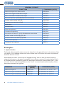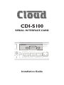
1
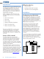
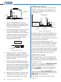
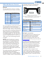
CDI-S100 SERIAL INTERFACE CARD R R L L LINE 5 LINE 6 SERIAL INTERFACE MODULE MUSIC MUTE GAIN 0 -10 dB 10 FUSE 230 230 23 230V 30 RATING + MIC LEFT RIGHT Installation Guide 115V T100mA T100 T100m T200mA POW 2 CDI-S100 Installation Guide v1.0 Contents Introduction....................................................................4 Scope of this manual................................................................................ 4 What’s in the box..................................................................................... 4 Installation......................................................................4 Configuring the CDI-S100...................................................................... 4 Mechanical fitting and internal connection......................................... 5 CX462 jumper settings....................................................................... 6 CX462 switch settings........................................................................ 6 CDI-S100 Remote Control............................................7 Pinout.......................................................................................................... 7 Port parameters........................................................................................ 7 Abridged command set....................................................................... 7 1. Input selection................................................................................... 8 2. Music Level........................................................................................ 9 3. Music Mute/Unmute........................................................................ 9 4. Mute/unmute individual microphones......................................... 9 5. Set master mic level...................................................................... 10 6. Mute/unmute all microphones.................................................... 10 APPENDIX.................................................................. 11 Cable lengths........................................................................................... 11 CDI-S100 Installation Guide v1.0 3 Introduction What’s in the box The CDI-S100 is an optional RS-232C interface card designed specifically for use with the Cloud CX462 Audio System Controller. It allows the CX462 to be controlled by thirdparty systems (such as Crestron, AMX, etc.), using RS-232C serial data. Installation When installed, the CDI-S100 permits the following CX462 functions to be controlled remotely: Configuring the CDI-S100 •• Music source selection •• Music level •• Music muting •• Muting of individual microphones •• Master microphone level •• Master microphone muting Physically, the CDI-S100 is a small printed circuit board (PCB), which is retrofitted internally in the CX462 such that the 9-pin D-type RS-232C connector is available at the rear panel. Scope of this manual This manual describes the mechanical installation of the card and the connections that need to be made to it. It also explains the various configuration options that the card offers, and the various jumper and switch settings that need to be made in the CX462 to achieve correct operation. The manual also gives a general overview of the RS-232C serial control protocol used by the CDI-S100, and some examples of the most useful commands. This information should be adequate for most installations, but please note that a full description of the RS-232C protocol is beyond the scope of this manual. The full protocol can be found at www.cloud.co.uk. •• CDI-S100 PCB •• Installation Guide (this document) •• 2 qty M3 x 25 mm mounting pillars Before installing the CDI-S100 in the CX462, various jumpers on the PCB need to be set correctly. (This step should be performed first because the PCB is installed in the CX462 upside-down, and access to the jumpers is very difficult once it is in position.) The jumpers are concerned with setting the parameters of the serial port (see “Port parameters” on page 7). The port parameters should be set to suit the control system being used. It is quite likely that the factory default settings will provide correct operation; nevertheless, it is important to check that this is so and alter the settings if necessary. To move the jumpers, use small pliers to gently pull the jumper off the header pins and replace in the correct position. Do not use undue force, and do not use pliers which are too big. There are five jumpers, J1 to J5. 4 CDI-S100 Installation Guide v1.0 Baud Rate Jumpers J1 to J3 set the serial port’s baud rate. The default setting is 9600 baud. Check the baud rate of the controlling equipment. If a different baud rate is required, set the jumpers according to the diagram below: DEFAULT SETTING 9600 baud 4800 baud J1 J2 J3 J1 J2 J3 2400 baud 1200 baud J1 J2 J3 J1 J2 J3 300 baud J1 J2 J3 Handshaking RS-232C serial communication between equipment sometimes requires flow control (or “handshaking”), to confirm that transmitter (the controller) and receiver (the CDI-S100 in this case) are correctly synchronised. PCB jumpers J4 and J5 control handshaking. Handshaking may be via “hardware”, “software”, or off. Hardware handshaking is also referred to as “RTS/CTS”, and needs additional pins of the 9-pin serial connector to be wired (see “Pinout” on page 7). Software handshaking is also referred to as “Xon/Xoff”. The default setting is off (no handshaking). If the controlling equipment requires handshaking, set the jumpers according to the following illustration: Mechanical fitting and internal connection If retrofitting the CDI-S100 to an existing CX462 installation, turn the CX462 off, remove its IEC mains lead and all its other rear panel connections (marking as necessary to assist re-connection). If the CX462 is mounted in a rack, remove it. If fitting the CDI-S100 to a new CX462, unpack the CX462. In either case, place the CX462 on a flat surface, with the rear of the unit facing you. 1. Undo the six screws securing the top panel of the CX462; remove the panel. Retain the screws. 2. Remove the plastic blanking plate which covers the serial interface module connector hole in the rear panel. This is held in place with adhesive and can be prised off. 3. Identify the empty 16-pin header labelled CON7 on the main PCB just behind the empty serial connector hole. Note there is an M3 screw immediately behind this connector, and another about 40 mm to the right. Both these screws are clearly marked with arrows; remove and retain them. CDI-S100 Installation Guide v1.0 5 CX462 jumper settings In order for the CDI-S100 to fully control the CX462, it is necessary to correctly set some jumpers on the CX462 main PCB. These are J1 to J4, and J7 to J10. J7 - J10 MUST ALL BE IN THE ‘SW’ POSITION J1 - J4 MUST BE 4. Screw the threaded ends of the two 25 mm mounting pillars supplied with the CDI-S100 into the holes vacated by the screws removed in Step 3. 5. On the CDI-S100 board, remove the two small threaded bushes on the D-type connector; retain them. An M3 nut-driver is the best tool for this. Note that these bushes also retain the metal connector shell – be careful to keep it in place during the next two steps. UNSCREW THESE TWO BUSHES RETAIN METAL SHELL REAR VIEW OF CDI-S100 PCB 6. Plug the connector on the end of the ribbon cable into connector CON7 on the CX462 main PCB. Note it can only be inserted one way round, with the cable exiting to the left. 7. With the CDI-S100 PCB upside-down, insert the D-type connector through the hole in the rear panel.You will see that the two holes at the other end of the PCB are aligned with the mounting pillars fitted in Step 4. Fix the board to the pillars using the screws removed in Step 3. 8. Replace the two bushes removed in Step 5 adjacent to the D-type connector by screwing them through the rear panel. 6 CDI-S100 Installation Guide v1.0 IN PLACE LINE 1 MIC PREAMP PCB J1 J2 J3 J4 GAIN CONTROL REAR EDGE MIC ACCESS REMOTE CONTROL CONNECTOR CONNECTORS OF MAIN PCB LOCATION OF CX-462 JUMPERS LOCATION OF CX-462 JUMPERS Jumpers J1 to J4 are all on 2-pin headers, and can thus be present or absent. They determine how the CX462’s microphone access control operates. When a CDI-S100 PCB is installed, all four jumpers must be present. Jumpers J7 to J10 determine how music source selection and music level are controlled remotely. When an CDI-S100 PCB is installed, all four jumpers must be in the ‘SW’ position. To move the jumpers, use small pliers to gently pull the jumper off the header pins and replace in the correct position. Do not use undue force, and do not use pliers which are too big. CX462 switch settings After the CDI-S100 card has been fitted, and J1 – J4 and J7 – J10 set as described above, the top cover of the CX462 may be replaced, using the original screws. The blue rear panel switch REMOTE TYPE (adjacent to the REMOTE LINE SOURCE/ LEVEL CONTROL connector) should now be set to DIGITAL – i.e., in its ‘in’ position. The front panel LOCAL/REMOTE button (adjacent to the mains switch) should be set to REMOTE (with the LED on). The CX462 is now ready for serial remote control. CDI-S100 Remote Control Pinout handshaking (sometimes called RTS/CTS) requires pins 7 and 8 to be connected. 1 The rear panel serial connector is a female 9-pin Dsub. The pinout is shown in the table: RX 2 RX TX 3 TX 4 5 6 RTS CTS PIN 1 2 3 4 5 6 7 8 9 FUNCTION n/u Data receive Data transmit DTR 0v DSR RTS CTS n/u For most installations, it will only be necessary to connect pins 2, 3 and 5. If the control system’s serial port is also a 9-pin Dsub, use a D9-to-D9 “straight” cable (i.e. one wired with pin 1 to pin 1, pin 2 to pin 2, etc.) If the control system’s serial port is a screw-terminal (or other type of) connector, the terminals will most likely be marked “Tx”, “Rx” and “Gnd”, or something similar. In this case, connect “Tx” to pin 3 on the CDI-S100, “Rx” to Pin 2 and “Gnd” to pin 5. See the following illustration for details. NOTE: Not all manufacturers interpret “Tx” and “Rx” in the same way, and it may be necessary for a “crossed” cable to be used instead. A crossed cable is one with pin 2 connected to pin 3 at the other end, and vice-versa. If your CDI-S100 appears to ignore control system instructions and all connections, programming, etc., appear satisfactory, try reversing pins 2 and 3 at one end of the serial cable. The installer should also check whether the control system being used requires RS-232C flow control (or “handshaking”) to be implemented, and if so, whether hardware control or software control is used. Hardware Connect if hardware flow control is required 7 RTS 8 CTS 9 CDI-S100 CONTROLLER “STRAIGHT” RS-232C SERIAL CABLE Note that some installation require a “crossed” cable in this case, pins 2 and 3 should be reversed at one end. Port parameters PARAMETER VALUE/SETTING Data type: RS-232C serial Data speed 300/1200/2400/4800/9600 baud, selectable by jumper Word length 8 bits Parity None Stop bits One Abridged command set The commands listed in the General Format table (page 8) are those most commonly required. For all other commands, data requests and responses, please refer to the CDI-S100’s full RS-232C protocol document at www.cloud.co.uk. The table provides the general format of each type of command, The commands are given in ASCII form; note that all characters in the command, including the non-alphanumeric ones, must be sent. The characters shown in italics must be replaced by specific numeric values when a command is sent. Following the table, an example of each command type is given; refer to the general format to see how the variable characters are replaced by specific values. The commands in the examples are given in both ASCII and hex form. CDI-S100 Installation Guide v1.0 7 GENERAL FORMAT FUNCTION COMMAND (ASCII) Select Line Input x as music source <MU,SAx/> Select next higher-numbered Line Input <MU,SU/> Select next lower-numbered Line Input <MU,SD/> Set music level to –(m/2) dB relative to max volume <MU,LAm/> Reduce music level by (p/2) dB <MU,LDp/> Increase music level by (q/2) dB <MU,LUq/> Mute music <MU,M/> Unmute music <MU,O/> Mute microphone y <MI.y,M/> Unmute microphone y <MI.y,O/> Set master mic level to –(m/2) dB relative to max volume <MI,LAm/> Reduce master mic level by (p/2) dB <MI,LDp/> Increase master mic level by (q/2) dB <MI,LUq/> Mute all microphones <MI,M/> Unmute all microphones <MI,O/> Examples: 1. Input selection To directly select a specific music source, the value of x in the general format is the number of the Line Input (1 to 6) selected as the music source. Note that x can also be set to zero to positively de-select all music sources. Alternatively, the music sources may be “stepped through” one at a time (in either direction), using the increment or decrement commands. If an increment command is received when Line In 6 is already set, the command is ignored. If a decrement command is received when Line 1 is set, no music source is selected (equivalent to the “Line 0” command mentioned above). Any further decrement commands are ignored Select Line Input 3 COMMAND (ASCII) <MU,SA3/> 3C 4D 55 2C 53 41 33 2F 3E Select Line Input one above current <MU,SU/> 3C 4D 55 2C 53 55 2F 3E Select Line Input one below current <MU,SD/> 3C 4D 55 2C 53 44 2F 3E EXAMPLE 8 CDI-S100 Installation Guide v1.0 COMMAND (HEX) 2. Music Level Levels can either be set to an absolute value (in dBs), or increased/decreased by a specified number of dBs. Adjustment can be made in half-dB steps, and the values m, p and q in the General Format table above represent the number of half-dB steps. For absolute levels, the value of m corresponds to attenuation rather than gain, thus 0 dB is maximum level and at -90 dB the music channel is effectively muted. The value of m in the general format is the attenuation level in half-dBs, and may thus have a value of between 0 and 180. Thus to set the output level to 10 dB below the maximum level, m must be given a value of 20. To alter the music level by a specified amount, the ASCII characters ‘A’ is replaced by ‘U’ (up) or ‘D’ (down) in the string. The value of p or q in the general format is the level increase in half-dB steps (0 to 180), or the level decrease in half-dB steps (0 to 180) respectively. A command to increase the level by a number of dBs greater than the current attenuation will set the level to maximum. Similarly, a command to decrease the level by a number of dBs greater than (90 minus the current attenuation) will mute the music channel. EXAMPLE COMMAND (ASCII) COMMAND (HEX) Set music level to 12 dB below maximum <MU,LA24/> 3C 4D 55 2C 4C 41 32 34 2F 3E Reduce music level by 10 dB <MU,LD20/> 3C 4D 55 2C 4C 44 32 30 2F 3E Increase music level by 6 dB <MU,LU12/> 3C 4D 55 2C 4C 55 31 32 2F 3E 3. Music Mute/Unmute The command strings to mute or unmute the music channel contain no variables, thus the commands given in the General Format table are always applicable. EXAMPLE COMMAND (ASCII) COMMAND (HEX) Mute music channel <MU,M/> 3C 4D 55 2C 4D 2F 3E Unmute music channel <MU,O/> 3C 4D 55 2C 4F 2F 3E 4. Mute/unmute individual microphones Each of the CX462’s four mic inputs may be muted or unmuted individually. The character y in the string represents the number of the mic input, and can have a value of between 1 and 4. EXAMPLE COMMAND (ASCII) COMMAND (HEX) Mute mic input 1 <MI.1,M/> 3C 4D 49 2E 31 2C 4D 2F 3E Unmute mic input 3 <MI.3,O/> 3C 4D 49 2E 33 2C 4F 2F 3E CDI-S100 Installation Guide v1.0 9 5. Set master mic level The strings used to set the master level of the CX462’s microphone channel are the same as those to set the music channel level, except that the character ‘U’ is replaced by ‘I’. As with the music channel, adjustment is in half-dB steps, and the values m, p and q in the General Format table above represent the number of half-dB steps (and are thus double the number of dBs required by the absolute or relative level change). EXAMPLE COMMAND (ASCII) COMMAND (HEX) Set mic level to 20 dB below maximum <MI,LA40/> 3C 4D 49 2C 4C 41 34 30 2F 3E Reduce Mic level by 10 dB <MI,LD20/> 3C 4D 49 2C 4C 44 32 30 2F 3E Increase mic level by 3 dB <MI,LU6/> 3C 4D 49 2C 4C 55 36 2F 3E 6. Mute/unmute all microphones In addition to muting/unmuting the mic inputs individually, the CX462’s microphone channel can be muted at the master stage. The command strings to mute or unmute the mic channel contain no variables, thus the commands given in the General Format table are always applicable. EXAMPLE COMMAND (ASCII) COMMAND (HEX) Mute mic channel <MI,M/> 3C 4D 49 2C 4D 2F 3E Unmute mic channel <MI,O/> 3C 4D 49 2C 4F 2F 3E 10 CDI-S100 Installation Guide v1.0 APPENDIX Cable lengths RS-232C serial communication can use either shielded or unshielded cable. The longest cable run that can be practically used for error-free operation in a given installation will depend on several factors: cable type, the baud rate used and the amount and type of electrical noise present in the cable’s vicinity. A realistic figure for maximum cable length is 250 ft. (76 m.) using good-quality shielded cable and 100 ft. (30 m.) using unshielded cable, at 9600 baud (the most common data rate). However, the figure may be higher or lower in a particular installation. Lowering the baud rate will permit significantly longer cable runs to be used. CDI-S100 Installation Guide v1.0 11 Cloud Electronics Limited 140 Staniforth Road Sheffield S9 3HF England Tel: +44 (0)114 244 7051 Fax: +44 (0)114 242 5462 email: [email protected] web: www.cloud.co.uk