1
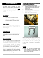
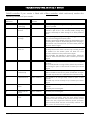
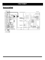
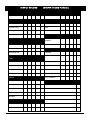
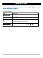
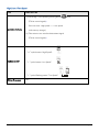
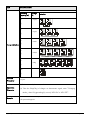
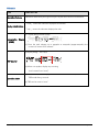
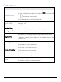
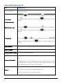
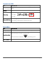
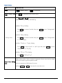
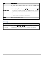
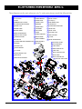
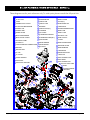
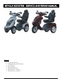
ROYALE SCOOTER – SERVICE AND REPAIR MANUAL Contents: 1. 2. 3. 4. 5. 6. 7. Scooter Maintanence Troubleshooting and Fault Repair Circuit Digram Service Record Display Specifications Parts Reference – Royale 3 Parts Reference – Royale 4 Royale By Drive Service Manual Page 1 SCOOTER MAINTENANCE Your power scooter is designed for minimal maintenance. However, like any motorized vehicle it requires routine maintenance. To keep your scooter for years of trouble-free operation, we recommend you follow the following maintenance checks as scheduled. Warning! Failure to maintain the brushes could void the power scooter warranty. To inspect or replace the motor brushes: 1. Unscrew the motor brush caps (by using a screwdriver on the caps shown by the white arrow). 2. Remove the brushes. 3. Inspect the brushes for wear (replace if less than 9mm) 4. Replace the brushes if necessary. DAILY CHECKS 1. Visual check on the conditions of tyres. 2. Inspect the battery gauge on the display to determine if batteries need to be charged. WEEKLY CHECKS Your scooter comes with standard pneumatic tyres. Make sure to maintain the pressure of the tires between 30-35 psi. Less than 9mm MONTHLY CHECKS Visually inspect the controller harnesses. Make sure that they are not frayed, cut or have any exposed wires. SEMI-ANNUAL CHECKS Check the motor brushes. We recommended that your authorized dealer inspect the brushes every six months or sooner if your power scooter is not operating smoothly. If inspection determines excessive wear on the brushes, they must be replaced or motor damage will result. The brushes should be inspected for wear and colour of the braiding inside the spring. If the braiding is dark brown, red, silver, purple or gold then the brush needs replacing. Royale By Drive Service Manual Inspect the state of the battery terminals every six months. Make sure that they are not corroded and the connections are tight. Periodically apply a thin film of petroleum jelly on the surface of terminals to guard against corrosion. CHECKS: Make sure you keep the controller clean whilst protecting it from rain or water. Never hose off your scooter or place it in direct contact with water. Page 2 Keep wheels free from lint, hair, sand and carpet fibres. Visually inspect the tyre tread. If less than 1mm (1/32”), please have your tyres replaced by your local dealer. All upholstery can be washed with warm water and mild soap. Occasionally check the seat and back for sagging, cuts and tears. Replace if necessary. Do not store your scooter in damp or humid conditions as this will lead to mildew and rapid deterioration of the upholstery parts. Royale By Drive Service Manual All moving mechanisms will benefit from simple lubrication and inspection. Lubricate using petroleum jelly or light oil. Do not use too much oil, otherwise small drips could stain and damage carpets and furnishings etc. Always perform a general inspection of the tightness of all nuts and bolts. ANNUAL SERVICE We recommend the scooter is servicing by annually by your dealer or competent technician. The service schedule is shown on page 6 Page 3 TROUBLESHOOTING AND FAULT REPAIR RHINO controller: If your scooter is fitted with a Rhino controller, which continuously monitors the operating conditions of your scooter. Error Number Reference Fault Impact Scooter 1 Battery needs recharging Will drive Battery charge is running low. Recharge the batteries as soon as possible. 2 Battery voltage too low Drive inhibited Battery charge is empty. Recharge the batteries. If the scooter is left off for a few minutes, battery charge may recover sufficiently to allow driving for a short period of time. 3 Battery voltage too high Drive inhibited Battery charge is too high. If a charger is plugged in, unplug it or turn the Charge/Run switch to Run. Scooters powered by RHINO will charge the batteries when traveling down slopes or decelerating. Excessive charging in this manner may cause this fault. Turn the scooter power off and then back on again. 4 Current limit time out Drive inhibited The scooter has drawn too much current for too long, possibly because the motor has been over worked, jammed or stalled. Turn the scooter power off, leave for a few minutes, and then turn the power back on again. The controller has detected a shorted motor. Check the loom for shorts and check the motor. Contact your service agent. 5 Brake fault Drive inhibited Check that the park brake release lever is in the engaged position. The park brake coil or wiring is faulty. Check the park brake and wiring for open or short circuits. Contact your service agent. 6 Out of Neutral at Power Up Drive inhibited Throttle is not in neutral position when tuning switch key on. Return throttle to neutral, turn power off and back on again. Throttle may need to be re-calibrated Check throttle wiring. 7 Speed Pot Error Drive inhibited The throttle or its wiring is faulty. Check for open or short circuits. Throttle may not be correctly set up. Contact your service agent. 8 Motor Volts Error Drive inhibited The motor or its wiring is faulty. Check for open or short circuits. Contact your service agent. 9 Other Internal Errors Drive inhibited Contact your service agent. 10 Push Too Fast fault Drive inhibited The scooter has been pushed faster than the programmed "Push Speed' parameter when the Park Brake Release function has been operated. The scooter has been pushed faster than the programmed "Rollaway Speed" parameter when the Park Brake has been mechanically released. Turn the scooter off and then back on again. Royale By Drive Service Manual on Notes Page 4 S-DRIVE controller: If your scooter is fitted with a S-Drive controller, which continuously monitors the operating conditions of your scooter. Error Number Reference Fault Impact Scooter on Notes 1 Low Voltage Error flashing The battery requires charging or there is a bad connection to the battery. 2 Motor Connection Scooter will not drive There is a bad connection to the motor. Check all connections between the motor and controller. 3 Short Circuit Scooter will not drive The motor has experienced a short circuit to a battery connection. Check all motor and battery connections. 4 Not Used Not Applicable Not Applicable 5 Not Used Not Applicable Not Applicable 6 Inhibit Scooter will not drive Inhibit circuit has become active not permitting drive. Likely to be caused by a charger being connected or a fault within the controller or wiring. 7 Throttle Fault Scooter will not drive A throttle fault has been indicated. Ensure the throttle is in neutral before switching the scooter on. Throttle may require calibration. 8 Controller Fault Scooter will not drive A controller fault has been indicated. Make sure all connections are secure. Also cycle keyswitch as this fault can be initiated by a break in the circuit during keyswitch initiation. 9 Brake Fault Scooter will not drive There is a fault within the electromagnetic brake circuit, Check all brake and motor connections. Make sure controller connections are secure and that the scooter is not in freewheel mode. 10 Excessive Voltage Scooter will not drive An excessive voltage has been applied to the controller. This is very often caused by a poor battery connection. Check all connections from the batteries to the controller. Note: If you experience any technical problems, it is recommended that you check with your local dealer before attempting to troubleshoot on your own. The following symptoms could indicate a serious problem with your scooter. Contact your local dealer if any of the following arises: 1. 2. 3. 4. 5. 6. 7. 8. 9. Motor noise Frayed harnesses Cracked or broken connectors Uneven wear on any of tires Jerky motion Pulling to one side Bent or broken wheel assemblies Does not power up Powers up, but does not move Royale By Drive Service Manual Page 5 CIRCUIT DIAGRAM Royale 3 and 4 (Rhino) Royale By Drive Service Manual Page 6 SERVICE RECORD YEAR 1 2 3 4 (SHOWN IN USER MANUAL) 5 YEAR Service Dates Service Dates Controller Upholstery On/off switch Seat Control Lever Back Braking Armrests Recharge point Electrics Batteries Connections condition Levels Lights Connections Test run Discharge test Forwards Wheels and Tyres Reverse Wear Emergency stop Pressure Left turn Bearings Right turn Wheel nuts Slope test Motors Over obstacles Wiring List Items repaired 1 2 3 4 5 Noise Connections Brake Brushes Chassis Condition Steering Royale By Drive Service Manual Page 7 DISPLAY SPECIFICATIONS Below is a comprehensive specification and functional manual for the digital display. It is a technical reference guide for dealers and engineers. Speed Sensor and Display ITEM SPECIFICATION Operation Features Speed detection by speed sensor from transaxle with conversion at 1400rpm equal to 60km/h. Tolerance 15~20% ≤ 19.9: 0~19.9 Digits range > 19.9: displayed by integer “20~199” (199 max) Display Switch Button Royale By Drive Service Manual Initial setting at km/h, switch to MPH by MODE and SET buttons Page 8 High / Low / Turn Speed ITEM SPECIFICATION (1) Switch High / Low speed by pressing button once. (TRN as control signals) Press one time: High-speed <<--->> Low-speed Operation Features (with memory storage). (2) Take exterior turn-switch as determinant signal (TRN as control signals). SPEED "H"symbol means “High Speed”: SPEED Symbols on LCD "L"symbol means “Low Speed”: SPEED SPEED "L"symbol flashing means “Turn Speed”: Flicker Frequency Royale By Drive Service Manual 1 sec. Page 9 Power Indication / Battery Gauge ITEM SPECIFICATION Remaining Capacity (%) Voltage (V) Scale Bar 100 > 25.42 (6) 85 ≦ 25.42 (5) 70 ≦ 25.12 (4) Battery Remaining Capacity 55 ≦ 24.78 (3) 40 ≦ 24.42 (2) 30 ≦ 23.88 (1) and 20 Flicker Frequency Operation Characters Low-power Warning Flashing Warning LED Flashing 2 sec. (1) Scale status only decrease, won’t increase. (2) When the remaining capacity was less than 30%, warning sound (“Be-Be” two short sounds) act at 5 seconds intervals. While (a) Key Off (b) Charging Mode (c) Sleep Mode, warning sound released. Royale By Drive Service Manual Page 10 ITEM SPECIFICATION Remaining Capacity (%) Voltage (V) 40 < 25.44 Scale Bar (2) 55 > 25.44 (3) 70 > 26.18 Charge Indication (4) 80 > 26.92 (5) 90 > 28.5 (6) 100 (7) Increase Frequency 0.5 sec. (1) Scale status only decrease, won’t increase. Operation Character (2) Take the PIN3(CH3) of charger as determinant signal, enter「Charging Mode」when CH3 grounding (L), not only “KEY ON” or “KEY OFF”. Remarks Above scale bar status only for reference, must take the indicator of charger as the precise diagnosis. Royale By Drive Service Manual Page 11 Clock ITEM SPECIFICATION Tolerance (per day) ±2 sec. Initial Setting Value 『Hour:Min』mode :『AM 12:00』 Display range : AM12:00 ~ PM11:59 『Hour : Min』Setting (12-Hour format) : A M P M m i l e k m When『Hour』is between 1 and 9 o’clock, displayed at 1~9. Royale By Drive Service Manual Page 12 Odometer ITEM SPECIFICATION Operation Features Odometer detected by the signal of Opto Coupler then converts into distance. 「km/h」 means the odometer displayed as kilometer. Display Switch Button 「mph」 means the odometer displayed as mile. (1) Display Range:00000~99999 : m i l e k m A M P M Accumulative Display [ODO] (2) Once the total mileage up to 99999km or 62149mile (99999÷1.609mile), the counter will restart from “00000”. (1) Display Range:00.0~99.9 : A M P M TRIP Counter m i l e k m (2) When over 99.9km, display stop counting (won’t restart from “00.0”). (1) Odometer indication display on ODO mode when Power On, then switch to TRIP mode after 5 seconds. Operation status (2) TRIP can be reset to “00.0”. Royale By Drive Service Manual Page 13 Headlight Control ITEM SPECIFICATION Take exterior headlight switch as determinant signal. Operation Feature (1) Switch on/off the head light by pressing button turn on/off simultaneously. once, then LED will (2) LCD backlights turn on / turn off with head light. When motor stop, the modulation down to 30% (Headlight) Power Saving Mode When motor act, 100% output power (Headlight) Usage Condition While (a) KEY OFF (b) Power-Saving mode (c) Sleep mode , all functions closed. (1) 2.2V>WIP>2.8V ( 100% Full-power ) Determinant (2) 2.2V<WIP>2.8V ( 100% Full-power ) Condition (3) Full / Half power switch at real time. (4) The determination of “Reversing Mode” need to consider the motor direction and panel setting. (1) Loop Load: 24V/50W max Remarks (2) With “short circuit” and “overload” protection Royale By Drive Service Manual Page 14 Back-up Lamp Control ITEM SPECIFICATION Take exterior back-up lamp switch as determinant signal. (1) Switch on/off the head light by pressing button once, then LED Operation Feature will turn on/off simultaneously. (2) LCD backlights turn on / turn off with head light. (Control Mode) Brake-lamp Mode Reversing-lamp Mode When motor changes from act (go forward) to stop, the lamp reinstated after flashing for 3 sec. Determine as “Reversing Mode”, back-up lamp keep flashing. Reverse warning sound can be set by panel ( Turn on / Turn off) While (a) KEY OFF (b) Charging Mode (c) Sleep Mode, all functions closed. Usage Condition * Brake-lamp & Reversing-lamp Mode won’t be limited by Back-up lamp switch on or off. Flicker Frequency 1 sec. (1) 2.2V>WIP>2.8V ( 50% Half-power ) (2) 2.2V<WIP>2.8V ( 100% Full-power ) Determinant Condition (3) Full / Half power switch at real time. (4) The determination of “Reversing Mode” need to consider the motor direction and panel setting. (1) Loop Load : 24V/50W max Remarks (2) With “short circuit” and “overload” protection Royale By Drive Service Manual Page 15 Indicators and Parking-Lamp Control ITEM Operation Feature SPECIFICATION Take exterior left-right indicators and parking-lamps switch as the determinant signal. Press button Control Mode once, the right-indicator and and flashing, warning sound act. Press indicator. turn off, left-indicator again to turn off left- (Left-direction lamp) (Right-direction lamp) Press button once, the right-indicator and and flashing, warning sound act. Press indicator. (Parking lamp) Press button once, turn off, left-indicator again to turn off left- turn on, right-left indicators and flashing , warning sound act . Press function. again to turn off the Parking lamp Usage Condition While (a) KEY OFF (b) Charging Mode (c) Sleep Mode, all functions closed. Flicker Frequency 1 sec. Warning Sound Frequency One short “Bi” sound per second Left-Right indicators have priority to Parking lamp. <Ex.> Determinant Condition If “Parking lamp” turned on already, now you start “Right indicator” function, the flashing indicator lamps will change from both side (left & right) to right side, and the “Parking lamp” function will be closed. (1) Load circuit for left-direction light: 24V/50W max Remarks (2) Load circuit for right-direction light: 24V/50W max (3) With “short circuit” and “overload” protection Royale By Drive Service Manual Page 16 Malfunction Message / Fault code ITEM SPECIFICATION Take the connector pin (KEY) of controller as determinant signal, then converts it into digital code. Operation Feature When the controller send out an error message, red LED flashing with controller signal at same time, the “Error message code” will show on LCD. Usage Condition mphkm/h Flicker Frequency 1 sec. Controller Message LED message code (Flicker) symbol Status (Flicker) 1 -- -- Battery needs charge soon. 2 2 On Low-voltage, needs charge now 3 3 On Over-voltage 4 4 On 5 5 On 6 6 On 7 7 On Accelerator broken or faulted 8 8 On Motor broken or faulted 9 9 On Others Flashing, opposite controller message. Over-current to Park Brake lost or faulted Accelerator not align center 5-12. Power On Self Test ITEM Initial Status SPECIFICATION When scooter power on, the control panel will go through a self-test routine; the backlight and all LCD segments will be tuned on for 3 seconds, then switch automatically to the general operation mode (ODO). Royale By Drive Service Manual Page 17 Temperature meter (TEMP) ITEM SPECIFICATION Temperature detected by temperature sensor (NTC) from transformation with signal. Operation Feature Tolerance 2C Display Range -20 C ~50 C : A M P M m i l e k m -4 F ~122 F When display C, degree stand for Celsius thermometer Display Switch Button When display F, degree stand for Fahrenheit thermometer Reverse Indicator ITEM SPECIFICATION Operation Feature Take exterior forward / backward switch as determinant signal. When switch direct to “forward”, no symbol on LCD. Power Saving Mode When switch direct to “backward”, Flicker Frequency Royale By Drive Service Manual symbol flashing on LCD. 1 sec. Page 18 Adjust Buttons ITEM SPECIFICATION Button “MODE” switch Function set MOD SET General Display Mode E Press SET for 3 seconds to reset TRIP at “00.0”. (TRIP) Press MODE and SET simultaneously for more than 2 seconds. to enter “Setting Mode”, then 『Hour:MIN』start flashing. (1) When『Hour』flashing: Press SET to increase of number, then press MODE to enter “Setting Mode” of 『MIN』. (2) When『MIN』flashing: Setting Mode Press SET to increase of number, then press MODE to enter “Setting Mode” of 『km/h & mph』. (3) When 『km/h』 or 『mph』flashing Press SET to choose “km/h” or “mph” type, then press .MODE to enter “Setting Mode” of 『 C / F』 (4) When『 C』or『 F』flashing Press SET to choose C or F . Under setting mode, if below situations happened, will auto save the last setting value then escape to general operation mode. Escape from Setting (1) No any operation of ADJ button for 20 sec. Mode (2) Press MODE and SET at same time for more than 2 sec. Royale By Drive Service Manual Page 19 ITEM SPECIFICATION (1) 『Hour:Min』,『km/h』or『mph』,『 C』or『 F』offer Cyclical Switch function. (2) When adjusting 『Hour:Min』, press SET to increase number, if press SET Operation Status for more than 2 seconds, the number will increase continuously until button released, setting value with Cyclical Switch function (only 2 seconds from 0 to 9). * If『Hour』less than 10, the denary “0” doesn’t display.。 Remarks Button tones: one short “Bi” sound LCD Backlight ITEM SPECIFICATION LCD Backlight Royale By Drive Service Manual When pressing MODE and SET buttons, the backlight will be turned on voluntarily and turned off No any operation of ADJ button more than 5 sec. Page 20 BILL OF MATERIALS / PARTS REFERENCE – ROYALE 3 These diagrams are for parts reference only. To order parts, please consult the full parts lists: 1 FRONT TILLER COVER 21 LOCATOR 35 SIDE COVER R 2 TILLER FRAME 22 SPEED METER 36 REAR COVER 3 BUZZER 23 FRONT HUB 37 PLUG(R,L) 4 RUBBER DUST COVER 24 FRONT TYRE 38 DISK BRAKE SET 5 TILLER RAM MECHANISM 25 BEARING 39 TRANSAXLE 6 HANDEL CAP 26 FRONT AXLE 40 SUSPENSION BRACKET 7 HANDEL GRIP 27 CHARGER 41 REAR HUB 8 BRAKE LEVER 28 FR COVER 42 REAR TYRE 9 REAR VIEW MIRROR 29 FORK 43 BATTERY CAP 10 REAR TILLER COVER 30 SPEED SENSOR 44 SIDE COVER L 11 CONTROL PANEL 31 MAIN FRAME 45 FLOOR 12 FR SWITCH 32 REAR FENDER 46 REAR SUSPENSION 13 POTENTIOMETER COMBINATION 33 REAR BASKET 47 RELEASE LEVER 34 BATTERY 14 WIGWAG 48 REAR BUMPER 15 WIGWAG PAD 49 LAMP BASE 16 FRONT BASKET 50 REAR INDICATOR 51 LAMP CAP 17 FF COVER 55 18 FRONT BASKET CAP 52 SEAT SLIDING POST 53 SEAT BASE 19 HEADLIGHT 54 54 SEAT SLIDING RAIL 20 HEADLIGHT BRACKET 55 CAPTAIN SEAT ASM 12 13 15 50 53 11 51 49 14 1 10 52 3 48 27 9 2 47 8 32 7 5 4 6 46 31 39 17 38 16 34 36 37 35 30 18 40 41 33 42 29 20 21 45 22 23 26 19 Royale By Drive Service Manual 24 25 28 43 44 PT7 Page 21 BILL OF MATERIALS / PARTS REFERENCE – ROYALE 4 These diagrams are for parts reference only. To order parts, please consult the full parts lists: 1 FRONT TILLER COVER 21 TURNING COUPLING 35 SIDE COVER R 2 TILLER FRAME 22 SPEED METER 36 REAR COVER 3 BUZZER 23 FRONT HUB 37 PLUG(R,L) 4 RUBBER DUST COVER 24 FRONT TYRE 38 DISK BRAKE SET 5 TILLER RAM MECHANISM 25 BEARING 39 TRANSAXLE 6 HANDEL CAP 26 FRONT AXLE(R,L) 40 SUSPENSION BRACKET 7 HANDEL GRIP 27 CHARGER 41 REAR HUB 8 BRAKE LEVER 28 FR COVER 42 REAR TYRE 9 REAR VIEW MIRROR 29 SUSPENSION SPRING 43 BATTERY CAP 10 REAR TILLER COVER 30 SUSPENSION ARM(R,L) 44 SIDE COVER L 11 CONTROL PANEL 31 MAIN FRAME 45 FLOOR 12 FR SWITCH 32 REAR FENDER 46 REAR SUSPENSION 13 POTENTIOMETER COMBINATION 33 REAR BASKET 47 RELEASE LEVER 34 BATTERY 14 WIGWAG 48 REAR BUMPER 15 WIGWAG PAD 49 LAMP BASE 16 FF CAP 50 REAR INDICATOR 51 LAMP CAP 17 FF COVER 55 18 FRONT BUMPER 52 SEAT SLIDING POST 53 SEAT BASE 19 HEADLIGHT 54 54 SEAT SLIDING RAIL 20 HEADLIGHT BRACKET 55 CAPTAIN SEAT ASM 12 13 15 50 53 11 56 STEM 51 49 14 1 57 FRONT BUMPER BRACKET 10 48 52 3 9 2 47 8 32 5 16 4 27 7 6 46 31 56 39 38 34 36 37 20 40 41 35 29 30 21 42 26 19 25 17 22 18 57 33 23 28 43 24 Royale By Drive Service Manual 45 44 PF7 Page 22