1
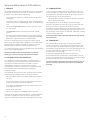
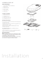
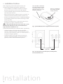
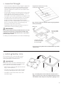
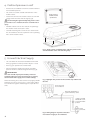
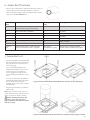
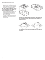
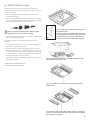
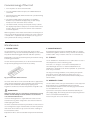
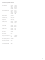
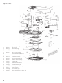
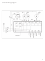
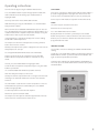
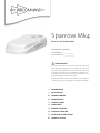
Sparrow Mk4
ROOF TOP AIR CONDITIONER
Model Number: 5860001
Serial Number:
Date Purchased:
WARNING
It is important that this installation manual is properly
read and understood before installation. The unit must
be installed by a qualified service technician. Failure to
properly install the unit or attempting to modify it in
any way can be extremely hazardous and may result in
property damage and personal injury.
Aircommand will not be held responsible for problems
relating to incorrect or improper installation methods.
2
INFORMATION
3
INSTALLATION
10
COMMISSIONING
10
MAINTENANCE
11
SPECIFICATIONS
12
SPARE PARTS
13
WIRING DIAGRAM
14
TROUBLE SHOOTING
15
OPERATING INSTRUCTIONS
16
CONTACT DETAILS
Sparrow MK4 General Information
I. PURPOSE
III. CONDENSATION
The Aircommand Sparrow air conditioning unit is designed for
installation on the roof of a caravan or recreation vehicle to
provide reverse cycle heating and cooling.
In areas of high humidity, the humid air within the van will
cause “sweating” or condensation in parts of the unit as the
humid, warm air contacts the colder air discharge system. If
this occurs please ensure the following:
• The roof must be capable of supporting the weight of the
unit (29kg).
• The mechanisms for raising pop-top roofs must be capable
of operating with the added weight of this air-conditioning
unit.
• The absolute minimum thickness of the roof must not be
less than 25mm.
• The maximum thickness of the roof must not exceed
125mm.
• Closing all doors, hatches, windows and blinds to limit the
ingress of warm humid air.
During operation the air conditioner will remove large
quantities of condensate from the inside air which will drain
onto the van roof. The quantity of condensate will be
dependent on the humidity in the air. Avoid running the inside
fan on LO or AUTO in such conditions. Running the fan on HI
fan speed will result in higher airflow and reduce the tendency
to have condensation form.
• Trimming of the ductwork will be necessary depending on
the roof thickness. You will need to supply longer M8 hold
down bolts if you roof thickness exceeds 85mm.
Aircommand will not be held responsible for damage caused
by condensation.
The unit is not designed to be installed on sleeper cabs of
prime movers although may be suitable in some circumstances.
Warranty will be voided if installed in such circumstances
without the prior approval of Aircommand Australia.
IV. GENERATORS
It is important that the unit is installed properly and according
to the recommended guidelines.
Aircommand will not be held responsible for problems
relating to incorrect or improper installation methods.
II. ENSURING EFFECTIVE OPERATION
The effectiveness of the air conditioner is dependent on
several factors that contribute to the total heat load on the
van. When an Aircommand unit is installed in a van or
motorhome Aircommand assumes that the vehicle
manufacturer or owner has properly assessed the potential
heat load and selected the appropriate capacity airconditioning unit.
The following actions can be taken to reduce peak heat load
and help the air-conditioner deliver the most comfort:
• Closing all doors, hatches, windows and blinds. Extend all
annexes.
• Position the vehicle so that the annex will face north and
protect the windows from direct radiation.
• Turning off unneeded appliances that might increase the
heat load inside the van.
• Cook outside if possible.
• Park the caravan/RV in a shaded position if possible.
In periods of extreme high temperature it is recommended to
start the air conditioner earlier in the morning to greatly
improve its ability to cope with the expected peak heat load.
2
The Sparrow Mk4 is designed to run using mains power,
however many owners may want to use portable generators
to run them when in remote locations. Any generator used
should deliver high quality, pure sine wave, alternating current
at 50Hz, and be able to handle the compressor start up
demand. Given the vast range
in quantity and quality of generators on the market,
Aircommand cannot recommend a specific model or brand.
Discuss your specific requirements with the generator supplier
directly and consider their recommendations.
Aircommand will not be held responsible for damages due to
the use of improper generators and such use may void your
warranty.
Installation Parts List
MAIN COMPONENTS
1
Sparrow Mk4 rooftop air conditioner
1
2 Weather collar
3
Black plastic duct
4 Brace assembly
5
Plenum filters x 2
6 Plenum cover
2
FITTINGS & FIXTURES
7
M8x120mm bolts x 4
8 Hold down bars x 4
3
9 Plenum cover screws x 4
10 Self tapping screws x 6
4
BEFORE INSTALLATION
Ensure that the installation instructions have been properly
read and understood.
5
Installation must confirm to nation wiring regulations and
in particular AS3001 – 2008.
DO NOT attempt to modify or add components to the
installation procedure.
5
6
This equipment must only be serviced by a licensed
refrigeration mechanic.
If your installation varies from the method outlined please
contact Aircommand for specialty advice.
7
8
9
10
WARNING
Failure to properly install the unit or attempting to modify
it in any way can be extremely hazardous and may result in
property damage and/or personal injury.
Aircommand will not be held responsible for issues arising
from incorrect or improper installation methods.
Installation
3
1. Installation Position
Before beginning, mark out the position of the unit
considering the following important requirements:
• The air conditioner should be situated as centrally as
possible on the van, to ensure even air distribution.
There should be a minimum
of 100mm clearance around
the perimeter of the unit to
allow for service access and
air flow to condenser.
Hot air is ejected from
this exhaust; consider
nearby roof hatch.
• The Sparrow Mk4 may be oriented in any direction to the
normal direction of travel.
• When considering the installation position remember to
check for clearance around the plenum inside the van.
• Avoid an installation position where a bulkhead, cupboard
or light fitting could interfere with the discharge air flow
from the plenum.
• Avoid an installation where a roof joining seam crosses
through the 14” square installation cut out.
It is important that the unit is never more than 5° from
the horizontal and the rear of the unit should never be
higher than the front when in use.
Fig 1: Sparrow Mk4 clearances required around roof top unit.
Contact Aircommand if your installation differs significantly.
• The above outline on the left shows the minimum
clearance required around the Sparrow Mk4 unit on the
roof of the vehicle, distances shown are calculated from a
14” square hole (356 x 356mm).
• The above outline on the right shows the minimum
clearance required around the 14” square hole (356 x
356mm) in order to accommodate the plenum.
14” x 14” (356mm)
square hole
Fig 2: The foot print of the rooftop unit, and the plenum,
measured from the hole.
Installation
4
2. Assess Roof Strength
• The roof members MUST be strong enough to support the
weight of the unit without any roof deflection that will
cause “pooling” of water around the unit. Contact your
caravan manufacturer to confirm the max load the roof is
able to handle.
Longitudinals must be fixed securely
to transverse roof members
• If the roof does not have an existing hole one must be cut.
Cut through the roof then use the roof hole as a guide to
cut through the ceiling. Contact your caravan
manufacturer for the best method to cut through the roof.
• The square hole in the roof (356 x 356mm, 14” x 14”) MUST
be boxed up with minimum 20mm square timber to
provide a structure strong enough to withstand the
compression of the installation bolts. This is also to ensure
that air in not drawn from the roof cavity (Fig 3 & 4).
Remember to leave access for wiring.
• Longitudinals MUST be fixed securely to the transverse
roof members to transfer load (Fig 3 & 4).
Fig 3: Shows an ideal roof structure with strong longitudinals
and a 14’ hole boxed.
20mm min
WARNING
There may be electrical wiring located between the roof and
ceiling. Ensure that power is properly disconnected at the
supply (mains and/or battery). Failure to do so may result in
personal injury or death.
Be sure to allow
space for power
cable.
TIP: Always use crawl boards across the roof to avoid damage.
The roof cavity must
be framed to support
the units weight.
Fig 4: The roof cavity MUST be boxed with timber to provide a
solid structure.
3. Installing Weather Collar
Ensure that the roof is clean, dry and free from
grease or oil and that there are no roof seams
running through the installation area.
IMPORTANT
The weather collar must be assembled to the roof
top the right way up. Check the orientation of the
part. Look for the ‘THIS SIDE UP STICKER’.
Apply sealant to
this underside
face only.
• Apply silicone sealant to underside face of collar
(Fig 5 – left hand picture).
• Turn collar over, make sure ‘THIS SIDE UP’ sticker
is facing up and apply the collar to the 14” hole.
• Push down on collar and remove excess from
around the edges.
Fig 5: Left hand picture shows underside of weather collar –
apply sealant across this entire face. Right hand picture shows
‘THIS SIDE UP’ sticker. Keep this side up when applying to roof.
5
4. Position Sparrow on roof
• Remove the air conditioner from the carton and move
to installation position.
• Put a circle of sealant around each bolt hole in the
weather collar.
Apply circle of
sealant around
4 bolt holes.
• Position the unit over the weather collar. The unit will
engage with the collar and self-align (Fig 6).
The unit weights approximately 28kg. Ensure a two
person lift or use a mechanical hoist to avoid the risk of
injury.
• DO NOT slide the unit on the roof, this may damage
the weather collar and result in leaks.
• Four M8 mounting holes on the chassis underneath
the air conditioner will line up with the corresponding
holes on the weather collar.
Fig 6: Apply sealant around bolt holes and then position unit
over the weather collar and set down gently.
5. Connect Electrical Supply
• This unit MUST be installed in accordance with SAA
Wiring regulations and in particular AS3001 – 2008.
• Refer Fig 7 for position of terminal block.
• Connect electrical supply to terminal strip. Note
position of active, neutral and ground wires (Fig 8).
WARNING
This work should only be performed by a licenced
electrical tradesperson. Ensure that power is properly
disconnected at the supply (mains and/or battery).
When connecting wires into terminal strip apply suitable
clamping pressure to ensure wire is secure while taking
care not to over tighten and damage the exposed wire
ends.
Fig 7: Highlights the position of the terminal strip underneath
the unit.
Connection block
at air conditioner
N
A
Rigid cable minimum area
1.5 mm2 minimum 7 strand
Brown
Blue
Y&G
15 Amp 2 pole RCD
Minumum contact
gap of 3mm in OFF
position
15 Amp
power inlet
Fig 8: Wiring diagram of power connection
from external supply to air conditioner.
6
6. Assess Roof Thickness
• Measure the roof thickness and consult the table across to
check if adjustments to the duct length are required.
• NOTE: If the duct length needs to be adjusted then cut the
excess from the un-notched end.
Roof thickness
(mm)
Comment
Duct length
(mm)
Bolt length
25
Absolute minimum – ring must be
removed from top of plenum ducting.
60
Standard
30
Use plenum duct as provided
65
Standard
40
“
75
Standard
50
“
85
Standard
60
“
95
Standard
85
“
120
Limit of std bolt
115
Absolute maximum
150
Installer to provide
General
rule
Roof less than 30mm – remove duct ring.
30mm or thicker leave duct as supplied
Duct length =
Roof thickness + 35mm
Roof greater than 85mm thick will
require installer to provide longer bolts
7. Assemble Duct
• Thread a hold down bar onto the M8
bolt and push the bolt almost all the
way into the hole in each corner of
the brace (Fig 9).
• Leave a 10mm gap between the
hold down bar and the recess in the
plastic brace. This will allow for
easier engagement with the four
corresponding threaded holes in the
unit.
• Turn the assembly over and add the
black plastic duct work to the top of
the assembly with the notch
upwards (Fig 10). The notch is shown
circled below.
Fig 9: Insert the four M8 bolts and hold down bars into the corners of the brace.
• Align the notch with the inside fans
power cable.
Note: Some installers find it easier to
attach the duct to the roof top unit first
and then insert the brace assembly.
When attaching the duct to the
unit take care to ensure it forms a
tight, unbroken seal that doesn’t allow
cold air to escape.
Fig 10: Fit the black plastic duct onto the brace assembly ensuring a tight, sealed fit.
7
8. Attach Duct to Unit
• Raise the brace assembly and slip the black
plastic duct over the outside of the fan
outlet underneath the rooftop unit. Ensure
that the notch cut in the plastic ductwork
aligns with the fans power cable (Fig 12).
When attaching the duct to the unit take
care to ensure it forms a tight, unbroken seal
that doesn’t allow cold air to escape.
• Engage and tighten the four M8 bolts with
the threaded inserts in the rooftop unit.
• Recommended tightening torque of the
bolts is 7 N.m (5.2 lbf-ft).
• As the bolts are tightened ensure that the
hold down bars slot into their recesses in
the brace (Fig 11).
Fig 11: Raise the duct assembly up to the roof hole, ensuring the black plastic
duct work forms a tight fit around the evaporator fan underneath the unit.
Then engage the four M8 bolts, taking care to ensure the hold down bars
slot into their recesses.
Fig 12: Highlights how the notch on the plastic duct slots over the wire from
the inside fan.
8
9. Attach Plenum Cover
Connect the main cover of the plenum to the duct by
attaching the blue suspension cord to the lug on the inside
of the cover (Fig 13).
• This will allow you to use two hands to connect the
control cable (Fig 14).
• Connect the key pad control cables together (see below).
Be sure that the plug joins the corresponding wire colours
together (yellow to yellow, red to red etc).
Failure to properly plug the control cables together
correctly will result in loss of power to display.
• Secure the main plenum cover to the duct assembly with
the 4 screws provided (Fig 15).
Fig 13: Shows the positioning of the lug inside
the plenum cover.
Pull the suspension cord down from inside the
unit and hook it through the lug shown inside
the plenum housing. This will allow two free
hands to connect the control cables together.
TIP: Remove the filters to make hole alignment easier.
(Fig 16).
• It is important that these screws are not over tightened
otherwise the plenum may crack.
• Remove the filter elements by pulling them out of the
plenum, and use the six self tapping counter sunk screws
to secure the cover’s edges to the caravan ceiling (Fig 16).
In some instances a very small pilot hole may need to be
drilled to guide the screws into place.
• Replace the filters by sliding them into the plenum until
they click into place.
Fig 14: Attaching the suspension cable will allow two hands
free to plug in the control cable.
INSTALLATION IS NOW COMPLETE.
PROCEED TO COMMISSIONING.
Fig 15: Secure the main plenum cover to the duct assembly
with the four.
Fig 16: Remove the plenum filters and use the six self tapping
screws to secure the plenum over to the ceiling of the caravan.
Be sure not to over tighten.
9
Commissioning of the Unit
1. Turn the power on at the circuit breaker.
2. Press the ON/OFF button and press the MODE button to
select FAN.
3. Cycle through the LOW, MED and HIGH fan speeds checking
that all speeds run.
4. Set mode to COOL, adjust temperature via up/down
buttons to 4˚C below the display temp (ie room temp)
compressor will start within three minutes.
5. Set mode to HEAT, similarly set temperature to 4˚C above
the display temperature. Compressor will start within three
minutes. After a few minutes the fan will start and warm
air will be apparent.
NOTE: Regardless of the mode selected there will always be at
least a 3 minute delay before the compressor starts. If the unit
is turned off it is important that the compressor be given at
least 3 minutes before being re-activated
Maintenance
I. PLENUM FILTERS
II. MOUNTING BOLTS
The plenum filters are the only parts that require routine
maintenance. They must be cleaned periodically to ensure that
they do not become clogged with dust and other particles.
Aircommand suggests that the hold down bolts are initially
checked for tightness within the first 3 months of installation,
and thereafter every 12 months if the van is in constant use.
Blocked filters must be cleaned frequently to maintain cooling
& heating performance
III. STORAGE
To clean the two plenum filters, first remove them both from
the plenum by pulling them out of the assembly.
The air conditioner should be run on a routine basis to ensure
the components remain in working order.
If the van is in storage or is to remain unoccupied for an
extended length of time it is recommended that the air
conditioner is allowed to run uninterrupted for 20-30 minutes
once every six months.
Fig 17: Plenum filter when removed.
The state of the filters can be ascertained from its appearance,
if they appear clogged then they should be cleaned. Generally
the filters can be cleaned sufficiently by tapping them
together to shake loose the dust and particles trapped inside.
WARNING
Airborne particles can pose a health risk, particulalry to young
children and the elderly. Ensure that filters are cleaned in a
safe and well ventilated area.
If a more thorough clean is required then the filters can be
washed out using warm soapy water. Care must be taken to
avoid ripping the fabric.
The filters should be cleaned every two weeks or more when in
use. Prolonged use, higher concentrations of airborne particles
and various other factors may result in the filters needing to
be cleaned more often.
Replacement filters can be ordered directly from Aircommand.
10
For long term storage outdoors, or to protect your Sparrow
from winter storms and weathering when not in use, a
protective cover can be purchased from Aircommand, please
call for details.
IV. WARRANTY CLAIMS
The unit comes with a one year manufacturer’s warranty from
date of purchase. It is IMPORTANT that you read and
understand the conditions of the warranty agreement which
are included with the unit.
If you have a claim please contact Aircommand directly on
(+61) 8 8345 8444, alternatively you can fax (+61) 8243 0628 or
email [email protected]
Please have your unit serial number ready.
General Specifications
Air conditioner
Air discharge plenum
height
width
205mm
560mm
length
975mm
weight
26.6kg
height
65mm
width
535mm
length
555mm
weight
2.4kg
Model number
5860001
Electrical rating
240V, 50Hz
Refrigerant
407C, 450g
Rated capacity
cooling
2000W
heating
2150W
cooling
920W
heating
930W
cooling
3.9A
heating
4.0A
Power input
Rated current
Max input
1020W
Max current
4.4A
Design system pressure
hi
2900kPa
low
1840kPa
Max operating pressure
2400kPa
Air delivery maximum
110l/s
Total installed weight
29kg
11
Spare Parts
REFERENCE
DESCRIPTION
1
5862022
Top housing fitting kit
2
5862001
Top housing
3
5862033
Bottom housing
4
5862015
Inside fan EPS housing
5
5861010
Outside fan assembly
6
Refer to Aircommand service
7
5861006
Electrical kit
8
5862010
Inside fan assembly
9
5861002
Consensate collector set
10
5861001
Weather collar assembly
11
8001012
Circullar duct
12
8002031
Combined duct & brace
13
8002037
Installation fittings kit
14
5852006
Sparrow plenum assembly
15
5601051
Remote control
16
8002044
Plenum filters, pair
17
5603035
Louvre replacement set (6 per set)
12
Schematic Wiring Diagram
13
Troubleshooting
It is important that any work performed on this unit is
carried out by a qualified service technician. Work by an
unqualified technician can be extremely hazardous and
may result in property damage and/or personal injury.
When attempting to diagnose a fault through our service
department please have the answers to as many of the
following questions as possible:
This Aircommand air conditioner will display an error code
on the control panel when it senses a fault. The error codes
shown below are for reference purposes only. When your
unit displays any of these codes we suggest you contact
Aircommand Australia or an authorised service agent for
assistance.
2. Does the display board appear normal?
E1: ROOM SENSOR FAULT
5. Is the display showing an unusual figure?
Possibly a faulty connection (plug), damaged lead or a faulty
sensor itself.
1. Is there, or have there been, any error codes displayed?
Are temperatures displayed from 16 to 30OC?
3. In heating or cooling modes can the temperatures be
altered via the up/down buttons from 16 to 30OC?
4. Is the display showing ‘0’?
6. When the unit is set to ‘FAN’ only, does the inside fan have
3 speeds?
Does the inside fan blow air?
E2: INSIDE COIL SENSOR FAULT
Possibly a faulty connection (2 plugs), damaged lead or faulty
sensor.
E3: OUTSIDE COIL SENSOR FAULT
Possibly a faulty connection (2 plugs), damaged lead or faulty
sensor.
E4: INDICATES LACK OF REFRIGERANT BEING PUMPED
THROUGH THE SYSTEM
Possibly gas leaked from system through severed/cracked pipe,
or the compressor is not running or the thermistor is out of
calibration.
E5: INDICATES EXCESSIVE TEMPERATURE
Excessive temperature of the outside coil if on cooling, or
excessive temperature of the inside coil in heat mode.
On cooling, the E5 will appear if the outside coil temperature
exceeds 68OC. This is an indication of condenser airflow
reduced or non-existent or condensor fan not working
sufficiently or the thermistor is out of calibration.
NB: When in heat mode, at outside temperatures above 18OC,
the outside fan motors may cycle on and off.
This is the system-shedding load to avoid overheating the
inside coil and is not a fault.
E6 & E7 ARE NOT UTILISED IN THIS SYSTEM.
If either of these codes appear, the main control board needs
to be replaced.
14
7. Can the compressor be heard running?
If the unit is being operated on a generator, a ‘0’ or any other
unusual display occurs, this indicates a problem with the sine
wave ouput from the generator assuming the unit is OK on
mains power.
Operating instructions
Turn the unit on by pressing the ON/OFF button once.
Press the MODE button to cycle through options COOL, DRY,
HEAT and FAN. To select cooling, cycle mode button to
highlight COOL.
SLEEP MODE:
lf the unit is operating in COOL mode and the SLEEP button is
pressed to highlight the Sleep light, then the unit over the
next one hour will automatically raise the set point by 1oC.
Conversely in HEAT mode, the setpoint will be lowered 1oC.
You may select either HIGH, MED, LOW or AUTO
FAN SPEEDS by pressing the FAN button. It is recommended
that you choose AUTO.
Now select the desired ROOM TEMPERATURE (herein referred
to as SETPOINT) by pressing the TEMP up or down buttons. The
readout will flash the setpoint temperature. Keep pressing the
button until it flashes your desired setpoint.
In approximately 5 seconds the display will resume reading
the ACTUAL room temperature.
TIMER:
The Timer may be used to turn the unit
ON or OFF in the next 24 hours.
Press the TIMER button once and the
display will flash. Then within 3 seconds press the TIMER
button until you have set desired time to turn the unit OFF.
Another press of the timer button will allow the unit to be
programmed to turn ON.
The compressor will have a delayed start, usually 3 minutes
before the unit starts to cool.
NB: Any interruption to the power supply will cause the unit to
delay compressor start up.
For simply RECIRCULATING AIR, choose the FAN mode.
Choose any of the three fan speeds by pressing the FAN
button. NB: The temperature button is invalid in Fan only
mode.
To heat, press the MODE button to highlight HEAT.
Select the desired setpoint temperature by pressing the TEMP
buttons up or down.
LOCKING FUCTlON:
This provides a means of locking the MODE and FAN SPEED
setting.
To lock, press the TEMP down button simultaneously with the
MODE button. Hold for 3 seconds and the lock indicator will
light. To unlock repeat above procedure.
To change the readout from CENTIGRADE to FAHRENHEIT or
vice versa, press the TEMP down button simultaneously with
the FAN button.
It is recommended that AUTO fan speed be selected.
After the delay, the compressor will start.
Usually the fan will stop and will not re-energize until the heat
exchanger has warmed and then the fan will start to blow
warm air.
The DRY mode is used when the room temperature is close to
comfortable but you wish to dehumidify. Press the MODE
button to highlight DRY.
Set the temperature to the desired setpoint.
NB: The fan speed is locked in LOW.
The compressor will cycle on and off at approximate intervals
of 6 minutes to extract moisture from the air.
15
Contact details
AIRCOMMAND AUSTRALIA
954 Port Road
Albert Park
South Australia 5014
Australia
Phone: (+61) 8 8345 8444
Fax: (+61) 8 8243 0628
AIRCOMMAND EUROPE
Locke Leisure Products
The Gables, Stoneleigh Road
Bubbenhall
Coventry CV8 3BT
United Kingdom
Phone: (+44) 2476 303 380
For sales enquiries please email:
[email protected]
For warranty, service or technical
enquiries please email:
[email protected]
For spare parts enquiries please email:
[email protected]
16