1
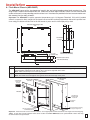
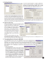
TECHNICAL
Practice
Practice
TELECOM SOLUTIONS
AES-2005
Accessible Entry System
with Color Video Camera
2 1 S T C E N T U RY
FOR THE
September 15, 2014
Apartment Entry System with Accessibility
Features and Color Video
The AES-2005 Accessible Entry System provides both audio and
visual assistance for those with disabilities, two-way handsfree
audio communication and color composite video of who is at
your door or gate entrance.
The LCD display with large 1/2” tall characters is back-lit and will
display a directory of tenants as well as directions and prompts.
A built in voice recorder and announcer can also provide a supporting audio message. When the EZ™ Access button is
pressed, instructions on how to use the system are both displayed and announced.
The built in directory can support up to 525 tenant names and
phone numbers and will dial a pre-programmed phone number
upon selection of a tenant. Once two-way communication has been established, the tenant can activate
a remote door strike by entering a Touch Tone command. A second relay is also provided to operate an
automatic door. The AES-2005 will also support keyless entry at the door via its built-in keypad, or by
adding Wiegand-type proximity card readers, such as the Viking PRX-1, PRX-2, PRX-3 or PRX-4.
AES-2005S Surface Mount
The unit is available in flush (AES-2005F) and surface mount (AES-2005S shown) configurations and features a highly vandal resistant housing.
Note: This unit requires a PB-100 for programming.
Features
Applications
• Built-in high resolution color video camera with wide viewing
angle, tilt/swivel adjustments and wide operating temperature
• 16 position, back-lit display with 1/2” tall characters
• Non-volatile digital voice announcer
• Factory configured to voice announce the names for 75
apartments (expandable to 525 apartments using ERAM-4M
expansion kits)
• Non-volatile data memory for names, phone numbers
and access codes
• Volume control
• AES-NET card reader interface now included
• TTY jack for connection to personal teletypewriter (TTY)
• Postal lock switch input
• Available in surface mount (AES-2005S) or flush mount
(AES-2005F) configurations
• Keyless entry capability
• 5 Amp door strike/magnetic lock control relays
• Vandal resistant features:
- 12 gauge stainless steel front panel
- 1/4” thick abrasion resistant polycarbonate display lens
- Metal keypad and push button switches
- Front panel lock
- Speaker protection screen
• Weather resistant features:
- Enamel coated circuit board
- Gasketing behind lens, speaker, keypad and perimeter
of front panel
- Sealed switches and keypad
•
•
•
•
•
•
•
High rise apartment buildings
Condos
Senior citizen buildings
Assisted care centers
Retirement homes
Gated communities
Use with Viking PRX-1 (DOD# 221), PRX-2 (DOD# 219),
PRX-3 (DOD# 228) or PRX-4 (DOD# 199) Proximity Card
Readers
Specifications
Power: 120V AC/13.8V AC 1.25A, UL listed adapter provided
Dimensions: AES-2005S (Surface mount): 317.5mm x
247.6mm x 107.9mm (12.5" x 9.75" x 4.25"), AES-2005F (Flush
mount): 381mm x 317.5mm x 88.9mm (15" x 12.5" x 3.5")
Shipping Weight: 7.7kg (17 lbs)
Environmental: -26° C to 54° C (-15° F to 130° F) with 5% to
95% non-condensing humidity (see Installation for details)
Display: 16 position, 0.5” x 4.25” back-lit LCD
Relay Contacts: 5A @ 30V DC/250V AC max.
Connections: (20) cage clamp screw terminals, 3 gel-filled butt
connectors (3M Scotchlok UR2)
Maximum Wiegand Length (24 AWG wire): PRX-1: 244m (800
ft), PRX-2: 122m (400 ft), PRX-3 (using 3 pairs for power): 244m
(800 ft), PRX-4: 244m (800 ft)
(See page 2 for camera specifications)
IF YOU HAVE A PROBLEM WITH A VIKING PRODUCT, PLEASE CONTACT: VIKING TECHNICAL SUPPORT AT (715) 386-8666
Our Technical Support Department is available for assistance Monday 8am - 4pm and Tuesday through Friday 8am - 5pm central time. So that we can give you better service, before you call please:
1. Know the model number, the serial number and what software version you have (see serial label).
2. Have your Technical Practice in front of you.
3. It is best if you are on site.
RETURNING PRODUCT FOR REPAIR
RETURNING PRODUCT FOR EXCHANGE
The following procedure is for equipment that needs repair:
1. Customer must contact Viking's Technical Support Department at 715-386-8666 to obtain a Return Authorization (RA)
number. The customer MUST have a complete description of the problem, with all pertinent information regarding the
defect, such as options set, conditions, symptoms, methods to duplicate problem, frequency of failure, etc.
2. Packing: Return equipment in original box or in proper packing so that damage will not occur while in transit. Static
sensitive equipment such as a circuit board should be in an anti-static bag, sandwiched between foam and individually boxed. All equipment should be wrapped to avoid packing material lodging in or sticking to the equipment. Include
ALL parts of the equipment. C.O.D. or freight collect shipments cannot be accepted. Ship cartons prepaid to:
Viking Electronics, 1531 Industrial Street, Hudson, WI 54016
3. Return shipping address: Be sure to include your return shipping address inside the box. We cannot ship to a PO Box.
4. RA number on carton: In large printing, write the R.A. number on the outside of each carton being returned.
The following procedure is for equipment that has failed out-of-box (within 10 days of purchase):
1. Customer must contact Viking’s Technical Support at 715-386-8666 to determine possible causes for the problem. The
customer MUST be able to step through recommended tests for diagnosis.
2. If the Technical Support Product Specialist determines that the equipment is defective based on the customer's input
and troubleshooting, a Return Authorization (R.A.) number will be issued. This number is valid for fourteen (14)
calendar days from the date of issue.
3. After obtaining the R.A. number, return the approved equipment to your distributor, referencing the R.A. number. Your
distributor will then replace the product over the counter at no charge. The distributor will then return the product to
Viking using the same R.A. number.
4. The distributor will NOT exchange this product without first obtaining the R.A. number from you. If you haven't
followed the steps listed in 1, 2 and 3, be aware that you will have to pay a restocking charge.
TWO YEAR LIMITED WARRANTY
Viking warrants its products to be free from defects in the workmanship or materials, under normal use and service, for a period of two years from the date of purchase from any authorized Viking distributor. If at any time during the warranty
period, the product is deemed defective or malfunctions, return the product to Viking Electronics, Inc., 1531 Industrial Street, Hudson, WI., 54016. Customer must contact Viking's Technical Support Department at 715-386-8666 to obtain a Return
Authorization (R.A.) number.
This warranty does not cover any damage to the product due to lightning, over voltage, under voltage, accident, misuse, abuse, negligence or any damage caused by use of the product by the purchaser or others. This warranty does not cover
non-EWP products that have been exposed to wet or corrosive environments. This warranty does not cover stainless steel surfaces that have not been properly maintained.
NO OTHER WARRANTIES. VIKING MAKES NO WARRANTIES RELATING TO ITS PRODUCTS OTHER THAN AS DESCRIBED ABOVE AND DISCLAIMS ANY EXPRESS OR IMPLIED WARRANTIES OR MERCHANTABILITY OR FITNESS
FOR ANY PARTICULAR PURPOSE.
EXCLUSION OF CONSEQUENTIAL DAMAGES. VIKING SHALL NOT, UNDER ANY CIRCUMSTANCES, BE LIABLE TO PURCHASER, OR ANY OTHER PARTY, FOR CONSEQUENTIAL, INCIDENTAL, SPECIAL OR EXEMPLARY DAMAGES
ARISING OUT OF OR RELATED TO THE SALE OR USE OF THE PRODUCT SOLD HEREUNDER.
EXCLUSIVE REMEDY AND LIMITATION OF LIABILITY. WHETHER IN AN ACTION BASED ON CONTRACT, TORT (INCLUDING NEGLIGENCE OR STRICT LIABILITY) OR ANY OTHER LEGAL THEORY, ANY LIABILITY OF VIKING SHALL
BE LIMITED TO REPAIR OR REPLACEMENT OF THE PRODUCT, OR AT VIKING'S OPTION, REFUND OF THE PURCHASE PRICE AS THE EXCLUSIVE REMEDY AND ANY LIABILITY OF VIKING SHALL BE SO LIMITED.
IT IS EXPRESSLY UNDERSTOOD AND AGREED THAT EACH AND EVERY PROVISION OF THIS AGREEMENT WHICH PROVIDES FOR DISCLAIMER OF WARRANTIES, EXCLUSION OF CONSEQUENTIAL DAMAGES, AND EXCLUSIVE REMEDY AND LIMITATION OF LIABILITY, ARE SEVERABLE FROM ANY OTHER PROVISION AND EACH PROVISION IS A SEPARABLE AND INDEPENDENT ELEMENT OF RISK ALLOCATION AND IS INTENDED TO BE ENFORCED
AS SUCH.
FCC REQUIREMENTS
This equipment complies with Part 68 of the FCC rules and the requirements adopted by the ACTA. Inside the front panel
of this equipment is a label that contains, among other information, a product identifier in the format US:AAAEQ##TXXXX.
If requested, this number must be provided to the telephone company.
The REN is used to determine the number of devices that may be connected to a telephone line. Excessive REN's on a
telephone line may result in the devices not ringing in response to an incoming call. In most but not all areas, the sum of
the REN's should not exceed five (5.0) To be certain of the number of devices that may be connected to a line, as determined by the total REN's, contact the local telephone company. For products approved after July 23, 2001, the REN for
this product is part of the product identifier that has the format US:AAAEQ##TXXXX. The digits represented by ## are the
REN without a decimal point (e.g., 03 is a REN of 0.3). For earlier products, the REN is separately shown on the label.
The plug used to connect this equipment to the premises wiring and telephone network must comply with the applicable
FCC Part 68 rules and requirements adopted by the ACTA. If your home has specially wired alarm equipment connected
to the telephone line, ensure the installation of this AES-2005 does not disable your alarm equipment. If you have questions about what will disable alarm equipment, consult your telephone company or a qualified installer.
If the AES-2005 causes harm to the telephone network, the telephone company will notify you in advance that temporary
discontinuance of service may be required. But if advance notice isn't practical, the telephone company will notify the customer as soon as possible. Also, you will be advised of your right to file a complaint with the FCC if you believe it is necessary.
The telephone company may make changes in its facilities, equipment, operations, or procedures that could affect the
operation of the equipment. If this happens, the telephone company will provide advance notice in order for you to make
the necessary modifications to maintain uninterrupted service.
If trouble is experienced with the AES-2005, for repair or warranty information, please contact:
Viking Electronics, Inc., 1531 Industrial Street, Hudson, WI 54016 (715) 386-8666
If the equipment is causing harm to the telephone network, the telephone company may request that you disconnect the
equipment until the problem is resolved.
Connection to Party Line Service is subject to State Tariffs. Contact the state public utility commission, public service commission or corporation commission for information.
WHEN PROGRAMMING EMERGENCY NUMBERS AND (OR) MAKING TEST CALLS TO EMERGENCY NUMBERS:
Remain on the line and briefly explain to the dispatcher the reason for the call. Perform such activities in the off-peak
hours, such as early morning or late evenings.
It is recommended that the customer install an AC surge arrester in the AC outlet to which this device is connected. This
is to avoid damaging the equipment caused by local lightning strikes and other electrical surges.
PART 15 LIMITATIONS
This equipment has been tested and found to comply with the limits for a Class A digital device, pursuant to Part 15 of the
FCC Rules. These limits are designed to provide reasonable protection against harmful interference when the equipment
is operated in a commercial environment. This equipment generates, uses, and can radiate radio frequency energy and,
if not installed and used in accordance with the instruction manual, may cause harmful interference to radio communications. Operation of this equipment in a residential area is likely to cause harmful interference in which case the user will
be required to correct the interference at his own expense.
Specifications
Camera Specifications
Power: 6-22V DC 150mA (12V DC UL Listed adapter included)
Image Sensor: 1/4” color CMOS
Video Output: 1 VP-P composite, NTSC, 75 ohms
Resolution: 420 lines (640 x 480 @ 30fps / 307,200 pixels)
Sensitivity: 0.025 LUX (50 IRE) F 1.2 3200K
Lens: 2.1mm, conical pinhole
FOV (Field of View): 80°, Horizontal, 60° Vertcal, 100° Diagonal
Tilt/Swivel Adjustment: Vertical +/- 20°, horizontal +/- 30° (see Diagram A)
IR Compatibility: This camera is equipped with an OLP (Optical Low Pass) filter
to maintain correct video color in outside applications. The standard camera is NOT
compatible with IR illuminators. If IR illumination is required, you will need to
replace the exisiting camera with a Viking model VCAM-1IR. For more information,
see DOD# 190.
Maximum Wire Run Length: 1000 ft with *RG59/RG6 for video and CAT5 for
power (single pair) and entry phone audio (1 pair). 150 ft with CAT5E for video,
power and entry phone audio (longer video runs are possible by using video balun
transceivers, see Installation section D, page 5). * Note: RG59 or RG6 with solid
center conductor and 95% bare copper braid shield.
2
Diagram A
Camera Horizontal Field of View:
80° Lens FOV
Rotate
Left 30°
Rotate
Right 30°
Camera Lens
Installation
A. Flush Mount Chassis (AES-2005F)
The AES-2005F comes with a zinc-plated steel rough-in box and a black powder-painted steel mounting ring. The
rough-in box is meant to be framed into the wall. Make sure the outer edge of the box is within 1/4 inch of the finished
surface of the wall, but not protruding past the surface level. Knockouts are provided in the box to accommodate conduit entrance from the sides or bottom.
Important: The AES-2005F is rated to operate at temperatures up to 130 degrees Fahrenheit. If the unit is installed
where it is exposed to direct sunlight, the front panel can exceed this maximum temperature. Above this specified maximum rating, the buttons will become hot for the tenants to press and the LCD display will go dark.
Front View of Steel Rough-In Box
1.25"
0.45"
12.25"
1.25"
3.625"
0.875" Diameter
Knockout
9.75"
9.74"
1.26"
(8) 0.187"
Diameter Holes
4.87"
1.25"
0.45"
2.5"
7.25"
Right Side View (same as
Left Side minus Knockout)
Bottom View (same as Top
View minus Knockout)
0.875" Diameter Knockout
Step 1. After the wall is finished, the mounting ring can be screwed to the rough-in box.
Step 2. Once the mounting ring is secure, the front panel of the AES-2005S can be fastened to the ring using the 3 screws and
nuts provided by aligning the hinge with the three holes on the right side of the frame.
Note: Make sure the key lock is in the open position.
Step 3. Insert the screws and tighten the nuts firmly.
Note: Be careful not to damage the foam gasket around the back edge of the panel.
Steel Rough-In Box
(included)
Mounting Ring
(included)
* Optional Braille
"Audio" label
(included)
AUDIO
EZTM
HELP
LETT
E
NAMERS
S
AES-2005
CALL
/HAN
G-UP
VIKI
Hudso
The rough-in box
should be framed
into the wall.
NG ©
n, WI
0.875" Diameter
Knockout
TTY
VOLU
ME
Hinge
(3) Screws (included) for mounting
the AES-2005 to the ring
(8) Screws (included) for mounting
the ring to the rough-in box.
Sealant
Important: If the enclosure is to be mounted outdoors, use an appropriate sealant around the outer edge of the mounting ring.
* Note: To help steer visually impaired visitors to the location of the EZ™ HELP button, the optional Braille “Audio” label may
be adhered above the push button.
3
B. Surface Mount Chassis (AES-2005S)
The AES-2005S comes with a black powder painted steel surface mount chassis. A knockout is provided on the bottom of the chassis as an alternate wire entrance. The four outer holes on the back of the chassis are for mounting the
box to the wall.
Important: The AES-2005S is rated to operate at temperatures up to 130 degrees Fahrenheit. If the unit is installed
where it is exposed to direct sunlight, the front panel can exceed this maximum temperature. Above this specified maximum rating, the buttons will become hot for the tenants to press and the LCD display will go dark.
12.26"
6.13"
9.0"
4.5"
(2) 0.20" x 0.43"
Slots Typical
4.83"
3.0"
1.5"
1.65"
3.0"
9.66"
4.0"
3.3"
Set
Screw
6.0"
4.0"
1.5"
(4) 0.26" Diameter
Typical
3.0"
0.875" Diameter
Knockout
(4) 0.16" Diameter
Typical
Step 1. To mount the unit to a wall, unlock the panel using the key provided and swing the front panel open.
Step 2. Use the single gang or junction box holes provided in the back of the enclosure for alignment.
Step 3. Fasten the enclosure securely to the wall using the (4) outer chassis mounting holes.
Important: If the enclosure is to be mounted outdoors, use an appropriate sealant between the enclosure and the wall.
* Note: To help steer visually impaired visitors to the location
of the EZ™ HELP button, the optional Braille “Audio” label
may be adhered above the push button.
* Optional Braille
"Audio" label (included)
AUDIO
Front View of Steel Surface Mount Chassis
Steel Surface Mount
Chassis (included)
Chassis Mounting Holes
Junction Box Holes
EZTM
HELP
LETT
E
NAMERS
S
CALL
/HAN
G-UP
VIKI
Hudso
NG
n, WI ©
TTY
VOLU
ME
AES-2005
0.875" Diameter
Knockout
(3) Hinge Holes
Single Gang Box Holes
4
Hinge
(3) Screws (included) for
mounting the AES-2005 to the
surface mount chassis.
Use Sealant
1
1
C. Wiring Connections
Audio Detect DIP Switches
Two POTs are provided to
increase or decrease speaker volume and microphone
sensitivity. In certain noisy
locations the speaker volume
can be increased and the
microphone sensitivity may
need to be decreased as
shown. Caution: Setting the
microphone gain too high
may cause distorted audio
and prevent the distant party
from breaking over.
ON
ON
OFF
1
Sw 1
Sw 2
ON
ON
Normal audio detect sensitivity (factory setting)
OFF
OFF
Increased audio detect sensitivity for low level lines. Useful in
applications in which voice or busy signals have trouble
breaking over the speaker.
2
J4
1
Q170200
100W 0.5W
ON
1
J12
1
Description
J2
J2
10
S1
2
Rear View
of the
AES-2005
Microphone
Volume
1
Speaker
Volume
R12 R39
-
+
6
1
1
8
AES-NET
Wiegand/CAN
Network Interface
included
1
13.8V AC
Adapter
included
120V AC
C.O. Line
or Analog
PABX/KSU
station
Relay Contact Specs:
5A @ 30VDC/250V AC
Note: Gate controllers do not
typically require power.
Keyed Momentary or
Postal Lock with
Momentary Switch
To C-3000
Note: Gate controllers do not
typically require power.
Normally Closed Relay Contact
Doorstrike/Magnetic Lock #1
- or -
Normally Open Relay Contact
Normally Open Relay Contact
- or -
Relay Contact Specs:
5A @ 30VDC/250V AC
Normally Closed Relay Contact
Doorstrike/Magnetic Lock #2
Once the AES-2005 is secured to the wall, the unit can be connected to the building wiring as described below.
Step 1. Cut off the 2.1 mm plug from the end of the AC power adapter cord. The AC adapter can be located up to 100 feet away from the entry
system when using a minimum of 24 AWG wire.
Step 2. Make all connections to the AES-2005 panel before inserting the adapter into a wall outlet. The two wires from the AC adapter connect
to the two terminal block positions labeled "13.8 VAC".
Step 3. If the incoming telephone line has an RJ-11 connector, connect it to the RJ-11 jack on the control board. Two terminal positions
marked "C.O.” are also provided for a striped wire connection.
Step 4. The AES-2005 can be wired to operate a single door strike, or a door strike and an automatic door opener. The doorstrike and door
strike power supply should be wired to the terminal positions labeled "Door Strike 1". Both normally open and normally closed contacts
are available.
Step 5. If your automatic door requires a contact closure for activation, wire it to the terminal positions labeled "Door Strike 2". Both normally
open and normally closed contacts are available.
Step 6. If the installation requires a postal lock, a normally open momentary key switch can be wired to the terminal block positions labeled
“Postal Lock".
Step 7. If a C-3000 is to be used, connect a pair of wires from the AES-2005 terminal block labeled “C-3000” to the C-3000 entry phone
connection. The phone numbers for the lines wired to the C-3000 must have a “C” programmed as the first character (see
Programming). For more information, see DOD# 162 and 868.
Step 8. After all the connections are made, close and lock the hinged panel.
Step 9. The last step is to connect the A.C. power adapter to a wall outlet. When power is connected to the system, the front display should
show "Welcome!"
Note: The door strike and door opener can be tested using the default keyless entry code programmed in the panel. Dial “#” plus “00864” on the
AES-2005 keypad.
D. Wiring the AES-2005 Video Camera
1. Using RG59 for Video and CAT5 for Camera Power (Recommended)
Back View of the AES-2005
3-Wire Gel-Filled Butt Connectors
included (3M Scotchlok UR2)
Center conductor
stripped back 5/8"
*** RG59 or RG6 Shielded
Video Cable up to 1000 ft
"F"
Connector
"F" to Phono Plug
Adapter (Radio
Shack part #278-252)
Yellow (Video)
Twisted foil and braided shield
OR
Yellow/Red
1
8
J9
Black
1
J1
2
1
J2
**** Female "F" to Wire or "BNC" to Wire
Converter Cable (not included)
4
- Black (GND)
** Camera GND (-)
**** For ease of installation, a Viking Female
"F" to Wire Converter Cable can be used (Part
# 261217) or "BNC" to wire converter cable
(Part # U213510) can be used. Go to 12V DC Adapter
www.vikingelectronics.com and click on
(included)
"Spare Parts" to order.
CAT5 Cable
W/O
W/O
Orange
+ Red (12VDC)
To unused input on TV,
VHF modulator, whole
house video distribution
equipment, IP video
encoder (Axis M7001), etc.
Camera GND (-)
(-)
-
Camera Power (+)
!
120V AC
(+)
+
** Camera Pwr (+) Orange
** Up to 1000 ft
Crimp-on Splice
Connectors (not included)
5
2. Using the CAT5E or CAT6 for Video and Camera Power (see Caution below)
Back View of the AES-2005
!
IMPORTANT: Electronic devices are susceptible to lightning and power station electrical surges from both the AC outlet and the telephone line. It is recommended that a surge protector be installed to protect against such surges.
Video Out (+)
3-Wire Gel-Filled Butt
Connectors included
(3M Scotchlok UR2)
(-)
(+)
Video GND (-)
W/G
1
To unused input on TV, VHF
modulator, whole house video
distribution equipment, IP video
encoder (Axis M7001), etc.
Phono (RCA) Plug,
F Connector, Etc.
Green
8
J9
Yellow (Video)
1
J1
2
1
J2
Video Out (+)
- Black (GND)
Video GND (-)
(see Caution below)
Green
** Camera GND (-)
+ Red (12VDC)
12V DC Adapter
(included)
CAT5E or
CAT6 Cable
W/G
4
W/O
W/O
Orange
Camera GND (-)
Camera Power (+)
(-)
-
!
120V AC
(+)
+
** Camera Pwr (+) Orange
* Up to 150 ft
(4) Crimp-on Splice
Connectors (not included)
* Note: Up to 150 ft video cable run length can be achieved using CAT5E or CAT6 cable. Longer cable runs can be used if a passive or active video Balun transceiver is used on each end of the cable. Generally, passive transceivers can achieve up to 750 ft cable
runs where active transceivers can achieve up to 3000 ft runs depending on cable type, etc. The type of video balun transceiver
required is specific to your cable run length. For more information on video balun transceivers go to: www.northernvideo.com.
** Note: The maximum camera power supply wire run length is 1000 ft of 24 gauge wire (CAT 5/6), longer runs are possible by doubling pairs, increasing the wire gauge or using up to a 22V DC 200mA power adapter.
*** Note: RG59 or RG6 with solid center conductor and 95% bare copper braid shield.
Caution: When routing CAT5E or CAT6 cable, maintain a minimum distance of 3 ft from any parallel high voltage wire (110 VAC)
and a minimum of 2 ft from crossing any high voltage wire. For installations where RF noise is expected (commercial applications)
or wire runs are near high voltage (110 VAC) wires, a shielded video cable such as RG6 is recommended.
Horizontal (Rotation)
Adjustment
+/- 30 degrees maximum
E. Adjusting the Camera
The camera can be tilted and rotated to your desired
position. A portable service (test) monitor can be used to
determine the correct viewing angle during installation.
Important: To prevent the edge of the faceplate from
being viewed in the video image, do not rotate the camera beyond 30 degrees or tilt beyond 20 degrees.
EZ™ HELP
LETTERS
NAMES
1
2
ABC
VIKING
Hudson, WI
©
3
DEF
4
5
6
GHI
JKL
MNO
7
8
9
PRS
TUV
WXY
,
0
OPER
#
Programming
The tenant names and phone numbers must be programmed into the system for proper operation. This programming is done through the telephone
line interface using the PB-100 with special software. This allows either
remote programming from a distant location, or local programming using the
Viking DLE-300 line simulator. The PB-100 is connected to a serial port of
a P.C. and Windows based software is used to enter tenant names, phone
numbers and the recording for the voice directory. A data base is constructed for each apartment to make future changes easier. When the
Remote Programmer software is first invoked, the screen at the right pops
up. After a few seconds, the "Building Selection" screen will appear.
The following sections provide a brief overview of programming screen
shots and descriptions. Detailed programming instructions are available
only in the software itself.
6
Vertical (Tilt)
Adjustment
+/- 20 degrees
maximum
CALL/HANG-UP
TTY
VOLUME
A. Building Selection
The Remote Programming Software is capable of handling information on many different buildings. The Building Selection screen
(left) displays the information on each building. This screen also
allows the user to add a new building, or drop an old one. Pressing
the Next button will bring up the "Apartment Selection" screen.
The System Parameters pop up (right) (under the Setup menu)
is used to set up the various programmable features of each
entry system. Door strike timing, opener code, maximum call
time, ring count and silence time out are all programmable from
this screen. This screen also has a check box for disabling the
Keyless Entry Codes. This feature is useful when using card readers. By checking this box, a card can be used to gain access, but
trying to enter the card number as a keyless code will not work. To override this disable, just add a new tenant without any name,
and only enter the keyless code in the Apartment Selection screen.
B. Apartment Selection
This screen (far right) is used to set up the information on each of
the tenants in the building. New tenants can be added, and existing names and codes can be changed. When
using card readers, the keyless entry code feature can be disabled in the system Parameters
screen. If you want to have a code that can override this feature, enter a five digit code number in
the Keyless Code box, but do not fill in any other
boxes. That code can be used as a keyless code
even though keyless codes have been disabled.
If the apartment phone line is wired through a
Viking C-3000, the phone number field must start
with a “C”.
The list can be sorted according to name, apartment number, phone number, or code numbers
by selecting the "Sort" pull down (near right). Clicking on the Back button will bring up the previous screen “Building Selection”, clicking on the Next button will bring up the "Data Transmit" screen.
C. Transmitting Data to and from the AES-2005
After the PB-100 dials the phone number of the AES-2005 and creates a link, the AES Remote Screen
(Statistic Info), then the Security Code screen will pop up. If the security code in the AES-2005 is still the
default value enter “8,4,5,4,6,4”. If the security code has been changed from default, enter your unique
security code. Once in the Data Transmit screen, use the Security Code selection under the Tools pull
down to change the security code. If this screen is left blank, no code will be required. Keep in mind that
while the PB-100 is linked to the AES-2005, ALL DOOR ENTRY FUNCTIONS ARE HALTED until the PB100 hangs up.
1. Data Transmit Screen
The Data Transmit screen (right) is used to control the transfer of information from the P.C. to the entry system. The data
block size and the number of retries can be tailored to fit any
phone line condition. The user has the option of sending all the
records or just sending the records that have been modified in
the previous screen by setting the "Show Changes Only"
check off. If an AES-NET card installed in the AES-2005 and
a local card reader is used, the AES-NET can be programmed
using the Local Card Reader selection of the Tools pull down.
For more information on programming the local card reader,
refer to the AES-NET Technical Practice. To go to the previous Apartment Selection screen, click on the Back button. To
go on to the audio recording click on the Next button.
7
2. Download Names Screen
The Download Names screen (right) is used to retrieve the
tenant names, phone numbers, access codes and keyless
entry codes that have been previously programmed into
the AES-2005. The “Present ID” box contains the ID number of the first record to be downloaded. The tenant ID is
an unchangeable consecutive number assigned to the
tenant when they were added to the database. The
“Download Count” box contains the total number of
records to be downloaded. Clicking on “Download” will
retrieve all records starting with the “Present ID” through
the Download Count. Once the records are displayed in
the data field, the “File” pulldown menu can be used to
print or save the data. Clicking on “Clear” will clear data
fields and reset the present ID to 1. Clicking on “Back” will
return the user to the Data Transmit Screen.
3. Download Statistics Screen
The Download Statistics screen (left) allows the user to
retrieve the AES-2005 ’s building entry log. Each time the
AES-2005 energizes the door strike, it adds to the log,
recording the date, time name/type (tenant allowing the
entry) and code (type of actuation). Up to 1024 entries can
be stored before the oldest entry is written over. Retrieving
just a portion of the log can be accomplished by entering a
“Read Pointer” value for the starting point and a “Count”
value for the ending point. To receive the AES-2005 ’s
existing data, click on “Download” and to clear all existing
data click on “Reset”. Clicking “Back” will return the user to
the Data Transmit Screen.
4. Entry Points Screen
If remote ES-3 modules are installed, the Entry Points screen (right) is used to program each ES-3. When this screen is invoked, fill in group and rotary switch setting for the ES-3 that you wish to program. It is best to click on Get Status to
retrieve the present settings. Any changes can be entered directly into the data
boxes. For complete ES-3 programming instructions, see the ES-3 Technical
Practice (DOD# 195).
D. Recordings
The Recordings screen (right) is used to make an audio
recording of each of the names of the tenants. These are the
recordings that a user will hear when the user is stepping
through the directory of the AES-2005. When in the record
mode, the software will step through each name, displaying it
in large letters, and prompting the user as when to speak. After
each recording is made, the software plays it back automatically, and selects the next name from the list. Completed
recordings are listed in the box on the right hand side. To go
back to the data mode, click on the Back button. To end the
session, click on the Exit button.
8
To make a recording: Click record. The unit counts down 3, 2,
1 (1 beep heard in the phone). You now have 3 seconds to say
the name, then two beeps are heard and the recording plays
back. If three beeps are heard instead of one after the count
down, you probably don’t have enough ERAM. From the factory, the unit can record 75 names. Names with an ID of 76 or
higher will give three beeps if no memory was added.
Programming the AES-NET Interface
The AES-NET interface, included with the AES-2005, allows a local Wiegand device such as a Proximity Card Reader to
be added to the AES-2005 accessible door entry system. Using Proximity cards instead of keyless entry codes, the building manager keeps control over the number of people that can let themselves into the building. The Wiegand device used
may be the Viking model PRX-1 Proximity Card Reader or any other card reader, RF transmitter, or digital keypad that outputs 26 bit Wiegand data.
In addition to a directly connected Wiegand device, the AES-NET interface also provides two wire CAN bus connections
which supports up to 32 additional remote points of entry. Each additional remote entry point requires one Viking Model
ES-3 door controller, one Wiegand device, and a door strike or magnetic lock of your choice. Only one pair of wires are
needed to wire all 32 entry system door controllers back to the AES-NET interface.
Specifications:
Maximum CAN length: 0.8 Km (2600 ft) using 24 AWG twisted pair, 1.6 Km (5300 ft) using 2 pairs of 24 AWG twisted pair
Maximum Wiegand Length: 244m (800 ft) - 24 AWG wire
Connections: Six cage clamp screw terminals
A. Definitions
26 bit Wiegand format: The industry standard data output of access
control card readers.
Facility Code: A 3-digit number that each proximity card contains in order
to provide greater security. Usually the cards used at a given building all
have the same facility code. By programming cards with different facility
codes, these cards can have access to certain doors. Using this feature,
the entry system can be set up for “zones”.
CAN Communications: A highly reliable two wire communications
protocol developed for the automotive industry.
Entry point: A door or gate allowing access into a secure or controlled area.
Proximity Card: A credit size card that identifies itself when within close
proximity of a reader. Card “swiping” is not necessary. The card contains a
3 digit Facility Code, a 5 digit Internal Card number and a 5 digit External
Printed number, that may or may not match the Internal number.
Proximity Card Reader: A device used to read the data from a
Proximity Card when it’s held within a few inches of the reader.
2
2
1
1
J10
B. Wiring
One local Wiegand device (typically a Proximity card reader) is fully supported (power and data) from the AES-NET
1
interface. Connect only the black, red, green and white wires as shown below.
Keep unused leads insulated.
J2
1
J2
In addition the AES-NET interface allows the AES-2005 to communicate with the Viking model ES-3 entry system door
controller via a two wire CAN Communication Bus. CAN bus distances of up to 1/2 a mile (over 2600 feet) are achieved
using common 24 gauge CAT-2 through CAT-5 wire, and
1 mile (5280 feet) is possible by doubling up on the 24 gauge
J4
J12
twisted pair (or running at least 21 gauge) . Up to 32 ES-3 entry system door controllers may share the same CAN communication pair. The CAN bus must be polarity correct, so that all CAN-H connections and all CAN-L connections are
common.
10
1
1
Q170200
70200
100W
W 0.5W
Local Card Reader
(Viking model PRX-1
shown, see DOD# 221
not included)
1
AES-NET Interface
R12 R39
Back view of
the AES-2005
+
-
6
1
1
8
1
White
Viking Model ES-3 shown, see DOD# 195, not included
VIKING ©
MODEL ES-3
VIKING ©
VIKING
ELECTRONICS
HUDSON, WI 54016
ENTRY SYSTEM
DOOR CONTROLLER
ENTRY SYSTEM
DOOR CONTROLLER
ENTRY SYSTEM
DOOR CONTROLLER
LO HI
C
Up to 32 total
ES-3 Controllers
(not included)
WIEGAND
DEVICE JP6
RELAY OUTPUTS
LO HI
C
JP4
C
JP5
BLK RED GRN WHT REQUEST DOOR
WEIGAND DEVICE
TO EXIT SENSOR
C
C
JP2
JP3
RELAY
2
RELAY
3
POWER CAN
INPUT COMM
12-24V
AC or DC
L
H
CAN
WIEGAND
DEVICE JP6
RELAY OUTPUTS
LO HI
C
JP4
INPUTS
GROUP
S1
C
JP1
RELAY
1
26 Bit Wiegand Data and Power
L
STATUS LED
INPUTS
GROUP
S1
C
JP5
BLK RED GRN WHT REQUEST DOOR
WEIGAND DEVICE
TO EXIT SENSOR
C
JP2
JP3
RELAY
2
RELAY
3
POWER CAN
INPUT COMM
12-24V
AC or DC
L
H
CAN
WIEGAND
DEVICE JP6
H
RELAY OUTPUTS
S1
C
C
JP1
RELAY
1
Red
Black
ENTRY LOCATION
ENTRY LOCATION
STATUS LED
INPUTS
GROUP
L
H
CAN
MODEL ES-3
VIKING
ELECTRONICS
HUDSON, WI 54016
ENTRY LOCATION
12-24V
AC or DC
VIKING ©
VIKING
ELECTRONICS
HUDSON, WI 54016
STATUS LED
POWER CAN
INPUT COMM
MODEL ES-3
Green
C
JP4
C
JP5
BLK RED GRN WHT REQUEST DOOR
WEIGAND DEVICE
TO EXIT SENSOR
C
C
JP1
JP2
JP3
RELAY
1
RELAY
2
RELAY
3
Two wire CAN
communication BUS
Also available, not shown:
PRX-2 Keypad / Card Reader
(DOD# 219)
PRX-3 Card Reader (DOD# 228)
PRX-4 Keypad (DOD# 199)
9
C. Programming
One local Wiegand type Card Reader can be added to the AES-NET.
All valid card numbers must be programmed in the system for proper operation. This programming is done through the telephone line
interface of the AES-2005 using the PB-100 with special software.
This allows either remote programming from a distant location, or
local programming using the Viking DLE-300 line simulator. The PB100 is connected to a serial port of a P.C. and Windows based software is used to enter Facility codes, relay activation times and alarm
conditions for each ES-3 and the valid card numbers (as keyless
entry codes) in the AES-2005 data base.
Access the Remote Programmer software as described in the AES2005 Technical Practice. Proceed through the “Building Selection”,
“Apartment Selection and the “Security Code” screens until the “Data
Transmit” screen appears. Then click the “Tools” pull down and select
“Local Card Reader”. The “Local Card Reader” screen will appear as
shown right.
Twenty six bit Wiegand Access Cards, such as the Viking PRX-C, PRX-C-ISO, PRX-FOB and certain legacy HID® proximity protocols*, identify themselves with an eight digit number. The first three digits are considered the Facility Code and are programmed in
this screen. The last five digits are the Internal Card Number, and are programmed as the AES-2005 “Keyless Entry Code” for the
person the card will be issued to. For example: If the facility code is 477 and the Internal Card number is 00023, then program 477
as one of the Facility Codes to be used. The Internal Card number “00023” must be programmed into the AES-2005 as the Keyless
Entry Code for the given apartment (see the Programming section in the AES-2005 Technical Practice). Up to eight different Facility
Codes can be programmed.
* HID and the HID logo are registered trademarks of HID Global Corporation, an ASSA ABLOY company. All other trademarks are the property of
their respective owners.
D. Operation
The AES-NET interface allows ES-3 Entry System Access Controllers to communicate with the AES-2005's main board
to provide up to 32 remote access controlled entry points. The AES-NET interface also monitors a local Wiegand
device (ie, proximity card reader) for 26 bit data. When data is received, it is sent to the AES-2005 which compares it
against the programmed data base. If the Facility Code matches, and the card number matches a programmed
Keyless Entry Code, access will be granted just as if the tenant dialed the keyless entry code on the AES-2005 keypad.
Operation
A. General
The AES-2005 is designed Back-Lit LCD Alpha
to use the public switched Numeric Display
Directory Buttons (4)
phone network as a link
EZ™ HELP
LETTERS
between the door or gate EZ™ Help Operating
NAMES
entry of an apartment build- Instructions
Call/Hang-up
ing and the individual tenButton
ant’s apartment. The sysPanel Lock
tem enables the tenant to
CALL/HANG-UP
Speaker Phone/
speak to the visitor before
Digital Announcer
allowing them to enter the Metal Keypad
building. To gain access to
Speaker Volume
a building, the visitor must
VIKING©
TTY
Panel: Brushed
#
Hudson, WI
Control
enter a code pertaining to 12 Gauge Stainless
VOLUME
the apartment they wish to Steel 12" x 9.5"
visit, and then speak to a
TTY Jack
person in the apartment
using the built in hands-free phone. The apartment tenant could then dial a single digit “opener code” on their Touch Tone phone
to operate a door strike to allow entry. If the apartment access code is known, it may be entered by using the telephone keypad.
If the apartment access code is not known, the apartment directory can be used. The directory is displayed with 1/2” tall characters on the back-lit display. Alternatively, the tenant names can be broadcast over the speaker. When the correct tenant name is
displayed/announced, the user simply presses the “Call” button and the AES-2005 speed dials the tenants apartment. You may also
call a tenant by entering the person’s phone number on the keypad.
Warning: If the phone number entered matches one of the pre-programmed access codes, that number will be dialed.
Note: To avoid busy signals on the entry phone, call waiting is recommended on each tenant’s phone line.
1
10
2
3
ABC
DEF
4
5
6
GHI
JKL
MNO
7
8
9
PRS
TUV
WXY
,
OPER
0
B. EZ™ Help Instructions
General operating instructions can be received by pressing the EZ™ Help button. The Help Message is displayed on
the character display and also broadcast over the speaker. When the EZ™ Help button is pressed followed by another button, a voice message and display will give the function of that button. For one handed operation of the EZ™
Help messages, press the EZ™ Help button once, then press any other button on the panel for help on it's operation.
A second press of the same button will cancel the help mode and normal operation of the button will proceed. The
help voice will stay active through the entire length of the call.
C. Calling a Tenant
If the right arrow button is momentarily pressed, a name will be shown on the display and broadcast over the speaker*. If the right arrow button is pressed again, the next name in the directory will be displayed and announced*. In
this manner, the entire tenant directory, name by name, can be reviewed. If the button is held, the voice directory* and
display go into a high speed scan mode. The directory is always in alphabetical order, so the user can quickly get an
idea as to where they are in the directory. When the button is released, the full name at that point in the directory will
be announced* and displayed. If the desired name is passed, the user can press the left arrow button to reverse the
direction and go back to the desired name. If a person stops for a few seconds on a name, the message “Press Call
to Dial” is announced* and displayed. The two “Letters” buttons can be used to walk through the alphabet in the same
manner. When the correct letter is reached, pressing the arrow button will display and announce* the first name at
that alphabet letter.
When the desired name is displayed and announced*, the visitor can press the “Call” button and the phone number
for that tenant will be dialed. When the dialing process starts, the audio from the phone line will be sent to the speaker and call progress information will be sent to the display. When the tenant answers their phone, “Entry System”
will be announced and the visitor can talk to the tenant. When the tenant confirms the visitor’s identity, a single digit
“opener code” may be entered from the tenant’s phone, a message will be displayed “Door Unlocked”, an audio
“buzz” is heard and the door strike will be activated. After a few seconds the AES-2005 will hang up automatically.
* Note: Announcements are only broadcast over the loud speaker if the EZ™ Help button has been activated.
D. Other Controls
Each time the volume button is pressed, the volume of the speaker is increased. If maximum level is reached, the
next press will roll the volume level over to it’s lowest level. The volume is reset to it’s original starting point when the
call is finished.
E. Keyless Entry
A tenant may use their personal keyless entry code to let themselves in by entering a “#” followed by their (1-6 digit)
personal keyless entry code on the AES-2005’s keypad. Note: For more accurate entry logging (statistics) a minimum
of a 3 digit keyless entry code is recommended.
F. TTY
A TTY jack is available for TTY (teletypewriter) communication between tenants and the door. Important: If TTY communication is needed, the “silence time out” must be disabled.
G. Using the AES-2005 with the Viking C-3000
When using the AES-2005 with the Viking C-3000, be sure to disable the C-3000 “Relay Activation Code”. For complete C-3000 programming instructions, see the C-3000 Technical Practice (DOD# 162). If more than 96 tenants need
to be connected to C-3000’s , see Application Note DOD# 868.
H. Video Camera
The AES-2005 color video camera operates completely independently of the AES-2005 phone board. With power supplied to the camera, it will continuously ouput a video signal.
Product Support Line...715.386.8666
Fax Back Line...715.386.4345
Due to the dynamic nature of the product design, the information contained in this document is subject to change without notice. Viking Electronics, and its affiliates and/or subsidiaries
assume no responsibility for errors and omissions contained in this information. Revisions of this document or new editions of it may be issued to incorporate such changes.
DOD# 204
Printed in the U.S.A.
ZF302670 Rev E
11