1
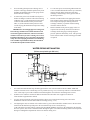
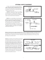
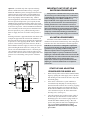
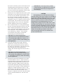
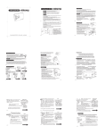
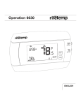
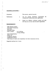
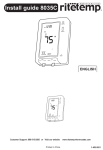
Bulletin No. AY-780-L FLO-RITE-TEMP INSTANTANEOUS WATER HEATER INSTALLATION AND ADJUSTMENT INSTRUCTIONS FOR SINGLE AND DOUBLE WALL UNITS This bulletin should be used by experienced personnel as a guide to the installation of the FLO-RITE-TEMP Instantaneous Water heater. Selection or installation of equipment should always be accompanied by competent technical assistance. You are encouraged to contact Armstrong International, Inc. or its local sales representative for additional information. FLO-RITE-TEMP INSTANTANEOUS WATER HEATER INSTALLATION AND ADJUSTMENT INSTRUCTIONS NOTICE No water heater will work satisfactorily if improperly installed and operated. These instructions contain important information for the installation and adjustment of the FLO-RITE-TEMP Water Heaters. Read these instructions carefully before installing this unit. FAILURE TO ADHERE TO THESE INSTRUCTIONS COULD RESULT IN SERIOUS BODILY INJURY OR PROPERTY DAMAGE. STEAM PIPING INSTALLATION OF A SINGLE UNIT Single and Double Wall Steam In Safety Relief Valve Gate Valve Armstrong Pressure Reducing Valve (if req'd) GP-2000 Armstrong TVS Trap Pressure Gauge Armstrong Thermostatic Air Vent 2-15 psig Steam in the Shell Vacuum Breaker Armstrong I.B. Trap NOTE: FLO-RITE TEMP is provided with (1) one Armstrong Steam Trap and Thermostatic Air Vent (shaded). All other items shown not included. Fig. 2-1 NOTE: units may be piped in parallel for larger capacity requirements. See Fig. 15-1 for an example of parallel unit installation. The unit includes the mixing valve mounted to the heat exchanger, channel iron and U-bolts mounted, thermostatic air vent installed on the heat exchanger, a water pressure pop off valve integral to the unit control valve and a separate Armstrong Inverted Bucket Steam Trap. STEAM SIDE INSTALLATION 1. (Refer to Fig. 2-1) Install the FLO-RITE-TEMP with adequate room to allow for tube bundle removal when cleaning is required. See Table 12-1 for specific dimensions. 2. If 2-15 psig of steam is available a pressure reducing valve is NOT required. If a pressure reducing valve is required, an Armstrong Inverted Bucket Steam Trap is recommended to drain condensate at the inlet of the pressure reducing valve. 3. An Armstrong Y-strainer should be installed before the pressure reducing valve to reduce the chance of dirt fouling. 2 4. If an externally piloted pressure reducing valve is used, the control pipe should be pitched away from the PRV and installed at the pressure gauge on the shell of the heat exchanger. 5. A steam safety relief valve should be used prior to the heat exchanger if either or both of the following conditions exist. (1) If the maximum steam pressure could exceed the minimum water pressure in the tubes, or (2) The maximum steam pressure could exceed 150 psig (the maximum steam pressure rating of the shell). 6. To vent start-up air, an Armstrong Thermostatic Air Vent is included and installed on the top connection, opposite the trap drain connection of the heat exchanger. This discharge can be piped to drain or the floor if preferred. 7. Install a vacuum breaker in the piping between the heat exchanger drain connection and the steam trap. This will prevent improper draining of the heat exchanger caused by a possible vacuum forming when the steam is shut off. 8. Install a suitable steam pressure gauge in the 1/4" coupler located in the top mid section of the heat exchanger shell. This gauge will help diagnose pressure problems should they occur. This port may also be used for a PRV external control pipe if a PRV is required. IMPORTANT -Steam supply pipe size coming to the heat exchanger should NOT be smaller than the steam connection supplied on the heater, otherwise steam flow could be restricted. If a pressure reducing valve is used, installation should be as close as possible to the Flo-RiteTemp. Downstream piping from the Pressure Reducing Valve should be expanded immediately after the PRV to accomodate the expanded volume of steam. WATER PIPING INSTALLATION (Follow same plumbing for DW units) D A C F B C E A B Fig. 3-1 1. An 18 inch minimum thermal loop should be piped into the water inlet and outlet of the FLO-RITE-TEMP and should be located as close to the mixing valve as possible (See Fig. 3-1A). These loops will act as a thermal check valve or heat trap to prevent the conduction of heat through the water from the unit during inactive times. 2. Isolation valves and hose connections added to both the inlet and outlet water supplies will allow for Clean-In-Place equipment to be utilized. 3. Use pipe unions on both the water inlet and outlet to allow ease of water heater mixing valve removal for maintenance and removal of the tube bundle for cleaning (See Fig. 3-1A). 4. For adjusting the unit, an isolation valve and hot water by-pass to drain should be installed close to the unit down stream from the thermal loops and prior to the recirculation loop (if one is used) (See Fig. 3-1B). This allows for quick and easy setting of the FLO-RITE-TEMP by one person. By isolating the unit from the hot water system, flow can be controlled to drain through the globe valve while monitoring outlet water temperature during low and high flow adjustments on the water heaters mixing valve. 3 Minimum line sizes to drain should be as follows: model 415 = 3/4", model 535 = 1", model 665 = 1-1/4", model 8120 = 2". Line sizes smaller than these will not allow sufficient flow for making high flow settings on the mixing valve. 5. 6. 7. A water temperature gauge should be installed directly after the by-pass drain valve. This thermometer is only used for inital temperature adjustments of the Flo-Rite-Temp or troubleshooting the unit. (See Fig. 3-1B) If a recirculation system is used with a FLO-RITETEMP, a small diverting valve must be piped into the loop return downstream of the recirculating pump (See Fig. 3-1C). This device is used to divert recirculated water back to the heater for reheating if the temperature of the water drops too low due to no hot water demand from the system plus piping radiation losses (See page 9 for operation explanation). Be sure to pipe in unions and isolation valves to facilitate diverting valve removal required when element replacement is needed. A throttling type valve should be installed in a full return line size bypass around the diverting valve in order to balance the flow to the diverting valve. This is especially needed when recirculating pumps are large or oversized. For a recirculated system, a small constant running pump should be piped in on the return side of the loop (See Fig.3-1D). This pump should be sized to move approximately 10% of the maximum rated gpm of the FLO-RITE-TEMP in the system with enough head to overcome the head encountered in the loop. NOTE: A thermometer should be installed in the outgoing loop to monitor system temperature (Fig. 3-1E). A thermometer may also be installed on the loop return to monitor temperature drop through the loop or to help troubleshoot the diverting valve (Fig. 3-1D). The thermometer referred to in point #4 and Fig. 3-1B should only be used to set the FLO-RITE-TEMP and never used to monitor system temperature. NOTE: Expansion tanks should be used in on/off demand applications where there is a short duration of time from high flow to no flow of water, i.e., a shut off time of 10 seconds or less. (See Fig. 3-1F) Pop-Off Valve Installation Instructions 1. Thread relief valve into the 1/4" NPT port located on the lower diaphragm half near the spring chamber. See drawing 4-1. 2. Tighten with a 3/4" wrench. Warning: Do Not Over Tighten. Distortion can result causing the relief valve not to seat. Note: The discharge of the relief valve is 1/4" FPT and can be piped over to a drain to prevent the relief valve discharge from going onto the floor underneath the Flo-Rite-Temp. supplied with each heater. The valve is a self relieving and self seating valve which will open due to thermal expansion or hydrolic shock. Continuous or intermittent discharge of this valve while heater is in service could indicate a system pressure problem. See note for (Figure 3-1F) expansion tanks on previous page possible solutions. Drawing 4-1. Note: The function of this pressure relief valve is to relieve any excess pressure on the water side of the Flo-Rite-Temp resulting from system water hammer or water expansion pressure due to water heating. If the problem is severe, water hammer arrestors should be placed on all equipment with fast closing water valves. Expansion tanks should be used for all expansion pressure problems. The relief set point of this valve is 165 psig. Note: The Armstrong Flo-Rite-Temp comes supplied with a 1/4" NPT water pressure relief valve. The standard valve has a cracking pressure of 165 psig. Installation instructions (AY-700) are Note: For hard water applications, pipe pop-off valve into a dirt leg. 4 OPTIONAL SAFETY EQUIPMENT See Fig. 3-1E for location of each option within the system. All options would be installed downstream of the water heater in the outgoing recirculation loop, if one is present, or downstream of the hot water thermal loop if recirculation is not used but always before the first hot water take off from the system. Temperature Relief Valve Loop or System Thermometer Option #1 A temperature relief valve set at roughly 15-30 degrees above that of the FLO-RITE-TEMP will help prevent any chance of overheated water reaching the faucets. (NOTE: Normally unit will fail closed and either no water or only cold water will flow from the unit.) Hot Water from Flo-Rite-Temp Option #1 Option #2 A 3-way blending valve with a set point 1030 degrees above that of the FLO-RITE-TEMP will help prevent the chance of overheated water reaching the faucets in the event of unit failure. Under normal operating conditions the hot water flows straight through the blending valve from Port B to Port A. But in the event of an overheated situation, the blending valve will open Port C to add sufficient cold water to maintain a constant temperature . (NOTE: The blending valve should be sized to handle the maximum flow of the system). Loop or System Thermometer 3-Way Thermostatic Valve Hot Water from Flo-Rite-Temp To Flo-Rite-Temp Cold Water Supply Option #2 Note: The Armstrong Flo-Rite-Temp comes supplied with a 1/4" NPT water pressure relief valve. The standard valve has a cracking pressure of 165 psig. Installation instructions (See AY-700) are supplied with each heater. The valve is a self relieving and slef seating valve which will open due to thermal expansion or hydrolic shock continous or intermiten discharge of this valve while heater is in service could indicate a system pressure problem. See note for (fig. 31F) on previous page for possible solution. Option 3A Loop or System Thermometer Temperature To steam Switch shut-off valve Hot Water Supply From Flo-Rite-Temp Option 3B To Steam Shut-Off Valve ! Option #3 A temperature switch installed well downstream of the Flo-Rite-Temp outlet on a non-recirculated system or just into the outgoing recirculated system loop on a recirculated system, with a set point 15-30 degrees above that of the FLO-RITE-TEMP will help prevent the chance of overheated water reaching the faucets in the event of system problems. This switch can be used to turn off the steam supply to the heater in the event of overheating. The most economical way to accomplish this is with a solenoid on the PRV. A full ported motorized valve on the steam supply line may also be used. Option 3B. Along these same lines, a pressure switch installed in the inlet water line would shut down the supply steam on the heat exchanger in the event of water pressure loss, preventing thermal shock and water hammer to the unit. Pressure Switch Option #3 5 Cold Water Supply to Flo-Rite-Temp IMPORTANT UNIT START-UP AND SHUTDOWN PROCEDURES Option #4 (Available only when a pressure reducing station is installed on the Flo-Rite-Temp). Using the Model GP-2000W1P system, when piped as shown in the Option 4 drawing, will provide a safe dependable shut down of the main steam valve when the water pressure fails or drops rapidly on the Flo-Rite-Temp. Unlike a solenoid application, which shuts the steam down when the water pressure drops below a pre-set point, the GP2000W1P offers another benefit that it allows the system to keep producing hot water even when the water pressure is below the set pressure. The GP-2000W1P Combination valve essentially lets the steam pressure modulate below the water pressure by 2 or 3 pounds, allowing a water heater to supply hot water even when water pressure is low. Its important to remember that water pressure must ALWAYS be greater than steam pressure on the unit to avoid boiling the water in the tubes of the heat exchanger. When starting up a FLO-RITE-TEMP it is very important that the water supply is turned on to the unit before any steam is turned on. Once the unit is up and running, the inlet water valve should never be closed unless the steam is turned off first. When shutting down a unit you should always first shut off the steam and then allow water to run through the unit until it has cooled and completely condensed all remaining steam in the heat exchanger before closing off the supply water to the unit. Incoming cold water is piped into the hot water heater with a sample line piped to the W-1 Pilot of GP-2000W1P. At the same time the cold water is supplying the water heater, its pressure it is also supplying the W-1 Pilot. When the pressure of the incoming cold water decreases, the W-1 Pilot modulates down the supply of steam to the pressure pilot controlling the main steam valve, acting as a nonelectric self-controlled shutdown device. Ultimately, this valve eliminates the use of any electricity and gives the customer safe control of their hot water supply when water pressure loss or fluctuating water pressure conditions exist. Steam ADJUSTING PROCEDURES All models of FLO-RITE-TEMP’s have two settings which need to be made on initial start-up. One setting must be made at low flow while the other is made at high flows. IMPORTANT: Once the low and high flow adjustments have been made, the unit generally need not be adjusted again unless your operating conditions change or a different set point is desired. A significant drop in temperature output or capacity is an indication of a bad diaphragm or that the tube bundle needs to be cleaned. Do not readjust the valve unless isolation of the unit from the system and running water to drain produces poor temperature control. If capacity is minimal, check the diaphragm or clean the bundle but do not readjust the control valve. START-UP AND ADJUSTING PROCEDURE FOR MODEL 415 1. Before turning on the steam to the FLO-RITE-TEMP, begin by opening the water supply valve to the unit and checking for water leaks at the unit or any of the associated piping. 2. If the unit is connected to a system which has a recirculation loop and pump, be sure the pump is turned off and the isolation valve on the leg of piping going from the diverting valve back to the inlet of the FLO-RITE-TEMP is closed (this is the isolation valve downstream of port “B” of the thermostatic diverting valve). (See Fig. 3-1) 3. Close the isolation valve on the hot water outlet of the unit and open full and close several times the throttling bypass valve to drain to purge all the air from the FLO-RITE-TEMP. (See Fig. 3-1B). This process also primes the units lower diaphragm area with water. Failure to do this prior to initial adjustment can result in inaccurate settings and poor results. Condensate Hot Water Outlet Cold Water Inlet Option #4 6 4. Throttle the bypass valve to drain so that a constant 3 gpm of flow may pass to drain. 5. Slowly open steam valve or adjust the pressure reducing valve to allow 2 - 15 psig of steam pressure on the unit (CAUTION: always make sure there is water pressure on the unit before adding steam. Failure to do this will cause severe hammering of the unit and possible damage). 6. 7. 10. To make the high flow adjustment, SLOWLY increase the flow of water through the unit to drain while monitoring the outlet thermometer. When the outlet temperature has dropped by approximately 10 °F below set point for a Model 415E, make your high flow adjustment while maintaining that flow. 11. Place a small screw driver or center punch through the hole in the high flow adjustment stem (see Fig. 7-1) and turn it in a clockwise direction. This will start to close the valve restricting the cooling water and cause the outlet water temperature of the unit to rise. Continue until the outlet temperature is back up to your required set point. Make sure that the steam trap draining the unit is functioning properly and allow the entire unit to come up to temperature for at least three to five minutes while passing the 3 gpm of water flow to drain before beginning the adjustment of the unit. (IMPORTANT - When making the high flow adjustment the low flow adjustment SHOULD NOT rotate with the high flow adjustment. If it does, you will have to hold it stationary while making your high flow adjustment). Locate the low and high flow adjustments on top of the mixing valve hidden under the hex bonnet (see Fig. 7-1). Before beginning adjustments, check to make sure the high flow adjustment is fully open. To do this start by pressing down on the high flow adjustment when water pressure is present on the unit and there is no water flow through the unit. This should only depress about 1/8". If it pushes in further, turn the adjustment stem counter clockwise to open. Check every turn until there is only 1/8" travel to the high flow stem when pushed down (Note: with water pressure on the unit the stem should pop back up after depressing it). If the high flow adjustment stem will not depress at all the valve is opened too far and you must turn the adjustment clockwise until there is 1/8" travel downward to the stem. 8. With the unit now isolated from the hot water system and all flow of water being directed to drain at 3 gpm, let the temperature stabilize. 9. Monitor the outlet temperature on the gauge located in the bypass to drain (see Fig. 3-1B). Place an adjustable wrench on the flats of the low flow adjustment (see Fig. 7-1). 12. The unit is now adjusted. (IMPORTANT - If for any reason you must readjust the unit, you will first have to return the high flow adjustment back to its full up position as stated in point # 7). START-UP AND ADJUSTING PROCEDURE FOR MODEL 535EP, 665SEP and 8120 Figure 7-1 High Flow Adjustment (HFT) Low Flow Adjustment (LFT) Top Of Mixing Valve Follow all the steps 1-6 as stated in the adjustment procedures of the model 415. Turning clockwise raises the discharge temperature and counter-clockwise lowers the discharge temperature. Make the appropriate adjustment to achieve the desired set point. For example if a set point of 140 °F is desired and the temperature reading is 155 °F, you must turn the low flow adjustment counter-clockwise to lower the set point temperature from 155 °F down to 140 °F. 7. (IMPORTANT - When making the low flow adjustment the high flow adjustment shaft SHOULD rotate with the low flow adjustment. If it does not do so, you will have to turn it by hand while making the low flow adjustment). Allow the unit to stabilize to be sure that the unit will remain at the desired set point. The low flow is now adjusted and should not be readjusted. 7 Locate the low flow temperature adjustment (LFT) and the high flow temperature adjustment (HFT) on top of the mixing valve hidden under the hex bonnet (See Fig. 7-1). Before beginning adjustments, check to make sure the LFT is fully closed. To do this, turn the LFT clockwise until it stops. Also make sure the HFT is fully open. To do this start by pressing down on the HFT when water pressure is present on the unit and there is no water flow through the unit. The HFT should only depress about 1/8". If it pushes in further, turn the HFT stem counter clockwise to open. Check every turn until there is only 1/8" travel to the HFT when pushed down (Note: with water pressure on the unit the stem should pop back up after depressing it). If the HFT stem will not depress at all the valve is opened too far and you must turn the adjustment clockwise until there is 1/8" travel downward to the stem. 8. 9. With the unit now isolated from the hot water system and all flow of water being directed to drain, slowly increase the water demand to approximately 3/4 of the maximum capacity according to the capacity chart on page 13. When starting a cold system, you should take at least 2 to 3 minutes to slowly increase to this demand. This will allow time for the steam piping feeding the unit to come up to temperature, pressure and purge itself of excess condensate. Place a small screwdriver or center punch through the hole in the HFT adjustment and slowly turn the HFT to change the temperature to the desired set point. Close (clockwise) the HFT to raise the outlet water temperature. Allow adequate time for the water temperature to stabilize. This could take several minutes if the piping is cold and the measurement point is far from the unit. (IMPORTANT: When making the HFT adjustment, the LFT adjustment SHOULD NOT rotate with the HFT adjustment. If it does, you will have to hold it stationary while making your HFT adjustment). 10. Lower the water flow rate to 3 gpm. The LFT adjustment is currently fully closed (see step 8). Slowly open (counterclockwise) the LFT to lower the outlet water temperature to the desired set point. Allow adequate time for the temperature to stabilize.This will take longer since the flow rate is so small. (IMPORTANT: When making the LFT adjustment, the HFT adjustment shaft SHOULD rotate with the LFT adjustment. If it does not do so, you will have to turn it by hand while making the LFT adjustment). 11. Recheck the outlet water temperature at 3/4 of the maximum demand it will see. Adjust if necessary. Opening the HFT (counterclockwise) will lower the temperature and closing the HFT (clockwise) will raise the temperature. Note: You may want to fine tune the HFT adjustments during normal operation of the unit at heavy demand. If outlet temperature is slightly low, turn HFT clockwise to raise it. This should only be done during the initial service of the unit or when the unit has been cleaned. Never attempt to re-adjust the unit with a dirty tube bundle - always clean tube bundle first. The unit is now adjusted. 8 (IMPORTANT: If, for any reason, you must readjust the unit, you will first have to return the LFT adjustment to the fully closed position as stated in step 8). CAUTION When putting a heavy load on the heat exchanger, watch the steam pressure gauge. This pressure should not be permitted to fall below 2 psig. If it does and severe water hammer develops, reduce the load by closing some of the faucets or shut the system down. When steam pressure drops under heavy load and hammering occurs, not enough steam is getting to the unit. This can be a result of an undersized reducing valve, lack of boiler capacity or restrictive steam lines. Hammering can also be caused by a loss of water pressure where the water pressure in the unit falls below the pressure of steam. This condition is usually caused by improper shutdown of the unit or someone closing the inlet water valve with the steam pressure still on the unit. FLO-RITE-TEMP Recirculation System Piping and Operation Because of its relatively small size and compactness, the FLO-RITE-TEMP can easily be installed close to the point of water use eliminating the need for a recirculation system. Three-way Thermostatic Capsule - This device has a set point roughly 20 degrees below the set point of the FLO-RITE-TEMP and will maintain the temperature in the loop between the set point of the capsule and the set point of the FLO-RITETEMP. The capsule senses the temperature of the recirculated water and compares it with its pre-set temperature. If the temperature in the loop drops below the capsule's set point because of radiation loss from the piping and no hot water demand from the loop, then the capsule begins to divert some of the loop's flow to the inlet of the FLO-RITE-TEMP (ports A to B) for reheating. This diversion will bring the temperature of the loop back up to its required temperature. Once the temperature in the loop is over the capsule’s set point all flow from the recirculation pump now goes straight through the capsule (ports A to C) and the return water is fed back to the hot water supply line. To regulate flow to the capsule, a balancing/bypass line with globe valve is required. In applications where water heaters are located in basements or utility rooms and feed an entire building or wing a recirculation system or loop must be utilized to assure instantaneous hot water to all usage points. The recirculation system is made up of several different components designed to work together to maintain the temperature of the water in the loop at times of low or no flow. Recirculation pump - This is a constant GPM pump that runs continuously regardless of the hot water demand from the loop. Its function is to continually recirculate the water in the loop in order to maintain the temperature during low or no flow conditions. As a rule of thumb, the capacity of the pump should be approximately 10 to 15 percent of the maximum capacity of the FLO-RITE-TEMP and be able to overcome any head found in the loop. The recirculation pump however, may be larger than 15 percent. But when a larger pump is used, a full line size bypass with a globe valve must be piped to divert most of the flow around the thermostatic capsule. This diverting recirculating system eliminates the need for aquastats and any electrical wiring. It is a self contained, self regulating system that controls the temperature of the water in the loop during low or no hot water demand situations. When there is a demand for hot water the temperature of the water introduced into the system is instantly controlled by the FLO-RITE-TEMP feed forward mode of operation. Recirculation Pump Capsule Balance Line Globe Valve 3-Way Thermostatic Capsule A C B Loop or System Thermometer Bypass to drain Unit Setting Thermometer Fig. 9-1 9 FLO-RITE-TEMP-Accumulation System For peak load conditions or to avoid large intermittent steam demands The FLO-RITE-TEMP water heater accumulation system is designed to provide a specified volume of accumulated hot water for short duration peak loads or when steam is in short supply and a recovery time can be tolerated. During periods of low or no demand, the water in the accumulator tank is heated to the set point temperature by the FLO-RITE-TEMP water heater. An accumulator or large storage tank is installed in series with the FLO-RITE-TEMP water heater. Cold water is piped to the inlet of the water heater and into the bottom of the accumulator tank. Hot water flows from the FLO-RITE-TEMP directly to the accumulator tank through a pump that is controlled by an aquastat. When the pump is off the flow goes to the accumulator via a bypass around the pump. This would occur when there is hot water demand and the temperature in the tank is at set point. In operation, hot water is drawn off the top of the tank at the same time as cold water enters from the bottom and hot water from the FLO-RITE-TEMP enters the tank from the side. When the peak load stops and the aquastat senses the cooler water in the tank, the pump starts and the heating process begins another cycle. A bypass line from the heater to the hot water demand is shown and is normally kept closed. When the accumulator tank requires maintenance this bypass allows the tank to be isolated, with hot water beingsupplied by the FLO-RITE-TEMP only. When the system is started the water in the accumulator tank is cold which causes the aquastat to turn the pump on. Water flows out of the bottom of the tank to the inlet of the FLO-RITE-TEMP. The water continues this cycle until the aquastat in the tank senses the appropriate temperature. At that time the pump shuts off and the water is ready for use. The globe valve on the bottom of the accumulator tank should be adjusted at full system demand so that a pressure differential of approximately 8 psi is read across the FLO-RITE-TEMP. Fig. 10-1 10 Advantages of the accumulation system are: ! Accumulation tank temperatures are restored over a period of time avoiding large intermittent steam demands. ! Providing the FLO-RITE-TEMP's safety features to the entire system. ! Providing accurate hot water temperature control. ! Providing a back up alternative during tank maintenance. ! To allow accumulator tanks to be relatively small in size because hot water demand is supplemented by the FLO-RITE-TEMP. Flo-Rite-Temp Tempered Water Systems For Safety Shower/Eye Wash Stations The problem which faces many companies today is how to safely warm water to be used effectively in a drench shower or safety shower situation. adjusted set point within this temperature range, usually the lowest set point of 120O degrees is used). The 120°F water can be piped to the Rada Z358 thermostatic mixing valve which will blend cold water with the 120°F water to make the tepid water for the safety shower/eye wash station. The Rada Z358 valve is equipped to allow cold water to the showerhead in the event of hot water failure. Storage tank units can run out of warm water causing people to go into possible shock due to cold water exposure or to end the shower before proper flushing has taken place. Also, because the water in the tank is only heated to a temperature range of 65 to 95 degrees F. there is the potential and risk of legionella bacteria forming inside of the tank. Lastly, tank systems are feedback systems which can cause severe overheating of the water when thermostatic elements fail causing personal injury. The Rada Z358 Mixing Valve (see Bulletin ALIB-Z358-20) properly proportions the hot and cold incoming water to obtain a preset delivery temperature to the drench shower head. Demand induced changes are sensed and automatically compensated for by the valve so that shower output temperature remains constant. A recirculation system may also be incorporated in this system and is especially recommended in applications where shower lines are exposed to the cold air or shower heads are a distance from the heater. The solution is to use the Armstrong Flo-RiteTemp tankless instantaneous feedforward water heater in series with a self-contained fail safe thermostatic mixing valve. How The System Works Feedforward control in the water heater eliminates the danger of thermostatic element failure and overheating typical in storage tank feedback systems. Because there is no storage tank, there is no danger of legionella forming in the stored warm water. All water is heated instantaneously on the spot, there is no shortage of heated water or shower time limits. The system, when piped as shown in the drawing, will provide a safe, continuous and dependable source of accurately controlled warm water. Incoming cold water is heated between 120 to 130 degrees F by the Flo-Rite-Temp. (The unit is set to provide a constant supply of hot water at an Option 1: Water recirculation when heater is servicing a long run to the shower head, more than one shower head, or piping is exposed to cold ambient temperatures Fig. 11-1 11 Single Wall and Double Wall Profile Model 415 and 535 Profile Shown (665 and 8120 valve shows that connections for water inlet and outlet are on opposite sides of the valve body). Fig. 12-1 Table12-1. 12-1. Dimensions Dimensionsand & Weights Table Weights Dimensions Model 415 535 665 8120 415DW 535DW 665DW 8120DW in mm in mm in mm in mm in mm in mm in mm in mm A 54 1372 67-1/2 1715 82 2083 85 2159 76-1/8 1934 77-3/8 1965 90-5/8 2302 79-7/8 2029 B 4-1/2 114 5-1/4 133 5-3/4 146 5-3/4 146 4-1/2 114 5-1/4 133 5-3/4 146 5-3/4 146 C 7-1/2 190 8-5/8 219 10-3/8 264 11-3/4 299 7-1/2 190 8-5/8 219 10-3/8 264 11-3/4 298 D 7 178 9 229 10-3/8 264 12 305 7 178 9 229 10-3/8 264 12 305 E 4-1/2 114 5-9/16 141 6-5/8 168 8-5/8 219 4-1/2 114 5-9/16 141 6-5/8 168 8-5/8 219 F 3-1/2 89 4 102 4-3/4 121 6-1/8 156 3-3/8 86 4 102 4-3/4 121 6 152 G 3-1/2 89 4-1/2 114 5-1/2 140 8-7/8 225 3-3/4 95 4-1/4 108 5 127 8-3/4 222 Connections H J K L 7 5 6-1/4 50 178 127 159 1270 7-7/8 6 7-1/2 62 200 152 191 1575 9-1/4 7-1/2 8-3/4 74 235 190 222 1880 9-1/2 8 9-1/2 74 241 203 241 1880 10-1/2 5 6-7/8 75 267 127 175 1905 11-1/2 6 8-1/8 75 292 152 206 1905 11-3/4 7-1/2 9-3/4 87 298 191 248 2210 12-5/8 8 11-5/8 75 321 203 295 1905 M 7-1/2 190 9 229 11 280 12-3/8 314 7-1/2 190 9 229 11 280 12-3/8 314 1 1" NPT 25 1-1/2" NPT 40 2" NPT 50 3" NPT 80 1" NPT 25 1-1/2" NPT 40 2" NPT 50 3" NPT 80 2 3/4" NPT 20 1" NPT 25 1-1/4" NPT 32 2" NPT 50 3/4" NPT 20 1" NPT 25 1-1/4" NPT 32 2" NPT 50 3 2" NPT 50 2-1/2" NPT 65 3" NPT 80 4" 150# ANSI 100 2" NPT 50 2-1/2" NPT 65 3" NPT 80 4" 150# ANSI 100 Wt. lb kg lb kg lb kg lb kg lb kg lb kg lb kg lb kg 133 60 235 107 358 162 585 265 199 90 270 122 444 201 665 302 Double Wall Single Wall Table 12-2 Materials Body Valve Valve Seats (415) 303 Stainless Steel with Teflon Inserts (535/665/8120) Brass (415/535) 303 Stainless Steel (665/8120) Brass (415DW) 303 SS with Teflon Inserts (415DW/535DW) 303 SS 535DW/665DW/8120DW Brass (665DW/8120DW) Brass Bronze Diaphragm Viton® GF Reinforced with Nomex® Fiber Heat Heat Exchanger Exchanger Tubes Shell Carbon Steel ASME "U" Stamped Tube Sheets** Tube Bundle End Cap 5/8" 16 BWG Admirality Brass Brass Brass 5/8" Copper Inner Tube 3/4" I.D. Grooved Copper Outer Tube Steam Side Steel/Water Side Brass N/A Note: ** There is an open vent to atmosphere between the tube sheets to detect tube failure. Table 12-3. Specifications Application Steam to Water Steam Supply Pressure 2 - 15 psig (0.14 - 1.0 bar) Water Supply Pressure 20 - 125 psig (1.4 - 8.5 bar) 12 Maximum Water Pressure Drop 10 psig (0.7 bar) FLO-RITE-TEMP Table 13-1 CAPACITIES AND STEAM LOADS Standard Hot Water Capacities* Steam Capacities Inlet Set Steam Pressure Steam Pressure Temp. Temp. psig psig psig psig psig psig psig psig °F °F 2 5 10 15 2 5 10 15 lb/hr lb/hr lb/hr lb/hr lb/hr lb/hr lb/hr lb/hr 17 18 20 20 714 767 839 901 37 40 43 45 1543 1657 1814 1946 120 69 74 80 80 2855 3067 3356 3601 142 145 145 145 5680 6160 6760 7160 15 16 17 18 681 734 807 868 32 34 37 39 1472 1587 1743 1876 130 58 63 68 73 2723 2936 3226 3472 112 122 136 145 5040 5490 6120 6705 12 13 15 16 646 700 773 835 27 29 32 34 1397 1513 1671 1804 40 140 50 54 59 63 2585 2799 3091 3338 88 97 109 120 4400 4850 5450 6000 9 10 11 12 572 627 702 765 20 22 24 26 1235 1355 1517 1652 160 37 40 45 48 2286 2508 2806 3057 69 83 89 95 4140 4980 5340 5700 5 5 6 7 344 386 441 487 12 13 15 16 861 966 1104 1219 180 23 26 29 32 1663 1866 2134 2355 43 47 52 59 3010 3290 3640 4130 19 20 20 20 692 745 816 877 41 44 45 45 1495 1609 1764 1896 120 76 80 80 80 2767 2977 3264 3508 145 145 145 145 5740 6090 6580 7035 16 17 19 20 660 712 785 846 34 37 40 43 1425 1539 1695 1827 130 64 68 75 80 2637 2848 3137 3381 127 138 145 145 5080 5520 6120 6760 13 14 16 17 626 679 752 813 29 31 34 37 1352 1467 1624 1756 50 140 54 58 64 68 2502 2715 3005 3250 99 108 121 134 4455 4860 5445 6030 10 11 12 13 553 608 682 744 21 23 25 28 1194 1313 1473 1607 160 39 42 47 51 2210 2429 2725 2974 76 90 95 102 4180 4950 5225 5610 7 6 6 7 332 373 428 473 12 14 16 17 831 934 1071 1185 180 24 27 30 33 1605 1805 2069 2289 49 55 63 72 3185 3575 4095 4680 18 19 20 20 638 690 762 822 38 41 45 45 1378 1491 1646 1777 130 70 76 80 80 2550 2760 3046 3288 145 145 145 145 5110 5565 6090 6510 15 16 17 19 605 658 729 790 32 34 38 40 1307 1421 1576 1708 140 58 63 69 75 2418 2629 2917 3160 111 123 137 145 4440 4920 5480 6080 60 10 11 13 14 533 588 661 723 22 24 27 30 1152 1270 1428 1561 160 41 45 50 55 2132 2349 2642 2889 85 99 104 115 4250 4950 5200 5750 5 6 7 7 320 360 414 459 13 14 16 18 800 902 1037 1150 180 25 28 32 35 1546 1743 2004 2221 59 67 80 90 3540 4020 4800 5400 Inlet Temp. °C Set Temp. °C 49 54 4 60 71 82 49 54 10 60 71 82 54 60 16 71 82 Standard Hot Water Capacities* Steam Capacities Steam Pressure Steam Pressure bar bar bar bar bar bar bar 0.14 0.35 0.7 1 0.14 0.35 0.7 kg/hr kg/hr m3/h m3/h m3/h kg/hr m3/h 3.8 4.1 4.5 4.5 323 347 379 8.4 9.1 9.8 10.2 697 749 820 15.7 16.8 18.2 18.2 1290 1386 1517 32.2 32.9 32.9 32.9 2576 2794 3066 3.4 3.6 3.8 4.1 308 332 365 7.3 7.7 8.4 8.8 665 717 788 13.2 14.3 15.4 16.6 1230 1327 1458 25.4 27.7 30.9 32.9 2286 2490 2776 2.7 3.0 3.4 3.6 292 316 349 6.1 6.6 7.3 7.7 631 684 755 11.3 12.2 13.3 14.3 1168 1265 1397 20.0 22.0 24.7 27.2 1996 2200 2472 2.0 2.3 2.5 2.7 259 283 317 4.5 5.0 5.5 5.9 558 612 686 8.4 9.1 10.2 10.9 1033 1134 1268 15.6 18.8 20.0 21.6 1878 2259 2422 1.1 1.1 1.4 1.6 156 175 200 2.7 3.0 3.4 3.6 390 438 501 5.2 5.9 6.6 7.3 754 846 968 9.7 10.7 11.8 13.4 1365 1492 1651 4.3 4.5 4.5 4.5 313 337 369 9.3 10.0 10.2 10.2 676 727 797 17.3 18.2 18.2 18.2 1251 1346 1475 32.2 32.2 32.2 32.2 2603 2762 2985 3.6 3.8 4.3 4.5 298 322 355 7.7 8.4 9.1 9.8 644 696 766 14.5 15.4 17.0 18.2 1192 1287 1418 28.8 31.3 32.2 32.2 2304 2504 2776 2.9 3.2 3.6 3.8 283 307 340 6.6 7.0 7.7 8.4 611 663 734 12.2 13.2 14.5 15.4 1131 1227 1358 22.5 24.5 27.5 30.4 2021 2204 2470 2.3 2.5 2.7 3.0 250 275 308 4.7 5.2 5.7 6.4 540 593 665 8.9 9.5 10.7 11.6 999 1098 1232 17.2 20.4 21.6 23.1 1896 2245 2370 1.1 1.4 1.4 1.6 151 169 194 2.7 3.2 3.6 3.9 377 424 486 5.4 6.1 6.8 7.5 728 819 938 11.1 12.5 14.3 16.3 1445 1622 1857 4.1 4.3 4.5 4.5 288 312 344 8.7 9.3 10.2 10.2 623 674 744 15.9 17.3 18.2 18.2 1152 1247 1377 32.2 32.2 32.2 32.2 2318 2524 2762 3.4 3.6 3.8 4.3 273 297 330 7.3 7.7 8.6 9.1 591 642 712 13.2 14.3 15.7 17.0 1093 1188 1318 25.2 27.9 31.1 32.2 2014 2232 2486 2.3 2.5 2.9 3.2 241 266 299 5.0 5.5 6.1 6.8 521 574 645 9.3 10.2 11.3 12.5 964 1062 1194 19.3 22.5 23.6 26.1 1928 2245 2359 1.1 1.4 1.6 1.6 145 163 188 3.0 3.2 3.6 4.1 363 409 470 5.7 6.4 7.3 7.9 701 791 909 13.4 15.2 18.1 20.4 1606 1823 2177 bar 1 kg/hr 407 880 1628 3248 392 848 1569 3041 377 815 1509 2722 346 747 1382 2585 221 553 1068 1873 396 857 1586 3191 382 826 1528 3066 367 794 1474 2735 336 726 1344 2545 214 537 1037 2123 372 803 1486 2953 357 772 1428 2758 327 703 1306 2608 208 522 1007 2449 Model 415 535 665 8120 415 535 665 8120 415 535 665 8120 415 535 665 8120 415 535 665 8120 415 535 665 8120 415 535 665 8120 415 535 665 8120 415 535 665 8120 415 535 665 8120 415 535 665 8120 415 535 665 8120 415 535 665 8120 415 535 665 8120 *Units may be piped in parallel when desired capacities exceed that of a single unit. Notes: Minimum water temperature increase is 60°F (33°C). Consult factory if less than 60°F (33°C) increase in required or a set temperature of below 120°F (49°C) is required. See Armstrongs All Products Catalog 326 for proper pressure reducing valve selection. 13 TROUBLESHOOTING GUIDE Table 14-1 Problem Causes Solutions The steam is not turned on to the unit. The water tubes in the heat exchanger are Only cold water plugged. comes out of The differential pressure sensing diaphragm the unit. is ruptured. The mixing valve is not properly adjusted. The steam pressure is too low. Air has accumulated in the shell of the heat exchanger. Only warm The flow is above the rated capacity of the water comes unit. out of the unit. The tubes in the heat exchanger are scaled. Extreme hot water comes out of the unit. No water comes out of the unit. The unit hammers and bangs during operation. The mixing valve is not properly adjusted. The steam pressure is too high. Recirculated water is continually diverting through the Flo-Rite-Temp. The steam is superheated. The mixing valve is not properly adjusted. Open steam valve to the unit. See Clean-In-Place operating instructions or remove tube bundle and clean. Replace the diaphragm. Adjust the unit according to the instructions. Increase steam pressure (2 - 15 psig). Install a thermostatic air vent on the shell. Make sure unit is sized properly. See Clean-In-Place operating instructions or remove tube bundle and clean. Adjust the unit according to the instructions. Decrease steam pressure (2 - 15 psig). Check diverting valve for a stuck or failed thermal capsule. Pipe to saturated steam. Adjust the unit according to the instructions. The inlet valve on the water supply is closed. Open valve. There is no demand for hot water. The shell of the heat exchanger is not properly drained. The steam pressure has dropped or a vacuum has formed. The water pressure had dropped below that of the steam pressure and steam is forming inside of the water tubes. Wait till demand is present then re-check. Make sure steam trap is working and properly installed. Make sure shell is level to floor. Do not elevate condensate if pressure is low. Increase pressure and install vacuum breaker at shell drain (Figure 1-1). Install a pressure switch on water inlet to shut off steam on a drop in water pressure. DISASSEMBLY Control Valve - All maintenance on the valve should be done by a factory trained product specialist with the exception of replacing the pressure sensing diaphragm. To replace the diaphragm remove all nuts and bolts from the bottom cover. After removing the bottom cover, remove the lock nuts from the bottom of the valve shaft. You will need to hold the platter to prevent the assembly from spinning, or hold the stem with large a slotted screw driver in the slot at the bottom of the stem. After removing the nuts, slide the platter off, then the old diaphragm, being careful not to lose the brass washer above the diaphragm. To reassemble follow the reverse order. Make sure when tightening the cover bolts that you use a criss-cross pattern. 14 Single Wall Heat Exchanger - To remove the tube bundle for cleaning. Simply unbolt the mixing valve from the shell and move it out of the way. The tube bundle can be pulled out from the valve end (see Table 12-1 for clearance dimensions). Once the tube bundle is out of the shell, unbolt the end cap on the floating head end and remove to provide straight through cleaning. Reassemble in the reverse order (On the Model 665 dual stem unit when reassembling the tube bundle, make sure that the "TOP" indicator stamped on the cover and both ends of the tube bundle line up and bundle is reinstalled in the shell with both "TOP" indicators facing up). New gaskets will be required for this procedure. (Order heat exchanger gasket kit for model number) Armstrong Pressure Reducing Valve (if req'd) Safety Relief Valve Steam In Steam Pressure Gauge System Isolation Valve Armstrong TVS Trap Bypass to Drain for Setting Setting Thermometer 2-15 psig steam in the shell Thermal Loops Armstrong Trap Heated Water I.B. System Isolation Valve Thermostatic Air Vent 2-15 psig steam in the shell Bypass to Drain for Setting Supply Water Setting Thermometer Steam Pressure Gauge Thermal Loops I.B. Vacuum Breaker I.B. Armstrong Trap Armstrong Trap NOTE: Depending on capacity requirements a parallel water heater installation may also require (2) two PRVs in parallel. Single wall installation shown - Double wall would be similar. See your Armstrong Representative for proper reducing valve application. Fig. 15-1 15 Clean-In-Place Operating Instructions When there is a noticeable drop in the Flo-RiteTemp’s — hot water capacity, temperature, or an increased water pressure drop across the unit — tube bundle scale removal should be considered using the commercially available product called RITE-Qwik*. Tube bundle scale removal can be accomplished as follows: Step 1 - Shut off steam supply valve #1 to the Flo-RiteTemp. Step 2 - While the water pressure is still ON and the steam is OFF, run the Flo-Rite-Temp for (10) ten minutes or until the outside of the unit is cool to the touch. Step 3 - Shut the water inlet valve #4 OFF and water outlet valve #5 OFF; open cleaning connection outlet #7. Connect air hose with regulator to valve #9. Turn air on slowly to approximately 5 psi. Increase to maximum of 25 psi. Leave air pressure on until water stops coming out of connection #7. Turn air (valve #9) off. Open cleaning connection inlet #8 and remove the pop-off valve or inlet pipe plug #6 from the lower diaphragm cover of the control valve . Let the remaining water drain by gravity from the Flo-Rite-Temp. Step 4 - After all the water has been drained, reinstall the pop-off valve or pipe plug #6 into the lower diaphragm cover of the control valve. Step 5 - With hose valve closed connect return hose A of the Clean-in-Place to the outlet cleaning connection #7 of the Flo-Rite-Temp. Step 6 - With hose valve closed connect discharge hose B of the Clean-in-Place to the inlet cleaning connection #8 of the Flo-Rite-Temp. Step 7 - Start pump. Open ball valve of discharge hose B of the Clean-in-Place. Step 8 - Slowly open the ball valve on return hose A and watch for foaming in the tank. Step 9 - Clean-in-Place is now circulating cleaning solution through the Flo-Rite-Temp. Periodically check the solution to see if it has changed color or quit fizzing. If the cleaning solution has stopped fizzing and has not changed color, the FloRite-Temp is clean. You may save the remaining unspent solution for your next job. If the solution quits fizzing and the color has changed, add new cleaning solution. Continue circulating in the same manner as above. Do not exceed a maximum circulation time of (3) three hours. Step 10 - Shut-off pump. Close discharge hose valve B on Clean-in-Place. Open air (valve #9). Turn air on slowly to approximately 5 psi. Increase as Clean-in-Place fluid returns to tank. (Maximum air pressure 25 psi.) Step 11 - Leave air blow for approximately 3-5 minutes. This should return most of the fluid to the tank. Close both hose valves. Step 12 - Disconnect return hose A from the Flo-Rite-Temp outlet cleaning connection #7 and discharge hose B from the inlet cleaning connection #8. Also remove the pop-off valve or pipe plug #6 from the lower diaphragm cover of the control valve. Let the cleaning solution drain by gravity from the Flo-Rite-Temp. Step 13 - Close valve #2 going into the system and open valve #3 going to the drain. Step 14 - Open the water outlet valve #5 then open SLOWLY inlet water valve #4. Let the water run for (1) one minute before installing the pop-off valve or pipe plug #6 into the lower diaphragm cover of the control valve. Step 15 - After the pop-off valve or pipe plug #6 is installed, run water into the drain for (5) five minutes to flush out all of the cleaning solution. Throttle the outlet valve #3 open and closed to purge the air from under the diaphragm. Step 16 - After flushing the unit, close valve #3 and open the steam supply valve #1 SLOWLY and let the Flo-Rite-Temp heat up. Step 17 - Set the Flo-Rite-Temp as needed. (This step may not be necessary). Step 18 - Open valve #2 to the system and monitor the system until the temperature is back to normal. Step 19 - After use, flush the pump with water to remove the chemical to prevent seal deterioration. Clean-In-Place Flo-Rite-Temp 35" (889 mm) 1 Air Vent 2 5 Return Hose 3 9 Drain Air 4 7 47" (1194 mm) 6 Discharge Hose 8 * RITE-QWIK is a non hazardous chemical cleaner which has been proven effective for removing deposits without harming the FLO-RITE-TEMP internally. 16 665 Control Valve 8120 Control Valve 16 16 17 18 15 32 19 17 15 20 19 18 14 14 32 21 20 22 21 13 22 13 12 11 23 12 11 23 24 9 24 9 25 33 25 8 26 7 8 10 26 6 6 5 27 5 31 30 29 28 4 3 2 1 3 2 30 29 28 1 31 Listing of Parts Number Description 1 Spring Adjustment 2 Spring Housing 3 Spring 4 Lower Diaphragm Cover 5 Diaphragm Bolt (12) 6 Diaphragm Nut (12) 7 Upper Diaphragm Cover 8 O-Ring 2-155 9 Lower Valve 10 O-Ring 2-147 11 Set Screw X2 12 Body 13 Stem 14 HFT Adjuster 15 Top Cap 16 Bonnet 17 O-Ring 2-121 18 O-Ring 2-111 19 Left Adjuster 20 Socket Cap Screw X13 21 O-Ring 2-157 22 Restrictor Assembly 23 O-Ring 2-144 24 Upper Valve Low Temperature 24 Upper Valve High Temperature 25 O-Ring 2-214 26 Stem Guide 27 O-Ring 2-162 28 Diaphragm 29 Diaphragm Supply Disc 30 Diaphragm Disc 31 Jam Nut (2) 32 Socket Cap Screw X1 33 Lower Valve Spacer Listing of Parts Number Description 1 Spring Adjustment 2 Spring Housing 3 Spring 4 Lower Diaphragm Cover 5 Diaphragm Bolt (12) 6 Diaphragm Nut (12) 7 Upper Diaphragm Cover 8 O-Ring 2-155 X2 9 Lower Valve 11 Set Screw X2 12 Body 13 Stem 14 HFT Adjuster 15 Top Cap 16 Bonnet 17 O-Ring 2-121 18 O-Ring 2-111 19 Left Adjuster 20 Socket Cap Screw X11 21 O-Ring 2-147 X2 22 Restrictor Assembly 23 O-Ring 2-134 24 Upper Valve Low Temperature 24 Upper Valve High Temperature 25 O-Ring 2-214 26 Stem Guide 28 Diaphragm 29 Diaphragm Supply Disc 30 Diaphragm Disc 31 Jam Nut (2) 32 Socket Cap Screw X1 17 415 Control Valve 535 Control Valve 16 16 17 15 18 14 15 19 20 32 17 18 19 33 13 21 13 20 14 21 22 12 22 12 23 23 11 24 11 10 24 25 9 25 7 26 26 8 27 27 9 8 7 6 5 5 29 31 4 3 2 28 28 31 30 30 4 1 3 2 1 32 Listing of Parts Number Description 1 Spring Adjustment 2 Spring Housing 3 Spring 4 Lower Diaphragm Cover 5 Diaphragm Bolt (12) 6 Diaphragm Nut (12) 7 Upper Diaphragm Cover 8 O-Ring 2-153 9 Lower Valve 10 Lower Valve Disc 11 Retainer Nut 12 Body 13 Stem 14 HFT Adjuster 15 Top Cap 16 Bonnet 17 O-Ring 2-018 18 O-Ring 2-012 19 Left Adjuster 20 Socket Cap Screw X7 21 O-Ring 2-138 22 Restrictor Assembly 23 O-Ring 2-025 24 Upper Valve Assembly 25 O-Ring 2-210 26 Retainer 27 O-Ring 2-131 28 Diaphragm 29 Diaphragm Supply Disc 30 Diaphragm Disc 31 Jam Nut (2) 32 O-Ring 2-135 33 Socket Cap Screw X1 Listing of Parts Number Description 1 Spring Adjustment 2 Spring Housing 3 Spring 4 Lower Diaphragm Cover 5 Diaphragm Bolt (12) 6 Diaphragm Nut (12) 7 Upper Diaphragm Cover 8 O-Ring 2-155 9 Lower Valve Low Temperature 9 Lower Valve High Temperature 11 Set Screw X2 12 Body 13 Stem 14 HFT Adjuster 15 Top Cap 16 Bonnet 17 O-Ring 2-119 18 O-Ring 2-111 19 Left Adjuster 20 Socket Cap Screw X11 21 O-Ring 2-147 22 Restrictor Assembly 23 O-Ring 2-128 24 Upper Valve Low Temperature 24 Upper Valve High Temperature 25 O-Ring 2-214 26 Retainer 27 O-Ring 2-135 X2 28 Diaphragm 29 Diaphragm Supply Disc 30 Diaphragm Disc 31 Jam Nut (2) 32 Socket Cap Screw X1 18 29 Notes 19 Limited Warranty and Remedy Armstrong-Yoshitake, Inc. (“Armstrong”) warrants to the original user of those products supplied by it and used in the service and in the manner for which they are intended, that such products shall be free from defects in material and workmanship for a period of one (1) year from the date of installation, but not longer than 15 months from the date of shipment from the factory [unless a Special Warranty Period applies, as listed below]. This warranty does not extend to any product that has been subject to misuse, neglect, or alteration after shipment from the Armstrong factory. Except as may be expressly provided in a written agreement between Armstrong and the user, which is signed by both parties, Armstrong DOES NOT MAKE ANY OTHER REPRESENTATIONS OR WARRANTIES, EXPRESS OR IMPLIED, INCLUDING, BUT NOT LIMITED TO, ANY IMPLIED WARRANTY OF MERCHANTABILITY OR ANY IMPLIED WARRANTY OF FITNESS FOR A PARTICULAR PURPOSE. The sole and exclusive remedy with respect to the above limited warranty or with respect to any other claim relating to the products or to defects or any condition or use of the products supplied by Armstrong, however caused, and whether such claim is based upon warranty, contract, negligence, strict liability, or any other basis or theory, is limited to Armstrong’s repair or replacement of the part or product, excluding any labor or any other cost to remove or install said part or product, or, at Armstrong’s option, to repayment of the purchase price. As a condition of enforcing any rights or remedies relating to Armstrong products, notice of any warranty or other claim relating to the products must be given in writing to Armstrong: (i) within 30 days of last day of the applicable warranty period, or (ii) within 30 days of the date of the manifestation of the condition or occurrence giving rise to the claim, whichever is earlier. IN NO EVENT SHALL ARMSTRONG BE LIABLE FOR SPECIAL, DIRECT, INDIRECT, INCIDENTAL OR CONSEQUENTIAL DAMAGES, INCLUDING, BUT NOT LIMITED TO, LOSS OF USE OR PROFITS OR INTERRUPTION OF BUSINESS. The Limited Warranty and Remedy terms herein apply notwithstanding any contrary terms in any purchase order or form submitted or issued by any user, purchaser, or third party and all such contrary terms shall be deemed rejected by Armstrong. Special Warranty Periods are as follows: Flo-Rite-Temp Instantaneous Water Heater—The tube bundle shall have a 10-year guarantee against failure caused by materials or workmanship provided by Armstrong but not against gasket failure or damage caused by corrosion, water hammer or lack of proper cleaning. Flo-Rite-Temp Packaged Instantaneous Water Heater— Two (2) years from the date of installation, but not longer than 27 months from the date of shipment. Flo-Direct Gas Fired Water Heater—The stainless steel structure and stainless steel internals shall have a 5-year guarantee against failure caused by materials or workmanship provided by Armstrong. Provided only clean potable water is heated. Installation Date: Installing Contractor: Service Dates: Armstrong Hot Water Group 221 Armstrong Blvd., P.O. Box 408, Three Rivers, Michigan 49093 - USA Ph: (269) 279-3600 Fax: (269) 273-8656 www.armstrong-intl.com Bulletin No. AY-780-L 7/03 Printed in U.S.A.