1
EG 3167
0 Vetter Corp. 1978
1-18-78
Rev. 10-5-78
Floating Mount
Saddle Bags
Owner's Manual
and Mounting Instructions
Honda 750F
Vetter Corporation 1150 Laurel Lane, San Luis Obispo, California 93401 805/541-2900
INTRODUCTION ...........................................................
2
PREPARATION FOR HARDWARE MOUNTING ...
3-5
HARDWARE PARTS NOMENCLATURE ................
6
INSTALLING THE HARDWARE ............................. 7-10
SADDLE BAG PARTS NOMENCLATURE .............
11
SADDLE BAG DOOR MOUNTING ........................... 11-13
SADDLE BAG MOUNTING ........................................ 13-14
CARRYING THE SADDLE BAGS .............................
15
MAINTENANCE .............................................................
16
CUSTOMER SERVICE ...................................................
16
WARRANTY ...................................................................
16
Table of Contents
SPECIAL NOTE: To comply with federal legislation, this
manual must be given to the consumer. It contains their
copy of the limited Warranty and can be useful for their
future reference.
This manual contains important information regarding the proper installation, safe
operation and maintenance of your Floating Mount Saddle Bags. While it may
appear lengthy, we urge you to read it
completely, understand all components of
your Saddle Bags and Floating Mount
Hardware and follow the recommendations to obtain the most trouble-free and
enjoyable operation.
In this manual, statements preceded by
the following words are of special significance:
WARNING — means that there is the
possibility of injury to yourself and others.
CAUTION — means that there is the
possibility of damage to the saddle bags
and related components.
NOTE — indicates points of particular
interest for more efficient and convenient
installation and operation.
We recommend that you take particular
notice of these items when reading this
manual.
The intent of this manual is to insure
that your Floating Mount Saddle Bags are
properly installed — PLEASE USE IT!
First, we recommend that as you unpack
your saddle bags, use the hardware parts
nomenclature guide and saddle bag parts
nomenclature guide (found in the table
of contents) to study and recognize the
various parts, so you will understand the
detailed assembly steps that follow. Work
ing straight through the manual will assure
that nothing is overlooked or forgotten.
If you wish to stop at any point during
the installation of your saddle bags, do so
at the end of an assembly step.
CAUTION: Follow the assembly steps in
their correct order. Completely finish
one step before proceeding to the next
assembly step.
People have continually asked me "Why
don't you build some good saddle bags?"
Well, in the past, building Windjammers
has been totally consuming. But now,
with our new facility in San Luis Obispo,
CA. we have the time and place to do
new things.
For some time now, all of our talent and
resources has been devoted to designing
and engineering rear luggage that is as
good as our Windjammer. In fact, in many
ways it's more advanced.
Considering what other saddle bags are
li ke today, I think you will agree that
our Floating Mount Luggage is the first
to do it right.
•
2
Introduction
This manual is broken into three major
sections: Preparation for Hardware Mounting, Installation of Hardware and Saddle
Bag Door Mounting & Saddle Bag Mounting. In the first section, Preparation for
Hardware Mounting, you will prepare
your motorcycle for the saddle bag hardware by disconnecting or removing some
of your motorcycle's parts. Some of these
original parts will be reused and others
will not. The second section deals with
actually installing the Floating Mount
Hardware on your motorcycle. Use all of
the indicated hardware in the order shown.
In the third and final section you will be
instructed on how to complete assembly
of your saddle bags and mount them on
your motorcycle.
As you are following the instructions,
double check the following points, as
they are critical:
1. Carefully check wiring color codes.
2. If you have safety bars, check carefully
to determine if they are compatible
with the saddle bag mounting system.
3. Check for clearance and tighten all
bolts before operating your motorcycle
with the newly installed saddle bags
and hardware.
4. Periodically check and retighten all
bolts and clamps after installation.
Craig Vetter, Designer
San Luis Obispo, CA.
Note from
Craig Vetter
Preparation for Hardware Mounting Honda 750F
1
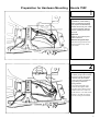
Objective
Installation of the Floating
Mount Saddle Bag hardware
may require the disassembly
and/or removal of your motorcycle's turnsignals, grab bar
mounts, passenger footrests
and seat.
Open seat
Refer to your motorcycle's
owner's manual.
Remove wiring from clips
Pull the wiring from the two
clips located on top of the
rear fender.
2
Disconnect turnsignal wiring
Pull the group of wire connections from under the frame
member and slip the black
cover off of the connections
by pushing it down the
wiring harness.
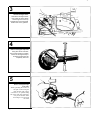
Trace the turnsignal wires
from the turnsignal stalks
and disconnect them at their
bullet connectors. There are
4 black wires: one with a blue
marker, one with an orange,
and two with green markers.
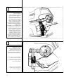
3
3
Unroute turnsignal wires
Unroute the turnsignal wires
from under the frame brace
and through the wire loop
located next to the turnsignal
stalk mount on the grab bar.
4
Remove turnsignal lamp bolts
Using two 10mm wrenches,
remove the bolt and nut which
secure the turnsignal lamp to
its stalk. The bolt must be
completely removed.
5
Remove turnsignal lamps
from stalks
While spreading the surface of
the split on the turnsignal
lamp housing with a large
screwdriver, etc. pull the lamp
off of the stalk and completely
away from the bike while
threading its wire through
the stalk.
4
/
/////z/w,in,////,/q// fi /z/v//////
,//7 I
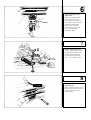
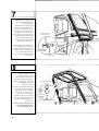
Remove turnsignal stalks
and brackets
Remove the phillips head
screw which secures the
turnsignal stalk to the grab
bar. Pull the stalk away from
the bracket and pull the
bracket down off of the
mounting tab on the grab
bar. Leave the rubber
grommet in place.
7
Remove passenger footrest
Using a 14mm socket, remove
the passenger footrests. The
left side needs no back-up
wrench but the right side
does — use a 14mm wrench.
8
\.%A \
A\ %V
\\\"
Remove grab bar
mounting bolts
Remove the bolts which secure
the grab bar at the rear mounts
(one on each side) with a
12mm wrench.
5
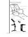
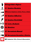
Hardware Parts Nomenclature
LUGGAGE RACK
FORWARD LUGGAGE RACK STRUT
LEFT SIDE LOOP
TURNSIGNAL
STALK
MOUNTING
STUD FUNNEL
TOMAHAWK
VIBRATION ISOLATORS
SIDE LOOP
FORWARD STRUT
TURNSIGNAL STALK (2)
TURNSIGNAL STALK BOLT (2)
MOUNTING STUD ,
FUNNEL
VIBRATION ISOLATORS
6
Metric Scale
1111111 1 11,1111 1 111111 1 111 1 111111
11
11
11
111111111111111111111111111
1
11111111111111111111111
1
11111111111111
1
1111111111111111
1
11111
11
111111
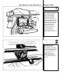
Installation of the Hardware
Honda 750F
1
Objective
The Floating Mount Saddle
Bags are designed to fit a
large number of different
motorcycles. Each model
motorcycle has specially
designed mounting hardware.
When installed properly, the
hardware will locate the saddle
bags at the proper height and
fore and aft location on your
motorcycle. Use all of the
hardware specified and
periodically check for tightness after installation.
Position the side loop •
Start with either side and
position the side loop as shown.
Mount the side loop at
the grab bar mount
While holding the side loop in
place, slide the supplied 8mm x
90mm bolt through the side
loop mounting tab and into
the grab bar mount.
NOTE: A metric scale is
supplied on page 6 for your
ease in identifying different
fasteners.
7
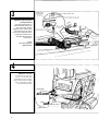
3
Mount the side loop at the
passenger footrest
Use the supplied 10mm x
50mm bolt and 10mm lock
nut on the right and the
supplied 10mm x 40mm bolt
and 10mm lock nut on the
left to secure side loop at the
passenger footrest mount.
Assemble all parts in the
order shown.
NOTE:
Inset drawing shows
right hand side.
4
Mount the rear strut
Locate the rear strut and
secure it to the side loop
tomahawks at the position
shown with 2-6mm x 20mm
bolts, 4-6mm flat washers
and 2-6mm lock nuts.
6mm FLAT
/iWASHER
%11
6mm LOCK NUT
REAR STRUT
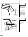
8
Mount luggage rack to
forward luggage rack strut
Positioning the parts as shown,
bolt them together with the
supplied 2-6mm x 30mm lock
bolts and 2-6mm flat washers.
REAR LUGGAGE
RACK STRUT
NOTE: Installation of the
Floating Mount Hardware on
this particular model motorcycle does restrict access to
areas underneath the seat. To
obtain access, the forward
luggage rack strut must be
unbolted from the side loops.
Therefore it is suggested that
you carry your motorcycle's
tool kit in one of the saddle
bags.
Mount the forward luggage
rack strut to the side loops
Using the supplied 2-8mm x
16mm bolts and 2-8mm lock
nuts, secure the forward
luggage rack strut to the
side loop.
9
Mount the rear luggage rack
strut and turnsignal stalks
to the tomahawks.
Mount the rear luggage rack
strut to the tomahawks in the
position shown (the holes in
the upper section of the strut
should line up with those in
the luggage rack) with the two
special turnsignal stalks bolts
and the two supplied turnsignal stalks. Assemble the
parts in the order shown.
Special wiring note: To achieve
a good electrical ground, it is
suggested that you scratch the
surface of the rear luggage rack
strut and tomahawk where
the turnsignal stalk and bolt
contact them.
REAR LUGGAGE
RACK STRUT
TURNSIGNAL
STALK BOLT
8
Mount luggage rack to
luggage rack rear strut
With 2-6mm x 30mm lock
bolts and 2-6mm flat washers,
mount the luggage rack to the
rear luggage rack strut.
LUGGAGE RACK
Electrical hook-up
Run the wire of each turnsignal
( L-orange, R-blue) through its
stalk. Reverse the procedure
in steps 5, 4, 3, 2 and 1 under
Preparation for Hardware
Mounting. Before connecting
the wires together add the 7"
wire extensions. Match colors
and connect.
NOTE: Check turnsignals for
correct operation. Refer to
Troubleshooting, if not.
10
REAR
LUGGAGE
RACK
STRUT
6mm FLAT
WASHER
6mm x 30mm LOCK BOLT
Saddle Bag Parts Nomenclature
RIGHT SADDLE BAG
CARRYING HANDLE
STOP STRAP SNAP
ALUMINUM EXTRUSSION
WITH WEATHERSTRIPPING
SADDLE BAG DOOR
REAR BAG
MOUNTING BRACKET
W/ LOCK
TEXAS TRIM
DOOR LOCK
DOOR STOP STRAP
Saddle Bag Door Mounting
1
Objective
In order to supply saddle bags
of various colors, the doors
are packaged separately and
require a simple mounting
procedure before the bags
are ready for use.
Separate left and right saddle
bags, doors & Texas Trim.
Assemble one bag at a time.
Position door on hinges
Using 2-4mm x 12mm screws,
insert one screw at each hinge
point from the inside of the
door. Position the door on
the hinges.
11
2
Positioning the Texas Trim
Next position the Texas Trim
over the screws (be careful
not to apply too much pressure on the screws or they
will be forced into the bag).
Thread nuts onto
phillips head screws
Now thread the 4mm lock
nuts onto the screws
and tighten.
Unlock the door and insert
the two remaining screws
through the door, hinge and
Texas Trim and thread on
their nuts & tighten.
PHILLIPS HEAD
SCREW
SADDLE
BAG DOOR
ALUMINUM
EXTRUSSION
HINGE
TEXAS TRIM
LOCK NUT
Repeat the above three (3)
steps for the remaining bag.
Mounting Saddle Bag
door lock
To mount the saddle bag door
lock (packaged with the bag)
si mply insert the lock through
the door, slide on the large
star washer and thread on
the nut. Do not overtighten.
Mount the locking cam
straight up when the key lock
is in the locked position
( when the key can be
removed). Assemble the
parts as shown.
Q
0
-Se
'4?
"74
(5,
0*.
"S•
F
-5$ 7
"7
1-
0
PHILLIPS HEAD SCREW
9s
"S'
0
NYLON WASHER
0
12-
SADDLE BAG
Mounting Texas Trim
at rear of bag
Mount the Texas Trim to
each bag at 3 places with
3 black spacers, 3 nylon
washers & 3 phillips head
screws.
12
BLACK SPACER
•
r--TEXAS TRIM
4
Connecting snap of door
stop strap
Snap the door stop strap
into position as shown.
Locking cam adjustment
When locking the door, there
should be a moderate amount
of resistance to key movement.
Too much or too little resistance indicates a need for locking cam adjustment. This is
done by removing the cam,
clamping it in a vise, and
tapping it firmly with a hammer in the appropriate direction to increase or decrease
resistance. Generally, a 10-15
degree bend is sufficient.
Extended use may also
necessitate an adjustment,
in which case, the above
procedure also applies.
Saddle Bag Mounting
1
Objective
Once all of the Floating Mount
Saddle Bag Hardware is
attached to the motorcycle
and the doors and trim are
mounted on the saddle bags,
the saddle bags are ready to be
mounted on the motorcycle.
Mounting the saddle bag at
its forward mount
Starting at the forward mount
insert the mounting stud into
the stud funnel while holding
the bag out at an angle as
shown.
13
2
Mounting the saddle bag
at its rear mount
While holding the forward
mount in position, push the
rear mount of the bag to the
side loop tomahawk. Insert
the conehead into its spring
loaded receptical (an audible
"click" will be heard when
the conehead is fully engaged.)
The bag is now mounted and
ready for use.
CAUTION: To avoid saddle bag
damage from muffler heat, a
minimum clearance of 19mm
('4") is needed. To obtain desireable tail pipe clearance it
may be necessary to loosen
saddle bag hardware: apply
upward pressure then tighten
into place. Follow by loosening
muffler; apply downward pressure to muffler, and retighten.
3
Saddle bag removal
To remove the bag, simply
turn the locking key to its
release position, and pull the
rear of the bag out and back to
disengage the forward mount.
NOTE: If the conehead and/or
latch mechanism become
difficult to operate, a thin
layer of oil on the parts should
correct the problem.
NOTE: Use only powdered
graphite on the locks themselves for lubricant.
14
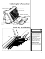
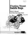
4
Carrying the Floating Mount
Saddle Bags by hand
When carrying the saddle
bags by hand, they are
designed to be carried with
the doors facing you.
1
,„
111111
pplie►tifiaglod
11(141/1„,,
- ____
4111111111
'
SPECIAL NOTE: Vetter Corporation reserves the right to make changes in design and specifications, and/or to
make additions to or improvements in its products without imposing any obligations upon itself to add or install
them on products previously manufactured or sold.
A WARNING
READ CAREFULLY
BEFORE LOADING
THE SADDLEBAGS, TAIL TRUNK AND LUGGAGE RACK ARE FOR LIGHT WEIGHT ITEMS. EXCESSIVE WEIGHT AND IMPROPER LOADING MAY AFFECT MOTORCYCLE STABILITY, DECREASE
SAFE OPERATING SPEED, AND CAUSE MOUNTING HARDWARE OR SADDLEBAG FAILURE.
A
DO NOT EXCEED A COMBINED MAXIMUM LOAD OF 27 KGS. (60 LBS.) IN THE SADDLEBAGS AND
TAIL TRUNK OR ON THE LUGGAGE RACK. DISTRIBUTE THE LOAD EQUALLY ON BOTH SIDES
OF THE MOTORCYCLE. DO NOT EXCEED A MAXIMUM LOAD OF 9 KGS. (20LBS.) FOR EACH
SADDLEBAG.
FACTORS BEYOND OUR CONTROL SUCH AS OPERATOR'S WEIGHT, PASSENGER'S WEIGHT,
WEIGHT OF OTHER ACCESSORIES, ETC. MAY FURTHER REDUCE THE SAFE AMOUNT OF
WEIGHT CARRIED IN OUR SADDLEBAGS AND TAIL TRUNK OR ON THE LUGGAGE RACK.
DO NOT EXCEED YOUR MOTORCYCLE'S VEHICLE CAPACITY LOAD LIMIT AS SHOWN ON ITS
TIRE INFORMATION LABEL AND AGAIN IN YOUR MOTORCYCLE OWNER'S MANUAL.
A
REFER TO THE INSTALLATION INSTRUCTIONS FOR ADDITIONAL INFORMATION. IF YOU
HAVE ANY QUESTIONS CONTACT YOUR DEALER, OR:
CUSTOMER SERVICE DEPT.
VETTER CORPORATION
1150 LAUREL LANE
SAN LUIS OBISPO, CA 93401
(805) 541-2900
CAUTION:
Any non-stock exhaust system mounted on a motorcycle equipped with Vetter
saddle bags must provide a minimum clearance of 25.4mm(1 inch) between any
part of the tail pipe and the bottom of the saddle bags. In addition, exhaust
gases must not be directed toward the saddle bag.
15
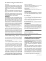
Troubleshooting and Maintenance
ELECTRICAL
If your problem is electrical, check your color code to insure
the proper wires have been connected. A loose bullet connector
connection can be improved by unpluging the connector and
making the female receptacle smaller by use of pliers and then
reinstalling the bullet connector. If your turnsignals do not
function properly, your ground connection is probably not
making good contact, or your battery is weak and needs to be
serviced.
If there are any problems that cannot be solved by you or your
dealer, contact the Customer Service Department of Vetter Corporation, 1150 Laurel Lane, San Luis Obispo, CA 93401
(805) 541-2900.
MOUNTING
The best answer to almost any problem is to reread your instructions carefully. Sometimes it is helpful for someone else to look
the problem over, especially someone who has not been working
on the installation with you, such as your dealer.
MAINTENANCE
The Floating Mount Saddle Bags require little maintenance, but
we recommend that you make periodic checks. The mounting
bolts and mounting clamps should be checked for tightness and
adjustments made as necessary.
Cleaning and waxing the Saddle Bags: When washing your saddle
bags, use a mild detergent and warm water. Washing should be
done with a soft cloth or sponge. Avoid spraying water under
pressure directly at the joint between the door and the body of
the saddle bag as some water may enter the bag itself. Waxing
the saddle bags is easy; furniture polish works as well as anything
we have found. Spray the polish on a rag rather than on the bag
itself, however, as if it is sprayed on the bag the wax becomes
very difficult to remove from the bag's textured surface.
CAUTION: Do not use cleansers which contain methyl or
ethyl alcohol.
CAUTION: Hydraulic fluid will damage your saddle bags. Never
allow it to come in contact with your saddle bags.
With normal use the bodies of your saddle bags may become
scratched or marred. Small cosmetic touch-ups can be accomplished by treating the area with a hot air gun (a hair dryer is not
hot enough) or a propane torch. Using either the torch or the
hot air gun, pass back and forth over the marred area in a sweeping motion at a safe distance from the bag surface. The correct
amount will smooth and restore shine to the damaged area. If
the area in concern is located near the door or a painted part,
that part should be removed before any treatment is performed.
PAINTING INSTRUCTIONS
If you wish to repaint your saddle bag doors, we, recommend
that the following instructions be used:
1. Remove the Floating Mount logo and stripe decals.
2. Sand thoroughly with 320 grit wet sandpaper.
3. Resand with 400 grit wet sandpaper.
4. Dry thoroughly.
5. Spray with Dupont 100S Multi-Purpose Primer.
6. Spray Dupont Weight Lifter Acrylic Enamel with 7925 or
7935 Hardener.
7. Install new vinyl decals.
SADDLE BAG STRIPING
When removing striping from the saddle bag doors, the suggested
method is to use 3M Woodgrain and striping Remover, part
number 08907, followed by 3M Adhesive Remover, part number 08908. Please follow the directions on the spray cans. These
products can be obtained at most paint and automotive stores
that carry 3M products.
When handling saddle bag striping, do not crease or bend it.
Always handle striping from the edges, never from the ends. Do
not pull the backing paper off the striping with expectations of
reapplying. Backing paper will NOT restick.
If you have any questions on storing, handling, removing or
applying of saddle bag striping that your dealer cannot answer,
contact our Customer Service Department.
REPLACEMENT PARTS
We recommend that you always use Genuine Vetter Replacement Parts. Contact your local Vetter dealer to purchase or
order replacement parts.
CUSTOMER SERVICE
Any problems concerning installation of the Saddle Bags should
be referred to your dealer or the Customer Service Department,
Vetter Corporation, 1150 Laurel Lane, San Luis Obispo,
CA 93401. We are here to serve you: (805) 541-2900. In order
to provide the maximum amount of service to you and the dealer, it is necessary that you fill out the Owner's Registration Card
and promptly return it to Vetter Corporation. We also suggest you record your saddle bags Serial number here:
so you'll have it should you ever need to contact us: (It is located
inside the left hand saddle bag.)
Also record your key number hereso that you can order replacement locks if necessary.
Limited Warranty—Vetter Corporation Products
This warranty applies to products manufactured or distributed
by Vetter Corporation, 1150 Laurel Lane, San Luis Obispo, CA
93401, and sold by Vetter Corporation or its authorized dealers
within the United States, Puerto Rico, and the Virgin Islands.
It is given to the first retail purchaser only and is not transferable to subsequent owners.
Warranty Obligation: Vetter Corporation warrants that it,
or one of its authorized dealers, will repair or, at its option,
replace any part proven to be defective in factory material or
workmanship within six (6) months (unlimited mileage) of the
date of purchase. Parts repaired or replaced under this warranty
are warranted only during the balance of the original warranty
period. THIS WARRANTY DOES NOT INCLUDE ANY LABOR
CHARGES FOR TROUBLESHOOTING, REMOVAL OR INSTALLATION.
Exclusions from Coverage: 1. Any repairs or replacements or
parts necessitated by misuse, negligence, fire, accident, damage
caused by exposure to gasoline, brake fluid, harmful solvents
and cleaners, paints, or repair material, use of unauthorized
accessories, faulty installation, installation upon motorcycles or
vehicles not listed in Vetter Corporation's retail and dealer
catalog sheets, or improper or unreasonable maintenance are
not covered. 2. This warranty does not cover "Totes" rainboots.
DISCLAIMER OF CONSEQUENTIAL DAMAGES AND LIMITATIONS OF IMPLIED WARRANTIES: TO THE EXTENT
THE LAW PERMITS, VETTER CORPORATION SHALL
NOT BE LIABLE UNDER ANY CIRCUMSTANCES FOR LOSS
OF USE OF THE PRODUCT, CONSEQUENTIAL OR INCI16 DENTAL DAMAGES. ANY IMPLIED WARRANTY ARISING
UNDER LAW, INCLUDING THOSE OF MERCHANTABILITY
AND FITNESS FOR A PARTICULAR PURPOSE, IS LIMITED
TO THE DURATION OF THIS LIMITED WARRANTY.
I MPORTANT: Some states do not allow limitations on how
long an implied warranty lasts and/or limitations or exclusions
or consequential or incidental damages, so the above limitations
may not apply to you.
To Obtain Warranty Service: Information you must provide
when filing claim: 1. Name, mailing address and telephone
number. 2. Selling dealer's name and address. 3. Serial number
of product. 4. Model and year of motorcycle. 5. Date product
was purchased. 6. Date and mileage at failure. 7. Description of
problem.
Steps to take: 1. Contact or take your product to an authorized
Vetter dealer (preferably your selling dealer) at your expense.
2. If you are unable to obtain warranty service, or should your
warranty claim be denied for reasons that you consider unjustifiable, contact the owner of your selling dealer. Normally, this
should resolve your problem. However, if you require further
assistance, write or call the Customer Service Department of
Vetter Corporation, 1150 Laurel Lane, San Luis Obispo,
CA 93401, (805) 541-2900. At this point, you must be prepared
to return the part in question to Vetter Corporation with
all freight charges prepaid. The charges will be reimbursed to you
if they total over $5.00 (five dollars) and the warranty claim is
honored. This warranty gives you specific legal rights and you
may also have other rights which vary from state to state.
June 23, 1978
Vetter Corporation
140 130 076
oVetter Corp. 1979
4-27-79
Floating Mount
Saddle Bags
Supplement Owner's Manual and Mounting Instructions
1979
Honda 750F
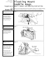
6
NOTE: The 1979 Honda CB750F factory-supplied exhaust is not compatible with the
Floating Mount Saddle Bag system and must be replaced with a suitable substitul
Your dealer can probably suggest an exhaust system which is compatible.
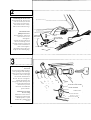
Remove turn signals
Disconnect the turn
signal wires. Remove
the Phillips head screw
securing the stalk to
the tab. Thread the
wiring through the tail
section and remove the
turn signal assembly.
2
Mount side loop
at grab bar mount
While holding the side
loop in place, slide
the stock bolt through
the side loop mounting
bracket and into the
grab bar mount.
7
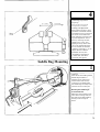
Mount luggage rack
strut
Position the rear
luggage strut, insert
the turn signal mounting
tab through the strut,
tomahawk, flat washer
and into the 12mm lock
nut.
Attach the turn signal
to the mounting tab
with the original Phillips
head screw. Reroute the
wires and connect them
at their designated bullet
connectors.
LOCK NUT
FLAT WASHER
TOMAHAWK
TURN SIGNAL TAB
14 014 0029
C) Vetter Corp. 1979
4-27-79
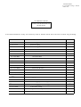
1979 HONDA CB750F
SADDLE BAG HARDWARE KIT
10 006 0123
Packina List
Use this hardware only on motorcycle(s) listed. This list current at time of printing.
DESCRIPTION
Parts#
14 012 0103
Mounting Instructions
15 003 0103
Hardware Bag
15 008 0129
Turn Signal Tab
2
17 024 0041
6x2Omm Bolt
2
- 17 024 0062
6x30mm Bolt
4
17 024 0044
8x2Omm Bolt
2
17 024 0063
10x55mm Bolt
2
17 026 0008
6mm Lock Nut
2
17 026 0009
8mm Lock Nut
2
17 026 0015
12mm Lock Nu
2
17 027 0005
6mm Flat Washer
8
17 027 0006
8mm Flat Washer
4
21 004 0008
Red Reflector
2
17 027 0007
10mm Flat Washer
2
5 0017
12mm Flat Washer
2
-
#
. 1
17
0
-
Luggage Rack
1
15'009 0033
Rear Cross Strut
1
15 012 0010
Rear Luggage Rack Support
1
15 012 0030
Front Luggage Rack Support
15112 0098
Left Side Loop
1
151L2 0099
Right Side Loop
1
14 012 0121
1979 Honda CB750F Supplement
1
15
0203
-
1