1
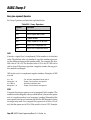
BASIC Stamp II
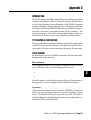
The following section deals with the BASIC Stamp II. In the following
pages, you’ll find installation instructions, programming procedures,
PBASIC2 command definitions, and several application notes.
2
Parallax, Inc. • BASIC Stamp Programming Manual 1.8 • Page 197
BASIC Stamp II
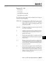
System Requirements
To program the BASIC Stamp II, you’ll need the following computer
system:
•
IBM PC or compatible computer
•
3.5-inch disk drive
•
Serial port
•
128K of RAM
•
MS-DOS 2.0 or greater
If you have the BASIC Stamp II carrier board, you can use a 9-volt
battery as a convenient means to power the BASIC Stamp. You can
also use a 5-15 (5-40 volts on BS2-IC rev. d) volt power supply, but you
should be careful to connect the supply to the appropriate part of the
BASIC Stamp. A 5-volt supply should be connected directly to the +5V
pin, but a higher voltage should be connected to the PWR pin.
Connecting a high voltage supply (greater than 6 volts) to the 5-volt
pin can permanently damage the BASIC Stamp.
Packing List
If you purchased the BASIC Stamp Programming Package, you should
have received the following items:
• BASIC Stamp Programming Manual (this manual)
• BASIC Stamp I programming cable (parallel port DB25-to-3 pin)
• BASIC Stamp II programming cable (serial port DB9-to-DB9)
• BASIC Stamp I and BASIC Stamp II schematics
• 3.5-inch diskette
If any items are missing, please let us know.
Page 198 • BASIC Stamp Programming Manual 1.8 • Parallax, Inc.
BASIC Stamp II
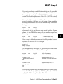
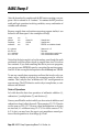
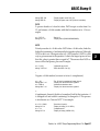
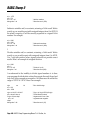
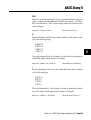
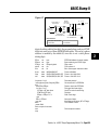
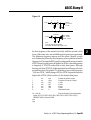
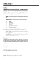
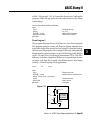
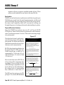
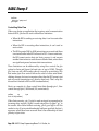
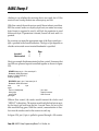
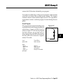
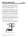
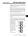
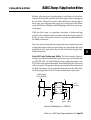
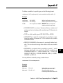
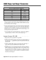
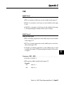
Connecting to the PC
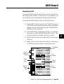
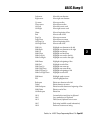
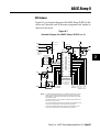
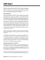
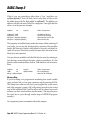
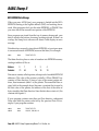
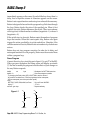
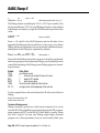
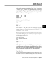
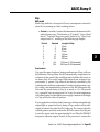
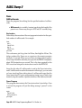
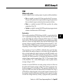
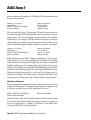
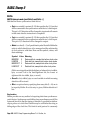
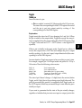
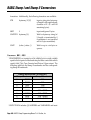
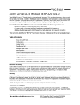
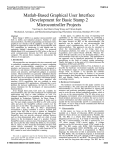
To program a BASIC Stamp II, you’ll need to connect it to your PC and
then run the editor software. In this section, it’s assumed that you
have a BS2-IC and its corresponding carrier board (shown below).
To connect the BASIC Stamp II to your PC, follow these steps:
1) Plug the BS2-IC onto the carrier board. The BS2-IC plugs into
a 24-pin DIP socket, located in the center of the carrier. When
plugged onto the carrier board, the words “Parallax BS2-IC”
should be near the reset button.
2) In the BASIC Stamp Programming Package, you received a
serial cable to connect the BASIC Stamp II to your PC. Plug
the female end into an available serial port on your PC.
3) Plug the male end of the serial cable into the carrier board’s
serial port.
4) Supply power to the carrier board, either by connecting a
9-volt battery or by providing an external power source.
BASIC Stamp II
TM
9-volt
Battery
Clips
Prototyping
Area
RS-232
Serial
Port
BS2-IC
BS2-IC
Socket
TX
RX
ATN
GND
PO
P1
P2
P3
P4
P5
P6
P7
2 3 4 5
Host Serial Port
Reset
Button
Reset
PWR
GND
RES
+5V
P15
P14
P13
P12
P11
P10
P9
P8
I/O
Header
I/O
Header
© 1995
REV A
Parallax, Inc. • BASIC Stamp Programming Manual 1.8 • Page 199
2
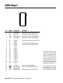
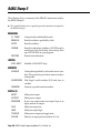
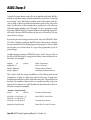
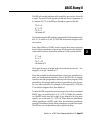
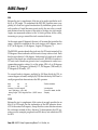
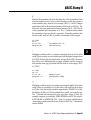
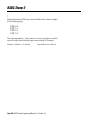
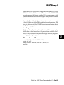
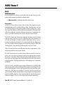
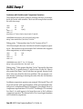
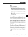
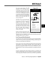
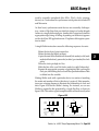
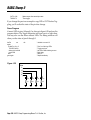
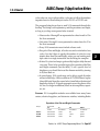
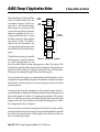
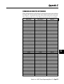
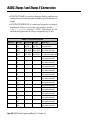
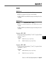
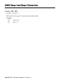
BASIC Stamp II
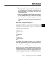
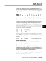
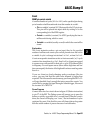
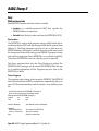
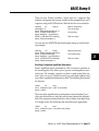
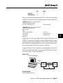
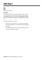
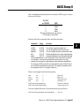
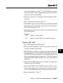
Pin
TX
1
24
PWR
RX
2
23
GND
ATN
3
22
RES
GND
4
21
+5V
P0
5
20
P15
P1
6
19
P14
P2
7
18
P13
P3
8
17
P12
P4
9
16
P11
P5
10
15
P10
P6
11
14
P9
P7
12
13
P8
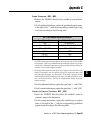
Name
Description
Comments
1
2
3
4
TX
RX
ATN
GND
Serial output
Serial input
Active-high reset
Serial ground
Connect to pin 2 of PC serial DB9 (RX) *
Connect to pin 3 of PC serial DB9 (TX) *
Connect to pin 4 of PC serial DB9 (DTR) *
Connect to pin 5 of PC serial DB9 (GND) *
5
6
7
8
9
10
11
12
13
14
15
16
17
18
19
20
P0
P1
P2
P3
P4
P5
P6
P7
P8
P9
P10
P11
P12
P13
P14
P15
I/O pin 0
I/O pin 1
I/O pin 2
I/O pin 3
I/O pin 4
I/O pin 5
I/O pin 6
I/O pin 7
I/O pin 8
I/O pin 9
I/O pin 10
I/O pin 11
I/O pin 12
I/O pin 13
I/O pin 14
I/O pin 15
Each pin can source 20 ma and sink 25 ma.
21
22
23
24
+5V **
RES
GND
PWR **
+5V supply
Active-low reset
System ground
Regulator input
5-volt input or regulated output.
Pull low to reset; goes low during reset.
P0-P7 and P8-P15, as groups, can each
source a total of 40 ma and sink 50 ma.
* For automatic serial port selection by
the BASIC Stamp II software, there
must also be a connection from DSR
(DB9 pin 6) to RTS (DB9 pin 7). This
connection is made on the BASIC
Stamp II carrier board. If you are not
using the carrier board, then you must
make this connection yourself, or use
the command-line option to tell the
software which serial port to use.
Voltage regulator input; takes 5-15 volts.
Page 200 • BASIC Stamp Programming Manual 1.8 • Parallax, Inc.
** During normal operation, the BASIC
Stamp II takes about 7 mA. In various power-down modes, consumption can be reduced to about 50 µA.
BASIC Stamp II
Starting the Editor
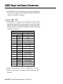
With the BASIC Stamp II connected and powered, insert the BASIC
Stamp diskette and then enter the BASIC Stamp II directory by typing
the following command from the DOS prompt:
CD STAMP2
Once in the BASIC Stamp II directory, you can run the BASIC Stamp II
editor/downloader software by typing the following command:
STAMP2
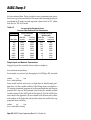
The software will start running after several seconds. The editor screen
is dark blue, with one line across the top that indicates how to get onscreen editor help. Except for the top line, the entire screen is available
for entering and editing PBASIC programs.
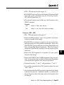
Command-line options:
There are several command-line options that may be useful when running the software; these options are shown below:
STAMP2 filename
Runs the editor and loads filename.
STAMP2 /m
Runs the editor in monochrome mode. May
give a better display on some systems, especially laptop computers.
STAMP2 /n
Runs the editor and specifies which serial port
to use when downloading to the BASIC Stamp
II (note that n must be replaced with a serial
port number of 1-4).
Normally, the software finds the BASIC Stamp II by looking on all serial ports for a connection between DSR and RTS (this connection is
made on the carrier board). If the DSR-RTS connection is not present,
then you must tell the software which port to use, as shown above.
Parallax, Inc. • BASIC Stamp Programming Manual 1.8 • Page 201
2
BASIC Stamp II
Entering & Editing Programs
We’ve tried to make the editor as intuitive as possible: to move up,
press the up arrow; to highlight one character to the right, press shiftright arrow; etc.
Most functions of the editor are easy to use. Using single keystrokes,
you can perform the following common functions:
• Load, save, and run programs.
• Move the cursor in increments of one character, one word, one
line, one screen, or to the beginning or end of a file.
• Highlight text in blocks of one character, one word, one line, one
screen, or to the beginning or end of a file.
• Cut, copy, and paste highlighted text.
• Search for and/or replace text.
• See how the BASIC Stamp II memory is being allocated.
• Identify the version of the PBASIC interpreter.
Editor Function Keys
The following list shows the keys that are used to perform various
functions:
F1
Display editor help screen.
Alt-R
Run program in BASIC Stamp II (download the
program on the screen, then run it)
Alt-L
Alt-S
Alt-M
Alt-I
Alt-Q
Load program from disk
Save program on disk
Show memory usage maps
Show version number of PBASIC interpreter
Quit editor and return to DOS
Enter
Tab
Enter information and move down one line
Same as Enter
Page 202 • BASIC Stamp Programming Manual 1.8 • Parallax, Inc.
BASIC Stamp II
Left arrow
Right arrow
Move left one character
Move right one character
Up arrow
Down arrow
Ctrl-Left
Ctrl-Right
Move up one line
Move down one line
Move left to next word
Move right to next word
Home
End
Page Up
Page Down
Ctrl-Page Up
Ctrl-Page Down
Move to beginning of line
Move to end of line
Move up one screen
Move down one screen
Move to beginning of file
Move to end of file
Shift-Left
Shift-Right
Shift-Up
Shift-Down
Shift-Ctrl-Left
Shift-Ctrl-Right
Highlight one character to the left
Highlight one character to the right
Highlight one line up
Highlight one line down
Highlight one word to the left
Highlight one word to the right
Shift-Home
Shift-End
Shift-Page Up
Shift-Page Down
Shift-Ctrl-Page Up
Shift-Ctrl-Page Down
Highlight to beginning of line
Highlight to end of line
Highlight one screen up
Highlight one screen down
Highlight to beginning of file
Highlight to end of file
Shift-Insert
ESC
Highlight word at cursor
Cancel highlighted text
Backspace
Delete
Shift-Backspace
Shift-Delete
Ctrl-Backspace
Delete one character to the left
Delete character at cursor
Delete from left character to beginning of line
Delete to end of line
Delete line
Alt-X
Alt-C
Alt-V
Cut marked text and place in clipboard
Copy marked text to clipboard
Paste (insert) clipboard text at cursor
Alt-F
Alt-N
Find string (establish search information)
Find next occurrence of string
Parallax, Inc. • BASIC Stamp Programming Manual 1.8 • Page 203
2
BASIC Stamp II
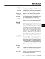
The following list is a summary of the PBASIC instructions used by
the BASIC Stamp II.
◆ This symbol indicates new or greatly improved instructions (compared to
the BASIC Stamp I).
BRANCHING
IF...THEN
Compare and conditionally branch.
BRANCH
Branch to address specified by offset.
GOTO
Branch to address.
GOSUB
Branch to subroutine at address. GOSUBs may be
nested up to four levels deep, and you may have
up to 255 GOSUBs in your program.
RETURN
Return from subroutine.
LOOPING
FOR...NEXT
Establish a FOR-NEXT loop.
NUMERICS
LOOKUP
Lookup data specified by offset and store in variable. This instruction provides a means to make a
lookup table.
LOOKDOWN
Find target’s match number (0-N) and store in
variable.
RANDOM
Generate a pseudo-random number.
DIGITAL I/O
INPUT
Make pin an input
OUTPUT
Make pin an output.
REVERSE
If pin is an output, make it an input. If pin is an
input, make it an output.
LOW
Make pin output low.
HIGH
Make pin output high.
TOGGLE
Make pin an output and toggle state.
PULSIN
Measure an input pulse (resolution of 2 µs).
Page 204 • BASIC Stamp Programming Manual 1.8 • Parallax, Inc.
BASIC Stamp II
PULSOUT
Output a timed pulse by inverting a pin for some
time (resolution of 2 µs).
BUTTON
Debounce button, perform auto-repeat, and branch
to address if button is in target state.
◆
SHIFTIN
Shift bits in from parallel-to-serial shift register.
◆
SHIFTOUT
Shift bits out to serial-to-parallel shift register.
◆
COUNT
Count cycles on a pin for a given amount of time
(0 - 125 kHz, assuming a 50/50 duty cycle).
◆
XOUT
Generate X-10 powerline control codes. For use
with TW523 or TW513 powerline interface module.
SERIAL I/O
◆
◆
SERIN
SEROUT
Serial input with optional qualifiers, time-out, and
flow control. If qualifiers are given, then the instruction will wait until they are received before
filling variables or continuing to the next instruction. If a time-out value is given, then the instruction will abort after receiving nothing for a given
amount of time. Baud rates of 300 - 50,000 are
possible (0 - 19,200 with flow control). Data received must be N81 (no parity, 8 data bits, 1 stop
bit) or E71 (even parity, 7 data bits, 1 stop bit).
Send data serially with optional byte pacing and
flow control. If a pace value is given, then the
instruction will insert a specified delay between
each byte sent (pacing is not available with flow
control). Baud rates of 300 - 50,000 are possible (0
- 19,200 with flow control). Data is sent as N81 (no
parity, 8 data bits, 1 stop bit) or E71 (even parity, 7
data bits, 1 stop bit).
ANALOG I/O
◆
PWM
Output PWM, then return pin to input. This can be
used to output analog voltages (0-5V) using a
capacitor and resistor.
RCTIME
Measure an RC charge/discharge time. Can be
used to measure potentiometers.
Parallax, Inc. • BASIC Stamp Programming Manual 1.8 • Page 205
2
BASIC Stamp II
SOUND
◆
FREQOUT
Generate one or two sinewaves of specified frequencies (each from 0 - 32767 hz.).
◆
DTMFOUT
Generate DTMF telephone tones.
EEPROM ACCESS
◆
DATA
Store data in EEPROM before downloading
PBASIC program.
READ
Read EEPROM byte into variable.
WRITE
Write byte into EEPROM.
TIME
PAUSE
Pause execution for 0–65535 milliseconds.
POWER CONTROL
NAP
Nap for a short period. Power consumption is
reduced.
SLEEP
Sleep for 1-65535 seconds. Power consumption is
reduced to approximately 50 µA.
END
Sleep until the power cycles or the PC connects.
Power consumption is reduced to approximately
50 µA.
PROGRAM DEBUGGING
DEBUG
Send variables to PC for viewing.
Page 206 • BASIC Stamp Programming Manual 1.8 • Parallax, Inc.
BASIC Stamp II
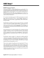
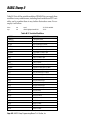
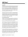
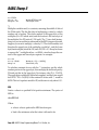
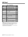
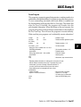
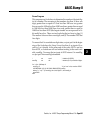
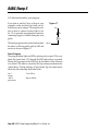
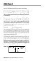
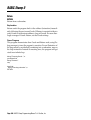
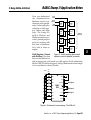
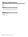
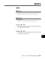
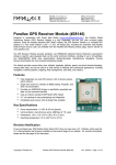
BS2 Hardware
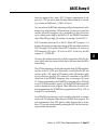
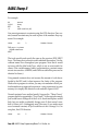
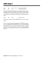
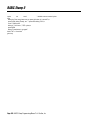
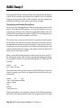
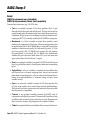
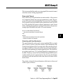
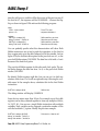
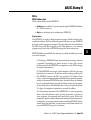
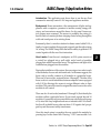
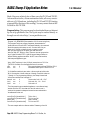
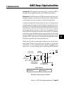
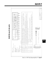
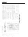
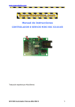
Figure H-1 is a schematic diagram of the BASIC Stamp II (BS2). In this
section we’ll describe each of the major components and explain its
function in the circuit.
Figure H-1
Schematic
Stamp IIII(BS2-IC
(BS2-ICrevA)
rev. A)
SchematicDiagram
Diagram of
of the
the BASIC
BASIC Stamp
+5V
(24)
U4
BS2 components
5V Reg.
U3
Vdd
S-81350HG
+
Vss
U1 PBASIC2
+5V
+5V
2kB EEPROM
1
NC
2
NC
3
NC
4
Vss
24LC16B
U2
1
RTCC
MCLR 28
2
Vdd
OSC1 27
3
NC
OSC2 26
4
Vss
5
NC
SCL 6
6
RA0
SDA 5
7
RA1
8
RA2
9
RA3
VDD 8
WP 7
4.7k
+5V
10 RB0
4.7k
11 RB1
12 RB2
SIN
(2)
Q1
10k
OUT
Vss
22µF
10V
(23, 4)
*Also called “ground”
throughout this
document.
4.7k
4V Reset
S-8054HN
Q2
20-MHz
Ceramic
Resonator
CSTCS
20.00
VIN
PBASIC2 Interpreter Chip
(Parallax Custom PIC16C57)
(21)
*VSS
+5V
+5V
Power source for all
VDD
10k
(22)
RES
(3)
ATN
10k
1/2 UMH11TN
RC7 25
RC6 24
RC5 23
RC4 22
RC3 21
RC2 20
RC1 19
RC0 18
RB7 17
13 RB3
RB6 16
14 RB4
RB5 15
10k
1/2 UMH11TN
Input/Output Pins
+5V
10k
SOUT
(1)
DTA114EETL
NOTES
P0 (5)
P1 (6)
P2 (7)
P3 (8)
P4 (9)
10k
Q3
Input: leakage < 1µA
threshold 1.4V
P5 (10)
P6 (11)
P7 (12)
P8 (13)
P9 (14)
P10 (15)
P11 (16)
P12 (17)
P13 (18)
P14 (19)
P15 (20)
Output: source 20mA each
sink 25mA each
4.7k
1. This diagram depicts the DIP/SOIC version of the PBASIC2 interpreter chip, since users
wishing to construct a BS2 from discrete components are most likely to use those parts.
Contact Parallax for a schematic depicting the SSOP (ultra-small surface mount) package
used in the BS2-IC module.
2. Numbers in parentheses—(#)—are pin numbers on the BS2-IC module. The BS2-IC has
the form factor of a 24-pin, 0.6" DIP.
3. Q1, Q2 and Q3 are Rohm part numbers. Other components may be substituted in custom
circuits, subject to appropriate design. Contact Parallax for design assistance.
4. U3 and U4 are Seiko part numbers. Other components may be substituted in custom
circuits, subject to appropriate design. Contact Parallax for design assistance.
Parallax, Inc. • BASIC Stamp Programming Manual 1.8 • Page 207
2
BASIC Stamp II
PBASIC2 Interpreter Chip (U1)
The brain of the BS2 is a custom PIC16C57 microcontroller (U1). U1 is
permanently programmed with the PBASIC2 instruction set. When you
program the BS2, you are telling U1 to store symbols, called tokens, in
EEPROM memory (U2). When your program runs, U1 retrieves tokens from memory (U2), interprets them as PBASIC2 instructions, and
carries out those instructions.
U1 executes its internal program at 5 million instructions per second.
Many internal instructions go into a single PBASIC2 instruction, so
PBASIC2 executes more slowly—approximately 3000 to 4000 instructions per second.
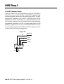
The PIC16C57 controller has 20 input/output (I/O) pins; in the BS2
circuit, 16 of these are available for general use by your programs. Two
others may also be used for serial communication. The remaining two
are used solely for interfacing with the EEPROM and may not be used
for anything else.
The general-purpose I/O pins, P0 through P15, can interface with all
modern 5-volt logic, from TTL (transistor-transistor logic) through
CMOS (complementary metal-oxide semiconductor). To get technical,
their properties are very similar to those of 74HCTxxx-series logic devices.
The direction—input or output—of a given pin is entirely under the
control of your program. When a pin is an input, it has very little effect
on circuits connected to it, with less than 1 microampere (µA) of current leaking in or out. You may be familiar with other terms for input
mode like tristate, high-impedance, or hi-Z.
There are two purposes for putting a pin into input mode: (1) To passively read the state (1 or 0) of the pin as set by external circuitry, or (2)
To disconnect the output drivers from the pin. For lowest current draw,
inputs should always be as close to +5V or ground as possible. They
should not be allowed to float. Unused pins that are not connected to
circuitry should be set to output.
Page 208 • BASIC Stamp Programming Manual 1.8 • Parallax, Inc.
BASIC Stamp II
When a pin is an output, it is internally connected to ground or +5V
through a very efficient CMOS switch. If it is lightly loaded (< 1mA),
the output voltage will be within a few millivolts of the power supply
rail (ground for 0; +5V for 1). Pins can sink as much as 25mA (outputting 0) and source up to 20 mA (outputting 1). Each of the two eightpin ports should not carry more than a total of 50mA (sink) or 40mA
(source). Pins P0 through P7 make up one port; P8 through P15 the
other.
2048-byte Erasable Memory Chip (U2)
U1 is permanently programmed at the factory and cannot be reprogrammed, so your PBASIC2 programs must be stored elsewhere. That’s
the purpose of U2, the 24LC16B electrically erasable, programmable
read-only memory (EEPROM). EEPROM is a good medium for program storage because it retains data without power, but can be reprogrammed easily.
EEPROMs have two limitations: (1) They take a relatively long time
(as much as several milliseconds) to write data into memory, and (2)
There is a limit to the number of writes (approximately 10 million)
they will accept before wearing out. Because the primary purpose of
the BS2’s EEPROM is program storage, neither of these is normally a
problem. It would take many lifetimes to write and download 10 million PBASIC2 programs! However, when you use the PBASIC2 Write
instruction to store data in EEPROM space be sure to bear these limitations in mind.
Reset Circuit (U3)
When you first power up the BS2, it takes a fraction of a second for the
supply to reach operating voltage. During operation, weak batteries,
varying input voltages or heavy loads may cause the supply voltage to
wander out of acceptable operating range. When this happens, normally infallible processor and memory chips (U1 and U2) can make
mistakes or lock up. To prevent this, U1 must be stopped and reset
until the supply stabilizes. That is the job of U3, the S-8045HN reset
circuit. When the supply voltage is below 4V, U3 puts a logic low on
U1’s master-clear reset (MCLR) input. This stops U1 and causes all of
its I/O lines to electrically disconnect. In reset, U1 is dormant; alive
but inert.
Parallax, Inc. • BASIC Stamp Programming Manual 1.8 • Page 209
2
BASIC Stamp II
When the supply voltage is above 4V, U3 allows its output to be pulled
high by a 4.7k resistor to +5V, which also puts a high on U1’s MCLR
input. U1 starts its internal program at the beginning, which in turn
starts your PBASIC2 program from the beginning.
Power Supply (U4)
The previous discussion of the reset circuit should give you some idea
of how important a stable power supply is to correct operation of the
BS2. The first line of defense against power-supply problems is U4, the
S-81350HG 5-volt regulator. This device accepts a range of slightly over
5V up to 15V and regulates it to a steady 5V. This regulator draws minimal current for its own use, so when your program tells the BS2 to go
into low-power Sleep, End or Nap modes, the total current draw averages out to approximately 100 microamperes (µA). (That figure assumes
no loads are being driven and that all I/O pins are at ground or +5V.)
When the BS2 is active, it draws approximately 8mA. Since U4 can
provide up to 50mA, the majority of its capacity is available for powering your custom circuitry.
Circuits requiring more current than U4 can provide may incorporate
their own 5V supply. Connect this supply to VDD and leave U4’s input
(VIN) open.
Note that figure H-1 uses CMOS terms for the power supply rails, VDD
for the positive supply and VSS for ground or 0V reference. These terms
are correct because the main components are CMOS. Don’t be concerned that other circuits you may come across use different nomenclature; for our purposes, the terms V DD, VCC, and +5V are interchangeable, as are VSS, earth (British usage) and ground.
Serial Host Interface (Q1, Q2, and Q3)
The BS2 has no keyboard or monitor, so it relies on PC-based host software to allow you to write, edit, download and debug PBASIC2 programs. The PC communicates with the BS2 through an RS-232 (COM
port) interface consisting of pins SIN, SOUT, and ATN (serial in, serial
out, and attention, respectively).
RS-232 uses two signaling voltages to represent the logic states 0 and 1;
+12V is 0 and –12V is 1. When an RS-232 sender has nothing to say, it
Page 210 • BASIC Stamp Programming Manual 1.8 • Parallax, Inc.
BASIC Stamp II
leaves its output in the 1 state (-12V). To begin a transmission, it outputs a 0 (+12V) for one bit time (the baud rate divided into 1 second;
e.g., bit time for 2400 baud = 1/2400 = 416.6µs).
You can see how the BS2 takes advantage of these characteristics in the
design of its serial interface. NPN transistor Q1 serves as a serial line
receiver. When SIN is negative, Q1 is switched off, so the 4.7k resistor
on its collector puts a high on pin RA2 of U1, the PBASIC2 interpreter
chip. When SIN goes high, Q1 switches on, putting a 0 on RA2/U1.
SOUT transmits data from U1 to the PC. When SOUT outputs a 1, it
borrows the negative resting-state voltage of SIN and reflects it back to
SOUT through a 4.7k resistor. When SOUT transmits a 0, it turns on
PNP transistor Q3 to put a +5V level on SOUT. In this way the BS2
outputs +5/–12V RS-232.
Of course, this method works only with the cooperation of the PC software, which must not transmit serial data at the same time the BS2 is
transmitting.
The ATN line interfaces with the data-terminal ready (DTR) handshaking line of the PC COM port. Electrically, it works like the SIN line
receiver, with a +12V signal at ATN turning on the Q2 transistor, pulling its collector to ground. Q2’s collector is connected to the MCLR
(reset) line of the PBASIC2 interpreter chip, so turning on Q2 resets
U1. During programming, the STAMP2 host program pulses ATN high
to reset U1, then transmits a signal to U1 through SIN indicating that it
wants to download a new program. Other than when it wants to initiate programming, the STAMP2 host program holds ATN at –12V, allowing U1 to run normally.
Your PBASIC2 programs may use the serial host interface to communicate with PC programs other than the STAMP2 host program. The
only requirement is that ATN must be either disconnected or at less
than +1V to avoid unintentionally resetting the BS2. See the Serin listing for further information.
Parallax, Inc. • BASIC Stamp Programming Manual 1.8 • Page 211
2
BASIC Stamp II
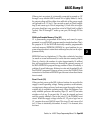
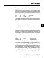
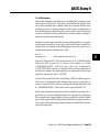
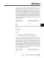
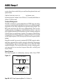
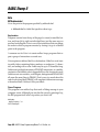
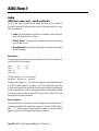
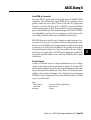
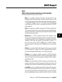
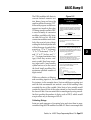
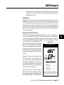
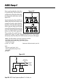
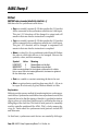
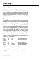
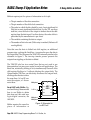
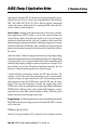
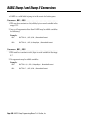
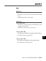
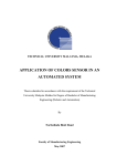
PC-to-BS2 Connector Hookup
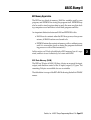
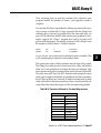
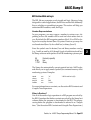
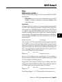
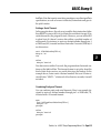
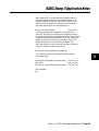
Figure H-2 shows how a DB9 programming connector for the BS2 is
wired. This connector allows the PC to reset the BS2 for programming,
download programs, and receive Debug data from the BS2. An additional pair of connections, pins 6 and 7 of the DB9 socket, lets the
STAMP2 host software identify the port to which the BS2 is connected.
If you plan to construct your own carrier board or make temporary
programming connections to a BS2 on a prototyping board, use this
drawing as a guide. If you also want to use this host interface connection to communicate between the BS2 and other PC programs, see the
writeup in the Serin listing for suggestions.
Figure H-2
BS2 Pin (#)
Rx
Tx
DTR
GND
1
2
6
DSR
3
7
4
8
SOUT (1)
SIN (2)
ATN (3)
VSS (4)
5
9
RTS
Page 212 • BASIC Stamp Programming Manual 1.8 • Parallax, Inc.
BASIC Stamp II
BS2 Memory Organization
The BS2 has two kinds of memory; RAM for variables used by your
program, and EEPROM for storing the program itself. EEPROM may
also be used to store long-term data in much the same way that desktop computers use a hard drive to hold both programs and files.
An important distinction between RAM and EEPROM is this:
• RAM loses its contents when the BS2 loses power; when power
returns, all RAM locations are cleared to 0s.
• EEPROM retains the contents of memory, with or without power,
until it is overwritten (such as during the program-downloading process or with a Write instruction.)
In this section, we’ll look at both kinds of BS2 memory, how it’s organized, and how to use it effectively. Let’s start with RAM.
BS2 Data Memory (RAM)
The BS2 has 32 bytes of RAM. Of these, 6 bytes are reserved for input,
output, and direction control of the 16 input/output (I/O) pins. The
remaining 26 bytes are available for use as variables.
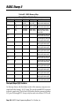
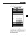
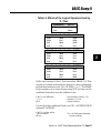
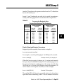
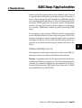
The table below is a map of the BS2’s RAM showing the built-in PBASIC
names.
Parallax, Inc. • BASIC Stamp Programming Manual 1.8 • Page 213
2
BASIC Stamp II
Table M-1. BS2 Memory Map
Stamp II I/O and Variable Space
Word Name
INS
OUTS
DIRS
W0
W1
W2
W3
W4
W5
W6
W7
W8
W9
W10
W11
W12
Byte Name
INL
INH
OUTL
OUTH
DIRL
DIRH
Nibble Names
INA, INB,
INC, IND
OUTA, OUTB,
OUTC, OUTD
DIRA, DIRB,
DIRC, DIRD
B0
B1
B2
B3
B4
B5
B6
B7
B8
B9
B10
B11
B12
B13
B14
B15
B16
B17
B18
B19
B20
B21
B22
B23
B24
B25
Bit Names
IN0 - IN7,
IN8 - IN15
OUT0 - OUT7,
OUT8 - OUT15
DIR0 - DIR7,
DIR8 - DIR15
Special Notes
Input pins; word, byte,
nibble and bit addressable.
Output pins; word, byte,
nibble and bit addressable.
I/O pin direction control;
word, byte, nibble and bit
addressable.
General Purpose; word, byte,
nibble and bit addressable.
General Purpose; word, byte,
nibble and bit addressable.
General Purpose; word, byte,
nibble and bit addressable.
General Purpose; word, byte,
nibble and bit addressable.
General Purpose; word, byte,
nibble and bit addressable.
General Purpose; word, byte,
nibble and bit addressable.
General Purpose; word, byte,
nibble and bit addressable.
General Purpose; word, byte,
nibble and bit addressable.
General Purpose; word, byte,
nibble and bit addressable.
General Purpose; word, byte,
nibble and bit addressable.
General Purpose; word, byte,
nibble and bit addressable.
General Purpose; word, byte,
nibble and bit addressable.
General Purpose; word, byte,
nibble and bit addressable.
The Input/Output (I/O) Variables
As the map shows, the first three words of the memory map are associated with the Stamp’s 16 I/O pins. The word variable INS is unique
in that it is read-only. The 16 bits of INS reflect the bits present at Stamp
I/O pins P0 through P15. It may only be read, not written. OUTS con-
Page 214 • BASIC Stamp Programming Manual 1.8 • Parallax, Inc.
BASIC Stamp II
tains the states of the 16 output latches. DIRS controls the direction
(input or output) of each of the 16 pins.
If you are new to devices that can change individual pins between input and output, the INS/OUTS/DIRS trio may be a little confusing, so
we’ll walk through the possibilities.
A 0 in a particular DIRS bit makes the corresponding pin, P0 through
P15, an input. So if bit 5 of DIRS is 0, then P5 is an input. A pin that is an
input is at the mercy of circuitry outside the Stamp; the Stamp cannot
change its state. When the Stamp is first powered up, all memory locations are cleared to 0, so all pins are inputs (DIRS = %0000000000000000).
A 1 in a DIRS bit makes the corresponding pin an output. This means
that the corresponding bit of OUTS determines that pin’s state.
Suppose all pins’ DIRS are set to output (1s) and you look at the contents of INS. What do you see? You see whatever is stored in the variable OUTS.
OK, suppose all pins’ DIRS are set to input (0s) and external circuits
connected to the pins have them all seeing 0s. What happens to INS if
you write 1s to all the bits of OUTS? Nothing. INS will still contain 0s,
because with all pins set to input, the external circuitry is in charge.
However, when you change DIRS to output (1s), the bits stored in OUTS
will appear on the I/O pins.
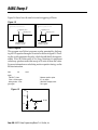
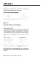
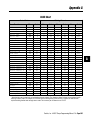
These possibilities are summarized in the Figure M-1 below. To avoid
making the table huge, we’ll look at only one bit. The rules shown for
a single bit apply to all of the I/O bits/pins. Additionally, the external
circuitry producing the “external state” listed in the table can be overridden by a Stamp output. For example, a 10k resistor to +5V will place
a 1 on an input pin, but if that pin is changed to output and cleared to
0, a 0 will appear on the pin, just as the table shows. However, if the
pin is connected directly to +5V and changed to output 0, the pin’s
state will remain 1. The Stamp simply cannot overcome a direct short,
and will probably be damaged in the bargain.
Parallax, Inc. • BASIC Stamp Programming Manual 1.8 • Page 215
2
BASIC Stamp II
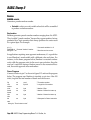
Figure M-1. Interaction of DIRS, INS and OUTS
The DIRS register controls which I/O pins are inputs and which are outputs. When
set to input (0), the corresponding bit in the OUTS register is disconnected and
ignored.
When set to output (1), the corresponding bit in the OUTS register is connected.
NOTE: “X” indicates state could be a 1 or a 0 and does not affect other elements.
“?” indicates state is unknown and could change erratically.
To summarize: DIRS determines whether a pin’s state is set by external circuitry (input, 0) or by the state of OUTS (output, 1). INS always
matches the actual states of the I/O pins, whether they are inputs or
outputs. OUTS holds bits that will only appear on pins whose DIRS
bits are set to output.
In programming the BS2, it’s often more convenient to deal with individual bytes, nibbles or bits of INS, OUTS and DIRS rather than the
entire 16-bit words. PBASIC2 has built-in names for these elements,
listed below. When we talk about the low byte of these words, we mean
the byte corresponding to pins P0 through P7.
Table M-2. Predefined Names for Elements of DIRS, INS and OUTS
DIRS
INS
OUTS
The entire 16-bit word
DIRL
INL
OUTL
The low byte of the word
DIRH
INH
OUTH
The high byte of the word
DIRA
INA
OUTA
The low nibble of low byte
DIRB
INB
OUTB
The high nibble of low byte
DIRC
INC
OUTC
The low nibble of high byte
DIRD
IND
OUTD
The high nibble of high byte
IN0
OUT0
DIR0
DIR15
The low bit; corresponds to P0
...(continues 1 through 14)...
Bits 1 - 14; corresponds to P1 through P14
IN15
The high bit; corresponds to P15
OUT15
Page 216 • BASIC Stamp Programming Manual 1.8 • Parallax, Inc.
BASIC Stamp II
Using the names listed above, you can access any piece of any I/O
variables. And as we’ll see in the next section, you can use modifiers to
access any piece of any variable.
Predefined “Fixed” Variables
As table M-1 shows, the BS2’s memory is organized into 16 words of
16 bits each. The first three words are used for I/O. The remaining 13
words are available for use as general purpose variables.
Just like the I/O variables, the user variables have predefined names:
W0 through W12 and B0 through B25. B0 is the low byte of W0; B1 is
the high byte of W0; and so on through W12 (B24=low byte, B25=high
byte).
Unlike I/O variables, there’s no reason that your program variables
have to be stuck in a specific position in the Stamp’s physical memory.
A byte is a byte regardless of its location. And if a program uses a mixture of variables of different sizes, it can be a pain in the neck to logically dole them out or allocate storage.
More importantly, mixing fixed variables with automatically allocated
variables (discussed in the next section) is an invitation to bugs. A fixed
variable can overlap an allocated variable, causing data meant for one
variable to show up in another!
We recommend that you avoid using the fixed variables in most situations. Instead, let PBASIC2 allocate variables as described in the next
section. The host software will organize your storage requirements to
make optimal use of the available memory.
Why have fixed variables at all? First, for a measure of compatibility
with the BS1, which has only fixed variables. Second, for power users
who may dream up some clever hack that requires the use of fixed
variables. You never know...
Defining and Using Variables
Before you can use a variable in a PBASIC2 program you must declare
it. “Declare” is jargon for letting the Stamp know that you plan to use
a variable, what you want to call it, and how big it is. Although PBASIC
Parallax, Inc. • BASIC Stamp Programming Manual 1.8 • Page 217
2
BASIC Stamp II
does have predefined variables that you can use without declaring them
first (see previous section), the preferred way to set up variables is to
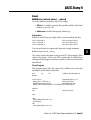
use the directive VAR. The syntax for VAR is:
symbol
VAR
size
where:
• Symbol is the name by which you will refer to the variable. Names
must start with a letter, can contain a mixture of letters, numbers,
and underscore (_) characters, and must not be the same as
PBASIC keywords or labels used in your program. Additionally,
symbols can be up to 32 characters long. See Appendix B for a list
of PBASIC keywords. PBASIC does not distinguish between
upper and lower case, so the names MYVARIABLE, myVariable,
and MyVaRiAbLe are all equivalent.
• Size establishes the number of bits of storage the variable is to
contain. PBASIC2 gives you a choice of four sizes:
bit (1 bit)
nib (nibble; 4 bits)
byte (8 bits)
word (16 bits)
Optionally, specifying a number within parentheses lets you define a
variable as an array of bits, nibs, bytes, or words. We’ll look at arrays
later on.
Here are some examples of variable declarations using VAR:
‘ Declare variables.
mouse
var
cat
var
dog
var
rhino
var
bit
nib
byte
word
‘ Value can be 0 or 1.
‘ Value in range 0 to 15.
‘ Value in range 0 to 255.
‘ Value in range 0 to 65535.
A variable should be given the smallest size that will hold the largest
value that might ever be stored in it. If you need a variable to hold the
on/off status (1 or 0) of switch, use a bit. If you need a counter for a
FOR/NEXT loop that will count from 1 to 10, use a nibble. And so on.
Page 218 • BASIC Stamp Programming Manual 1.8 • Parallax, Inc.
BASIC Stamp II
If you assign a value to a variable that exceeds its size, the excess bits
will be lost. For example, suppose you use the nibble variable cat from
the example above and write cat = 91 (%1011011 binary), what will cat
contain? It will hold only the lowest 4 bits of 91—%1011 (11 decimal).
You can also define multipart variables called arrays. An array is a
group of variables of the same size, and sharing a single name, but
broken up into numbered cells. You can define an array using the following syntax:
symbol
VAR
size(n)
where symbol and size are the same as for normal variables. The new
element, (n), tells PBASIC how many cells you want the array to have.
For example:
myList
var
byte(10)
‘ Create a 10-byte array.
Once an array is defined, you can access its cells by number. Numbering starts at 0 and ends at n–1. For example:
myList(3) = 57
debug ? myList(3)
The debug instruction will display 57. The real power of arrays is that
the index value can be a variable itself. For example:
myBytes
index
var
var
byte(10)
nib
‘ Define 10-byte array.
‘ Define normal nibble variable.
For index = 0 to 9
myBytes(index)= index*13
Next
‘ Repeat with index= 0,1,2...9
‘ Write index*13 to each cell of array.
For index = 0 to 9
debug ? myBytes(index)
Next
stop
‘ Repeat with index= 0,1,2...9
‘ Show contents of each cell.
If you run this program, Debug will display each of the 10 values stored
in the cells of the array: myBytes(0) = 0*13 = 0, myBytes(0) = 1*13 = 13,
myBytes(2) = 2*13 = 26...myBytes(9) = 9*13 = 117.
Parallax, Inc. • BASIC Stamp Programming Manual 1.8 • Page 219
2
BASIC Stamp II
A word of caution about arrays: If you’re familiar with other BASICs
and have used their arrays, you have probably run into the “subscript
out of range” error. Subscript is another term for the index value. It’s
‘out of range’ when it exceeds the maximum value for the size of the
array. For instance, in the example above, myBytes is a 10-cell array.
Allowable index numbers are 0 through 9. If your program exceeds
this range, PBASIC2 will not respond with an error message. Instead, it
will access the next RAM location past the end of the array. This can
cause all sorts of bugs.
If accessing an out-of-range location is bad, why does PBASIC2 allow
it? Unlike a desktop computer, the BS2 doesn’t always have a display
device connected to it for displaying error messages. So it just continues the best way it knows how. It’s up to the programmer (you!) to
prevent bugs.
Another unique property of PBASIC2 arrays is this: You can refer to
the 0th cell of the array by using just the array’s name without an index value. For example:
myBytes
var
myBytes(0) = 17
byte(10)
debug ? myBytes(0)
debug ? myBytes
‘ Define 10-byte array.
‘ Store 17 to 0th cell.
‘ Display contents of 0th cell.
‘ Also displays contents of 0th cell.
This works with the string capabilities of the Debug and Serout
instructions. A string is a byte array used to store text. A string must
include some indicator to show where the text ends. The indicator can
be either the number of bytes of text, or a marker (usually a byte containing 0; also known as a null) located just after the end of the text.
Here are a couple of examples:
‘ Example 1 (counted string):
myText
var
byte(10)
‘ An array to hold the string.
myText(0) = “H”:myText(1) = “E”
myText(2) = “L”:myText(3) = “L”
myText(4) = “0”:myText(9) = 5
‘ Store “HELLO” in first 5 cells...
‘ Put length (5) in last cell*
debug str myText\myText(9)
‘ Show “HELLO” on the PC screen.
Page 220 • BASIC Stamp Programming Manual 1.8 • Parallax, Inc.
BASIC Stamp II
‘ Example 2 (null-terminated string):
myText
var
byte(10)
‘ An array to hold the string.
myText(0) = “H”:myText(1) = “E”
myText(2) = “L”:myText(3) = “L”
myText(4) = “0”:myText(5) = 0
‘ Store “HELLO” in first 5 cells...
‘ Put null (0) after last character.
debug str myText
‘ Show “HELLO” on the PC screen.
(*Note to experienced programmers: Counted strings normally store
the count value in their 0th cell. This kind of string won’t work with
the STR prefix of Debug and Serout. STR cannot be made to start reading at cell 1; debug str myText(1) causes a syntax error. Since arrays
have a fixed length anyway, it does no real harm to put the count in the
last cell.)
Aliases and Variable Modifiers
An alias variable is an alternative name for an existing variable. For
example:
cat
tabby
var
var
nib
cat
‘ Assign a 4-bit variable.
‘ Another name for the same 4 bits.
In that example, tabby is an alias to the variable cat. Anything stored in
cat shows up in tabby and vice versa. Both names refer to the same
physical piece of RAM. This kind of alias can be useful when you want
to reuse a temporary variable in different places in your program, but
also want the variable’s name to reflect its function in each place. Use
caution, because it is easy to forget about the aliases. During debugging, you’ll end up asking ‘how did that value get here?!’ The answer
is that it was stored in the variable’s alias.
An alias can also serve as a window into a portion of another variable.
Here the alias is assigned with a modifier that specifies what part:
rhino
head
tail
var
var
var
word
rhino.highbyte
rhino.lowbyte
‘ A 16-bit variable.
‘ Highest 8 bits of rhino.
‘ Lowest 8 bits of rhino.
Given that example, if you write the value %1011000011111101 to rhino,
then head would contain %10110000 and tail %11111101.
Parallax, Inc. • BASIC Stamp Programming Manual 1.8 • Page 221
2
BASIC Stamp II
Table M-3 lists all the variable modifiers. PBASIC2 lets you apply these
modifiers to any variable name, including fixed variables and I/O variables, and to combine them in any fashion that makes sense. For example, it will allow:
rhino
eye
var
var
word
rhino.highbyte.lownib.bit1
‘ A 16-bit variable.
‘ A bit.
Table M-3. Variable Modifiers
SYMBOL
DEFINITION
LOWBYTE
‘low byte of a word
HIGHBYTE
‘high byte of a word
BYTE0
‘byte 0 (low byte) of a word
BYTE1
‘byte 1 (high byte) of a word
LOWNIB
‘low nibble of a word or byte
HIGHNIB
‘high nibble of a word or byte
NIB0
‘nib 0 of a word or byte
NIB1
‘nib 1 of a word or byte
NIB2
‘nib 2 of a word
NIB3
‘nib 3 of a word
LOWBIT
‘low bit of a word, byte, or nibble
HIGHBIT
‘high bit of a word, byte, or nibble
BIT0
‘bit 0 of a word, byte, or nibble
BIT1
‘bit 1 of a word, byte, or nibble
BIT2
‘bit 2 of a word, byte, or nibble
BIT3
‘bit 3 of a word, byte, or nibble
BIT4
‘bit 4 of a word or byte
BIT5
‘bit 5 of a word or byte
BIT6
‘bit 6 of a word or byte
BIT7
‘bit 7 of a word or byte
BIT8
‘bit 8 of a word
BIT9
‘bit 9 of a word
BIT10
‘bit 10 of a word
BIT11
‘bit 11 of a word
BIT12
‘bit 12 of a word
BIT13
‘bit13 of a word
BIT14
‘bit14 of a word
BIT15
‘bit15 of a word
Page 222 • BASIC Stamp Programming Manual 1.8 • Parallax, Inc.
BASIC Stamp II
The commonsense rule for combining modifiers is that they must get
progressively smaller from left to right. It would make no sense to
specify, for instance, the low byte of a nibble, because a nibble is smaller
than a byte! And just because you can stack up modifiers doesn’t mean
that you should unless it is the clearest way to express the location of
the part you want get at. The example above might be improved:
rhino
eye
var
var
word
rhino.bit9
‘ A 16-bit variable.
‘ A bit.
Although we’ve only discussed variable modifiers in terms of creating
alias variables, you can also use them within program instructions.
Example:
rhino
head
var
var
word
rhino.highbyte
rhino = 13567
debug ? head
debug ? rhino.highbyte
stop
‘ A 16-bit variable.
‘ Highest 8 bits of rhino.
‘ Show the value of alias variable head.
‘ rhino.highbyte works too.
You’ll run across examples of this usage in application notes and sample
programs—it’s sometimes easier to remember one variable name and
specify parts of it within instructions than to define and remember
names for the parts.
Modifiers also work with arrays; for example:
myBytes
var
byte(10)
myBytes(0) = $AB
debug hex ? myBytes.lownib(0)
debug hex ? myBytes.lownib(1)
‘ Define 10-byte array.
‘ Hex $AB into 0th byte
‘ Show low nib ($B)
‘ Show high nib ($A)
If you looked closely at that example, you probably thought it was a
misprint. Shouldn’t myBytes.lownib(1) give you the low nibble of byte
1 of the array rather than the high nibble of byte 0? Well, it doesn’t. The
modifier changes the meaning of the index value to match its own size.
In the example above, when myBytes() is addressed as a byte array, it
has 10 cells numbered 0 through 9. When it is addressed as a nibble
array, using myBytes.lownib(), it has 20 cells numbered 0 through 19.
You could also address it as individual bits using myBytes.lowbit(), in
which case it would have 80 cells numbered 0 through 79.
Parallax, Inc. • BASIC Stamp Programming Manual 1.8 • Page 223
2
BASIC Stamp II
What if you use something other than a “low” modifier, say
myBytes.highnib()? That will work, but its only effect will be to start
the nibble array with the high nibble of myBytes(0). The nibbles you
address with this nib array will all be contiguous—one right after the
other—as in the previous example.
myBytes
var
byte(10)
myBytes(0) = $AB
myBytes(1) = $CD
debug hex ? myBytes.highnib(0)
debug hex ? myBytes.highnib(1)
‘ Define 10-byte array.
‘ Hex $AB into 0th byte
‘ Hex $CD into next byte
‘ Show high nib of cell 0 ($A)
‘ Show next nib ($D)
This property of modified arrays makes the names a little confusing. If
you prefer, you can use the less-descriptive versions of the modifier
names; bit0 instead of lowbit, nib0 instead of low nib, and byte0 instead of low byte. These have exactly the same effect, but may be less
likely to be misconstrued.
You may also use modifiers with the 0th cell of an array by referring to
just the array name without the index value in parentheses. It’s fair
game for aliases and modifiers, both in VAR directives and in instructions:
myBytes
var
zipBit
var
debug ? myBytes.lownib
byte(10)
myBytes.lowbit
‘ Define 10-byte array.
‘ Bit 0 of myBytes(0).
‘ Show low nib of 0th byte.
Memory Map
If you’re working on a program and wondering how much variable
space you have left, you can view a memory map by pressing ALT-M.
The Stamp host software will check your program for syntax errors
and, if the program’s syntax is OK, will present you with a color-coded
map of the available RAM. You’ll be able to tell at a glance how much
memory you have used and how much remains. (You may also press
the space bar to cycle through similar maps of EEPROM program
memory.)
Two important points to remember about this map are:
Page 224 • BASIC Stamp Programming Manual 1.8 • Parallax, Inc.
BASIC Stamp II
(1) It does not correlate the names of your variables to their locations.
The Stamp software arranges variables in descending order of
size, starting with words and working downward to bits. But
there’s no way to tell from the memory map exactly which
variable is located where.
(2) Fixed variables like B3 and W1 and any aliases you give them do
not show up on the memory map as memory used. The Stamp
software ignores fixed variables when it arranges automatically
allocated variables in memory. Fixed and allocated variables can
overlap. As we’ve said before, this can breed some Godzilla-sized
bugs!
BS2 Constants and Compile-Time Expressions
Suppose you’re working on a program called “Three Cheers” that
flashes LEDs, makes hooting sounds, and activates a motor that crashes
cymbals together—all in sets of three. A portion of your PBASIC2 program might contain something like:
FOR count = 1 to 3
GOSUB makeCheers
NEXT
...
FOR count = 1 to 3
GOSUB blinkLEDs
NEXT
...
FOR count = 1 to 3
GOSUB crashCymbals
NEXT
The numbers 1 and 3 in the line FOR count = 1 to 3... are called constants. That’s because while the program is running nothing can happen to change those numbers. This distinguishes constants from variables, which can change while the program is running.
PBASIC2 allows you to use several numbering systems. By default, it
assumes that numbers are in decimal (base 10), our everyday system
of numbers. But you can also use binary and hexadecimal (hex) numbers by identifying them with prefixes. And PBASIC2 will automatically convert quoted text into the corresponding ASCII code(s).
Parallax, Inc. • BASIC Stamp Programming Manual 1.8 • Page 225
2
BASIC Stamp II
For example:
99
%1010
$FE
“A”
decimal
binary
hex
ASCII code for A (65)
You can assign names to constants using the CON directive. Once created, named constants may be used in place of the numbers they represent. For example:
cheers
con
3
‘ Number of cheers.
FOR count = 1 to cheers
GOSUB makeCheers
NEXT
...
That code would work exactly the same as the previous FOR/NEXT
loops. The Stamp host software would substitute the number 3 for the
constant name cheers throughout your program. Note that it would
not mess with the label makeCheers, which is not an exact match for
cheers. (Like variable names, labels, and instructions, constant names
are not case sensitive. CHEERS, and ChEErs would all be processed as
identical to cheers.)
Using named constants does not increase the amount of code downloaded to the BS2, and it often improves the clarity of the program.
Weeks after a program is written, you may not remember what a particular number was supposed to represent—using a name may jog your
memory (or simplify the detective work needed to figure it out).
Named constants have another benefit. Suppose the “Three Cheers”
program had to be upgraded to “Five Cheers.” In the original example
you would have to change all of the 3s to 5s. Search and replace would
help, but you might accidentally change some 3s that weren’t numbers of cheers, too. A debugging mess! However, if you made smart
use of a named constant; all you would have to do is change 3 to 5 in
one place, the CON directive:
cheers
con
5
‘ Number of cheers.
Page 226 • BASIC Stamp Programming Manual 1.8 • Parallax, Inc.
BASIC Stamp II
Now, assuming that you used the constant cheers wherever your
program needed ‘the number of cheers,’ your upgrade would be
complete.
You can take this idea a step further by defining constants with expressions—groups of math and/or logic operations that the Stamp host
software solves (evaluates) at compile time (the time right after you
press ALT-R and before the BS2 starts running your program). For example, suppose the “Cheers” program also controls a pump to fill
glasses with champagne. The number of glasses to fill is always twice
the number of cheers, minus 1. Another constant:
cheers
glasses
con
con
5
cheers*2-1
‘ # of cheers.
‘ # of glasses.
As you can see, one constant can be defined in terms of another. That
is, the number glasses depends on the number cheers.
The expressions used to define constants must be kept fairly simple.
The Stamp host software solves them from left to right, and doesn’t
allow you to use parentheses to change the order of evaluation. Only
nine operators are legal in constant expressions as shown in Table M-4.
This may seem odd, since the BS2’s runtime math operations can be
made quite complex with bushels of parentheses and fancy operators,
but it’s the way things are. Seriously, it might not make sense to allow
really wild math in constant expressions, since it would probably obscure rather than clarify the purpose of the constants being defined.
Table M-4. Operators Allowed in Constant Expressions
(all operations performed as 16-bit math)
+
add
–
subtract
*
multiply
/
divide
<<
shift left
>>
shift right
&
logical AND
|
logical OR
^
logical XOR
Parallax, Inc. • BASIC Stamp Programming Manual 1.8 • Page 227
2
BASIC Stamp II
BS2 EEPROM Data Storage
When you press ALT-R (run), your program is loaded into the BS2’s
EEPROM starting at the highest address (2047) and working downward. Most programs don’t use the entire EEPROM, so PBASIC2 lets
you store data in the unused lower portion of the EEPROM.
Since programs are stored from the top of memory downward, your
data is stored in the bottom of memory working upward. If there’s an
overlap, the Stamp host software will detect it and display an error
message.
Data directives are used to store data in EEPROM, or to assign a name
to an unused stretch of EEPROM (more on that later). For example:
table
data
72,69,76,76,79
That data directive places a series of numbers into EEPROM memory
starting at address 0, like so:
Address:
Contents:
0
72
1
69
2
76
3
76
4
79
Data uses a counter, called a pointer, to keep track of available EEPROM
addresses. The value of the pointer is initially 0. When PBASIC2 encounters a Data directive, it stores a byte at the current pointer address, then increments (adds 1 to) the pointer. The name that Data assigns (table in the example above) becomes a constant that is equal to
the first value of the pointer; the address of the first of the series of
bytes stored by that Data directive. Since the data above starts at 0, the
constant table equals 0.
If your program contains more than one Data directive, subsequent
Datas start with the pointer value left by the previous Data. For example, if your program contains:
table1
table2
data
data
72,69,76,76,79
104,101,108,108,111
Page 228 • BASIC Stamp Programming Manual 1.8 • Parallax, Inc.
BASIC Stamp II
The first Data directive will start at 0 and increment the pointer: 1, 2, 3,
4, 5. The second Data directive will pick up the pointer value of 5 and
work upward from there. As a result, the first 10 bytes of EEPROM
will contain:
Address: 0
Contents: 72
1
69
2
76
3
76
4
79
5
104
6
101
7
108
8
108
9
111
...and the constants table1 and table2 will be equal to 0 and 5, respectively.
A common use for Data is to store strings; sequences of bytes representing text. As we saw earlier, PBASIC2 converts quoted text like “A”
into the corresponding ASCII character code (65 in this case). You can
place quotes around a whole chunk of text used in a Data directive,
and PBASIC2 will understand it to mean a series of bytes. The following three Data directives are equivalent:
table1
table2
table3
data
data
data
72,69,76,76,79
“H”,”E”,”L”,”L”,”O”
“HELLO”
Data can also break word-sized (16-bit) variables into bytes for storage
in the EEPROM. Just precede the 16-bit value with the prefix “word”
as follows:
twoPiece
data
word $F562
‘ Put $62 in low byte, $F5 in high.
Moving the Data Pointer
You can specify a pointer address in your Data directive, like so:
greet
data
@32,”Hello there”
The number following the at sign (@) becomes the initial pointer value,
regardless of the pointer’s previous value. Data still automatically increments the pointer value as in previous examples, so Data directives
that follow the example above will start at address 43.
Another way to move the pointer is to tell Data to set aside space for a
particular number of bytes. For example:
Parallax, Inc. • BASIC Stamp Programming Manual 1.8 • Page 229
2
BASIC Stamp II
table1
table2
data
data
13,26,117,0,19,56
(20)
‘ Place bytes into EEPROM.
‘ Move pointer ahead by 20.
The value in parentheses tells Data to move its pointer, but not to store
anything in those bytes. The bytes at the addresses starting at table2
could therefore contain leftover data from previous programs. If that’s
not acceptable, you can tell Data to fill those bytes up with a particular
value:
table2
data
0(20)
‘ Fill 20 bytes with 0s.
The previous contents of those 20 EEPROM bytes will be overwritten
with 0s.
If you are writing programs that store data in EEPROM at runtime,
this is an important concept: EEPROM is not overwritten during
programming unless it is (1) needed for program storage, or (2) filled
by a Data directive specifying data to be written. A directive like Data
(20) does not change the data stored in the corresponding EEPROM
locations.
Page 230 • BASIC Stamp Programming Manual 1.8 • Parallax, Inc.
BASIC Stamp II
BS2 Runtime Math and Logic
The BS2, like any computer, excels at math and logic. However, being
designed for control applications, the BS2 does math a little differently
than a calculator or spreadsheet program. This section will help you
understand BS2 numbers, math, and logic.
Number Representations
In your programs, you may express a number in various ways, depending on how the number will be used and what makes sense to
you. By default, the BS2 recognizes numbers like 0, 99 or 62145 as being in our everyday decimal (base-10) system. However, you may also
use hexadecimal (base-16; also called hex) or binary (base-2).
Since the symbols used in decimal, hex and binary numbers overlap
(e.g., 1 and 0 are used by all; 0 through 9 apply to both decimal and hex)
the Stamp software needs prefixes to tell the numbering systems apart:
99
$1A6
%1101
Decimal (no prefix)
Hex
Binary
The Stamp also automatically converts quoted text into ASCII codes,
and allows you to apply names (symbols) to constants from any of the
numbering systems. Examples:
letterA
cheers
hex128
fewBits
con
con
con
con
"A"
3
$80
%1101
' ASCII code for A (65).
For more information on constants, see the section BS2 Constants and
Compile-Time Expressions.
When is Runtime?
Not all of the math or logic operations in a BS2 program are solved by
the BS2. Operations that define constants are solved by the Stamp host
software before the program is downloaded to the BS2. This preprocessing before the program is downloaded is referred to as “compile
time.” (See the section BS2 Constants and Compile-Time Expressions.)
Parallax, Inc. • BASIC Stamp Programming Manual 1.8 • Page 231
2
BASIC Stamp II
After the download is complete and the BS2 starts executing your program—this is referred to as “runtime.” At runtime the BS2 processes
math and logic operations involving variables, or any combination of
variables and constants.
Because compile-time and runtime expressions appear similar, it can
be hard to tell them apart. A few examples will help:
cheers
glasses
oneNinety
noWorkee
con
con
con
con
b1 = glasses
b0 = 99 + b1
w1 = oneNinety
w1 = 100 + 90
3
cheers*2-1
100+90
3*b2
' Compile time.
' Compile time.
' ERROR: no variables allowed.
' Same as b1 = 5.
' Run time.
' 100 + 90 solved at compile time.
' 100 + 90 solved at runtime.
Notice that the last example is solved at runtime, even though the math
performed could have been solved at compile time since it involves
two constants. If you find something like this in your own programs,
you can save some EEPROM space by converting the run-time expression 100+90 into a compile-time expression like oneNinety con 100+90.
To sum up: compile-time expressions are those that involve only constants; once a variable is involved, the expression must be solved at
runtime. That’s why the line “noWorkee con 3*b2” would generate an
error message. The CON directive works only at compile time, so variables are not allowed.
Order of Operations
Let’s talk about the basic four operations of arithmetic: addition (+),
subtraction (-), multiplication (*), and division (/).
You may recall that the order in which you do a series of additions and
subtractions doesn’t affect the result. The expression 12+7-3+22 works
out the same as 22-3+12+7. Howver, when multiplication or division
are involved, it’s a different story; 12+3*2/4 is not the same as 2*12/
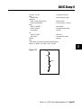
4+3. In fact, you may have the urge to put parentheses around portions of those equations to clear things up. Good!
Page 232 • BASIC Stamp Programming Manual 1.8 • Parallax, Inc.
BASIC Stamp II
The BS2 solves math problems in the order they are written—from left
to right. The result of each operation is fed into the next operation. So
to compute 12+3*2/4, the BS2 goes through a sequence like this:
12 + 3 = 5
5 * 2 = 10
10 / 4 = 2
the answer is 2
Note that because the BS2 performs integer math (whole numbers only)
that 10 / 4 results in 2, not 2.5. We’ll talk more about integers in the
next section.
Some other dialects of BASIC would compute that same expression
based on their precedence of operators, which requires that multiplication and division be done before addition. So the result would be:
3*2=6
6/4=1
12 + 1 = 13
the answer is 13
Once again, because of integer math, the fractional portion of 6 / 4 is
dropped, so we get 1 instead of 1.5.
Given the potential for misinterpretation, we must use parentheses to
make our mathematical intentions clear to the BS2 (not to mention
ourselves and other programmers who may look at our program). With
parentheses. Enclosing a math operation in parentheses gives it priority over other operations. For example, in the expression 1+(3*4), the
3*4 would be computed first, then added to 1.
To make the BS2 compute the previous expression in the conventional
BASIC way, you would write it as 12 + (3*2/4). Within the parentheses, the BS2 works from left to right. If you wanted to be even more
specific, you could write 12 + ((3*2)/4). When there are parentheses
within parentheses, the BS2 works from the innermost parentheses
outward. Parentheses placed within parentheses are said to be nested.
The BS2 lets you nest parentheses up to eight levels deep.
Parallax, Inc. • BASIC Stamp Programming Manual 1.8 • Page 233
2
BASIC Stamp II
Integer Math
The BS2 performs all math operations by the rules of positive integer
math. That is, it handles only whole numbers, and drops any fractional
portions from the results of computations. Although the BS2 can interpret two’s complement negative numbers correctly in Debug and Serout
instructions using modifiers like SDEC (for signed decimal), in calculations it assumes that all values are positive. This yields correct results with two’s complement negative numbers for addition, subtraction, and multiplication, but not for division.
This subject is a bit too large to cover here. If you understood the preceding paragraph, great. If you didn’t, but you understand that handling negative numbers requires a bit more planning (and probably
should be avoided when possible), good. And if you didn’t understand
the preceding paragraph at all, you might want to do some supplemental reading on computer-oriented math.
Unary and Binary Operators
In a previous section we discussed the operators you’re already familiar with: +, - ,* and /. These operators all work on two values, as in 1 +
3 or 26*144. The values that operators process are referred to as arguments. So we say that these operators take two arguments.
The minus sign (-) can also be used with a single argument, as in -4.
Now we can fight about whether that’s really shorthand for 0-4 and
therefore does have two arguments, or we can say that - has two roles:
as a subtraction operator that takes two arguments, and as a negation
operator that takes one. Operators that take one argument are called
unary operators and those that take two are called binary operators.
Please note that the term “binary operator” has nothing to do with
binary numbers—it’s just an inconvenient coincidence that the same
word, meaning ‘involving two things’ is used in both cases.
In classifying the BS2’s math and logic operators, we divide them into
two types: unary and binary. Remember the previous discussion of
operator precedence? Unary operators take precedence over binary—
the unary operation is always performed first. For example SQR is the
unary operator for square root. In the expression 10 - SQR 16, the BS2
first takes the square root of 16, then subtracts it from 10.
Page 234 • BASIC Stamp Programming Manual 1.8 • Parallax, Inc.
BASIC Stamp II
16-bit Workspace
Most of the descriptions that follow say something like ‘computes (some
function) of a 16-bit value.’ This does not mean that the operator does
not work on smaller byte or nibble values. It just means that the computation is done in a 16-bit workspace. If the value is smaller than 16
bits, the BS2 pads it with leading 0s to make a 16-bit value. If the 16-bit
result of a calculation is to be packed into a smaller variable, the higherorder bits are discarded (truncated).
Keep this in mind, especially when you are working with two’s complement negative numbers, or moving values from a larger variable to a
smaller one. For example, look what happens when you move a two’s
complement negative number into a byte:
b2 = -99
debug sdec ? b2
' Show signed decimal result (157).
How did -99 become 157? Let’s look at the bits: 99 is %01100011 binary.
When the BS2 negates 99, it converts the number to 16 bits
%0000000001100011, and then takes the two’s complement,
%1111111110011101. Since we’ve asked for the result to be placed in an
8-bit (byte) variable, the upper eight bits are truncated and the lower
eight bits stored in the byte: %10011101.
Now for the second half of the story. Debug’s SDEC modifier expects a
16-bit, two’s complement value, but has only a byte to work with. As
usual, it creates a 16-bit value by padding the leading eight bits with
0s: %0000000010011101. And what’s that in signed decimal? 157.
Each of the instruction descriptions below includes an example. It’s a
good idea to test your understanding of the operators by modifying
the examples and seeing whether you can predict the results. Experiment, learn, and work the Debug instruction until it screams for mercy!
The payoff will be a thorough understanding of both the BS2 and computer-oriented math.
Parallax, Inc. • BASIC Stamp Programming Manual 1.8 • Page 235
2
BASIC Stamp II
Unary (one-argument) Operators
Six Unary Operators are listed and explained below.
Table M-5. Unary Operators
Operator
Description
ABS
Returns absolute value
SQR
Returns square root of value
DCD
2n-power decoder
NCD
Priority encoder of a 16-bit value
SIN
Returns two’s compliment sine
COS
Returns two’s compliment cosine
ABS
Converts a signed (two’s complement) 16-bit number to its absolute
value. The absolute value of a number is a positive number representing the difference between that number and 0. For example, the absolute value of -99 is 99. The absolute value of 99 is also 99. ABS can be
said to strip off the minus sign from a negative number, leaving positive numbers unchanged.
ABS works on two’s complement negative numbers. Examples of ABS
at work:
w1 = -99
debug sdec ? w1
w1 = ABS w1
debug sdec ? w1
' Put -99 (two's complement format) into w1.
' Display it on the screen as a signed #.
' Now take its absolute value.
' Display it on the screen as a signed #.
SQR
Computes the integer square root of an unsigned 16-bit number. (The
number must be unsigned, when you think about it, because the square
root of a negative number is an ‘imaginary’ number.) Remember that
most square roots have a fractional part that the BS2 discards in doing
its integer-only math. So it computes the square root of 100 as 10 (correct), but the square root of 99 as 9 (the actual is close to 9.95). Example:
Page 236 • BASIC Stamp Programming Manual 1.8 • Parallax, Inc.
BASIC Stamp II
debug SQR 100
debug SQR 99
' Display square root of 100 (10).
' Display of square root of 99 (9 due to truncation)
DCD
2n-power decoder of a four-bit value. DCD accepts a value from 0 to
15, and returns a 16-bit number with that bit number set to 1. For example:
w1 = DCD 12
debug bin ? w1
' Set bit 12.
' Display result (%0001000000000000)
NCD
Priority encoder of a 16-bit value. NCD takes a 16-bit value, finds the
highest bit containing a 1 and returns the bit position plus one (1 through
16). If no bit is set—the input value is 0—NCD returns 0. NCD is a fast
way to get an answer to the question “what is the largest power of two
that this value is greater than or equal to?” The answer that NCD returns will be that power, plus one. Example:
w1 = %1101
debug ? NCD w1
' Highest bit set is bit 3.
' Show the NCD of w1 (4).
Negates a 16-bit number (converts to its two’s complement).
w1 = -99
debug sdec ? w1
w1 = ABS w1
debug sdec ? w1
' Put -99 (two's complement format) into w1.
' Display it on the screen as a signed #.
' Now take its absolute value.
' Display it on the screen as a signed #.
~
Complements (inverts) the bits of a number. Each bit that contains a 1
is changed to 0 and each bit containing 0 is changed to 1. This process
is also known as a “bitwise NOT.” For example:
b1 = %11110001
debug bin ? b1
b1 = ~ b1
debug bin ? b1
' Store bits in byte b1.
' Display in binary (%11110001).
' Complement b1.
' Display in binary (%00001110).
Parallax, Inc. • BASIC Stamp Programming Manual 1.8 • Page 237
2
BASIC Stamp II
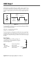
SIN
Returns the two’s complement, 8-bit sine of an angle specified as an 8bit (0 to 255) angle. To understand the BS2 SIN operator more completely, let’s look at a typical sine function. By definition: given a circle
with a radius of 1 unit (known as a unit circle), the sine is the y-coordinate distance from the center of the circle to its edge at a given angle.
Angles are measured relative to the 3-o'clock position on the circle,
increasing as you go around the circle counterclockwise.
At the origin point (0 degrees) the sine is 0, because that point has the
same y (vertical) coordinate as the circle center; at 45 degrees, sine is
0.707; at 90 degrees, 1; 180 degrees, 0 again; 270 degrees, -1.
The BS2 SIN operator breaks the circle into 0 to 255 units instead of 0 to
359 degrees. Some textbooks call this unit a binary radian or brad. Each
brad is equivalent to 1.406 degrees. And instead of a unit circle, which
results in fractional sine values between 0 and 1, BS2 SIN is based on a
127-unit circle. Results are given in two’s complement in order to accommodate negative values. So, at the origin, SIN is 0; at 45 degrees
(32 brads), 90; 90 degrees (64 brads), 127; 180 degrees (128 brads), 0;
270 degrees (192 brads), -127.
To convert brads to degrees, multiply by 180 then divide by 128; to
convert degrees to brads, multiply by 128, then divide by 180. Here’s a
small program that demonstrates the SIN operator:
degr
var
w1
sine
var
w2
for degr = 0 to 359 step 45
sine = SIN (degr * 128 / 180)
debug "Angle: ",DEC degr,tab,"Sine: ",SDEC sine,cr
next
' Define variables.
' Use degrees.
' Convert to brads, do SIN.
' Display.
COS
Returns the two’s complement, 8-bit cosine of an angle specified as an
8-bit (0 to 255) angle. See the explanation of the SIN operator above.
COS is the same in all respects, except that the cosine function returns
the x distance instead of the y distance. To demonstrate the COS operator, use the example program from SIN above, but substitute COS
for SIN.
Page 238 • BASIC Stamp Programming Manual 1.8 • Parallax, Inc.
BASIC Stamp II
Binary (two-argument) Operators
Sixteen Binary Operators are listed and explaned below.
Table M-6. Binary Operators
Operator
Description
+
Addition
-
Subtraction
/
Division
//
Remainder of division
*
Multiplication
**
High 16-bits of multiplication
*/
Multiply by 8-bit whole and 8-bit part
MIN
Limits a value to specified low
MAX
Limits a value to specified high
DIG
Returns specified digit of number
<<
Shift bits left by specified amount
>>
Shift bits right by specified amount
REV
Reverse specified number of bits
&
Bitwise AND of two values
|
Bitwise OR of two values
^
Bitwise XOR of two values
+
Adds variables and/or constants, returning a 16-bit result. Works exactly as you would expect with unsigned integers from 0 to 65535. If
the result of addition is larger than 65535, the carry bit will be lost. If
the values added are signed 16-bit numbers and the destination is a
16-bit variable, the result of the addition will be correct in both sign
and value. For example, the expression -1575 + 976 will result in the
signed value -599. See for yourself:
Parallax, Inc. • BASIC Stamp Programming Manual 1.8 • Page 239
2
BASIC Stamp II
w1 = -1575
w2 = 976
w1 = w1 + w2
debug sdec ? w1
' Add the numbers.
' Show the result (-599).
Subtracts variables and/or constants, returning a 16-bit result. Works
exactly as you would expect with unsigned integers from 0 to 65535. If
the result is negative, it will be correctly expressed as a signed 16-bit
number. For example:
w1 = 1000
w2 = 1999
w1 = w1 - w2
debug sdec ? w1
' Subtract the numbers.
' Show the result (-999).
/
Divides variables and/or constants, returning a 16-bit result. Works
exactly as you would expect with unsigned integers from 0 to 65535.
Use / only with positive values; signed values do not provide correct
results. Here’s an example of unsigned division:
w1 = 1000
w2 = 5
w1 = w1 / w2
debug dec ? w1
' Divide w1 by w2.
' Show the result (200).
A workaround to the inability to divide signed numbers is to have
your program divide absolute values, then negate the result if one (and
only one) of the operands was negative. All values must lie within the
range of -32767 to +32767. Here is an example:
sign
w1 = 100
w2 = -3200
var
sign = w1.bit15 ^ w2.bit15
w2 = abs w2 / abs w1
if sign = 0 then skip0
w2 = -w2
skip0:
debug sdec ? w2
bit
' Bit to hold the sign.
' Sign = (w1 sign) XOR (w2 sign).
' Divide absolute values.
' Negate result if one of the
' arguments was negative.
' Show the result (-32)
Page 240 • BASIC Stamp Programming Manual 1.8 • Parallax, Inc.
BASIC Stamp II
//
Returns the remainder left after dividing one value by another. Some
division problems don’t have a whole-number result; they return a
whole number and a fraction. For example, 1000/6 = 166.667. Integer
math doesn’t allow the fractional portion of the result, so 1000/6 = 166.
However, 166 is an approximate answer, because 166*6 = 996. The division operation left a remainder of 4. The // (double-slash) returns
the remainder of a given division operation. Naturally, numbers that
divide evenly, such as 1000/5, produce a remainder of 0. Example:
w1 = 1000
w2 = 6
w1 = w1 // w2
debug dec ? w1
' Get remainder of w1 / w2.
' Show the result (4).
*
Multiplies variables and/or constants, returning the low 16 bits of the
result. Works exactly as you would expect with unsigned integers from
0 to 65535. If the result of multiplication is larger than 65535, the excess
bits will be lost. Multiplication of signed variables will be correct in
both number and sign, provided that the result is in the range -32767
to +32767.
w1 = 1000
w2 = -19
w1 = w1 * w2
debug sdec ? w1
' Multiply w1 by w2.
' Show the result (-19000).
**
Multiplies variables and/or constants, returning the high 16 bits of the
result. When you multiply two 16-bit values, the result can be as large
as 32 bits. Since the largest variable supported by PBASIC2 is 16 bits,
the highest 16 bits of a 32-bit multiplication result are normally lost.
The ** (double-star) instruction gives you these upper 16 bits. For
example, suppose you multiply 65000 ($FDE8) by itself. The result is
4,225,000,000 or $FBD46240. The * (star, or normal multiplication)
-instruction would return the lower 16 bits, $6240. The ** instruction
returns $FBD4.
Parallax, Inc. • BASIC Stamp Programming Manual 1.8 • Page 241
2
BASIC Stamp II
w1 = $FDE8
w2 = w1 ** w1
debug hex ? w2
' Multiply $FDE8 by itself
' Return high 16 bits.
*/
Multiplies variables and/or constants, returning the middle 16 bits of
the 32-bit result. This has the effect of multiplying a value by a whole
number and a fraction. The whole number is the upper byte of the
multiplier (0 to 255 whole units) and the fraction is the lower byte of
the multiplier (0 to 255 units of 1/256 each). The */ (star-slash) instruction gives you an excellent workaround for the BS2’s integer-only math.
Suppose you want to multiply a value by 1.5. The whole number, and
therefore the upper byte of the multiplier, would be 1, and the lower
byte (fractional part) would be 128, since 128/256 = 0.5. It may be clearer
to express the */ multiplier in hex—as $0180—since hex keeps the contents of the upper and lower bytes separate. An example:
w1 = 100
w1 = w1 */ $0180
debug ? w1
' Multiply by 1.5 [1 + (128/256)]
' Show result (150).
To calculate constants for use with the */ instruction, put the whole
number portion in the upper byte, then multiply the fractional part by
256 and put that in the lower byte. For instance, take Pi (π, 3.14159).
The upper byte would be $03 (the whole number), and the lower would
be 0.14159 * 256 = 36 ($24). So the constant Pi for use with */ would be
$0324. This isn’t a perfect match for Pi, but the error is only about 0.1%.
MIN
Limits a value to a specified 16-bit positive minimum. The syntax of
MIN is:
value MIN limit
Where:
• value is value to perform the MIN function upon.
• limit is the minimum value that value is allowed to be.
Page 242 • BASIC Stamp Programming Manual 1.8 • Parallax, Inc.
BASIC Stamp II
Its logic is, ‘if value is less than limit, then make value = limit; if value
is greater than or equal to limit, leave value alone.’ MIN works in positive math only; its comparisons are not valid when used on two’s
complement negative numbers, since the positive-integer representation of a number like -1 ($FFFF or 65535 in unsigned decimal) is larger
than that of a number like 10 ($000A or 10 decimal). Use MIN only
with unsigned integers. Because of the way fixed-size integers work,
you should be careful when using an expression involving MIN 0. For
example, 0-1 MIN 0 will result in 65535 because of the way fixed-size
integers wrap around.
for w1 = 100 to 0 step -10
debug ? w1 MIN 50
next
' Walk value of w1 from 100 to 0.
' Show w1, but use MIN to clamp at 50.
MAX
2
Limits a value to a specified 16-bit positive maximum. The syntax of
MAX is:
value MAX limit
Where:
• value is value to perform the MAX function upon.
• limit is the maximum value that value is allowed to be.
Its logic is, ‘if value is greater than limit, then make value = limit; if
value is less than or equal to limit, leave value alone.’ MAX works in
positive math only; its comparisons are not valid when used on two’s
complement negative numbers, since the positive-integer representation of a number like -1 ($FFFF or 65535 in unsigned decimal) is larger
than that of a number like 10 ($000A or 10 decimal). Use MAX only
with unsigned integers. Also be careful of expressions involving MAX
65535. For example 65535 + 1 MAX 65535 will result in 0 because of the
way fixed-size integers wrap around.
for w1 = 0 to 100 step 10
debug ? w1 MAX 50
next
' Walk value of w1 from 0 to 100.
' Show w1, but use MAX to clamp at 50.
Parallax, Inc. • BASIC Stamp Programming Manual 1.8 • Page 243
BASIC Stamp II
DIG
Returns the specified decimal digit of a 16-bit positive value. Digits are
numbered from 0 (the rightmost digit) to 4 (the leftmost digit of a 16bit number; 0 to 65535). Example:
w1 = 9742
debug ? w1 DIG 2
for b0 = 0 to 4
debug ? w1 DIG b0
next
' Show digit 2 (7)
' Show digits 0 through 4 of 9742.
<<
Shifts the bits of a value to the left a specified number of places. Bits
shifted off the left end of a number are lost; bits shifted into the right
end of the number are 0s. Shifting the bits of a value left n number of
times also has the effect of multiplying that number by two to the nth
power. For instance 100 << 3 (shift the bits of the decimal number 100
left three places) is equivalent to 100 * 23. Example:
w1 = %1111111111111111
for b0 = 1 to 16
debug BIN ? w1 << b0
next
' Repeat with b0 = 1 to 16.
' Shift w1 left b0 places.
>>
Shifts the bits of a variable to the right a specified number of places.
Bits shifted off the right end of a number are lost; bits shifted into the
left end of the number are 0s. Shifting the bits of a value right n
number of times also has the effect of dividing that number by two to
the nth power. For instance 100 >> 3 (shift the bits of the decimal
number 100 right three places) is equivalent to 100 / 23. Example:
w1 = %1111111111111111
for b0 = 1 to 16
debug BIN ? w1 >> b0
next
' Repeat with b0 = 1 to 16.
' Shift w1 right b0 places.
Page 244 • BASIC Stamp Programming Manual 1.8 • Parallax, Inc.
BASIC Stamp II
REV
Returns a reversed (mirrored) copy of a specified number of bits of a
value, starting with the rightmost bit (lsb). For instance, %10101101
REV 4 would return %1011, a mirror image of the first four bits of the
value. Example:
debug bin ? %11001011 REV 4
' Mirror 1st 4 bits (%1101)
&
Returns the bitwise AND of two values. Each bit of the values is subject to the following logic:
0 AND 0 = 0
0 AND 1 = 0
1 AND 0 = 0
1 AND 1 = 1
2
The result returned by & will contain 1s in only those bit positions in
which both input values contain 1s. Example:
debug bin ? %00001111 & %10101101
' Show AND result (%00001101)
|
Returns the bitwise OR of two values. Each bit of the values is subject
to the following logic:
0 OR 0 = 0
0 OR 1 = 1
1 OR 0 = 1
1 OR 1 = 1
The result returned by | will contain 1s in any bit positions in which
one or the other or both input values contain 1s. Example:
debug bin ? %00001111 | %10101001
' Show OR result (%10101111)
Parallax, Inc. • BASIC Stamp Programming Manual 1.8 • Page 245
BASIC Stamp II
^
Returns the bitwise XOR of two values. Each bit of the values is subject
to the following logic:
0 XOR 0 = 0
0 XOR 1 = 1
1 XOR 0 = 1
1 XOR 1 = 0
The result returned by ^ will contain 1s in any bit positions in which
one or the other (but not both) input values contain 1s. Example:
debug bin ? %00001111 ^ %10101001
' Show XOR result (%10100110)
Page 246 • BASIC Stamp Programming Manual 1.8 • Parallax, Inc.
BASIC Stamp II
Branch
BRANCH offset, [address0, address1, ...addressN]
Go to the address specified by offset (if in range).
• Offset is a variable/constant that specifies which of the listed
address to go to (0—N).
• Addresses are labels that specify where to go.
Explanation
Branch is useful when you might want to write something like this:
if b2 = 0 then case_0
if b2 = 1 then case_1
if b2 = 2 then case_2
' b2=0: go to label "case_0"
' b2=1: go to label "case_1"
' b2=2: go to label "case_2"
You can use Branch to organize this logic into a single statement:
2
BRANCH b2,[case_0,case_1,case_2]
This works exactly the same as the previous If...Then example. If the
value isn’t in range—in this case, if b2 is greater than 2—Branch does
nothing and the program continues execution on the next instruction
after Branch.
Demo Program
This program shows how the value of the variable pick controls the
destination of the Branch instruction.
pick
Branch.
var
nib
' Variable to pick destination of
for pick = 0 to 3
' Repeat with pick= 0,1,2,3.
debug "Pick= ", DEC pick, cr
' Show value of pick.
BRANCH pick,[zero,one,two]
' Branch based on pick.
debug "Pick exceeded # of items",cr,"in BRANCH list. Fell through!",cr
nextPick:
next
' Next value of pick.
stop
zero:
debug "Branched to 'zero.'",cr,cr
goto nextPick
one:
debug "Branched to 'one.'",cr,cr
Parallax, Inc. • BASIC Stamp Programming Manual 1.8 • Page 247
BASIC Stamp II
goto nextPick
two:
debug "Branched to 'two.'",cr,cr
goto nextPick
Page 248 • BASIC Stamp Programming Manual 1.8 • Parallax, Inc.
BASIC Stamp II
Button
BUTTON pin, downstate, delay, rate, bytevariable, targetstate, address
Debounce button input, perform auto-repeat, and branch to address if
button is in target state. Button circuits may be active-low or activehigh.
• Pin is a variable/constant (0–15) that specifies the I/O pin to use.
This pin will be made an input.
• Downstate is a variable/constant (0 or 1) that specifies which
logical state occurs when the button is pressed.
• Delay is a variable/constant (0–255) that specifies how long the
button must be pressed before auto-repeat starts. The delay is
measured in cycles of the Button routine. Delay has two special
settings: 0 and 255. If Delay is 0, Button performs no debounce or
auto-repeat. If Delay is 255, Button performs debounce, but no
auto-repeat.
• Rate is a variable/constant (0–255) that specifies the number of
cycles between autorepeats. The rate is expressed in cycles of the
Button routine.
• Bytevariable is the workspace for Button. It must be cleared to 0
before being used by Button for the first time.
• Targetstate is a variable/constant (0 or 1) that specifies which
state the button should be in for a branch to occur. (0=not pressed,
1=pressed)
• Address is a label that specifies where to branch if the button is
in the target state.
Explanation
When you press a button or flip a switch, the contacts make or break a
connection. A brief (1 to 20-ms) burst of noise occurs as the contacts
scrape and bounce against each other. Button’s debounce feature
prevents this noise from being interpreted as more than one switch
action. (For a demonstration of switch bounce, see the demo program
for the Count instruction.)
Button also lets PBASIC react to a button press the way your computer
keyboard does to a key press. When you press a key, a character
Parallax, Inc. • BASIC Stamp Programming Manual 1.8 • Page 249
2
BASIC Stamp II
immediately appears on the screen. If you hold the key down, there’s a
delay, then a rapid-fire stream of characters appears on the screen.
Button’s auto-repeat function can be set up to work much the same way.
Button is designed to be used inside a program loop. Each time through
the loop, Button checks the state of the specified pin. When it first
matches downstate, Button debounces the switch. Then, in accordance
with targetstate, it either branches to address (targetstate = 1) or doesn’t
(targetstate = 0).
If the switch stays in downstate, Button counts the number of program
loops that execute. When this count equals delay, Button once again
triggers the action specified by targetstate and address. Hereafter, if the
switch remains in downstate, Button waits rate number of cycles between
actions.
Button does not stop program execution. In order for its delay and
autorepeat functions to work properly, Button must be executed from
within a program loop.
Demo Program
Connect the active-low circuit shown in figure I-1 to pin P7 of the BS2.
When you press the button, the Debug screen will display an asterisk
(*). Feel free to modify the program to see the effects of your changes on
the way Button responds.
btnWk
var
byte
' Workspace for BUTTON instruction.
btnWk = 0
' Clear the workspace variable.
' Try changing the Delay value (255) in BUTTON to see the effect of
' its modes: 0=no debounce; 1-254=varying delays before autorepeat;
' 255=no autorepeat (one action per button press).
Loop:
BUTTON 7,0,255,250,btnWk,0,noPress
' Go to noPress UNLESS..
debug "* "
' ..P7 is 0.
noPress: goto loop
' Repeat endlessly.
Figure I-1
+5V
+5V
10k
to I/O pin
to I/O pin
10k
active-high
(downstate = 1)
active-low
(downstate = 0)
Page 250 • BASIC Stamp Programming Manual 1.8 • Parallax, Inc.
BASIC Stamp II
Count
COUNT pin, period, variable
Count the number of cycles (0-1-0 or 1-0-1) on the specified pin during
period number of milliseconds and store that number in variable.
• Pin is a variable/constant (0–15) that specifies the I/O pin to use.
This pin will be placed into input mode by writing a 0 to the
corresponding bit of the DIRS register.
• Period is a variable/constant (1 to 65535) specifying the time in
milliseconds during which to count.
• Variable is a variable (usually a word) in which the count will be
stored.
Explanation
The Count instruction makes a pin an input, then for the specified
number of milliseconds counts cycles on that pin and stores the total in
a variable. A cycle is a change in state from 1 to 0 to 1, or from 0 to 1 to 0.
Count can respond to transitions as fast as 4 microseconds (µs). A cycle
consists of two transitions (e.g., 0 to 1, then 1 to 0), so Count can respond
to square waves with periods as short as 8 µs; up to 125 kilohertz (kHz)
in frequency. For non-square waves (those whose high time and low
time are unequal), the shorter of the high and low times must be greater
than 4 µs.
If you use Count on slowly-changing analog waveforms like sine
waves, you may find that the count value returned is higher than
expected. This is because the waveform may pass through the BS2’s 1.5volt logic threshold slowly enough that noise causes false counts. You
can fix this by passing the signal through a Schmitt trigger, like one of
the inverters of a 74HCT14.
Demo Program
Connect the active-low circuit shown in figure I-1 (Button instruction)
to pin P7 of the BS2. The Debug screen will prompt you to press the
button as quickly as possible for a 1-second count. When the count is
done, the screen will display your “score,” the total number of cycles
registered by count. Note that this score will almost always be greater
than the actual number of presses because of switch bounce.
Parallax, Inc. • BASIC Stamp Programming Manual 1.8 • Page 251
2
BASIC Stamp II
cycles
var
word
' Variable to store counted cycles.
loop:
debug cls,"How many times can you press the button in 1 second?",cr
pause 1000: debug "Ready, set... ":pause 500:debug "GO!",cr
count 7,1000,cycles
debug cr,"Your score: ", DEC cycles,cr
pause 3000
debug "Press button to go again."
hold: if IN7 = 1 then hold
goto loop
Page 252 • BASIC Stamp Programming Manual 1.8 • Parallax, Inc.
BASIC Stamp II
Debug
DEBUG outputData{,outputData...}
Display variables and messages on the PC screen within the STAMP2
host program.
• OutputData consists of one or more of the following: text strings,
variables, constants, expressions, formatting modifiers, and
control characters
Explanation
Debug provides a convenient way for your programs to send messages
to the PC screen during programming. The name Debug suggests its
most popular use—debugging programs by showing you the value of
a variable or expression, or by indicating what portion of a program is
currently executing. Debug is also a great way to rehearse programming techniques. Throughout this instruction guide, we use Debug to
give you immediate feedback on the effects of instructions. Let’s look at
some examples:
DEBUG "Hello World!"
' Test message.
After you press ALT-R to download this one-line program to the BS2,
the STAMP2 host software will put a Debug window on your PC screen
and wait for a response. A moment later, the phrase "Hello World!" will
appear. Pressing any key other than space eliminates the Debug window. Your program keeps executing after the screen is gone, but you
can’t see the Debug data. Another example:
x
var
DEBUG dec x
byte: x = 65
' Show decimal value of x.
Since x = 65, the Debug window would display “65.” In addition to
decimal, Debug can display values in hexidecimal and binary. See table
I-1 for a complete list of Debug prefixes.
Suppose that your program contained several Debug instructions
showing the contents of different variables. You would want some way
to tell them apart. Just add a question mark (?) as follows:
x
var
DEBUG dec ? x
byte: x = 65
' Show decimal value of x with label "x = "
Now Debug displays “x = 65.” Debug works with expressions, too:
Parallax, Inc. • BASIC Stamp Programming Manual 1.8 • Page 253
2
BASIC Stamp II
x
var
DEBUG dec ? 2*(x-1)
byte: x = 65
' Show decimal result with "2*(x-1) = "
The Debug window would display "2*(x-1) = 128." If you omit the ?, the
display would be just “128.” If you tell Debug to display a value without
formatting it as a number, you get the ASCII character equivalent of the
value:
x var byte: x = 65
DEBUG x
' Show x as ASCII.
Since x = 65, and 65 is the ASCII character code for the letter A (see
appendix), the Debug window would show A. Up to now, we’ve shown
Debug with just one argument, but you can display additional items by
adding them to the Debug list, separated by commas:
x
var
byte: x = 65
DEBUG "The ASCII code for A is: ", dec x
' Show phrase, x.
Since individual Debug instructions can grow to be fairly complicated,
and since a program can contain many Debugs, you’ll probably want to
control the formatting of the Debug screen. Debug supports six formatting characters:
Symbol
CLS 0
HOME
BELL
BKSP
TAB 9
CR 13
Value Effect
clear Debug screen
1
home cursor to top left corner of screen
7
beep the PC speaker
8
back up one space
tab to the next multiple-of-8 text column
carriage return to the beginning of the next line
Try the example below with and without the CR at the end of the first
Debug:
Debug "A carriage return",CR
Debug "starts a new line"
Technical Background
Debug is actually a special case of the Serout instruction. It is set for
inverted (RS-232-compatible) serial output through the BS2 programming connector (SOUT on the BS2-IC) at 9600 baud, no parity, 8 data
bits, and 1 stop bit. You may view Debug output using a terminal
program set to these parameters, but you must modify either your
Page 254 • BASIC Stamp Programming Manual 1.8 • Parallax, Inc.
BASIC Stamp II
carrier board or the serial cable to temporarily disconnect pin 3 of the
BS2-IC (pin 4 of the DB-9 connector). The reason is that the STAMP2
host software uses this line to reset the BS2 for programming, while
terminal software uses the same line to signal “ready” for serial communication.
If you make this modification, be sure to provide a way to reconnect pin
3 of the BS2-IC to pin 4 of the DB-9 connector for reprogramming. With
these pins disconnected, the STAMP2 host software will not be able to
download new programs.
Demo Program
This demo shows the letters of the alphabet and their corresponding
ASCII codes. A brief pause slows the process down a little so that it
doesn’t go by in a blur. You can freeze the display while the program is
running by pressing the space bar.
letter
var
byte
Debug "ALPHABET -> ASCII CHART",BELL,CR,CR
for letter = "A" to "Z"
Debug "Character: ", letter, tab, "ASCII code: ",dec letter, cr
pause 200
next
Parallax, Inc. • BASIC Stamp Programming Manual 1.8 • Page 255
2
BASIC Stamp II
Table I-1. Debug Modifiers
Modifier
ASC?
DEC {1..5}
SDEC {1..5}
HEX {1..4}
SHEX {1..4}
IHEX {1..4}
ISHEX {1..4}
BIN {1..16}
SBIN {1..16}
IBIN {1..16}
ISBIN {1..16}
STR bytearray
STR bytearray\n
REP byte\n
Effect
Displays "variablename = 'character'" + carriage
return; where character is an ASCII character.
Decimal text, optionally fixed for 1 to 5 digits
Signed decimal text, optionally fixed for 1 to 5 digits
Hexadecimal text, optionally fixed for 1 to 4 digits
Signed hex text, optionally fixed for 1 to 4 digits
Indicated hex text ($ prefix; e.g., $7A3), optionally
fixed for 1 to 4 digits
Indicated signed hex text, optionally fixed for 1 to
4 digits
Binary text, optionally fixed for 1 to 16 digits
Signed binary text, optionally fixed for 1 to 16 digits
Indicated binary text (% prefix; e.g., %10101100),
optionally fixed for 1 to 16 digits
Indicated signed binary text, optionally fixed for 1 to
16 digits
Display an ASCII string from bytearray until byte = 0.
Display an ASCII string consisting of n bytes from
bytearray.
Display an ASCII string consisting of byte repeated n
times (e.g., REP "X"\10 sends XXXXXXXXXX).
Notes
1
1, 2
1
1, 2
1
1, 2
1
1, 2
1, 2
1, 2
NOTES:
(1) Fixed-digit modifiers like DEC4 will pad text with leading 0s if necessary; e.g.,
DEC4 65 sends 0065. If a number is larger than the specified number of digits, the
leading digits will be dropped; e.g., DEC4 56422 sends 6422.
(2) Signed modifiers work under two’s complement rules, same as PBASIC2 math.
Value must be no less than a word variable in size.
Page 256 • BASIC Stamp Programming Manual 1.8 • Parallax, Inc.
BASIC Stamp II
DTMFout
DTMFOUT pin,{ontime,offtime,}{,tone...}
Generate dual-tone, multifrequency tones (DTMF, i.e., telephone “touch”
tones).
• Pin is a variable/constant (0–15) that specifies the I/O pin to use.
This pin will be put into output mode temporarily during generation of
tones. After tone generation is complete, the pin is left in input mode,
even if it was previously an output.
• Ontime is an optional entry; a variable or constant (0 to 65535)
specifying a duration of the tone in milliseconds. If ontime is not
specified, DTMFout defaults to 200 ms on.
• Offtime is an optional entry; a variable or constant (0 to 65535)
specifying the length of silent pause after a tone (or between
tones, if multiple tones are specified). If offtime is not specified,
DTMFout defaults to 50 ms off.
• Tone is a variable or constant (0—15) specifying the DTMF tone
to send. Tones 0 through 11 correspond to the standard layout of
the telephone keypad, while 12 through 15 are the fourth-column
tones used by phone test equipment and in ham-radio applications.
0—9
10
11
12—15
Digits 0 through 9
Star (*)
Pound (#)
Fourth column tones A through D
Explanation
DTMF tones are used to dial the phone or remotely control certain radio
equipment. The BS2 can generate these tones digitally using the
DTMFout instruction. Figure I-2 shows how to connect a speaker or
audio amplifier to hear these tones; figure I-3 shows how to connect the
BS2 to the phone line. A typical DTMFout instruction to dial a phone
through pin 0 with the interface circuit of figure I-3 would look like this:
DTMFOUT 0,[6,2,4,8,3,3,3]' Call Parallax.
That instruction would be equivalent to dialing 624-8333 from a phone
keypad. If you wanted to slow the pace of the dialing to accommodate
Parallax, Inc. • BASIC Stamp Programming Manual 1.8 • Page 257
2
BASIC Stamp II
a noisy phone line or radio link, you could use the optional ontime and
offtime values:
DTMFOUT 0,500,100,[6,2,4,8,3,3,3]
' Call Parallax, slowly.
In that instruction, ontime is set to 500 ms (1/2 second) and offtime to
100 ms (1/10th second).
Technical Background
The BS2’s controller is a purely digital device. DTMF tones are analog
waveforms, consisting of a mixture of two sine waves at different audio
frequencies. So how does a digital device generate analog output? The
BS2 creates and mixes the sine waves mathematically, then uses the
resulting stream of numbers to control the duty cycle of a very fast
pulse-width modulation (PWM) routine. So what’s actually coming out
of the BS2 pin is a rapid stream of pulses. The purpose of the filtering
arrangements shown in the schematics of figures I-2 and I-3 is to smooth
out the high-frequency PWM, leaving only the lower frequency audio
behind.
Keep this in mind if you want to interface BS2 DTMF output to radios
and other equipment that could be adversely affected by the presence
of high-frequency noise on the input. Make sure to filter the DTMF
output thoroughly. The circuits shown here are only a starting point;
you may want to use an active low-pass filter with a roll-off point
around 2 kHz.
Demo Program
This demo program is a rudimentary memory dialer. Since DTMF
Figure I-2
Driving an Audio Amplifier
1k
1k
I/O pin
0.1µF
0.01µF
Amplifier
(e.g., Radio Shack
277-1008C)
Driving a Speaker
10µF (both)
I/O pin
+
C1
+
C2
≥40Ω Speaker
(or 8Ω in series
with 33Ω resistor)
Notes:
C1 may be omitted for piezo speakers
C2 is optional, but reduces high-frequency noise
Page 258 • BASIC Stamp Programming Manual 1.8 • Parallax, Inc.
BASIC Stamp II
Figure I-3
Interfacing to the Telephone Line
connect switch (or
relay contacts)
phone line
(red and green)
600-600Ω
transformer
(JC: 117760)
10Ω
(both)
270V “Sidactor”
(DK: P3000AA61-ND)
1k
0.1µF
I/O pin
0.001µF
3.9V zeners (both)
DK: 1N5228BCT-ND
Parts Sources
Digi-Key (DK), 1-800-344-4539
or 218-681-6674
Jameco (JC), 1-800-831-4242
or 415-592-8097
digits fit within a nibble (four bits), the program below packs two DTMF
digits into each byte of three EEPROM data tables. The end of a phone
number is marked by the nibble $F, since this is not a valid phonedialing digit.
EEloc
EEbyte
DTdigit
phone
hiLo
var
var
var
var
var
byte
byte
EEbyte.highnib
nib
bit
Scott
Chip
Info
data
data
data
$45,$94,$80,$2F
' Phone: 459-4802
$19,$16,$62,$48,$33,$3F ' Phone: 1-916-624-8333
$15,$20,$55,$51,$21,$2F ' Phone: 1-520-555-1212
for phone = 0 to 2
lookup phone,[Scott,Chip,Info],EEloc
dial:
read EEloc,EEbyte
for hiLo = 0 to 1
if DTdigit = $F then done
DTMFout 0,[DTdigit]
EEbyte = EEbyte << 4
next
EEloc = EEloc+1
goto dial
done:
pause 2000
Wait a couple of seconds.
next
stop
' EEPROM address of stored number.
' Byte containing two DTMF digits.
' Digit to dial.
' Pick a phone #.
' Bit to select upper and lower nibble.
' Dial each phone #.
' Get location of # in EEPROM.
' Retrieve byte from EEPROM.
' Dial upper and lower digits.
' Hex $F is end-of-number flag
' Dial digit.
' Shift in next digit.
' Next pair of digits.
' Keep dialing until done ($F in DTdigit).
' This number is done.
'
' Dial next phone number.
Parallax, Inc. • BASIC Stamp Programming Manual 1.8 • Page 259
2
BASIC Stamp II
End
END
End the program, placing the BS2 in a low-power mode.
Explanation
End puts the BS2 into its inactive, low-power mode. In this mode the
BS2’s current draw (exclusive of loads driven by the I/O pins) is
approximately 50µA.
End keeps the BS2 inactive until the reset button is pushed or the power
is cycled off and back on.
Just as during Sleep intervals, pins will retain their input or output
settings after the BS2 is deactivated by End. So if a pin is driving a load
when End occurs, it will continue to drive that load after End. However,
at approximate 2.3-second intervals, output pins will disconnect (go
into input mode) for a period of approximately 18 ms. Then they will
revert to their former states.
For example, if the BS2 is driving an LED on when End executes, the
LED will stay lit after end. But every 2.3 seconds, there will be a visible
wink of the LED as the output pin driving it disconnects for 18 ms.
Page 260 • BASIC Stamp Programming Manual 1.8 • Parallax, Inc.
BASIC Stamp II
For...Next
FOR variable = start to end {STEP stepVal} ... NEXT
Create a repeating loop that executes the program lines between For
and Next, incrementing or decrementing variable according to stepVal
until the value of the variable passes the end value.
• Variable is a bit, nib, byte or word variable used as a counter.
• Start is a variable or constant that specifies the initial value of the
variable.
• End is a variable or constant that specifies the end value of the
variable. When the value of the variable passes end, the For...Next
loop stops executing and the program goes on to the instruction
after Next.
• StepVal is an optional variable or constant by which the variable
increases or decreases with each trip through the For/Next loop.
If start is larger than end, PBASIC2 understands stepVal to be
negative, even though no minus sign is used.
Explanation
For...Next loops let your program execute a series of instructions for a
specified number of repetitions. In simplest form:
reps var nib
FOR reps = 1 to 3
debug "*"
NEXT
' Counter for the FOR/NEXT loop.
' Repeat with reps = 1, 2, 3.
' Each rep, put one * on the screen.
Each time the For...Next loop above executes, the value of reps is
updated. See for yourself:
reps var nib
FOR reps = 1 to 10
debug dec ? reps
NEXT
' Counter for the FOR/NEXT loop.
' Repeat with reps = 1, 2... 10.
' Each rep, show values of reps.
For...Next can also handle cases in which the start value is greater than
the end value. It makes the commonsense assumption that you want to
count down from start to end, like so:
reps var nib
FOR reps = 10 to 1
debug dec ? reps
NEXT
' Counter for the FOR/NEXT loop.
' Repeat with reps = 10, 9...1.
' Each rep, show values of reps.
Parallax, Inc. • BASIC Stamp Programming Manual 1.8 • Page 261
2
BASIC Stamp II
If you want For...Next to count by some amount other than 1, you can
specify a stepVal. For example, change the previous example to count
down by 3:
reps var nib
FOR reps = 10 to 1 STEP 3
debug dec ? reps
NEXT
' Counter for the FOR/NEXT loop.
' Repeat with reps = 10, 7...1.
' Each rep, show values of reps.
Note that even though you are counting down, stepVal is still positive.
For...Next takes its cue from the relationship between start and end, not
the sign of stepVal. In fact, although PBASIC2 won’t squawk if you use
a negative entry for stepVal, its positive-integer math treats these values
as large positive numbers. For example, –1 in two’s complement is
65535. So the following code executes only once:
reps var word
FOR reps = 1 to 10 STEP -1
debug dec ? reps
NEXT
' Counter for the FOR/NEXT loop.
' Actually FOR reps = 1 to 10 step 65535
' Executes only once.
This brings up a good point: the instructions inside a For...Next loop
always execute once, no matter what start, end and stepVal values are
assigned.
There is a potential bug that you should be careful to avoid. PBASIC
uses unsigned 16-bit integer math to increment/decrement the counter
variable and compare it to the stop value. The maximum value a 16-bit
variable can hold is 65535. If you add 1 to 65535, you get 0 as the 16-bit
register rolls over (like a car’s odometer does when you exceed the
maximum mileage it can display).
If you write a For...Next loop whose step value is larger than the
difference between the stop value and 65535, this rollover will cause the
loop to execute more times than you expect. Try the following example:
reps var word
FOR reps = 0 to 65500 STEP 3000
debug dec ? reps
NEXT
' Counter for the loop.
' Each loop add 3000.
' Show reps in debug window.
' Again until reps>65500.
The value of reps increases by 3000 each trip through the loop. As it
approaches the stop value, an interesting thing happens: 57000, 60000,
63000, 464, 3464... It passes the stop value and keeps going. That’s
because the result of the calculation 63000 + 3000 exceeds the maximum
Page 262 • BASIC Stamp Programming Manual 1.8 • Parallax, Inc.
BASIC Stamp II
capacity of a 16-bit number. When the value rolls over to 464, it passes
the test “Is w1 > 65500?” used by Next to determine when to end the
loop.
Demo Program
Here’s an example that uses a For...Next loop to churn out a series of
sequential squares (numbers 1, 2, 3, 4... raised to the second power) by
using a variable to set the For...Next stepVal, and incrementing stepVal
within the loop. Sir Isaac Newton is generally credited with the discovery of this technique.
square
stepSize
loop.
var
var
byte
byte
stepSize = 1: square = 1
for square = 1 to 250 step stepSize
debug dec ? square
stepSize = stepSize +2
next
' For/Next counter and series of squares.
' Step size, which will increase by 2 each
' Show squares up to 250.
' Display on screen.
' Add 2 to stepSize
' Loop til square > 250.
Parallax, Inc. • BASIC Stamp Programming Manual 1.8 • Page 263
2
BASIC Stamp II
Freqout
FREQOUT pin, duration, freq1{,freq2}
Generate one or two sine-wave tones for a specified duration.
• Pin is a variable/constant (0–15) that specifies the I/O pin to use.
This pin will be put into output mode during generation of tones
and left in that state after the instruction finishes.
• Duration is a variable/constant specifying the length in
milliseconds (1 to 65535) of the tone(s).
• Freq1 is a variable/constant specifying frequency in hertz (Hz,
0 to 32767) of the first tone.
• Freq2 is a variable/constant specifying frequency (0 to 32767
Hz) of the optional second tone
Explanation
Freqout generates one or two sinewaves using fast PWM. The circuits
shown in figure I-4 filter the PWM in order to play the tones through a
speaker or audio amplifier. Here’s an example Freqout instruction:
FREQOUT 2,1000,2500
This instruction generates a 2500-Hz tone for 1 second (1000 ms)
through pin 2. To play two frequencies:
FREQOUT 2,1000,2500,3000
The frequencies mix together for a chord- or bell-like sound. To generate a silent pause, specify frequency value(s) of 0.
Frequency Considerations
The circuits in figure I-4 work by filtering out the high-frequency PWM
used to generate the sinewaves. Freqout works over a very wide range
of frequencies from 0 to 32767 Hz, so at the upper end of its range, those
PWM filters will also filter out most of the desired frequency. You may
find it necessary to reduce values of the parallel capacitors shown in the
circuit, or to devise a custom active filter for your application.
Demo Program
This program plays “Mary Had a Little Lamb” by reading the notes
from a Lookup table. To demonstrate the effect of mixing sine waves,
Page 264 • BASIC Stamp Programming Manual 1.8 • Parallax, Inc.
BASIC Stamp II
Figure I-4
Driving an Audio Amplifier
1k
1k
I/O pin
0.1µF
0.01µF
Amplifier
(e.g., Radio Shack
277-1008C)
Driving a Speaker
10µF (both)
I/O pin
+
C1
+
C2
≥40Ω Speaker
(or 8Ω in series
with 33Ω resistor)
Notes:
C1 may be omitted for piezo speakers
C2 is optional, but reduces high-frequency noise
the first frequency is the musical note itself, while the second is 8 Hz
lower. When sines mix, sum and difference frequencies are generated.
The difference frequency imposes an 8-Hz quiver (vibrato) on each
note. Subtracting 8 from the note frequency poses a problem when the
frequency is 0, because the BS2’s positive-integer math wraps around to
65530. Freqout would ignore the highest bit of this value and generate
a frequency of 32762 Hz rather than a truly silent pause. Although
humans can’t hear 32762 Hz, slight imperfections in filtering will cause
an audible noise in the speaker. To clean this up we use the expression
“(f-8) max 32768,” which changes 65530 to 32768. Freqout discards the
highest bit of 32768, which results in 0, the desired silent pause.
i
f
C
D
E
G
R
var
var
con
con
con
con
con
byte
word
523
587
659
784
0
' Counter for position in tune.
' Frequency of note for Freqout.
' C note.
' D note
' E note
' G note
' Silent pause (rest).
for i = 0 to 28
' Play the 29 notes of the Lookup table.
lookup i,[E,D,C,D,E,E,E,R,D,D,D,R,E,G,G,R,E,D,C,D,E,E,E,E,D,D,E,D,C],f
FREQOUT 0,350,f,(f-8) max 32768
next
stop
Parallax, Inc. • BASIC Stamp Programming Manual 1.8 • Page 265
2
BASIC Stamp II
Gosub
GOSUB addressLabel
Store the address of the next instruction after Gosub, then go to the
point in the program specified by addressLabel.
• AddressLabel is a label that specifies where to go.
Explanation
Gosub is a close relative of Goto. After Gosub, the program executes
code beginning at the specified address label. (See the entry on Goto
for more information on assigning address labels) Unlike Goto, Gosub
also stores the address of the instruction immediately following itself.
When the program encounters a Return instruction, it interprets it to
mean “go to the instruction that follows the most recent Gosub.”
Up to 255 Gosubs are allowed per program, but they may be nested
only four deep. In other words, the subroutine that’s the destination of
a Gosub can contain a Gosub to another subroutine, and so on, to a
maximum depth (total number of Gosubs before the first Return) of
four. Any deeper, and the program will never find its way back to the
starting point—the instruction following the very first Gosub.
When Gosubs are nested, each Return takes the program back to the
instruction after the most-recent Gosub.
If a series of instructions is used at more than one point in your program, you can conserve program memory by turning those instructions into a subroutine. Then, wherever you would have had to insert
that code, you can simply write Gosub label (where label is the name of
your subroutine). Writing subroutines is like adding new commands
to PBASIC.
You can avoid a potential bug in using subroutines by making sure
that your program cannot wander into them without executing a Gosub.
In the demo program, what would happen if the stop instruction were
removed? After the loop finished, execution would continue in
pickAnumber. When it reached Return, the program would jump back
into the middle of the For...Next loop because this was the last return
address assigned. The For...Next loop would execute indefinitely.
Page 266 • BASIC Stamp Programming Manual 1.8 • Parallax, Inc.
BASIC Stamp II
Demo Program
This program is a guessing game that generates a random number in a
subroutine called pickAnumber. It is written to stop after three guesses.
To see a common bug associated with Gosub, delete or comment out
the line beginning with Stop after the For/Next loop. This means that
after the loop is finished, the program will wander into the
pickAnumber subroutine. When the Return at the end executes, the
program will go back to the last known return address in the middle of
the For/Next loop. This will cause the program to execute endlessly.
Make sure that your programs can’t accidentally execute subroutines!
rounds
numGen
be 16 bits).
myNum
var
var
nib
word
' Number of reps.
' Random-number generator (must
var
nib
' Random number, 1-10.
for rounds = 1 to 3
debug cls,"Pick a number from 1 to 10",cr
GOSUB pickAnumber
pause 2000
debug "My number was: ", dec myNum
pause 2000
next
stop
' Go three rounds.
' Get a random number, 1-10.
' Dramatic pause.
' Show the number.
' Another pause.
' When done, stop execution here.
' Random-number subroutine. A subroutine is just a piece of code
' with the Return instruction at the end. The proper way to use
' a subroutine is to enter it through a Gosub instruction. If
' you don't, the Return instruction won't have the correct
' return address, and your program will have a bug!
pickAnumber:
random numGen
' Stir up the bits of numGen.
myNum = numGen/6550 min 1
' Scale to fit 1-10 range.
' Go back to the 1st instruction
return
' after the GOSUB that got us
here.
Parallax, Inc. • BASIC Stamp Programming Manual 1.8 • Page 267
2
BASIC Stamp II
Goto
GOTO addressLabel
Go to the point in the program specified by addressLabel.
• AddressLabel is a label that specifies where to go.
Explanation
Programs execute from the top of the page (or screen) toward the bottom, and from left to right on individual lines; just the same way we
read and write English. Goto is one of the instructions that can change
the order in which a program executes by forcing it to go to a labeled
point in the program.
A common use for Goto is to create endless loops; programs that repeat a group of instructions over and over.
Goto requires an address label for a destination. A label is a word starting with a letter, containing letters, numbers, or underscore (_) characters, and ending with a colon. Labels may be up to 32 characters long.
Labels must not duplicate names of PBASIC2 instructions, or variables,
constants or Data labels, refer to Appendix B for a list of reserved words.
Labels are not case-sensitive, so doItAgain, doitagain and DOitAGAIN
all mean the same thing to PBASIC. Don’t worry too much about the
rules for devising labels; PBASIC will complain with an error message
at download time if it doesn’t like your labels.
Demo Program
This program is an endless loop that sends a Debug message to your
computer screen. Although you can clear the screen by pressing a key,
the BS2 program itself won’t stop unless you shut it off.
doItAgain:
debug "Looping...",cr
GOTO doItAgain
Page 268 • BASIC Stamp Programming Manual 1.8 • Parallax, Inc.
BASIC Stamp II
High
HIGH pin
Make the specified pin output high (write 1s to the corresponding bits
of both DIRS and OUTS).
• Pin is a variable/constant (0–15) that specifies the I/O pin to use.
Explanation
In order for the BS2 to actively output a 1 (a +5-volt level) on one of its
pins, two conditions must be satisfied:
(1) The corresponding bit of the DIRS variable must contain a 1 in order to connect the pin’s output driver.
(2) The corresponding bit of the OUTS variable must contain a 1.
High performs both of these actions with a single, fast instruction.
Demo Program
This program shows the bitwise state of the DIRS and OUTS variables
before and after the instruction High 4. You may also connect an LED
to pin P4 as shown in figure I-5 to see it light when the High instruction executes.
debug "Before: ",cr
debug bin16 ? dirs,bin16 ? outs,cr,cr
pause 1000
HIGH 4
debug "After: ",cr
debug bin16 ? dirs,bin16 ? outs
Figure I-5
I/O pin
LED
220Ω
Parallax, Inc. • BASIC Stamp Programming Manual 1.8 • Page 269
2
BASIC Stamp II
If...Then
IF condition THEN addressLabel
Evaluate condition and, if true, go to the point in the program marked
by addressLabel.
• Condition is a statement, such as “x = 7” that can be evaluated as
true or false.
• AddressLabel is a label that specifies where to go in the event that
the condition is true.
Explanation
If...Then is PBASIC’s decision maker. It tests a condition and, if that
condition is true, goes to a point in the program specified by an address label. The condition that If...Then tests is written as a mixture of
comparison and logic operators. The comparison operators are:
=
<>
>
<
>=
<=
equal
not equal
greater than
less than
greater than or equal to
less than or equal to
The values to be compared can be any combination of variables (any
size), constants, or expressions. All comparisons are performed using
unsigned, 16-bit math. An example:
aNumber var byte
aNumber = 99
IF aNumber < 100 THEN isLess
debug "greater than or equal to 100"
stop
isLess:
debug "less than 100"
stop
When you run that code, Debug shows, “less than 100.” If...Then evaluated the condition “aNumber < 100” and found it to be true, so it
Page 270 • BASIC Stamp Programming Manual 1.8 • Parallax, Inc.
BASIC Stamp II
redirected the program to the label after Then, “isLess.” If you change
“aNumber = 99” to “aNumber = 100” the other message, “greater than
or equal to 100,” will appear instead. The condition “aNumber < 100”
is false if aNumber contains 100 or more. The values compared in the
If...Then condition can also be expressions:
Number1
var
Number2
var
Number1 = 99
Number2 = 30
byte
byte
IF Number1 = Number2 * 4 - 20 THEN equal
debug "not equal"
stop
equal:
debug "equal"
stop
2
Since Number2 * 4 - 20 = (30 x 4) - 20 = 100, the message “not equal”
appears on the screen, Changing that expression to Number2 * 4 - 21
would get the “equal” message.
Beware of mixing signed and unsigned numbers in If...Then comparisons. Watch what happens when we change our original example to
include a signed number (–99):
IF -99 < 100 THEN isLess
debug "greater than or equal to 100"
stop
isLess:
debug "less than 100"
stop
Although –99 is obviously less than 100, the program says it is greater.
The problem is that –99 is internally represented as the two’s complement value 65437, which (using unsigned math) is greater than 100.
Don’t mix signed and unsigned values in If...Then comparisons.
Logic Operators
If...Then supports the logical operators NOT, AND, OR, and XOR. NOT
inverts the outcome of a condition, changing false to true, and true to
Parallax, Inc. • BASIC Stamp Programming Manual 1.8 • Page 271
BASIC Stamp II
false. The following If...Thens are equivalent:
IF x <> 100 THEN notEqual
IF NOT x=100 THEN notEqual
' Goto notEqual if x is not 100.
' Goto notEqual if x is not 100.
The operators AND, OR, and XOR join the results of two conditions to
produce a single true/false result. AND and OR work the same as they
do in everyday speech. Run the example below once with AND (as
shown) and again, substituting OR for AND:
b1 = 5
b2 = 9
IF b1 = 5 AND b2 = 10 THEN True
debug "Statement was not true."
stop
' Change AND to OR and see
' what happens.
True:
debug "Statement was true."
stop
The condition “b1 = 5 AND b2 = 10” is not true. Although b1 is 5, b2 is
not 10. AND works just as it does in English—both conditions must be
true for the statement to be true. OR also works in a familiar way; if
one or the other or both conditions are true, then the statement is true.
XOR (short for exclusive-OR) may not be familiar, but it does have an
English counterpart: If one condition or the other (but not both) is true,
then the statement is true.
Table I-2 below summarizes the effects of the logical operators. As with
math, you can alter the order in which comparisons and logical operations are performed by using parentheses. Operations are normally
evaluated left-to-right. Putting parentheses around an operation forces
PBASIC2 to evaluate it before operations not in parentheses.
Page 272 • BASIC Stamp Programming Manual 1.8 • Parallax, Inc.
BASIC Stamp II
Table I-2. Effects of the Logical Operators Used by
If...Then
Condition A
false
true
NOT A
true
false
Condition A
false
false
true
true
Condition B
false
true
false
true
A AND B
false
false
false
true
Condition A
false
false
true
true
Condition B
false
true
false
true
A OR B
false
true
true
true
Condition A
false
false
true
true
Condition B
false
true
false
true
A XOR B
false
true
true
false
Unlike some versions of the If...Then instruction, PBASIC’s If...Then
can only go to a label as the result of a decision. It cannot conditionally
perform some instruction, as in “IF x < 20 THEN y = y + 1.” The PBASIC
version requires you to invert the logic using NOT and skip over the
conditional instruction unless the condition is met:
IF NOT x < 20 THEN noInc
y=y+1
noInc: ...
' Don't increment y unless x < 20.
' Increment y if x < 20.
' Program continues.
You can also code a conditional Gosub, as in “IF x = 100 THEN GOSUB
centennial.” In PBASIC:
IF NOT x = 100 then noCent
gosub centennial
noCent: ...
' IF x = 100 THEN gosub centennial.
' Program continues.
Parallax, Inc. • BASIC Stamp Programming Manual 1.8 • Page 273
2
BASIC Stamp II
Internal Workings and Potential Bugs
Internally, the BS2 defines “false” as 0 and “true” as any value other
than 0. Consider the following instructions:
flag
flag = 1
var
bit
IF flag THEN isTrue
debug "false"
stop
isTrue:
debug "true"
stop
Since flag is 1, If...Then would evaluate it as true and print the message
“true” on the screen. Suppose you changed the If...Then instruction to
read “IF NOT flag THEN isTrue.” That would also evaluate as true.
Whoa! Isn’t NOT 1 the same thing as 0? No, at least not in the 16-bit
world of the BS2.
Internally, the BS2 sees a bit variable containing 1 as the 16-bit number
%0000000000000001. So it sees the NOT of that as %1111111111111110.
Since any non-zero number is regarded as true, NOT 1 is true. Strange
but true.
The easiest way to avoid the kinds of problems this might cause is to
always use a conditional operator with If...Then. Change the example
above to read IF flag=1 THEN isTrue. The result of the comparison
will follow If...Then rules. And the logical operators will work as they
should; IF NOT flag=1 THEN isTrue will correctly evaluate to false
when flag contains 1.
This also means that you should only use the named logic operators
NOT, AND, OR, and XOR with If...Then. These operators format their
results correctly for If...Then instructions. The other logical operators,
represented by symbols ~ & | and ^ do not.
Demo Program
The program below generates a series of 16-bit random numbers and
tests each to determine whether they’re divisible by 3. (A number is
Page 274 • BASIC Stamp Programming Manual 1.8 • Parallax, Inc.
BASIC Stamp II
divisible by another if the remainder from division, determined by the
// operator, is 0.) If a number is divisible by 3, then it is printed, otherwise, the program generates another random number. The program
counts how many numbers it prints, and quits when this number
reaches 10.
sample
var
word
samps
var
nib
mul3:
random sample
IF NOT sample//3 = 0 THEN mul3
debug dec sample," is divisible by 3.",cr
samps = samps + 1
IF samps = 10 THEN done
goto mul3
' Random number to be tested.
' Number of samples taken.
' Put a random number into sample.
' Not multiple of 3? Try again.
' Print message.
' Count multiples of 3.
' Quit with 10 samples.
done:
debug cr,"All done."
stop
Parallax, Inc. • BASIC Stamp Programming Manual 1.8 • Page 275
2
BASIC Stamp II
Input
INPUT pin
Make the specified pin an input (write a 0 to the corresponding bit of
DIRS).
• Pin is a variable/constant (0–15) that specifies the I/O pin to use.
Explanation
There are several ways to make a pin an input. When a program begins, all of the BS2’s pins are inputs. Input instructions (Pulsin, Serin)
automatically change the specified pin to input and leave it in that
state. Writing 0s to particular bits of the variable DIRS makes the corresponding pins inputs. And then there’s the Input instruction.
When a pin is an input, your program can check its state by reading
the corresponding INS variable. For example:
INPUT 4
Hold: if IN4 = 0 then Hold
' Stay here until P4 is 1.
The program is reading the state of P4 as set by external circuitry. If
nothing is connected to P4, it could be in either state (1 or 0) and could
change states apparently at random.
What happens if your program writes to the OUTS bit of a pin that is
set up as an input? The state is stored in OUTS, but has no effect on the
outside world. If the pin is changed to output, the last value written to
the corresponding OUTS bit will appear on the pin. The demo program shows how this works.
Demo Program
This program demonstrates how the input/output direction of a pin is
determined by the corresponding bit of DIRS. It also shows that the
state of the pin itself (as reflected by the corresponding bit of INS) is
determined by the outside world when the pin is an input, and by the
corresponding bit of OUTS when it’s an output. To set up the demo,
connect a 10k resistor from +5V to P7 on the BS2. The resistor to +5V
puts a high (1) on the pin when it’s an input. The BS2 can override this
Page 276 • BASIC Stamp Programming Manual 1.8 • Parallax, Inc.
BASIC Stamp II
state by writing a low (0) to bit 7 of OUTS and changing the pin to
output.
INPUT 7
debug "State of pin 7: ", bin IN7,cr
OUT7 = 0
debug "After 0 written to OUT7: ",bin IN7,cr
output 7
debug "After pin 7 changed to output: ",bin IN7
' Make pin 7 an input.
' Write 0 to output latch.
' Make pin 7 an output.
2
Parallax, Inc. • BASIC Stamp Programming Manual 1.8 • Page 277
BASIC Stamp II
Lookdown
LOOKDOWN value,{comparisonOp,}[value0, value1,...valueN],resultVariable
Compare a value to a list of values according to the relationship specified by the comparison operator. Store the index number of the first
value that makes the comparison true into resultVariable. If no value in
the list makes the comparison true, resultVariable is unaffected.
• Value is a variable or constant to be compared to the values in the
list.
• ComparisonOp is optional and maybe one of the following:
=
<>
>
<
>=
<=
equal
not equal
greater than
less than
greater than or equal to
less than or equal to
If no comparison operator is specified, PBASIC2 uses equal (=).
• Value0, value1... make up a list of values (constants or variables)
up to 16 bits in size.
• ResultVariable is a variable in which the index number will be
stored if a true comparison is found.
Explanation
Lookdown works like the index in a book. You search for a topic and
the index gives you the page number. Lookdown searches for a value
in a list, and stores the item number of the first match in a variable. For
example:
value var byte
result var nib
value = 17
result = 15
LOOKDOWN value,[26,177,13,1,0,17,99],result
debug "Value matches item ",dec result," in list"
Page 278 • BASIC Stamp Programming Manual 1.8 • Parallax, Inc.
BASIC Stamp II
Debug prints, “Value matches item 5 in list” because the value (17)
matches item 5 of [26,177,13,1,0,17,99]. Note that index numbers count
up from 0, not 1; that is in the list [26,177,13,1,0,17,99], 26 is item 0.
What happens if the value doesn’t match any of the items in the list?
Try changing “value = 17” to “value = 2.” Since 2 is not on the list,
Lookdown does nothing. Since result contained 15 before Lookdown
executed, Debug prints “Value matches item 15 in list.” Since there is
no item 15, the program should look upon this number as a no-match
indication.
Don’t forget that text phrases are just lists of byte values, so they too
are eligible for Lookdown searches, as in this example:
value
result
value = "f"
result = 255
var
var
byte
byte
2
LOOKDOWN value,["The quick brown fox"],result
debug "Value matches item ",dec result," in list"
Debug prints, “Value matches item 16 in list” because the phrase “The
quick brown fox” is a list of 19 bytes representing the ASCII values of
each letter. A common application for Lookdown in conjunction with
the Branch instruction, is to interpret single-letter instructions:
cmd var byte
cmd = "M"
LOOKDOWN cmd,["SLMH"],cmd
Branch cmd,[stop_,low_,medium,high_]
debug "Command not in list":
stop_:
debug "stop":
low_:
debug "low":
medium:
debug "medium":
high_:
debug "high":
stop
stop
stop
stop
stop
In that example, the variable cmd contains “M” (ASCII 77). Lookdown
finds that this is item 2 of a list of one-character commands and stores 2
into cmd. Branch then goes to item 2 of its list, which is the program
label “medium” at which point the program continues. Debug prints
“medium” on the PC screen. This is a powerful method for interpreting
user input, and a lot neater than the alternative If...Then instructions.
Parallax, Inc. • BASIC Stamp Programming Manual 1.8 • Page 279
BASIC Stamp II
Lookdown with Variables and Comparison Operators
The examples above show Lookdown working with lists of constants,
but it also works with variables. Check out this example that searches
the cells of an array:
value
var
byte
result
var
nib
a
var
byte(7)
value = 17
result = 15
a(0)=26:a(1)=177:a(2)=13:a(3)=1:a(4)=0:a(5)=17:a(6)=99
LOOKDOWN value,[a(0),a(1),a(2),a(3),a(4),a(5),a(6)],result
debug "Value matches item ",dec result," in the list"
Debug prints, “Value matches item 5 in list” because a(5) is 17.
All of the examples above use Lookdown’s default comparison operator of = that searches for an exact match. But Lookdown also supports
other comparisons, as in this example:
value
result
value = 17
result = 15
var
var
byte
nib
LOOKDOWN value,>[26,177,13,1,0,17,99],result
debug "Value greater than item ",dec result," in list"
Debug prints, “Value greater than item 2 in list” because the first item
that value (17) is greater than is 13, which is item 2 in the list. Value is
also greater than items 3 and 4, but these are ignored, because Lookdown only cares about the first true condition. This can require a certain amount of planning in devising the order of the list. See the demo
program below.
Lookdown comparison operators use unsigned 16-bit math. They will
not work correctly with signed numbers, which are represented internally as two’s complement (large 16-bit integers). For example, the two’s
complement representation of -99 is 65437. So although -99 is certainly
less than 0, it would appear to be larger than zero to the Lookdown
comparison operators. The bottom line is: Don’t used signed numbers
with Lookdown comparisons.
Page 280 • BASIC Stamp Programming Manual 1.8 • Parallax, Inc.
BASIC Stamp II
Demo Program
This program uses Lookdown to determine the number of decimal digits in a number. The reasoning is that numbers less than 10 have one
digit; greater than or equal to 10 but less than 100 have two; greater
than or equal to 100 but less than 1000 have three; greater than or equal
to 1000 but less than 10000 have four; and greater than or equal to
10000 but less than 65535 (the largest number we can represent in 16bit math) have five. There are two loopholes that we have to plug: (1)
The number 0 does not have zero digits, and (2) The number 65535 has
five digits.
To ensure that 0 is accorded one-digit status, we just put 0 at the beginning of the Lookdown list. Since 0 is not less than 0, an input of 0 results in 1 as it should. At the other end of the scale, 65535 is not less
than 65535, so Lookdown will end without writing to the result variable, numDig. To ensure that an input of 65535 returns 5 in numDig,
we just put 5 into numDig beforehand.
i
numDig
var
var
word
nib
' Variable (0-65535).
' Variable (0-15) to hold # of digits.
for i = 0 to 1000 step 8
numDig = 5
' If no 'true' in list, must be 65535.
LOOKDOWN i,<[0,10,100,1000,10000,65535],numDig
debug "i= ", rep " "\(5-numdig) ,dec i,tab,"digits=", dec numdig,cr
pause 200
next
Parallax, Inc. • BASIC Stamp Programming Manual 1.8 • Page 281
2
BASIC Stamp II
Lookup
LOOKUP index, [value0, value1,...valueN], resultVariable
Look up the value specified by the index and store it in a variable. If
the index exceeds the highest index value of the items in the list, variable is unaffected.
• Index is the item number (constant or variable) of the value to be
retrieved from the list of values.
• Value0, value1... make up a list of values (constants or variables)
up to 16 bits in size.
• ResultVariable is a variable in which the retrieved value will be
stored (if found).
Explanation
Lookup retrieves an item from a list based on the item’s position (index) in the list. For example:
index
result
index = 3
result = 255
var
var
nib
byte
LOOKUP index,[26,177,13,1,0,17,99],result
debug "Item ", dec index," is: ", dec result
Debug prints “Item 3 is: 1.” Note that Lookup lists are numbered from
0; in the list above item 0 is 26, item 1 is 177, etc. If the index provided
to Lookup is beyond the end of the list the result variable is unchanged.
In the example above, if index were greater than 6, the debug message
would have reported the result as 255, because that’s what result contained before Lookup executed.
Demo Program
This program uses Lookup to create a debug-window animation of a
spinning propeller. The animation consists of the four ASCII characters | / - \ which, when printed rapidly in order at a fixed location,
appear to spin. (A little imagination helps a lot here.)
Page 282 • BASIC Stamp Programming Manual 1.8 • Parallax, Inc.
BASIC Stamp II
i
frame
var
var
nib
byte
rotate:
for i = 0 to 3
LOOKUP i,["|/-\"],frame
debug cls,frame
pause 50
next
goto rotate
2
Parallax, Inc. • BASIC Stamp Programming Manual 1.8 • Page 283
BASIC Stamp II
Low
LOW pin
Make the specified pin output low (write 1 to the corresponding bit of
DIRS and 0 to the corresponding bit of OUTS).
• Pin is a variable/constant (0–15) that specifies the I/O pin to use.
Explanation
In order for the BS2 to actively output a 0 (a 0-volt level) on one of its
pins, two conditions must be satisfied:
(1) The corresponding bit of the DIRS variable must contain a 1 in
order to connect the pin’s output driver.
(2) The corresponding bit of the OUTS variable must contain a 0.
Low performs both of these actions with a single, fast instruction.
Demo Program
This program shows the bitwise state of the
DIRS and OUTS variables before and after the
instruction Low 4. You may also connect an
LED to pin P4 as shown in figure I-6 to see it
light when the Low instruction executes.
Dirs = % 10000
' Initialize P4 to high
debug "Before: ",cr
debug bin16 ? dirs,bin16 ? outs,cr,cr
pause 1000
+5V
LED
220Ω
I/O pin
Figure I-6
LOW 4
debug "After: ",cr
debug bin16 ? dirs,bin16 ? outs
Page 284 • BASIC Stamp Programming Manual 1.8 • Parallax, Inc.
BASIC Stamp II
Nap
NAP period
Enter sleep mode for a short period. Power consumption is reduced to
about 50 µA assuming no loads are being driven.
• Period is a variable/constant that determines the duration of the
reduced power nap. The duration is (2^period) * 18 ms. (Read
that as “2 raised to the power period, times 18 ms.”) Period can
range from 0 to 7, resulting in the following nap lengths:
Period
0
1
2
3
4
5
6
7
2period
1
2
4
8
16
32
64
128
Length of Nap
18.ms
36.ms
72.ms
144.ms
288.ms
576.ms
1152.ms (1.152 seconds)
2304.ms (2.304 seconds)
Explanation
Nap uses the same shutdown/startup mechanism as Sleep, with one
big difference. During Sleep, the BS2 automatically compensates for
variations in the speed of the watchdog timer oscillator that serves as
its alarm clock. As a result, longer Sleep intervals are accurate to approximately ±1 percent. Nap intervals are directly controlled by the
watchdog timer without compensation. Variations in temperature, supply voltage, and manufacturing tolerance of the BS2 interpreter chip
can cause the actual timing to vary by as much as –50, +100 percent
(i.e., a period-0 Nap can range from 9 to 36 ms). At room temperature
with a fresh battery or other stable power supply, variations in the length
of a Nap will be less than ±10 percent.
If your application is driving loads (sourcing or sinking current through
output-high or output-low pins) during a Nap, current will be interrupted for about 18ms when the BS2 wakes up. The r eason is that the
watchdog-timer reset that awakens the BS2 also causes all of the pins
to switch to input mode for approximately 18 ms. When the PBASIC2
interpreter firmware regains control of the processor, it restores the
Parallax, Inc. • BASIC Stamp Programming Manual 1.8 • Page 285
2
BASIC Stamp II
I/O direction dictated by your program.
If you plan to use End, Nap, or Sleep in your
programs, make sure that your loads can tolerate these power outages. The simplest solution is often to connect resistors high or low
(to +5V or ground) as appropriate to ensure a
continuing supply of current during the reset
glitch.
The demo program can be used to demonstrate
the effects of the Nap glitch with an LED and
resistor as shown in figure I-7.
Figure I-7
+5V
LED
220Ω
I/O pin
Demo Program
The program below lights an LED by placing a low on pin 0. This completes the circuit from +5V, through the LED and resistor, to ground.
During the Nap interval, the LED stays lit, but blinks off for a fraction
of a second. This blink is caused by the Nap wakeup mechanism described above. During wakeup, all pins briefly slip into input mode,
effectively disconnecting them from loads.
low 0
snooze:
NAP 4
goto snooze
' Turn LED on.
' Nap for 288 ms.
Page 286 • BASIC Stamp Programming Manual 1.8 • Parallax, Inc.
BASIC Stamp II
Output
OUTPUT pin
Make the specified pin an output (write a 1 to the corresponding bit of
DIRS).
• Pin is a variable/constant (0–15) that specifies the I/O pin to use.
Explanation
There are several ways to make a pin an output. When a program begins, all of the BS2’s pins are inputs. Output instructions (Pulsout, High,
Low, Serout, etc.) automatically change the specified pin to output and
leave it in that state. Writing 1s to particular bits of the variable DIRS
makes the corresponding pins outputs. And then there’s the Output
instruction.
When a pin is an output, your program can change its state by writing
to the corresponding bit in the OUTS variable. For example:
OUTPUT 4
OUT4 = 1
' Make pin 4 high (1).
When your program changes a pin from input to output, whatever
state happens to be in the corresponding bit of OUTS sets the state of
the pin. To simultaneously make a pin an output and set its state use
the High and Low instructions.
Demo Program
This program demonstrates how the input/output direction of a pin is
determined by the corresponding bit of DIRS. To set up the demo, connect a 10k resistor from +5V to P7 on the BS2. The resistor to +5V puts
a high (1) on the pin when it’s initially an input. The BS2 then overrides this state by writing a low (0) to bit 7 of OUTS and executing
Output 7.
input 7
debug "State of pin 7: ", bin IN7,cr
OUT7 = 0
debug "After 0 written to OUT7: ",bin IN7,cr
OUTPUT 7
debug "After pin 7 changed to output: ",bin IN7
' Make pin 7 an input.
' Write 0 to output latch.
' Make pin 7 an output.
Parallax, Inc. • BASIC Stamp Programming Manual 1.8 • Page 287
2
BASIC Stamp II
Pause
PAUSE milliseconds
Pause the program (do nothing) for the specified number of milliseconds.
• Milliseconds is a variable/constant specifying the length of the
pause in ms. Pauses may be up to 65535 ms (65+ seconds) long.
Explanation
Pause delays the execution of the next program instruction for the specified number of milliseconds. For example:
flash:
low 0
PAUSE 100
high 0
PAUSE 100
goto flash
This code causes pin 0 to go low for 100 ms, then high for 100 ms. The
delays produced by Pause are as accurate as the ceramic-resonator
timebase, ±1 percent. When you use Pause in timing-critical applications, keep in mind the relatively low speed of the PBASIC interpreter;
about 3000 instructions per second. This is the time required for the
BS2 to read and interpret an instruction stored in the EEPROM.
Since the chip takes 0.3 milliseconds to read in the Pause instruction,
and 0.3 milliseconds to read in the instruction following it, you can count
on loops involving Pause taking almost 1 millisecond longer than the
Pause period itself. If you’re programming timing loops of fairly long
duration, keep this (and the 1-percent tolerance of the timebase) in mind.
Demo Program
This program demonstrates the Pause instruction’s time delays. Once
a second, the program will put the debug message “paused” on the
screen.
again:
PAUSE 1000
debug "paused",cr
goto again
Page 288 • BASIC Stamp Programming Manual 1.8 • Parallax, Inc.
BASIC Stamp II
Pulsin
PULSIN pin, state, resultVariable
Measure the width of a pulse in 2µs units.
• Pin is a variable/constant (0–15) that specifies the I/O pin to use.
This pin will be placed into input mode during pulse measurement
and left in that state after the instruction finishes.
• State is a variable or constant (0 or 1) that specifies whether the
pulse to be measured begins with a 0-to-1 transition (1) or a 1-to0 transition (0).
• ResultVariable is a variable in which the pulse duration (in 2µs
units) will be stored.
Explanation
You can think of Pulsin as a fast stopwatch that is triggered by a change
in state (0 or 1) on the specified pin. When the state on the pin changes
to the state specified in Pulsin, the stopwatch starts. When the state on
the pin changes again, the stopwatch stops.
If the state of the pin doesn’t change–even if it is already in the state
specified in the Pulsin instruction–the stopwatch won’t trigger. Pulsin
waits a maximum of 0.131 seconds for a trigger, then returns with 0 in
resultVariable. If the pulse is longer than 0.131 seconds, Pulsin returns a
0 in resultVariable.
If the variable is a word, the value returned by Pulsin can range from 1
to 65535 units of 2 µs. If the variable is a byte, the value returned can
range from 1 to 255 units of 2 µs. Regardless of the size of the variable,
Pulsin internally uses a 16-bit timer. When your program specifies a
byte variable, Pulsin stores the lower 8 bits of the internal counter into
it. This means that pulse widths longer than 510 µs will give false, low
readings with a byte variable. For example, a 512-µs pulse would return a Pulsin reading of 256 with a word variable and 0 with a byte
variable.
Parallax, Inc. • BASIC Stamp Programming Manual 1.8 • Page 289
2
BASIC Stamp II
Figure I-8 shows how the state bit controls triggering of Pulsin.
Figure I-8
PULSIN pin,0,variable
PULSIN pin,1,variable
triggered by 1-to-0
triggered by 0-to-1
stopped by 0-to-1
stopped by 1-to-0
measured in 2µs units
and stored in variable
measured in 2µs units
and stored in variable
Demo Program
This program uses Pulsin to measure a pulse generated by discharging a 0.1µF capacitor through a 1k resistor as shown in figure I-9. Pressing the switch generates the pulse, which should ideally be approximately 120µs (60 Pulsin units of 2µs) long. Variations in component
values may produce results that are up to 10 units off from this value.
For more information on calculating resistor-capacitor timing, see the
RCtime instruction.
time
var
word
again:
PULSIN 7,1,time
if time = 0 then again
debug cls,dec ? time
goto again
Figure I-9
' Measure positive pulse.
' If 0, try again.
' Otherwise, display result.
' Do it again.
+5V
100k
I/O pin
0.1µF
1k
Page 290 • BASIC Stamp Programming Manual 1.8 • Parallax, Inc.
BASIC Stamp II
Pulsout
PULSOUT pin, time
Output a pulse of 2µs to 131 ms in duration.
• Pin is a variable/constant (0-15) that specifies the I/O pin to use.
This pin will be placed into output mode immediately before the
pulse and left in that state after the instruction finishes.
• Time is a variable/constant (0-65535) that specifies the duration
of the pulse in 2µs units.
Explanation
Pulsout combines several actions into a single instruction. It puts the
specified pin into output mode by writing a 1 to the corresponding bit
of DIRS; inverts the state of that pin’s OUTS bit; waits for the specified
number of 2µs units; then inverts the corresponding bit of OUTS again,
returning the bit to its original state. An example:
PULSOUT 5,50
' Make a 100-us pulse on pin 5.
The polarity of the pulse depends on the state of the pin’s OUTS bit
when the instruction executes. In the example above, if OUT5 = 0, then
Pulsout 5,50 produces a 100µs positive pulse. If the pin is an input, the
OUTS bit won’t necessarily match the state of the pin. What does
Pulsout do then? Example: pin 7 is an input (DIR7 = 0) and pulled high
by a resistor as shown in figure I-10a. Suppose that OUT7 is 0 when we
execute the instruction:
PULSOUT 7,5 ' 10-us pulse on pin 7.
Figure I-10b shows the sequence of events as they would look on an
oscilloscope. Initially, pin 7 is high. Its output driver is turned off (because it is in input mode), so the 10k resistor sets the state on the pin.
When Pulsout executes, it turns on the output driver, allowing OUT7
to control the pin. Since OUT7 is low, the pin goes low. After a few
microseconds of preparation, Pulsout inverts OUT7. It leaves OUT7 in
that state for 10µs, then inverts it again, leaving OUT7 in its original
state.
This sequence of events is different from the original Basic Stamp I.
The Basic Stamp I does not have separate INS and OUTS registers;
Parallax, Inc. • BASIC Stamp Programming Manual 1.8 • Page 291
2
BASIC Stamp II
both functions are rolled into the pin variables, such as “pin7.” So in
the situation outlined above and shown in figure I-10, the BS1 would
produce a single negative pulse and leave the pin output high when
done.
(instruction
executes)
PULSOUT 7,5
+5V
10µs positive pulse
10k
pin 7
pin 7 in input mode
(DIR7 = 0,
OUT7 = 0)
but held high by
resistor to +5V
O-scope
pin 7 connected to
oscilloscope as
shown
a
pin changes to
output (~6µs)
pin remains
output-low
(DIR7 = 1,
OUT7 = 0)
b
Figure I-10
To make the BS2 work the same way, copy the state of the pin’s INS bit
to its OUTS bit before Pulsout:
OUT7 = IN7 ' Copy input state to output driver.
PULSOUT 7,5 ' 10-us pulse on pin 7.
Now the instruction would pulse low briefly, then return output-high,
just like the BS1. Of course, BS1 Pulsout works in units of 10µs, so you
would have to adjust the timing to make an exact match, but you get
the idea.
Demo Program
This program blinks an LED on for 10ms at 1second intervals. Connect the LED to I/O pin 0
as shown in figure I-11.
high 0
again:
pause 1000
PULSOUT 0,5000
goto again
+5V
LED
' Set the pin high (LED off).
220Ω
' Wait one second.
' Flash the LED for 10 ms.
' Repeat endlessly.
I/O pin
Figure I-11
Page 292 • BASIC Stamp Programming Manual 1.8 • Parallax, Inc.
BASIC Stamp II
PWM
PWM pin, duty, cycles
Convert a digital value to analog output via pulse-width modulation.
• Pin is a variable/constant (0-15) that specifies the I/O pin to use.
This pin will be placed into output mode during pulse generation
then switched to input mode when the instruction finishes.
• Duty is a variable/constant (0-255) that specifies the analog
output level (0 to 5V).
• Cycles is a variable/constant (0-65535) specifying an approximate
number of milliseconds of PWM output.
Explanation
Pulse-width modulation (PWM) allows the BS2—a purely digital device—to generate an analog voltage. The basic idea is this: If you make
a pin output high, the voltage at that pin will be close to 5V. Output
low is close to 0V. What if you switched the pin rapidly between high
and low so that it was high half the time and low half the time? The
average voltage over time would be halfway between 0 and 5V—2.5V.
This is the idea of PWM; that you can produce an analog voltage by
outputting a stream of digital 1s and 0s in a particular proportion.
The proportion of 1s to 0s in PWM is called the duty cycle. The duty
cycle controls the analog voltage in a very direct way; the higher the
duty cycle the higher the voltage. In the case of the BS2, the duty cycle
can range from 0 to 255. Duty is literally the proportion of 1s to 0s
output by the PWM instruction. To determine the proportional PWM
output voltage, use this formula: (duty/255) * 5V. For example, if duty
is 100, (100/255) * 5V = 1.96V; PWM outputs a train of pulses whose
average voltage is 1.96V.
In order to convert PWM into an analog voltage we have to filter out
the pulses and store the average voltage. The resistor/capacitor combination in figure I-12 will do the job. The capacitor will hold the voltage set by PWM even after the instruction has finished. How long it
will hold the voltage depends on how much current is drawn from it
by external circuitry, and the internal leakage of the capacitor. In order
to hold the voltage relatively steady, a program must periodically
Parallax, Inc. • BASIC Stamp Programming Manual 1.8 • Page 293
2
BASIC Stamp II
repeat the PWM instruction to give the capacitor a fresh charge.
Just as it takes time to discharge a capacitor, it also takes time to charge
it in the first place. The PWM instruction lets you specify the charging
time in terms of PWM cycles. Each cycle is a period of approximately
1ms. So to charge a capacitor for 5ms, you would specify 5 cycles in the
PWM instruction.
How do you determine how long to charge a capacitor? Use this ruleof-thumb formula: Charge time = 4 * R * C. For instance, figure I-12
uses a 10k (10 x 103 ohm) resistor and a 1µF (1 x 10⁻⁶ F) capacitor: Charge
time = 4 * 10 x 103 * 1 x 10-6 = 40 x 10-3 seconds, or 40ms. Since each cycle
is approximately a millisecond, it would take at least 40 cycles to charge
the capacitor. Assuming the circuit is connected to pin 0, here’s the
complete PWM instruction:
PWM 0,100,40
' Put a 1.96V charge on capacitor.
After outputting the PWM pulses, the BS2 leaves the pin in input mode
(0 in the corresponding bit of DIRS). In input mode, the pin’s output
driver is effectively disconnected. If it were not, the steady output state
of the pin would change the voltage on the capacitor and undo the
voltage setting established by PWM.
PWM charges the capacitor; the load presented by your circuit discharges it. How long the charge lasts (and therefore how often your
program should repeat the PWM instruction to refresh the charge) depends on how much current the circuit draws, and how stable the voltage must be. You may need to buffer PWM output with a simple opamp follower if your load or stability requirements are more than the
passive circuit of figure I-12 can handle.
Figure I-12
10k
I/O pin
+
1µF
Analog voltage
(0—5Vdc)
Page 294 • BASIC Stamp Programming Manual 1.8 • Parallax, Inc.
BASIC Stamp II
How PWM is Generated
The term “PWM” applies only loosely to the action of the BS2’s PWM
instruction. Most systems that output PWM do so by splitting a fixed
period of time into an on time (1) and an off time (0). Suppose the
interval is 1 ms and the duty cycle is 100/255. Conventional PWM
would turn the output on for 0.39 ms and off for 0.61 ms, repeating this
process each millisecond. The main advantage of this kind of PWM is
its predictability; you know the exact frequency of the pulses (in this
case, 1kHz), and their widths are controlled by the duty cycle.
BS2 PWM does not work this way. It outputs a rapid sequence of on/
off pulses as short as 4µs in duration whose overall proportion over
the course of a full PWM cycle of approximately a millisecond is equal
to the duty cycle. This has the advantage of very quickly zeroing in on
the desired output voltage, but it does not produce the neat, orderly
pulses that you might expect. The BS2 also uses this high-speed PWM
to generate pseudo-sinewave tones with the DTMFout and Freqout
instructions.
Demo Program
Connect a voltmeter (such as a digital multimeter set to its voltage
range) to the output of the circuit shown in figure I-12. Connect BS2
pin 0 to point marked I/O pin. Run the program and observe the readings on the meter. They should come very close to 1.96V, then decrease
slightly as the capacitor discharges. Try varying the interval between
PWM bursts (by changing the Pause value) and the number of PWM
cycles to see their effect.
again:
PWM 0,100,40
pause 1000
goto again
' 40 cycles of PWM at 100/255 duty
' Wait a second.
' Repeat.
Parallax, Inc. • BASIC Stamp Programming Manual 1.8 • Page 295
2
BASIC Stamp II
Random
RANDOM variable
Generate a pseudo-random number.
• Variable is a byte or word variable whose bits will be scrambled
to produce a random number.
Explanation
Random generates pseudo-random numbers ranging from 0 to 65535.
They’re called “pseudo-random” because they appear random, but are
generated by a logic operation that always produces the same result
for a given input. For example:
w1 = 0
RANDOM w1 ' Generate "random" number.
debug dec ? w1
' Clear word variable w1 to 0.
' Show the result on screen.
In applications requiring more apparent randomness, it’s a good idea
to seed Random’s wordvariable with a different value each time. For
instance, in the demo program below, Random is executed continuously while the program waits for the user to press a button. Since the
user can’t control the timing of button presses to the nearest millisecond, the results approach true randomness.
Demo Program
Connect a button to pin 7 as shown in figure I-13 and run the program
below. The program uses Random to simulate a coin toss. After 100
trials, it reports the total number of heads and tails thrown.
flip
coin
number.
trials
heads
heads.
tails
tails.
btn
var
var
word
flip.bit0
' The random number.
' A single bit of the random
var
var
byte
byte
' Number of flips.
' Number of throws that came up
var
byte
' Number of throws that came up
var
byte
' Workspace for Button instruction.
start:
debug cls, "Press button to start"
Page 296 • BASIC Stamp Programming Manual 1.8 • Parallax, Inc.
BASIC Stamp II
for trials = 1 to 100
hold:
RANDOM flip
randomize.
button 7,0,250,100,btn,0,hold
branch coin,[head,tail]
head:
debug cr,"HEADS"
heads = heads+1
goto theNext
' 100 tosses of the coin.
' While waiting for button,
' Wait for button.
' If 0 then head; if 1 then tail.
' Show heads.
' Increment heads counter.
' Next flip.
tail:
debug cr,"TAILS"
' Show tails.
tails = tails+1
' Increment tails counter.
theNext:
' Next flip.
next
' When done, show the total number of heads and tails.
debug cr,cr,"Heads: ",dec heads," Tails: ",dec tails
2
Figure I-13
+5V
10k
pin 7
Parallax, Inc. • BASIC Stamp Programming Manual 1.8 • Page 297
BASIC Stamp II
RCtime
RCTIME pin, state, resultVariable
Count time while pin remains in state—usually to measure the charge/
discharge time of resistor/capacitor (RC) circuit.
• Pin is a variable/constant (0–15) that specifies the I/O pin to use.
This pin will be placed into input mode and left in that state when
the instruction finishes.
• State is a variable or constant (1 or 0) that will end the RCtime
period.
• ResultVariable is a variable in which the time measurement (0 to
65535 in 2µs units) will be stored.
Explanation
RCtime can be used to measure the charge or discharge time of a resistor/capacitor circuit. This allows you to measure resistance or capacitance; use R or C sensors (such as thermistors or capacitive humidity
sensors); or respond to user input through a potentiometer. In a broader
sense, RCtime can also serve as a fast, precise stopwatch for events of
very short duration (less than 0.131 seconds).
When RCtime executes, it starts a counter that increments every 2µs. It
stops this counter as soon as the specified pin is no longer in state (0 or
1). If pin is not in state when the instruction executes, RCtime will return 1 in resultVariable, since the instruction requires one timing cycle
to discover this fact. If pin remains in state longer than 65535 timing
cycles of 2µs each (0.131 seconds), RCtime returns 0.
Figure I-14 shows suitable RC circuits for use with RCtime. The circuit
in I-14a is preferred, because the BS2’s logic threshold is approximately
1.5 volts. This means that the voltage seen by the pin will start at 5V
then fall to 1.5V (a span of 3.5V) before RCtime stops. With the circuit
of I-14b, the voltage will start at 0V and rise to 1.5V (spanning only
1.5V) before RCtime stops. For the same combination of R and C, the
circuit shown in I-14a will yield a higher count, and therefore more
resolution than I-14b.
Page 298 • BASIC Stamp Programming Manual 1.8 • Parallax, Inc.
BASIC Stamp II
Figure I-14
+5V
+5V
R
C
220Ω
220Ω
I/O pin
I/O pin
C
R
a
use with state = 1 (preferred—see text)
b
use with state = 0
Before RCtime executes, the capacitor must be put into the state specified in the RCtime instruction. For example, with figure I-14a, the capacitor must be discharged until both plates (sides of the capacitor) are
at 5V. It may seem counterintuitive that discharging the capacitor makes
the input high, but remember that a capacitor is charged when there is
a voltage difference between its plates. When both sides are at +5V, the
cap is considered discharged.
Here’s a typical sequence of instructions for I-14a (assuming I/O pin 7
is used):
result var word
high 7
pause 1
RCTIME 7,1,result
debug ? result
' Word variable to hold result.
' Discharge the cap
' for 1 ms.
' Measure RC charge time.
' Show value on screen.
Using RCtime is very straightforward, except for one detail: For a given
R and C, what value will RCtime return? It’s easy to figure, based on a
value called the RC time constant or tau (t) for short. Tau represents
the time required for a given RC combination to charge or discharge
by 63 percent of the total change in voltage that they will undergo.
More importantly, the value t is used in the generalized RC timing
calculation. Tau’s formula is just R multiplied by C:
t=RxC
The general RC timing formula uses t to tell us the time required for an
RC circuit to change from one voltage to another:
Parallax, Inc. • BASIC Stamp Programming Manual 1.8 • Page 299
2
BASIC Stamp II
In this formula ln is the natural logarithm; it’s a key on most scientific
calculators. Let’s do some math. Assume we’re interested in a 10k resistor and 0.1µF cap. Calculate t:
t = (10 x 103 ) x (0.1 x 10⁻⁶ ) = 1 x 10⁻³
The RC time constant is 1 x 10⁻³ or 1 millisecond. Now calculate the time
required for this RC circuit to go from 5V to 1.5V (as in figure I-14a):
In RCtime units of 2µs, that time (1.204 x 10⁻³) works out to 602 units.
With a 10k resistor and 0.1µF cap, RCtime would return a value of approximately 600. Since Vinitial and Vfinal don’t change, we can use a
simplified rule of thumb to estimate RCtime results for circuits like I-14a:
RCtime units = 600 x R (in kΩ) x C (in µF)
Another handy rule of thumb can help you calculate how long to
charge/discharge the capacitor before RCtime. In the example above
that’s the purpose of the High and Pause instructions. A given RC
charges or discharges 98 percent of the way in 4 time constants (4 x R x
C). In figure I-14a/b, the charge/discharge current passes through the
220Ω series resistor and the capacitor. So if the capacitor were 0.1µF,
the minimum charge/discharge time should be:
Charge time = 4 x 220 x (0.1 x 10-6 ) = 88 x 10-6
So it takes only 88µs for the cap to charge/discharge, meaning that the
1 ms charge/discharge time of the example is plenty.
A final note about figure I-14: You may be wondering why the 220Ω
resistor is necessary at all. Consider what would happen if resistor R in
I-14a were a pot, and were adjusted to 0Ω. When the I/O pin went
high to discharge the cap, it would see a short direct to ground. The
220Ω series resistor would limit the short circuit current to 5V/220Ω =
23 milliamperes (mA) and protect the BS2 from damage. (Actual
current would be quite a bit less due to internal resistance of the pin’s
output driver, but you get the idea.)
Demo Program 1
This program shows the standard use of the RCtime instruction—measuring an RC charge/discharge time. Use the circuit of figure I-14a,
Page 300 • BASIC Stamp Programming Manual 1.8 • Parallax, Inc.
BASIC Stamp II
with R = 10k pot and C = 0.1µf. Connect the circuit to pin 7 and run the
program. Adjust the pot and watch the value shown on the Debug
screen change.
result var word' Word variable to hold result.
again:
high 7
pause 1
RCTIME 7,1,result
debug cls,dec result
goto again
' Discharge the cap
' for 1 ms.
' Measure RC charge time.
' Show value on screen.
Demo Program 2
This program illustrates the use of RCtime as a sort of fast stopwatch.
The program energizes a relay coil, then has RCtime measures how
long it takes for the relay contacts to close. Figure I-15 shows the hookup.
In a test run of the program with a storage oscilloscope independently
timing the relay coil and contacts, we got the following results: RCtime
result = 28 units (56µs); Oscilloscope measurement: 270µs. The 214µs
difference is the time required for RCtime to set up and begin its measurement cycle. Bear this in mind—that RCtime doesn’t start timing
instantly—when designing critical applications.
result
var
word
again:
low 6
RCTIME 7,1,result
debug "Time to close: ", dec result,cr
high 6
pause 1000
goto again
Figure I-15
' Energize relay coil.
' Measure time to contact closure.
' Release the relay.
' Wait a second.
' Do it again.
+5V
relay coil
pin 6
+5V
10k
Relay: 5Vdc reed
relay with 20mA
coil, e.g., Radio
Shack 275-232
relay
contacts
pin 7
Parallax, Inc. • BASIC Stamp Programming Manual 1.8 • Page 301
2
BASIC Stamp II
Read
READ location,variable
Read EEPROM location and store value in variable.
• Location is a variable/constant (0–2047) that specifies the
EEPROM address to read from.
• Variable holds the byte value read from the EEPROM (0–255).
Explanation
The EEPROM is used for both program storage (which builds downward from address 2047) and data storage (which builds upward from
address 0). The Read instruction retrieves a byte of data from any
EEPROM address. Although it’s unlikely that you would want to read
the compressed tokens that make up your PBASIC2 program, storing
and retrieving long-term data in EEPROM is a very handy capability.
Data stored in EEPROM is not lost when the power is removed.
The demo program below uses the Data directive to preload the
EEPROM with a message; see the section BS2 EEPROM Data Storage
for a complete explanation of Data. Programs may also write to the
EEPROM; see Write.
Demo Program
This program reads a string of data stored in EEPROM. The EEPROM
data is downloaded to the BS2 at compile-time (immediately after you
press ALT-R) and remains there until overwritten—even with the power
off.
' Put ASCII characters into EEPROM, followed by 0,
' which will serve as the end-of-message marker.
Message data "BS2 EEPROM Storage!",0
strAddr
var
word
char
var
byte
strAddr = Message
' Set address to start of Message.
stringOut:
READ StrAddr,char
if char <> 0 then cont
Stop
' Get a byte from EEPROM.
' Not end? Continue.
'Stop here when done.
Page 302 • BASIC Stamp Programming Manual 1.8 • Parallax, Inc.
BASIC Stamp II
cont:
debug char
strAddr = strAddr+1
goto stringOut
' Show character on screen.
' Point to next character.
' Get next character.
2
Parallax, Inc. • BASIC Stamp Programming Manual 1.8 • Page 303
BASIC Stamp II
Return
RETURN
Return from a subroutine.
Explanation
Return sends the program back to the address (instruction) immediately following the most recent Gosub. If Return is executed without a
prior Gosub to set the return address, a bug will result. For more thorough coverage of Gosub...Return, see the Gosub writeup.
Demo Program
This program demonstrates how Gosub and Return work, using Debug messages to trace the program’s execution. For an illustration of
the bug caused by accidentally wandering into a subroutine, remove
the Stop instruction. Instead of executing once, the program will get
stuck in an infinite loop.
debug "Executing Gosub...",cr
gosub demoSub
debug "Returned."
stop
demoSub:
debug "Executing subroutine.",cr
RETURN
Page 304 • BASIC Stamp Programming Manual 1.8 • Parallax, Inc.
BASIC Stamp II
Reverse
REVERSE pin
Reverse the data direction of the specified pin.
• Pin is a variable/constant (0–15) that specifies the I/O pin to use.
This pin will be placed into the opposite of its current input/
output mode by inverting the corresponding bit of the DIRS
register.
Explanation
Reverse is convenient way to switch the I/O direction of a pin. If the
pin is an input and you Reverse it, it becomes an output; if it’s an output, Reverse makes it an input.
Remember that “input” really has two meanings: (1) Setting a pin to
input makes it possible to check the state (1 or 0) of external circuitry
connected to that pin. The state is in the corresponding bit of the INS
register. (2) Setting a pin to input also disconnects the output driver
(corresponding bit of OUTS). The demo program below illustrates this
second fact with a two-tone LED blinker.
Demo Program
Connect the circuit of figure I-16 to pin 0 and run the program below.
The LED will alternate between two states, dim and bright. What’s
happening is that the Reverse instruction is toggling pin 0 between
input and output states. When pin 0 is an input, current flows through
R1, through the LED, through R2 to ground. Pin 0 is effectively disconnected and doesn’t play a part in the circuit. The total resistance encountered by current flowing through the LED is R1 + R2 = 440Ω. When
pin 0 is Reversed to output, current flows through R1, through the
LED, and into pin 0 to ground (because of the 0 written to OUT0). The
total resistance encountered by current flowing through the LED is R1,
220Ω. With only half the resistance, the LED glows brighter.
OUT0 = 0
again:
pause 200
REVERSE 0
goto again
' Put a low in the pin 0 output driver.
' Brief (1/5th second) pause.
' Invert pin 0 I/O direction.
' Repeat forever.
Parallax, Inc. • BASIC Stamp Programming Manual 1.8 • Page 305
2
BASIC Stamp II
Figure I-16
+5V
R1
220Ω
LED
pin 0
R2
220Ω
Page 306 • BASIC Stamp Programming Manual 1.8 • Parallax, Inc.
BASIC Stamp II
Serin
SERIN rpin{\fpin},baudmode,{plabel,}{timeout,tlabel,}[inputData]
Receive asynchronous (e.g., RS-232) data.
• Rpin is a variable/constant (0–16) that specifies the I/O pin
through which the serial data will be received. This pin will
switch to input mode and remain in that state after the instruction
is completed. If Rpin is set to 16, the Stamp uses the dedicated
serial-input pin (SIN), which is normally used by the STAMP2
host program.
• Fpin is an optional variable/constant (0–15) that specifies the
I/O pin to be used for flow control (byte-by-byte handshaking).
This pin will switch to output mode and remain in that state after
the end of the instruction.
• Baudmode is a 16-bit variable/constant that specifies serial
timing and configuration. The lower 13 bits are interpreted as the
bit period minus 20µs. Bit 13 ($2000 hex) is a flag that controls the
number of data bits and parity (0=8 bits and no parity, 1=7
bits and even parity). Bit 14 ($4000 hex) controls polarity
(0=noninverted, 1=inverted). Bit 15 ($8000 hex) is not used by
Serin.
• Plabel is an optional label indicating where the program should
go in the event of a parity error. This argument may only be
provided if baudmode indicates 7 bits, and even parity.
• Timeout is an optional variable/constant (0–65535) that tells
Serin how long in milliseconds to wait for incoming data. If data
does not arrive in time, the program will jump to the address
specified by tlable.
• Tlabel is an optional label which must be provided along with
timeout, indicating where the program should go in the event
that data does not arrive within the period specified by timeout.
• InputData is a list of variables and modifiers that tells Serin what
to do with incoming data. Serin can store data in a variable or
array; interpret numeric text (decimal, binary, or hex) and store
the corresponding value in a variable; wait for a fixed or variable
Parallax, Inc. • BASIC Stamp Programming Manual 1.8 • Page 307
2
BASIC Stamp II
sequence of bytes; or ignore a specified number of bytes. These
actions can be combined in any order in the inputData list.
Explanation
The BS2 can send and receive asynchronous serial data at speeds up to
50,000 bits per second. Serin, the serial-input instruction, can filter and
convert incoming data in powerful ways. With all this power inevitably comes some complexity, which we’ll overcome by walking you
through the process of setting up Serin and understanding its options.
Physical/Electrical Interface
Since the STAMP2 host software runs on a PC, we’ll use its RS-232
COM ports as a basis for discussion of asynchronous serial communication. Asynchronous means “no clock.” Data can be sent using a single
wire, plus ground.
Figure I-17
The other kind of serial, synchronous,
Using the Carrier Board DB9 Connector
with PC Terminal Programs
uses at least two wires, clock and data,
plus ground. The Shiftin and Shiftout
Option 1: Custom Software
Write custom software that uses the serial port with the
commands are used for a form of synDTR line low. Under DOS, DTR is bit 0 of port $03FC or
$02FC (com 1 or 2, respectively). In QBASIC or
QuickBASIC, port locations are accessed using the INP
chronous serial communication.
and OUT instructions. Here’s a QBASIC code fragment
that clears the DTR bit on com 1:
RS-232 is the electrical specification for
the signals that PC COM ports use.
Unlike normal logic, in which a 1 is
represented by 5 volts and a 0 by 0
volts, RS-232 uses –12 volts for 1 and
+12 volts for 0.
Most circuits that receive RS-232 use
a line receiver. This component does
two things: (1) It converts the ±12 volts
of RS-232 to logic-compatible 0/5-volt
levels. (2) It inverts the relationship of
the voltage levels to corresponding
bits, so that volts = 1 and 0 volts = 0.
The BS2 has a line receiver on its SIN
pin (rpin = 16). See the BS2 hardware
temp = INP(&H3FC)
OUT &H3FC,temp AND 254
However, even if this instruction is issued immediately after
the com port is OPENed, DTR goes high for almost 100ms
(more on a slow PC). This will cause the BS2 to reset,
unless the code runs before the BS2 is connected to the
com port.
Do not consider the software approach unless you are
an expert programmer able to go it alone, as there are
no canned examples available.
Option 2: Capacitive Coupling of ATN
Insert the circuit below between the PC’s DTR output
and the BS2’s ATN input. The series capacitor blocks
DTR’s steady state (as set by a terminal program or
other software), but passes the attention/programming
pulse sent by the STAMP2 host software. The parallel
cap soaks up noise that might be coupled into the line.
DTR
(DB9, pin 4)
ATN
(BS2, pin 3)
0.1µF
(both)
Option 3: Switch in ATN
The simplest solution is to break the ATN line and insert a
switch to let you conveniently connect and disconnect
DTR/ATN. When you want to program the BS2, close the
switch; when you want to communicate with some other
program, open the switch.
DTR
(DB9, pin 4)
close to program
Page 308 • BASIC Stamp Programming Manual 1.8 • Parallax, Inc.
ATN
(BS2, pin 3)
BASIC Stamp II
description and schematic. The SIN
pin goes to a PC’s serial data-out pin
on the DB9 connector built into BS2
carrier boards. The connector is wired
to allow the STAMP2 host program
to remotely reset the BS2 for programming, so it may have to be modified
before it can be used with other software; see figure I-17.
Figure I-18
Pinouts for Standard PC COM Port
Connectors with Serin Hookup
DB-9 Female
(SOLDER SIDE)
I/O pin
2
6
3
7
4
5
8
9
DB-25 Male
22k
(SOLDER SIDE)
13 12 11 10 9
The BS2 can also receive RS-232 data
through any of its other 16 generalpurpose I/O pins (rpin = 0 through
15). The I/O pins don’t need a line
receiver, just a series resistor (we suggest 22k). The resistor limits current
into the I/O pins’ built-in clamp diodes, which keep input voltages
within a safe range.
22k
1
8
I/O pin
7 6 5
4
3
2
1
NOTE: Most DB25 sockets on
PCs are parallel, not serial, ports.
See your documentation!
25 24 23 22 21 20 19 18 17 16 15 14
Function
DB9
DB25
Protective Ground
–
1
Transmit Data (TD)
3
2
Receive Data
2
3
Request to Send (RTS)
7
Clear to Send (CTS)
8
5
Data Set Ready (DSR)
6
6
Signal Ground (SG)
5
7
Data Carrier Detect (DCD)
1
8
Data Terminal Ready (DTR)
4
20
Ring Indicator (RI)
9
22
4
NOTE: In the connector drawings above, several handshaking lines are
shown connected together: DTR-DSR-DCD and RTS-CTS. This for the
benefit of terminal programs that expect hardware handshaking. You may
omit these connections if you’re using software that doesn’t expect
handshaking, or if you’re writing your own software without handshaking.
Figure I-18 shows the pinouts of the
two styles of PC COM ports and how to connect them to the Stamp.
The figure also shows loopback connections that defeat hardware handshaking used by some PC software.
Serial Timing and Mode (Baudmode)
Asynchronous serial communication relies on precise timing. Both the
sender and receiver must be set for identical timing, usually expressed
in bits per second (bps) and called baud.
Serin accepts a 16-bit value called baudmode that tells it the important
characteristics of the incoming serial data—the bit period, data and
parity bits, and polarity. Figure I-19 shows how baudmode is calculated and table I-3 shows common baudmodes for standard serial baud
rates.
If you’re communicating with existing software, its speed(s) and
mode(s) will determine your choice of baud rate and mode. In general,
7-bit/even-parity (7E) mode is used for text, and 8-bit/no-parity (8N)
Parallax, Inc. • BASIC Stamp Programming Manual 1.8 • Page 309
2
BASIC Stamp II
for byte-oriented data. Parity can detect some communication errors,
but to use it you lose one data bit. This means that incoming data bytes
transferred in 7E mode can only represent values from 0 to 127, rather
than the 0 to 255 of 8N mode.
Table I-3
Corresponding Baudmode Value
Common Data Rates and Their Baudmodes
Data Speed
Direct Connection
(Inverted)
Through Line Driver
(Noninverted)
Baud Rate
8 data bits,
no parity
7 data bits,
even parity
8 data bits,
no parity
7 data bits,
even parity
300
600
1200
2400
4800
9600
19200
38400
19697
18030
17197
16780
16572
16468
16416
16390
27889
26222
25389
24972
27764
24660
24608
24582
3313
1646
813
396
188
84
32
6
11505
9838
9005
8588
8380
8276
8224
8198
Simple Input and Numeric Conversions
Stripped to just the essentials, Serin can be as simple as:
Serin rpin,baudmode,[inputData]
For example, to receive a byte through pin 1 at 9600 bps, 8N, inverted:
serData
var
Serin 1,16468,[serData]
byte
Serin would wait for and receive a single byte of data through pin 1
and store it in the variable serData. If the Stamp were connected to a
PC running a terminal program set to the same baud rate and the user
pressed the A key on the keyboard, after Serin the variable serData
would contain 65, the ASCII code for the letter A. (See the ASCII character chart in the appendix.) If you wanted to let the user enter a decimal number at the keyboard and put that value into serData, the appropriate Serin would be:
serData
var
byte
Serin 1,16468,[DEC serData]
Page 310 • BASIC Stamp Programming Manual 1.8 • Parallax, Inc.
BASIC Stamp II
The DEC modifier tells Serin to
convert decimal numeric text
into binary form and store the
result in serData. Receiving “123”
followed by a space or other nonnumeric text results in the value
123 being stored in serData. DEC
is one of a family of conversion
modifiers available with Serin;
see table I-4 for a list. All of the
conversion modifiers work similarly: they receive bytes of data,
waiting for the first byte that falls
within the range of symbols they
accept (e.g., “0” or “1” for binary,
“0” to “9” for decimal, “0” to “9”
and “A” to “F” for hex, and “+”
or “-” for signed variations of any
type). Once they receive a numeric symbol, they keep accepting input until a non-numeric
symbol arrives or (in the case of
the fixed length modifiers) the
maximum specified number of
digits arrives.
Figure I-19
Calculating Baudmode
for BS2 Serin
Step
1: Figure
Calculate
thePeriod
Bit Period
0-12)
Step 1:
the Bit
(bits (bits
0—12)
Bits 0 through 12 of the baudmode are the bit period,
expressed in microseconds (µs). Serin’s actual bit period
is always 20µs longer than specified. Use the following
formula to calculate the baudmode bit period for a given
baud rate:
1,000,000
INT
( baud rate ) – 20
(INT means ‘convert to integer;’ drop the numbers to the right of the decimal point.)
Step 2: Set Data Bits and Parity (bit 13)
Bit 13 lets you select one of two combinations of data
bits and parity:
0 = 8 bits, no parity
8192 = 7 bits, even parity
Step 3: Select the Polarity of Serial Input (bit 14)
Bit 14 tells Serin whether the data is inverted (as when it
comes directly from a standard COM port) or noninverted
(after passing through a line receiver):
0 = noninverted
16384 = inverted
Add your choice to the sum of steps 1 and 2. The result
is the correct serial baudmode for use by Serin.
Serin through pin 16 (SIN) is always inverted, regardless of the
polarity setting. However, polarity will still affect fpin, if used.
FYI: Bit Map of Serin Baudmode
If you’re more comfortable thinking in terms of bits,
here’s a bit map of Serin’s baudmode:
Not used by Serin.
Polarity (0 = noninverted; 1 = inverted)
Data bits, parity
(0 = 8 bits, no parity; 1 = 7 bits, even parity
Bit period, 0 to 8191µs (+20µs)
x P dp B B B B B B B B B B B B B
15
14
13
12
11
10
9
8
7
6
5
4
3
2
1
0
While very effective at filtering
and converting input text, the modifiers aren’t completely foolproof.
For instance, in the example above, Serin would keep accepting text
until the first non-numeric text arrived—even if the resulting value
exceeded the size of the variable. After Serin, a byte variable would
contain the lowest 8 bits of the value entered; a word would contain
the lowest 16 bits. You can control this to some degree by using a modifier that specifies the number of digits, such as DEC2, which would
accept values only in the range of 0 to 99.
Collecting Strings
Serin can grab sequences of incoming bytes and store them in array
variables using the STR modifier. See table I-5. Here is an example that
Parallax, Inc. • BASIC Stamp Programming Manual 1.8 • Page 311
2
BASIC Stamp II
receives nine bytes through pin 1 at 2400 bps, N81/inverted and stores
them in a 10-byte array:
serString var byte(10)
serString(9) = 0
SERIN 1,16780,[STR serString\9]
debug str serString
' Make a 10-byte array.
' Put 0 in last byte.
' Get 9-byte string.
' Display the string.
Why store only 9 bytes in a 10-byte array? We want to reserve space for
the 0 byte that many BS2 string-handling routines regard as an end-ofstring marker. This becomes important when dealing with variablelength arrays. For example, the STR modifier can accept a second parameter telling it to end the string when a particular byte is received, or
when the specified length is reached, whichever comes first. An example:
serString var byte(10)
serString(9) = 0
SERIN 1,16780,[STR serString\9\"*"]
debug str serString
' Make a 10-byte array.
' Put 0 in last byte.
' Stop at "*" or 9 bytes.
' Display the string.
If the serial input were “hello*” Debug would display “hello” since it
collects bytes up to (but not including) the end character. It fills the
unused bytes up to the specified length with 0s. Debug’s normal STR
modifier understands a 0 to mean end-of-string. However, if you use
Debug’s fixed-length string modifier STR bytearray\n you will inadvertently clear the Debug screen. The fixed-length specification forces
Debug to read and process the 0s at the end of the string, and 0 is
equivalent to Debug’s CLS (clear-screen) instruction! Be alert for the
consequences of mixing fixed- and variable-length string operations.
Matching a Sequence
Serin can compare incoming data with a predefined sequence of bytes
using the Wait modifiers. The simplest form waits for a sequence of up
to six bytes specified as part of the inputData list, like so:
SERIN 1,16780,[WAIT ("SESAME")]
debug "Password accepted"
'Wait for word SESAME.
Serin will wait for that word, and the program will not continue until
it is received. Since Wait is looking for an exact match for a sequence of
bytes, it is case-sensitive—“sesame” or “SESAmE” or any other variation from “SESAME” would be ignored.
Page 312 • BASIC Stamp Programming Manual 1.8 • Parallax, Inc.
BASIC Stamp II
There are also Waitstr modifiers, which wait for a sequence that
matches a string stored in an array variable. In the example below, we’ll
capture a string with STR then have Waitstr look for an exact match:
serString
var
byte(10)
serString(9) = 0
debug "Enter password ending in !",cr
serin 1,16780,[str serString\9\"!"]
debug "Waiting for: ",str serString,cr
SERIN 1,16780,[WAITSTR serString]
debug "Password accepted.",cr
' Make a 10-byte array.
' Put 0 in last byte.
' Get the string.
' Wait for a match.
You can also use WAITSTR with fixed-length strings as in the following example:
serString
var
byte(4)
debug "Enter 4-character password",cr
serin 1,16780,[str serString\4]
debug "Waiting for: ",str serString\4,cr
serin 1,16780,[WAITSTR serString\4]
debug "Password accepted.",cr
' Make a 4-byte array.
' Get a 4-byte string.
' Wait for a match.
Building Compound InputData Statements
Serin’s inputData can be structured as a list of actions to perform on
the incoming data. This allows you to process incoming data in powerful ways. For example, suppose you have a serial stream that contains “pos: xxxx yyyy” (where xxxx and yyyy are 4-digit numbers) and
you want to capture just the decimal y value. The following Serin would
do the trick:
yOffset
var
word
serin 1,16780,[wait ("pos: "), SKIP 4, dec yOffset]
debug ? yOffset
The items of the inputData list work together to locate the label “pos:”,
skip over the four-byte x data, then convert and capture the decimal y
data. This sequence assumes that the x data is always four digits long;
if its length varies, the following code would be more appropriate:
yOffset
var
word
serin 1,16780,[wait ("pos: "), dec yOffset, dec yOffset]
debug ? yOffset
Parallax, Inc. • BASIC Stamp Programming Manual 1.8 • Page 313
2
BASIC Stamp II
The unwanted x data is stored in yOffset, then replaced by the desired
y data. This is a sneaky way to filter out a number of any size without
using an extra variable. With a little creativity, you can combine the
inputData modifiers to filter and extract almost any data.
Using Parity and Handling Parity Errors
Parity is an error-checking feature. When a serial sender is set for even
parity—the mode the BS2 supports—it counts the number of 1s in an
outgoing byte and uses the parity bit to make that number even. For
instance, if it is sending the seven bits %0011010, it sets the parity bit to
1 in order to make an even number of 1s (four).
The receiver also counts up the data bits to calculate what the parity
bit should be. If it matches the parity bit received, the serial receiver
assumes that the data was received correctly. Of course, this is not necessarily true, since two incorrectly received bits could make parity seem
correct when the data was wrong, or the parity bit itself could be bad
when the rest of the data was OK.
Many systems that work exclusively with text use (or can be set for) 7bit/even-parity mode. Table I-3 shows appropriate baudmode settings.
For example, to receive one data byte through pin 1 at 2400 baud, 7E,
inverted:
serData
var
Serin 1,24972,[serData]
byte
That instruction will work, but it doesn’t tell the BS2 what to do in the
event of a parity error. Here’s an improved version that uses the optional plabel:
serData
var
byte
serin 1,24972,badData,[serData]
debug ? serData
Stop
badData:
debug "parity error"
If the parity matches, the program continues at the Debug instruction
after Serin. If the parity doesn’t match, the program goes to the label
Page 314 • BASIC Stamp Programming Manual 1.8 • Parallax, Inc.
BASIC Stamp II
badData. Note that a parity error takes precedence over other inputData
specifications; as soon as an error is detected, Serin aborts and goes to
the plabel routine.
Setting a Serial Timeout
In the examples above, the only way to end the Serin instruction (other
than RESET or power-off) is to give Serin the serial data it wants. If no
serial data arrives, the program is stuck. However, you can tell the BS2
to abort Serin if it doesn’t receive data within a specified number of
milliseconds. For instance, to receive a decimal number through pin 1
at 2400 baud, 8N, inverted and abort Serin after 2 seconds (2000 ms) if
no data arrives:
serin 1,16780,2000,noData,[DEC w1]
debug cls, ? w1
stop
noData:
debug cls, "timed out"
If no data arrives within 2 seconds, the program aborts Serin and continues at the label noData. This timeout feature is not picky about the
kind of data Serin receives; any serial data stops the timeout. In the
example above, Serin wants a decimal number. But even if Serin received letters “ABCD...” at intervals of less than two seconds, it would
not abort.
Combining Parity and Timeout
You can combine parity and serial timeouts. Here is an example designed to receive a decimal number through pin 1 at 2400 baud, 7E,
inverted with a 10-second timeout:
again:
serin 1,24972,badData,10000,noData,[DEC w1]
debug cls, ? w1
goto again
noData:
debug cls, "timed out"
goto again
Parallax, Inc. • BASIC Stamp Programming Manual 1.8 • Page 315
2
BASIC Stamp II
badData:
debug cls, "parity error"
goto again
Controlling Data Flow
When you design an application that requires serial communication
between BS2s, you have to work within these limitations:
• When the BS2 is sending or receiving data, it can’t execute other
instructions.
• When the BS2 is executing other instructions, it can’t send or
receive data.
• The BS2 executes 3000 to 4000 instructions per second and there
is not serial buffer in the BS2 as there is in PCs. At most serial rates,
the BS2 cannot receive data via Serin, process it, and execute
another Serin in time to catch the next chunk of data, unless there
are significant pauses between data transmissions.
These limitations can be addressed by using flow control; the fpin
option for Serin and Serout (at baud rates of up to 19200). Through
fpin, Serin can tell a BS2 sender when it is ready to receive data. (For
that matter, fpin flow control follows the rules of other serial handshaking schemes, but most computers other than the BS2 cannot start
and stop serial transmission on a byte-by-byte basis. That’s why this
discussion is limited to BS2-to-BS2 communication.)
Here’s an example of a flow-control Serin (data through pin 1, flow
control through pin 0, 9600 baud, N8, noninverted):
serData
var
Serin 1\0,84,[serData]
byte
When Serin executes, pin 1 (rpin) is made an input in preparation for
incoming data, and pin 0 (fpin) is made output low to signal “go” to
the sender. After Serin finishes receiving, pin 0 goes high to tell the
sender to stop. If an inverted baudmode had been specified, the fpin’s
repsonses would have been reversed. Here’s the relationship of serial
polarity to fpin states.
Page 316 • BASIC Stamp Programming Manual 1.8 • Parallax, Inc.
BASIC Stamp II
Inverted
Noninverted
Go
1
0
Stop
0
1
Here’s an example that demonstrates fpin flow control. It assumes that
two BS2s are powered up and connected together as shown in figure I-20.
' SENDER: data out pin 1, flow control pin 0
' Baudmode: 9600 N8 inverted
Serout 1\0,16468,["HELLO!"]
' RECEIVER: data in pin 1, flow control pin 0
' Baudmode: 9600 N8 inverted
letta var byte
again:
Serin 1\0,16468,[letta]
debug letta
pause 1000
goto again
' Send the greeting.
' Get 1 byte.
' Display on screen.
' Wait a second.
2
Without flow control, the sender would transmit the whole word
“HELLO!” in about 6ms. The receiver would catch the first byte at most;
by the time it got back from the first 1-second Pause, the rest of the
data would be long gone. With flow control, communication is flawless since the sender waits for the receiver to catch up.
In figure I-20, pin 0, fpin, is pulled to ground through a 10k resistor.
This is to ensure that the sender sees a stop signal (0 for inverted comms)
when the receiver is being programmed.
Figure I-20
Host PC (for Debug)
programming
cable
BS2
receiver
P1
P1
P0
P0
BS2
sender
10k
VSS
VSS
Demo Program
See the examples above.
Parallax, Inc. • BASIC Stamp Programming Manual 1.8 • Page 317
BASIC Stamp II
Serout
SEROUT tpin,baudmode,{pace,}[outputData]
SEROUT tpin\fpin,baudmode,{timeout,tlabel,}[outputData]
Transmit asynchronous (e.g., RS-232) data.
• Tpin is a variable/constant (0–16) that specifies the I/O pin
through which the serial data will be sent. This pin will switch to
output mode and will remain in that state after the instruction is
completed. If Tpin is set to 16, the Stamp uses the dedicated serialoutput pin (SOUT), normally used by the STAMP2 host program.
• Baudmode is a 16-bit variable/constant that specifies serial
timing and configuration. The lower 13 bits are interpreted as the
bit period minus 20µs. Bit 13 ($2000 hex) is a flag that controls the
number of data bits and parity (0=8 bits and no parity, 1=7 bits
and even parity). Bit 14 ($4000 hex) controls the bit polarity
(0=noninverted, 1=inverted). Bit 15 ($8000 hex) determines
whether the pin is driven to both states (0/1) or to one state and
open in the other (0=both driven, 1=open).
• Pace is an optional variable/constant (0–65535) that tells Serout
how long in milliseconds it should pause between transmitting
bytes.
• OutputData is a list of variables, constants and modifiers that
tells Serout how to format outgoing data. Serout can transmit
individual or repeating bytes; convert values into decimal, hex or
binary text representations; or transmit strings of bytes from
variable arrays.
• Fpin is an optional variable/constant (0–15) that specifies the
I/O pin to be used for flow control (byte-by-byte handshaking).
This pin will switch to input mode and remain in that state after
the instruction is completed.
• Timeout is an optional variable/constant (0–65535) used in
conjunction with fpin flow control. Timeout tells Serout how long
in milliseconds to wait for fpin permission to send. If permission
does not arrive in time, the program will continue at tlabel.
• Tlabel is an optional label used with fpin flow control and timeout.
Page 318 • BASIC Stamp Programming Manual 1.8 • Parallax, Inc.
BASIC Stamp II
Tlabel indicates where the program should go in the event that
permission to transmit data is not granted within the period
specified by timeout.
Explanation
The BS2 can send and receive asynchronous serial data at speeds up to
50,000 bits per second. Serout, the serial-output instruction, can convert and format outgoing data in powerful ways. With all this power
inevitably comes some complexity, which we’ll overcome by walking
you through the process of setting up Serout and understanding its
options. For more information on serial-communication fundamentals,
see the Serin listing.
Physical/Electrical Interface
The BS2 can transmit data serially through any of its I/O pins (tpin =
0—15) or through the SOUT pin (tpin = 16) that goes to the DB9 programming connector on BS2 carrier boards. Most common serial devices use the RS-232 standard in which a 1 is represented by –12V and
a 0 by +12V. Serout through the I/O
Figure I-21
pins is limited to logic-level voltages
Pinouts for Standard PC COM Port
of 0V and +5V; however, most RS-232
Connectors with Serout Hookup
devices are designed with sufficient
DB-9 Female
leeway to accept logic-level Serout
I/O pin
transmissions, provided that they are
inverted (see Serial Timing and Mode
below).
(SOLDER SIDE)
1
2
6
3
7
4
5
8
9
DB-25 Male
(SOLDER SIDE)
Figure I-21 shows the pinouts of the
two styles of PC com ports and how
to connect them to receive data sent
by Serout through pins 0—15. The figure also shows loopback connections
that defeat hardware handshaking
used by some PC software.
The SOUT pin can comply with the
RS-232 electrical standard by stealing
the negative signal voltage from an
RS-232 input at SIN. See the BS2 hard-
13 12 11 10 9
8
I/O pin
7 6 5
4
3
2
1
NOTE: Most DB25 sockets on
PCs are parallel, not serial, ports.
See your documentation!
25 24 23 22 21 20 19 18 17 16 15 14
Function
DB9
DB25
Protective Ground
–
1
Transmit Data (TD)
3
2
Receive Data
2
3
Request to Send (RTS)
7
Clear to Send (CTS)
8
5
Data Set Ready (DSR)
6
6
Signal Ground (SG)
5
7
Data Carrier Detect (DCD)
1
8
Data Terminal Ready (DTR)
4
20
Ring Indicator (RI)
9
22
4
NOTE: In the connector drawings above, several handshaking lines are
shown connected together: DTR-DSR-DCD and RTS-CTS. This for the
benefit of terminal programs that expect hardware handshaking. You may
omit these connections if you’re using software that doesn’t expect
handshaking, or if you’re writing your own software without handshaking.
Parallax, Inc. • BASIC Stamp Programming Manual 1.8 • Page 319
2
BASIC Stamp II
ware description and schematic. In order for SOUT to work at the proper
voltage levels, there must be an RS-232 output signal connected to SIN,
and that signal must be quiet (not transmitting data) when data is being sent through SOUT.
For more information on using the carrier-board DB9 connector for
serial communication, see the
Serin listing and figure I-17.
Figure I-22
Serial Timing and Mode
(Baudmode)
Asynchronous serial communication relies on precise timing.
Both the sender and receiver must
be set for identical timing, usually expressed in bits per second
(bps) and called baud.
Calculating Baudmode
for BS2 Serout
Step 1: Calculate the Bit Period (bits 0—12)
Bits 0 through 12 of the baudmode are the bit period,
expressed in microseconds (µs). Serout’s actual bit
period is always 20µs longer than specified. Use the
following formula to calculate the baudmode bit period
for a given baud rate:
1,000,000
INT
( baud rate ) – 20
(INT means ‘convert to integer;’ drop the numbers to the right of the decimal point.)
Step 2: Set Data Bits and Parity (bit 13)
Serout accepts a single 16-bit
value called baudmode that specifies important characteristics of
the serial transmission—the bit
time, data and parity bits, polarity, and drive. Figure I-22 shows
how Serout baudmode is calculated and table I-6 shows common baudmodes for standard
serial baud rates.
If you’re communicating with
existing software, its speed(s)
and mode(s) will determine your
choice of baud rate and mode. In
general, 7-bit/even-parity (7E)
mode is used for text, and 8-bit/
no-parity (8N) for byte-oriented
data. Parity can detect some communication errors, but to use it
you lose one data bit. This means
that incoming data bytes trans-
Bit 13 lets you select one of two combinations of data
bits and parity:
0 = 8 bits, no parity
8192 = 7 bits, even parity
Step 3: Select the Polarity of Serial Output (bit 14)
Bit 14 tells Serout whether the data should be inverted
(as when sent directly to a standard COM port) or
noninverted (to pass through a line driver):
0 = noninverted
16384 = inverted
Serout through pin 16 (SOUT) is always inverted, regardless of
the polarity setting. However, polarity will still affect fpin, if used.
Step 4: Set Driven or Open Output (bit 15)
Bit 15 tells Serout whether to drive the output in both
states (0 and 1), or drive to one state and leave open in
the other. If you select open, the state that is driven is
determined by polarity: with inverted polarity open modes
drive to +5V only; noninverted open modes drive to
ground (0V) only. Bit settings:
0 = driven
32768 = open
Add your choice to the sum of steps 1 through 3. The
result is the correct serial baudmode for use by Serout.
FYI: Bit Map of Serout Baudmode
If you’re more comfortable thinking in terms of bits,
here’s a bit map of Serout’s baudmode:
Driven/open (0=driven; 1=open)
Polarity (0 = noninverted; 1 = inverted)
Data bits, parity
(0 = 8 bits, no parity; 1 = 7 bits, even parity
Bit period, 0 to 8191µs (+20µs)
D P dp B B B B B B B B B B B B B
15
14
13
12
11
10
9
8
7
Page 320 • BASIC Stamp Programming Manual 1.8 • Parallax, Inc.
6
5
4
3
2
1
0
BASIC Stamp II
ferred in 7E mode can only represent values from 0 to 127, rather than
the 0 to 255 of 8E mode.
Serout’s “open” baudmodes are used only in special circumstances,
usually networking applications. See the Network example below.
Table I-6
Corresponding Baudmode Value
Common Data Rates and Their Baudmodes
Direct Connection
(Inverted)
Data Speed
Through Line Driver
(Noninverted)
Baud Rate
8 data bits,
no parity
7 data bits,
even parity
8 data bits,
no parity
7 data bits,
even parity
300
600
1200
2400
4800
9600
19200
38400
19697
18030
17197
16780
16572
16468
16416
16390
27889
26222
25389
24972
27764
24660
24608
24582
3313
1646
813
396
188
84
32
6
11505
9838
9005
8588
8380
8276
8224
8198
Note:
in in
networking,
addadd
32768
to values
fromfrom
the table
above.
Note:For
For"open"
“open”baudmodes
baudmodesused
used
networking,
32778
to values
the table
above.
Simple Output and Numeric Conversions
Stripped to just the essentials, Serout can be as simple as:
Serout tpin,baudmode,[outputData]
For example, to send a byte through pin 1 at 9600 bps, 8N, inverted:
Serout 1,16468,[65]
' Send byte value 65 ("A") through pin 1.
When that Serout executes, it changes pin 1 to output and transmits
the byte value 65 (%01000001 binary). If a PC terminal program was
the receiver, the letter A would appear on the screen, since 65 is the
ASCII code for A. (See the ASCII character chart in the appendix.) To
send a number as text requires a modifier, as in this example:
Serout 1,16468,[DEC 65]
' Send text "65" through pin 1.
The modifier DEC tells Serout to convert the value to its decimal-text
equivalent before transmitting. Table I-7 lists the numeric-conversion
Parallax, Inc. • BASIC Stamp Programming Manual 1.8 • Page 321
2
BASIC Stamp II
modifiers that Serout understands. You can try these modifiers using
Debug (which is actually just a special case of Serout configured specifically to send data to the STAMP2 host program).
Literal Text and Compound OutputData
Serout sends quoted text exactly as it appears in the outputData list:
Serout 1,16468,["A"]
Serout 1,16468,["HELLO"]
' Send byte value 65 ("A").
' Send series of bytes, "HELLO".
Since outputData is a list, you may combine modifiers, values, text,
strings and so on separated by commas:
temp var byte
temp = 96
Serout 1,16468,["Temperature is ", dec value, " degrees F."]
Serout would send "Temperature is 96 degrees F."
Sending Variable Strings
A string is a byte array used to store variable-length text. Because the
number of bytes can vary, strings require either an end-of-string marker
(usually the ASCII null character—a byte with all bits cleared to 0) or a
variable representing the string’s length. PBASIC2 modifiers for Serout
supports both kinds of strings. Here’s an example of a null-terminated
string:
myText var byte(10)
' An array to hold the string.
myText(0) = "H":myText(1) = "E"
myText(2) = "L":myText(3) = "L"
myText(4) = "0":myText(5) = 0
' Store "HELLO" in 1st 5 cells...
' Put null (0) after last character.
Serout 1,16468,[STR myText]
' Send "HELLO"
The other type of string—called a counted string—requires a variable
to hold the string length. In most other BASICs, the 0th element of the
byte array contains this value. Because PBASIC2 outputs the 0th array
element, this is not the best way. It makes more sense to put the count
in a separate variable, or in the last element of the array, as in this
example:
Page 322 • BASIC Stamp Programming Manual 1.8 • Parallax, Inc.
BASIC Stamp II
myText var byte(10)
' An array to hold the string.
myText(0) = "H":myText(1) = "E"
myText(2) = "L":myText(3) = "L"
myText(4) = "0":myText(9) = 5
' Store "HELLO" in first 5 cells...
' Put length (5) in last cell.
Serout 1,16468,[STR myText\myText(9)]
' Send "HELLO"
Note that Serout’s string capabilities work only with strings in RAM,
not EEPROM. To send a string from EEPROM you must either (1) Read
it byte-by-byte into an array then output it using one of the STR modifiers, or (2) Read and output one byte at a time. Since either approach
requires Reading individual bytes, method (2) would be simpler. The
demo program for the Read instruction gives an example; making it
work with Serout requires changing Debug...
debug char
...to Serout, as in this example:
Serout 1,16468,[char]
' Show character on screen.
' Send the character.
If you have just a few EEPROM strings and don’t need to manipulate
them at runtime, the simplest method of all is to use separate Serouts
containing literal text, as shown in the previous section.
Using the Pacing Option and a Serout/Debug Trick
Serout allows you to pace your serial transmission by inserting a time
delay of 1 to 65535 ms between bytes. Put the pacing value between
the baudmode and the outputData list, like so:
Serout 1,16468,1000,["Slowly"]
' 1-sec delay between characters.
Suppose you want to preview the effect of that 1-second pacing without the trouble of booting terminal software and wiring a connector.
You can use the BS2 Debug window as a receive-only terminal. Tell
Serout to send the data through pin 16 (the programming connector)
at 9600 baud:
Debug cls
Serout 16,84,1000,["Slowly"]
Serout to Debug screen.
' Open a cleared Debug window.
'
Controlling Data Flow
In all of the examples above, Serout sent the specified data without
Parallax, Inc. • BASIC Stamp Programming Manual 1.8 • Page 323
2
BASIC Stamp II
checking to see whether the receiving device was ready for it. If the
receiver wasn’t ready, the data was sent anyway, and lost.
With flow control, the serial receiver can tell Serout when to send data.
BS2 flow control works on a byte-by-byte basis; no matter how many
bytes Serout is supposed to send, it will look for permission to send
before each byte. If permission is denied, Serout will wait until it is
granted.
By permission we mean the appropriate state of the flow-control pin—
fpin—specified in the Serout instruction. The logic of fpin depends on
whether an inverted or non-inverted baudmode is specified:
Inverted
Noninverted
Go
1
0
Stop
0
1
Here’s an example that demonstrates fpin flow control. It assumes that
two BS2s are powered up and connected together as shown in figure
I-20.
' SENDER: data out pin 1, flow control pin 0
' Baudmode: 9600 N8 inverted
Serout 1\0,16468,["HELLO!"]
Send the greeting.
' RECEIVER: data in pin 1, flow control pin 0
' Baudmode: 9600 N8 inverted
letta
var
byte
again:
Serin 1\0,16468,[letta]
debug letta
pause 1000
goto again
'
' Get 1 byte.
' Display on screen.
' Wait a second.
Without flow control, the sender would transmit the whole word
“HELLO!” in about 6ms. The receiver would catch the first byte at most;
by the time it got back from the first 1-second Pause, the rest of the
data would be long gone. With flow control, communication is flawless since the sender waits for the receiver to catch up.
In figure I-20, pin 0, fpin, is pulled to ground through a 10k resistor.
Page 324 • BASIC Stamp Programming Manual 1.8 • Parallax, Inc.
BASIC Stamp II
This is to ensure that the sender sees a stop signal (0 for inverted comms)
when the receiver is being programmed.
Flow-control Timeout
Flow control solves one problem but can create another—if the receiver
isn’t connected, Serout may never get permission to send. The program will be stuck in Serout indefinitely. To prevent this, Serout allows
you to specify how long it should wait for permission, from 0 to 65535
ms. If the specified time passes without permission to send, Serout
aborts, allowing the program to continue at tlabel. Here’s the previous
example (just the Sender code) with a 2.5-second timeout:
Serout 1\0,16468,2500,noFlow["HELLO!"]
' ...instructions executed after a successful Serout
stop
noFlow:
' If Serout times-out waiting for flow-control permission,
' It jumps to this label in the program.
Networking with Open Baudmodes
The open baudmodes can be used to connect multiple BS2s to a single
pair of wires to create a party-line network. Open baudmodes only
actively drive the Serout pin in one state; in the other state they disconnect the pin. If BS2s in a network used the always-driven baudmodes,
two BS2s could simultaneously output opposite states. This would create a short circuit from +5V to ground through the output drivers of
the BS2s. The heavy current flow would likely damage the BS2s (and it
would certainly prevent communication). Since the open baudmodes
only drive in one state and float in the other, there’s no chance of this
kind of short.
The polarity selected for Serout determines which state is driven and
which is open, as follows:
State
0
1
— Polarity —
Resistor
Inverted Noninverted Pulled to
open
driven
GND
driven
open
+5V
Parallax, Inc. • BASIC Stamp Programming Manual 1.8 • Page 325
2
BASIC Stamp II
Since open baudmodes only drive
to one state, they need a resistor to
pull the network into the other state,
as shown in the table above and in
figure I-23.
Figure I-23
Open/Noninverted
+5V
1k
I/O
pin
Vss
(GND)
I/O
pin
Vss
(GND)
I/O
pin
Vss
(GND)
I/O
pin
Vss
(GND)
I/O
pin
Vss
(GND)
I/O
pin
Vss
(GND)
Open baudmodes allow the BS2s to
BS2
BS2
BS2
share a party line, but it is up to your
Open/Inverted
program to resolve other networking issues, like who talks when and
1k
how to prevent, detect and fix data
errors. In the example shown in figure I-24 and the program listings
BS2
BS2
BS2
below, two BS2s share a party line.
They monitor the serial line for a
specific cue (“ping” or “pong”), then transmit data. A PC may monitor
net activity via a line driver or CMOS inverter as shown in the figure.
' Net #1: This BS2 sends the word "ping" followed by a linefeed
' and carriage return (for the sake of a monitoring PC). It
' then waits to hear the word "pong" (plus LF/CR), pauses
' 2 seconds, then loops.
b_mode con 32852
' Baudmode: 9600 noninverted, open, 8N
again:
serout 0,b_mode,["ping",10,13]
serin 0,b_mode,[wait ("pong",10,13)]
pause 2000
goto again
Figure I-24
+5V
CMOS Inverter
or Serial Line Driver
1k
PC: Receive
Data (RD)
PC: Signal
Ground (SG)
P0
Vss
(GND)
BS2
#1
P0
Vss
(GND)
BS2
#2
Page 326 • BASIC Stamp Programming Manual 1.8 • Parallax, Inc.
BASIC Stamp II
' Net #2: This BS2 waits for the word "ping" (plus LF/CR)
' then pauses 2 seconds and sends the word "pong" (LF/CR)
' and loops.
b_mode con 32852
' Baudmode: 9600 noninverted, open, 8N
again:
serin 0,b_mode,[wait ("ping",10,13)]
pause 2000
serout 0,b_mode,["pong",10,13]
goto again
The result of the two programs is that a monitoring PC would see the
words “ping” and “pong” appear on the screen at 2-second intervals,
showing that the pair of BS2s is sending and receiving on the same
lines. This arrangement could be expanded to dozens of BS2s with the
right programming.
Demo Program
See the examples above.
Parallax, Inc. • BASIC Stamp Programming Manual 1.8 • Page 327
2
BASIC Stamp II
Shiftin
SHIFTIN dpin,cpin,mode,[result{\bits}{,result{\bits}...}]
Shift data in from a synchronous-serial device.
• Dpin is a variable/constant (0–15) that specifies the I/O pin that
will be connected to the synchronous-serial device’s data output.
This pin’s I/O direction will be changed to input and will remain
in that state after the instruction is completed.
• Cpin is a variable/constant (0–15) that specifies the I/O pin that
will be connected to the synchronous-serial device’s clock input.
This pin’s I/O direction will be changed to output.
• Mode is a value (0—3) or 2 predefined symbol that tells Shiftin the
order in which data bits are to be arranged and the relationship
of clock pulses to valid data. Here are the symbols, values, and
their meanings:
Symbol Value
MSBPRE 0
LSBPRE
1
MSBPOST 2
LSBPOST 3
Meaning
Data msb-first; sample bits before clock pulse
Data lsb-first; sample bits before clock pulse
Data msb-first; sample bits after clock pulse
Data lsb-first; sample bits after clock pulse
(Msb is most-significant bit; the highest or leftmost bit of a nibble,
byte, or word. Lsb is the least-significant bit; the lowest or
rightmost bit of a nibble, byte, or word.)
• Result is a bit, nibble, byte, or word variable in which incoming
data bits will be stored.
• Bits is an optional entry specifying how many bits (1—16) are to
be input by Shiftin. If no bits entry is given, Shiftin defaults to 8
bits.
Explanation
Shiftin provides an easy method of acquiring data from synchronousserial devices. Synchronous serial differs from asynchronous serial (like
Serin and Serout) in that the timing of data bits is specified in relationship to pulses on a clock line. Data bits may be valid after the rising or
falling edge of the clock line. This kind of serial protocol is commonly
Page 328 • BASIC Stamp Programming Manual 1.8 • Parallax, Inc.
BASIC Stamp II
used by controller peripherals like ADCs, DACs, clocks, memory
devices, etc. Trade names for synchronous-serial protocols include SPI
and Microwire.
At their heart, synchronous-serial devices are essentially shift-registers—trains of flip-flops that pass data bits along in a bucket-brigade
fashion to a single data-output pin. Another bit is output each time the
appropriate edge (rising or falling, depending on the device) appears
on the clock line. BS2 application note #2 explains shift-register operation in detail.
A single Shiftin instruction causes the following sequence of events:
Makes the clock pin (cpin) output low.
Makes the data pin (dpin) an input.
Copies the state of the data bit into the msb (lsb- modes) or lsb (msbmodes) either before (-pre modes) or after (-post modes) the clock
pulse.
Pulses the clock pin high for 14µs.
Shifts the bits of the result left (msb- modes) or right (lsb-modes).
Repeats the appropriate sequence of getting data bits, pulsing the
clock pin, and shifting the result until the specified number of bits
is shifted into the variable.
Making Shiftin work with a particular device is a matter of matching
the mode and number of bits to that device’s protocol. Most manufacturers use a timing diagram to illustrate the relationship of clock and
data. Figure I-25a shows Shiftin’s timing. For instance, we can use
Shiftin to acquire the bits generated by a toggle flip-flop, as shown in
figure I-25b. This makes a good example because we know exactly what
Figure I-25
Shiftin Timing Diagram
Circuit for Shiftin Demo
14µs
Clock
(cpin)
+5V
–46µs–
10k
pin1
(cpin)
Data
(dpin)
-pre modes
sample data
a
14
11
9
CLK
D
Q
Q
13
12
pin0
(dpin)
7,8,10
-post modes
sample data
before
after
clock pulse
clock pulse
b
IC = 1/2 of a 4013 dual D flip-flop wired as a toggle FF
Parallax, Inc. • BASIC Stamp Programming Manual 1.8 • Page 329
2
BASIC Stamp II
data this will give us; each bit will be the inverse of the previous one. If
the first bit is 1, the sequence will be 10101010101... Connect the flipflop as shown in figure I-25b and run the following program:
setup:
if IN0 = 1 then continue
pulsout 1,10
' Force FF to start
' sequence with data=1.
continue:
SHIFTIN 0,1,msbpre,[b1]
debug "Pre-clock: ",bin8 b1,cr
SHIFTIN 0,1,msbpost,[b1]
debug "Post-clock: ",bin8 b1,cr
' Shiftin msb-first, pre-clock.
' Show the result in binary.
' Shiftin msb-first, post-clock.
' Show the result in binary.
You can probably predict what this demonstration will show. Both
Shiftin instructions are set up for msb-first operation, so the first bit
they acquire ends up in the msb (leftmost bit) of the variable. Look at
figure I-25a; the first data bit acquired in the pre-clock case is 1, so the
pre-clock Shiftin returns %10101010. The data line is left with a 1 on it
because of the final clock pulse.
The post-clock Shiftin acquires its bits after each clock pulse. The initial pulse changes the data line from 1 to 0, so the post-clock Shiftin
returns %01010101.
By default, Shiftin acquires eight bits, but you can set it to shift any
number of bits from 1 to 16 with an optional entry following the variable name. In the example above, substitute this for the first Shiftin
instruction:
SHIFTIN 0,1,msbpre,[b1\4]
' Shiftin 4 bits.
The debug window will display %00001010.
Some devices return more than 16 bits. For example, most 8-bit shift
registers can be daisy-chained together to form any multiple of 8 bits;
16, 24, 32, 40... You can use a single Shiftin instruction with multiple
variables. Each variable can be assigned a particular number of bits
with the backslash (\) option. Modify the previous example:
SHIFTIN 0,1,msbpre,[b1\5,b2]
debug "1st variable: ",bin8 b1,cr
debug "2nd variable: ",bin8 b2,cr
' 5 bits into b1; 8 bits into b2.
Page 330 • BASIC Stamp Programming Manual 1.8 • Parallax, Inc.
BASIC Stamp II
Demo Program
See listing 2 of BS2 application note #2 Using Shiftin and Shiftout, or
try the example shown in the explanation above.
2
Parallax, Inc. • BASIC Stamp Programming Manual 1.8 • Page 331
BASIC Stamp II
Shiftout
SHIFTOUT dpin,cpin,mode,[data{\bits}{,data{\bits}...}]
Shift data out to a synchronous-serial device.
• Dpin is a variable/constant (0–15) that specifies the I/O pin that
will be connected to the synchronous-serial device’s data input.
This pin’s I/O direction will be changed to output and will
remain in that sate after the instruction is completed.
• Cpin is a variable/constant (0–15) that specifies the I/O pin that
will be connected to the synchronous-serial device’s clock input.
This pin’s I/O direction will be changed to outputand will
remain in that sate after the instruction is completed.
• Mode is a value (0 or 1) or a predefined symbol that tells Shiftout
the order in which data bits are to be arranged. Here are the
symbols, values, and their meanings:
Symbol
Value
LSBFIRST
0
MSBFIRST
1
Meaning
Data shifted out lsb-first.
Data shifted out msb-first.
(Msb is most-significant bit; the highest or leftmost bit of a nibble,
byte, or word. Lsb is the least-significant bit; the lowest or rightmost
bit of a nibble, byte, or word.)
• Data is a variable or constant containing the data to be sent.
• Bits is an optional entry specifying how many bits (1—16) are to
be ouput. If no bits entry is given, Shiftout defaults to 8 bits.
Explanation
Shiftout provides an easy method of transferring data to synchronousserial devices. Synchronous serial differs from asynchronous serial (like
Serin and Serout) in that the timing of data bits is specified in relationship to pulses on a clock line. Data bits may be valid after the rising or
falling edge of the clock line. This kind of serial protocol is commonly
used by controller peripherals like ADCs, DACs, clocks, memory devices, etc. Trade names for synchronous-serial protocols include SPI
and Microwire.
At their heart, synchronous-serial devices are essentially shift-regisPage 332 • BASIC Stamp Programming Manual 1.8 • Parallax, Inc.
BASIC Stamp II
ters—trains of flip-flops that pass data bits along in a bucket-brigade
fashion to a single data-output pin. Another bit is input each time the
appropriate edge (rising or falling, depending on the device) appears
on the clock line. BS2 application note #2 explains shift-register operation in detail.
A single Shiftout instruction causes the following sequence of events:
Makes the clock pin (cpin) output low.
Copies the state of the next data bit to be output (working from one
end of the data to the other) to the dpin output latch (corresponding
bit of the OUTS variable).
Makes the data pin (dpin) an output.
Pulses the clock pin high for 14µs.
Repeats the sequence of outputting data bits and pulsing the clock
pin until the specified number of bits is shifted into the variable.
Making Shiftout work with a particular device is a matter of matching the mode and number of bits
to that device’s protocol. Most
manufacturers use a timing diagram to illustrate the relationship
of clock and data. Figure I-26 shows
Shiftout’s timing, beginning at the
moment the Shiftout instruction
first executes. Timing values in
the figure are rounded to the nearest microsecond.
Figure I-26
Shiftout Timing Diagram
shiftout begins,
makes cpin
output low
14µs
Clock
(cpin)
–46µs–
15µs
15µs
30µs
Data
(dpin)
=previous state of pin (unknown)
Demo Program
See listing 1 of BS2 application note #2 Using Shiftin and Shiftout.
Parallax, Inc. • BASIC Stamp Programming Manual 1.8 • Page 333
2
BASIC Stamp II
Sleep
SLEEP seconds
Put the BS2 into low-power sleep mode for a specified number of seconds.
• Seconds is a variable/constant (1-65535) that specifies the
duration of sleep in seconds.
Explanation
Sleep allows the BS2 to turn itself off, then turn back on after a programmed period of time. The length of Sleep can range from 2.3 seconds to slightly over 18 hours. Power consumption is reduced to about
50 µA, assuming no loads are being driven.The resolution of the Sleep
instruction is 2.304 seconds. Sleep rounds the specified number of seconds up to the nearest multiple of 2.304. For example, Sleep 1 causes
2.3 seconds of sleep, while Sleep 10 causes 11.52 seconds (5 x 2.304) of
sleep.
Pins retain their previous I/O directions during Sleep. However, outputs are interrupted every 2.3 seconds during Sleep due to the way the
chip keeps time.
The alarm clock that wakes the BS2 up is called the watchdog timer.
The watchdog is a resistor/capacitor oscillator built into the PBASIC2
interpreter chip. During Sleep, the chip periodically wakes up and
adjusts a counter to determine how long it has been asleep. If it isn’t
time to wake up, the chip “hits the snooze bar” and goes back to sleep.
To ensure accuracy of Sleep intervals, PBASIC2 periodically compares
the watchdog timer to the more-accurate resonator timebase. It calculates a correction factor that it uses during Sleep. As a result, longer
Sleep intervals are accurate to approximately ±1 percent.
If your application is driving loads (sourcing or sinking current through
output-high or output-low pins) during Sleep, current will be interrupted for about 18 ms when the BS2 wakes up every 2.3 seconds. The
reason is that the watchdog-timer reset that awakens the BS2 also causes
all of the pins to switch to input mode for approximately 18 ms. When
the PBASIC2 interpreter firmware regains control of the processor, it
Page 334 • BASIC Stamp Programming Manual 1.8 • Parallax, Inc.
BASIC Stamp II
restores the I/O directions dictated by your program.
If you plan to use End, Nap, or Sleep in your programs, make sure that
your loads can tolerate these periodic power outages. The simplest
solution is often to connect resistors high or low (to +5V or ground) as
appropriate to ensure a continuing supply of current during the reset
glitch.
Demo Program
This program demonstrates both Sleep’s timing characteristics and the periodic glitch discussed above. Connect an LED to pin 0 as
shown in figure I-27 and run the program.
The LED will blink, then the BS2 will go to
Sleep. During Sleep, the LED will remain on,
but will wink out at intervals of approximately 2.3 seconds.
Figure I-27
+5V
LED
220Ω
I/O pin
low 0
pause 1000
' Turn LED on.
' Wait 1 second.
again:
high 0
pause 1000
low 0
SLEEP 10
goto again
' LED off.
' Wait 1 second.
' LED back on.
' Sleep for 10 seconds.
Parallax, Inc. • BASIC Stamp Programming Manual 1.8 • Page 335
2
BASIC Stamp II
Stop
STOP
Stop program execution.
Explanation
Stop prevents the BS2 from executing any further instructions until it
is reset. The following actions will reset the BS2: pressing and releasing the RESET button on the carrier board, taking the RES pin low then
high, by downloading a new program, or turning the power off then
on.
Stop differs from End in two respects:
• Stop does not put the BS2 into low-power mode. The BS2 draws
just as much current as if it were actively running program
instructions.
• The output glitch that occurs after a program has Ended does not
occur after a program has Stopped.
Page 336 • BASIC Stamp Programming Manual 1.8 • Parallax, Inc.
BASIC Stamp II
Toggle
TOGGLE pin
Invert the state of a pin.
• Pin is a variable/constant (0–15) that specifies the I/O pin to use.
The state of the corresponding bit of the OUTS register is inverted
and the pin is put into output mode by writing a 1 the
corresponding bit of the DIRS register.
Explanation
Toggle inverts the state of an I/O pin, changing 0 to 1 and 1 to 0. When
the pin is intially in the output mode, Toggle has exactly the same effect as complementing the corresponding bit of the OUTS register. That
is, Toggle 7 is the same as OUT7 = ~OUT7 (where ~ is the logical NOT
operator).
When a pin is initially in the input mode, Toggle has two effects; it
inverts the output driver (OUTS bit) and changes the pin to output
mode by writing a 1 to the pin’s input/output direction bit (the corresponding bit of the DIRS register).
In some situations Toggle may appear to have no effect on a pin’s state.
For example, suppose pin 2 is in input mode and pulled to +5V by a
10k resistor. Then the following code executes:
DIR2 = 0
OUT2 = 0
debug ? IN2
TOGGLE 2
debug ? IN2
' Pin 2 in input mode.
' Pin 2 output driver low.
' Show state of pin 2 (1 due to pullup).
' Toggle pin 2 (invert OUT2, put 1 in DIR2).
' Show state of pin 2 (1 again).
The state of pin 2 doesn’t change—it’s high (due to the resistor) before
Toggle, and it’s high (due to the pin being output high) afterward. The
point of presenting this puzzle is to emphasize that Toggle works on
the OUTS register, which may not match the pin’s state when the pin is
initially an input.
If you want to guarantee that the state of the pin actually changes,
regardless of whether that pin starts as an input or output, just do this:
Parallax, Inc. • BASIC Stamp Programming Manual 1.8 • Page 337
2
BASIC Stamp II
OUT2 = IN2
TOGGLE 2
' Make output driver match pin state.
' Then toggle.
If you change the previous example to copy IN2 to OUT2 before Toggling, you’ll see that the state of the pin does change.
Demo Program
Connect LEDs to pins 0 through 3 as shown in figure I-28 and run the
program below. The Toggle instruction will treat you to a light show.
You may also run the demo without LEDs. The debug window will
show you the states of pins 0 through 3.
thePin
var
again:
for thePin = 0 to 3
TOGGLE thePin
debug cls,bin4 INA
pause 200
next
goto again
nib
' Variable to count 0-3.
' Pins 0 to 3 driving LEDs.
' Toggle each pin.
' No LEDs? Watch debug screen.
' Brief delay.
' Next pin
' Repeat endlessly.
Figure I-28
Pins
3
2
1
0
LED
LED
LED
LED
220Ω
220Ω
220Ω
220Ω
Page 338 • BASIC Stamp Programming Manual 1.8 • Parallax, Inc.
BASIC Stamp II
Write
WRITE address,byte
Write a byte of data to the EEPROM.
• Address is a variable/constant specifying the EEPROM address
(0—2047) to write to.
• Byte is a data byte to be written into EEPROM.
Explanation
The EEPROM is used for both program storage (which builds downward from address 2047) and data storage (which may use any EEPROM
byte not used for program storage). Data may either be downloaded to
the BS2 along with the program via the Data directive, or a running
program may store data in EEPROM using the Write instruction.
EEPROM differs from RAM, the memory in which variables are stored,
in several respects:
(1) Writing to EEPROM takes more time than storing a value in
a variable. Depending on many factors, it may take several
milliseconds for the EEPROM to complete a write. RAM storage
is nearly instantaneous.
(2) The EEPROM can accept a finite number of Write cycles per
byte before it wears out. At the time of this writing, each byte of
the EEPROM used in the BS2 was good for 10 million Write
cycles, and an unlimited number of Reads. If a program frequently
writes to the same EEPROM location, it makes sense to estimate
how long it might take to exceed 10 million writes. For example,
at one write per second (86,400 writes/day) it would take nearly
116 days of continuous operation to exceed 10 million.
(3) The primary function of the EEPROM is to store programs;
data is stored in leftover space. If data overwrites a portion of
your program, the program will most likely crash. Check the
program’s memory map to determine what portion of memory is
occupied by your program and make sure that EEPROM Writes
cannot stray into this area. You may also use the Data directive to
set aside EEPROM space. For instance:
Parallax, Inc. • BASIC Stamp Programming Manual 1.8 • Page 339
2
BASIC Stamp II
name
DATA (n)
This directive allocates n bytes of EEPROM starting at the address name
and extending to address name + (n-1). If you restrict Writes to this
range of addresses, you’ll be fine. If your program grows to the point
that it overlaps the addresses allocated, the STAMP2 host program will
generate an error message and refuse to download it. See the section
BS2 EEPROM Data Storage for more information on the Data
directive.
Demo Program
This program is the bare framework of a data logger—an application
that gathers data and stores it in memory for later retrieval. To provide
sample data, connect the circuit of figure I-14a (see RCtime) to pin 7.
Use a 10k resistor and 0.1µF capacitor. Run the program and twiddle
the pot to vary the input data. The program writes the data to EEPROM
at 1-second intervals, then reads it back from the EEPROM. If you plan
to use Write in a similar application, pay close attention to the way the
program allocates the EEPROM with Data and uses constants to keep
track of the beginning and ending addresses of the EEPROM space.
Note that this program uses an unnecessarily large variable (a word)
for the EEPROM address. With only 10 samples and with EEPROM
addresses that start at 0, we could have gotten away with just a nibble.
However, real-world applications could expand to hundreds of
samples, or be located much higher in EEPROM, so we used a word
variable to set a good example.
result
EEaddr
locations.
var
var
word
word
' Word variable for RCtime result.
' Address of EEPROM storage
samples
log
endLog
con
data
con
10
(samples)
log+samples-1
' Number of samples to get.
' Set aside EEPROM for samples.
' End of allocated EEPROM.
for EEaddr = log to endLog ' Store each sample in EEPROM.
high 7: pause 1
' Charge the cap.
rctime 7,1,result
' Measure resistance.
result = result*42/100
' Scale to fit one byte (0-255)
debug "Storing ", dec result,tab," at ", dec EEaddr,cr
WRITE EEaddr,result
' Store it in EEPROM
pause 1000
' Wait a second.
next
' Do until all samples done.
Page 340 • BASIC Stamp Programming Manual 1.8 • Parallax, Inc.
BASIC Stamp II
pause 2000: debug cls
' Wait 2 seconds, then clear screen.
for EEaddr = log to endLog ' Retrieve each sample from EEPROM.
read EEaddr,result
' Read back a byte
debug "Reading ", dec result,tab," at ", dec EEaddr,cr
next
' Do until all samples retrieved.
stop
2
Parallax, Inc. • BASIC Stamp Programming Manual 1.8 • Page 341
BASIC Stamp II
Xout
XOUT
mpin,zpin,[house\keyOrCommand{\cycles}{,house\keyOrCommand{\cycles}...}]
Send an X-10 powerline control command (through the appropriate
powerline interface).
• Mpin is the I/O pin (0-15) that outputs X-10 signals (modulation)
to the powerline-interface device. This pin is placed into output
mode.
• Zpin is the I/O pin (0-15) that inputs the zero-crossing signal
from the powerline-interface device. This pin will be placed into
input mode.
• House is the X-10 house code (values 0-15 representing letters A
through P).
• KeyOrCommand is a key on a manual X-10 controller (values
0-15 representing keys 1 through 16) or an X-10 control command
listed in the table below. In Xout instructions you can use either
the command value or the built-in Command constant.
• Cycles is an optional number of times to transmit a given key or
command. If no cycles entry is used, Xout defaults to two. The
cycles entry should be used only with the DIM and BRIGHT
command codes.
Explanation
Xout lets you control appliances via signals sent through household
AC wiring to X-10 modules. The appliances plugged into these modules can be switched on or off; lights may also be dimmed. Each module is assigned a house code and unit code by setting dials or switches
on the module. To talk to a particular module, Xout sends the appropriate house code and unit code (key). The module with the corresponding codes then listens for its house code again and a command (on, off,
dim, or bright).
Xout interfaces to the AC powerline through an approved interface
device such as a PL-513 or TW-523, available from Parallax or X-10
dealers. The hookup requires a length of four-conductor phone cable
Page 342 • BASIC Stamp Programming Manual 1.8 • Parallax, Inc.
BASIC Stamp II
and a standard modular phone-base connector (6P4C type). Connections are as follows:
PL-513
or TW-523
1
2
3
4
BS2
zPin*
GND
GND
mPin
* This pin should also be connected to
+5V through a 10k resistor.
Here are the Xout command codes and their functions:
Command
unitOn
unitOff
unitsOff
lightsOn
dim
bright
*Code
%10010
%11010
%11100
%10100
%11110
%10110
Function
Turn on the currently selected unit.
Turn off the currently selected unit.
Turn off all modules w/ this house code.
Turn on all lamp modules w/ this house code.
Reduce brightness of currently selected lamp.
Increase brightness of currently selected lamp.
*In most applications, it’s not necessary to know the code for a given X10 instruction. Just use the command constant (unitOn, dim, etc.)
instead. But knowing the codes leads to some interesting possibilities.
For example, XORing a unitOn command with the value %1000 turns it
into a unitOff command, and vice-versa. This makes it possible to write
the equivalent of an X-10 “toggle” instruction.
Here is an example of the Xout instruction:
zPin
mPin
houseA
unit1
con
con
con
con
0
1
0
0
XOUT mPin,zPin,[houseA\unit1]
XOUT mPin,zPin,[houseA\unitOn]
' Zpin is P0.
' Mpin is P1.
' House code A = 0.
' Unit code 1 = 0.
' Get unit 1's attention..
' ..and tell it to turn on.
You can combine those two Xout instructions into one like so:
XOUT mPin,zPin,[houseA\unit1\2,houseA\unitOn]
' Unit 1 on.
Parallax, Inc. • BASIC Stamp Programming Manual 1.8 • Page 343
2
BASIC Stamp II
Note that to complete the attention-getting code houseA\unit1 we
tacked on the normally optional cycles entry \2 to complete the command before beginning the next one. Always specify two cycles in
multiple commands unless you’re adjusting the brightness of a lamp
module.
Here is an example of a lamp-dimming instruction:
zPin
mPin
houseA
unit1
con
con
con
con
0
1
0
0
XOUT mPin,zPin,[houseA\unit1]
XOUT mPin,zPin,[houseA\unitOff\2,houseA\dim\10]
' Zpin is P0.
' Mpin is P1.
' House code A = 0.
' Unit code 1 = 0.
' Get unit 1's attention..
' Dim halfway.
The dim/bright commands support 19 brightness levels. Lamp modules may also be turned on and off using the standard unitOn and
unitOff commands. In the example instruction above, we dimmed the
lamp by first turning it comletely off, then sending 10 cycles of the dim
command. This may seem odd, but it follows the peculiar logic of the
X-10 system. See the table in BS2 app note #1, X-10 Control, for complete details.
Demo Program
See the program listing accompanying BS2 app note #1, X-10 Control.
Page 344 • BASIC Stamp Programming Manual 1.8 • Parallax, Inc.
1: X-10 Control
BASIC Stamp II Application Notes
Introduction. This application note shows how to use the new Xout
command to remotely control X-10® lamp and appliance modules.
Background. Home automation—the management of lights and appliances with a computer—promises to increase security, energy efficiency, and convenience around the house. So why aren’t home-control systems more common? The answer is probably the wiring; it’s
hard to think of a nastier job than stringing control wiring through the
walls and crawlspaces of an existing home.
Fortunately, there’s a wireless solution for home control called X-10, a
family of control modules that respond to signals sent through existing
AC wiring. The BASIC Stamp II has the built-in ability to generate X-10
control signals with the new Xout instruction.
How it works. From the user’s standpoint, an X-10 system consists of
a control box plugged into a wall outlet, and a bunch of modules
plugged into outlets around the house. The appliances and lights to be
controlled are plugged into the modules.
During the installation of the system, the user assigns two codes to each
of the modules; a house code and a unit code. As the name suggests, the
house code is usually common to all modules in a particular house.
There are 16 house codes, assigned letters A through P. The idea of the
house code is to avoid interference between adjacent homes equipped
with X-10 by allowing the owners to assign different codes to their
modules. The control box must be assigned the same house codes as the
modules it will control.
There are also 16 unit codes (numbered 1 through 16) that identify the
modules within a particular house. If your needs expand beyond 16
modules, it’s generally safe to use another house code for the next group
of 16, since few if any neighborhoods are so infested with X-10 controllers that all available house codes are taken. X-10 signals don’t propagate beyond the nearest utility transformer.
Once this simple setup is complete, the user controls the modules by
pressing keys on the control box. Pressing “1 ON” turns module 1 on.
Parallax, Inc. • BASIC Stamp Programming Manual 1.8 • Page 345
2
BASIC Stamp II Application Notes
From a more technical standpoint, X-10 signals are digital codes imposed on a 120-kHz carrier that is transmitted during zero crossings of
the AC line. To send X-10 commands, a controller must synchronize to
the AC line frequency with 50-microsecond precision, and transmit an
11-bit code sequence representing the button pressed.
A company named X-10 owns a patent on this system. To encourage
others to use their technology without infringing their patent, X-10 sells
a pair of modules that provide a relatively simple, safe, UL- and CSAapproved interface with the AC power line. These interfaces are the PL513 and TW-523. The PL-513 is a transmit-only unit; the TW-523 can be
used to transmit and receive X-10 codes. The Stamp II presently
supports only transmission of X-10 codes, but either of the interfaces
may be used. The figure shows how they connect to the Stamp II.
A word of caution: The PL-513 or TW-523 provide a safe, opto-isolated
interface through their four-pin modular connector. However, they
derive power directly from the AC power line. Never open the cases of
these devices to make connections or measurements. You’ll be exposing
yourself to a severe—even deadly—shock hazard.
That said, connecting to the PL-513 or TW-523 is easy. They use a
standard four-conductor modular phone base (not handset) connector.
Cutting a 12-foot phone cord in half yields two 6-foot X-10 cables. The
TW523 or PL513
powerline
interface
1234
+5
BS2
10k
1
pin 0
pin 1
2
3
4-conductor phone base
(not handset) cable
4
Schematic to accompany X10_ DEMO.BS2
Page 346 • BASIC Stamp Programming Manual 1.8 • Parallax, Inc.
1: X-10 Control
BASIC Stamp II Application Notes
1: X-10 Control
color codes can vary in phone cables, so be sure to follow the numbers
imprinted next to the modular jack on the PL-513 or TW-523 unit.
The program listing shows how to send X-10 commands through this
hookup. The listing is self-explanatory, and the procedures are simple,
as long as you keep some ground rules in mind:
• House codes A through P are represented as values from 0 to 15 in
the Xout command.
• Unit codes 1 through 16 are represented as values from 0 to 15 in
the Xout command.
• Every X-10 transmission must include a house code.
• Except for Dim and Bright, all codes are sent for a default of two
cycles. You don’t have to specify the number of cycles for commands other than Dim and Bright, unless you are sending multiple codes in a single instruction. See the listing for examples.
• It takes 19 cycles for a lamp to go from fully bright to fully dim and
vice versa. There’s also a peculiar logic to the operation of the Dim
and Bright commands (see the table). To set a specific level of
brightness, you should first reset the dimmer module by turning
it off, then back on.
• In some homes, X-10 signals may not be able to reach all outlets
without a little help. A device called an ACT CP000 Phase Coupler
(about $40 retail from the source below) installed on the electrical
breaker box helps X-10 signals propagate across the phases of the
AC line. For larger installations, there are also amplifiers, repeaters, etc.
Sources. X-10 compatible modules are available from many home
centers, electrical suppliers, and electronics retailers, including Radio
Operation of the Dim and Bright Commands
Lamp is...
And you send...
O FF
ON
DIM
BRIG HT
OFF/FULL
no effect
turns ON/FULL
turns ON/FULL
turns ON/FULL
ON/FULL
turns OFF/FULL
no effect
dims
no effect
OFF/DIM
turns OFF/FULL
no effect
no effect
brightens
ON/DIM
turns OFF/FULL
no effect
dims
brightens
Parallax, Inc. • BASIC Stamp Programming Manual 1.8 • Page 347
2
BASIC Stamp II Application Notes
Shack. However, relatively few of these carry the PL-513 and TW-523.
Advanced Services Inc., a home-automation outlet, sells every conceivable sort of X-10 hardware, including the PL-513 and TW-523 (starting
at around $20 at the time of this writing). You may contact them at 800263-8608 or 508-747-5598.
Program listing. This program may be downloaded from our Internet
ftp site at ftp.parallaxinc.com. The ftp site may be reached directly or
through our web site at http://www.parallaxinc.com.
' Program: X10_DEMO.BS2 (Demonstration of X-10 control using Xout)
' This program--really two program fragments--demonstrates the
' syntax and use of the new XOUT command. Basically, the command
' works like pressing the buttons on an X-10 control box; first you
' press one of 16 keys to identify the unit you want to control,
' then you press the key for the action you want that unit to
' take (turn ON, OFF, Bright, or Dim). There are also two group-action
' keys, Lights ON and All OFF. Lights ON turns all lamp modules on
' without affecting appliance modules. All OFF turns off all modules,
' both lamp and appliance types.
' Using XOUT requires a 4-wire (2-I/O pin) connection to a PL-513 or
' TW-523 X-10 module. See the application note for sources.
zPin
con
0
' Zero-crossing-detect pin from TW523 or PL513.
mPin
con
1
' Modulation-control pin to TW523 or PL513.
' X-10 identifies modules by two codes: a House code and a Unit code.
' By X-10 convention, House codes are A through P and Unit codes are
' 1 through 16. For programming efficiency, the Stamp II treats both
' of these as numbers from 0 through 15.
houseA con
0
' House code: 0=A, 1=B... 15=P
Unit1
con
0
' Unit code: 0=1, 1=2... 15=16
Unit2
con
1
' Unit code 1=2.
' This first example turns a standard (appliance or non-dimmer lamp)
' module ON, then OFF. Note that once the Unit code is sent, it
' need not be repeated--subsequent instructions are understood to
' be addressed to that unit.
xout mPin,zPin,[houseA\Unit1]
xout mPin,zPin,[houseA\uniton]
pause 1000
xout mPin,zPin,[houseA\unitoff]
' Talk to Unit 1.
' Tell it to turn ON.
' Wait a second.
' Tell it to turn OFF.
' The next example talks to a dimmer module. Dimmers go from full
Page 348 • BASIC Stamp Programming Manual 1.8 • Parallax, Inc.
1: X-10 Control
BASIC Stamp II Application Notes
' ON to dimmed OFF in 19 steps. Because dimming is relative to
' the current state of the lamp, the only guaranteed way to set a
' predefined brightness level is to turn the dimmer fully OFF, then
' ON, then dim to the desired level. Otherwise, the final setting of
' the module will depend on its initial brightness level.
xout mPin,zPin,[houseA\Unit2]
' Talk to Unit 2.
' This example shows how to combine X-10 instructions into a
' single line. We send OFF to the previously identified unit (Unit2)
' for 2 cycles (the default for non-dimmer commands). Then a comma
' introduces a second instruction that dims for 10 cycles. When you
' combine instructions, don't leave out the number of cycles. The
' Stamp may accept your instruction without complaint, but it
' won't work correctly--it may see the house code as the number of
' cycles, the instruction as the house code, etc.
xout mPin,zPin,[houseA\unitoff\2,houseA\dim\10]
' Just to reinforce the idea of combining commands, here's the
' first example again:
xout mPin,zPin,[houseA\Unit1\2,houseA\uniton]
pause 1000
xout mPin,zPin,[houseA\Unit1\2,houseA\unitoff]
' Turn Unit 1 ON.
' Wait a second.
' Turn Unit 1 OFF.
' End of program.
stop
Parallax, Inc. • BASIC Stamp Programming Manual 1.8 • Page 349
2
BASIC Stamp II Application Notes
Page 350 • BASIC Stamp Programming Manual 1.8 • Parallax, Inc.
2: Using Shiftin & Shiftout
BASIC Stamp II Application Notes
Introduction. This application note shows how to use the new Shiftin
and Shiftout instructions to efficiently interface the BASIC Stamp II to
synchronous serial peripheral chips.
Background. Many of the most exciting peripheral chips for
microcontrollers are available only with synchronous-serial interfaces.
These go by various names, like SPI, Microwire, three- or four-wire
interface, but they are essentially the same in operation. The BASIC
Stamp II takes advantage of these similarities to offer built-in instructions—Shiftout and Shiftin—that take most of the work out of communicating with synchronous-serial peripherals.
Before plunging into the nuts and bolts of using the new instructions,
let’s discuss some fundamentals. First of all, how does a synchronousserial interface differ from a parallel one? Good question, since most
synchronous-serial devices incorporate elements of both serial and
parallel devices.
The building block of both parallel and serial interfaces is called a flipflop. There are several types, but we’re going to discuss the D-type or
Data flip-flop. A D-type flip-flop has two inputs (Data and Clock) and
one output (typically called Q). When the logic level on the Clock input
rises (changes from 0 to
1), the flip-flop stores a
D
Q
FF0
snapshot of the logic level
Latch
CLK
at the Data input to the Q
Clock
output. It holds that bit
on Q until the power is
D
Q
FF1
turned off, or until the
CLK
Parallel
opposite state is present Parallel
Data In
Data Out
on Data when Clock receives another 0-to-1
D
Q
FF2
change. (For the sake of
CLK
conversation, we call a 0to-1 transition a “rising
edge” and 1-to-0 a “fallD
Q
FF3
ing edge.”)
CLK
The action of a D-type flip-
Figure 1. Parallel latch.
Parallax, Inc. • BASIC Stamp Programming Manual 1.8 • Page 351
2
BASIC Stamp II Application Notes
flop is described as “latching” Data
onto Q. Parallel latches, like the
one shown in figure 1, allow several bits to be simultaneously
latched onto a set of outputs. This
is one of the ways that a computer
addresses multiple devices on a
single parallel data bus—it puts
the data on the bus, then triggers
one device’s Clock. The data is
latched into the destination device only; other devices ignore the
data until their Clock lines are triggered.
Serial
Data In
D
2: Using Shiftin & Shiftout
Q
FF0
Shift
Clock
CLK
D
Q
FF1
CLK
D
Parallel
Data Out
Q
FF2
CLK
D
Q
FF3
CLK
With different wiring, the parallel
Figure 2. Serial shift register.
latch becomes a serial one, known
as a shift register (figure 2). See
how this works: When a rising edge appears on the Clock input, all of
the flip-flops latch their Data inputs to their Q outputs. Because they are
wired in a chain with each Q output connected to the next flip-flop’s
Data input, incoming bits ripple down the shift register.
You can picture this process as working like a bucket brigade or a line
of people moving sandbags. In perfect coordination, each person hands
their burden to the next person in line and accepts a new one from the
previous person.
Looking at this from the standpoint of the parallel output, there’s a
potential problem. When data is being clocked into the shift register, the
data at the output isn’t stable—it’s rippling down the line. The cure for
this is to add the previously described parallel latch after the shift
register, and clock it only when we’re finished shifting data in. That’s
the arrangement shown in figure 3.
It isn’t too much of a stretch to imagine how this kind of circuit could be
turned around and used as an input. Data would be grabbed in parallel
by a latch, then transferred to a shift register to be moved one bit at a
time to a serial data output.
Page 352 • BASIC Stamp Programming Manual 1.8 • Parallax, Inc.
2: Using Shiftin & Shiftout
BASIC Stamp II Application Notes
Now you understand
the communications
hardware used in synchronous serial peripherals; it’s basically just a
collection of shift registers, latches and other
logic. The Stamp II’s
built-in Shiftout and
Shiftin instructions provided general-purpose
tools for working with
this kind of hardware.
Let’s look at some examples.
Latch
Clock
Serial
Data In
D
Shift
Clock
D
Q
Q
FF0
FF0
CLK
CLK
D
D
Q
Q
FF1
FF1
CLK
CLK
D
D
Q
Q
FF2
FF2
CLK
CLK
D
D
Q
Parallel
Data Out
Q
FF3
FF3
CLK
CLK
Shift-Register Output
Figure 3. A shift register plus a latch
with Shiftout. The most
makes a serial-to-parallel converter.
basic use for Shiftout is to
add an output-only port based on a shift register/latch combination
like the 74HC595 shown in figure 4. Listing 1 demonstrates how simple
it is to send data to a device like this.
LEDs
470
(all)
1
16
QB
VCC
QC
QA
QD
DATA IN
2
+5
15
3
14
4
QE
5
QF
74HC
595
BS2 pin 0
13
OE
12
BS2 pin 2
LATCH
6
11
QG
BS2 pin 1
CLK
7
10
QH
RESET
8
+5
9
GND
SQH
Figure 4. Schematic to accompany 74HC595.BS2.
Parallax, Inc. • BASIC Stamp Programming Manual 1.8 • Page 353
2
BASIC Stamp II Application Notes
2: Using Shiftin & Shiftout
Shiftout requires just five pieces of information to do its job:
• The pin number of the data connection.
• The pin number of the shift-clock connection.
• The order in which the bits should be sent—least-significant bit
(lsb) first or most-significant bit (msb) first. For the ’595, we chose
msb first, since the msb of the output is farthest down the shift
register from the data input. For other devices, the order of bits is
prescribed by the manufacturer’s spec sheet.
• The variable containing the data to output.
• The number of bits to be sent. (If this entry is omitted, Shiftout will
send eight bits).
Note that once the data is shifted into shift register, an additional
program step—pulsing the Latch line—is required to move the data to
the output lines. That’s because the 74HC595 is internally similar to the
schematic in figure 3. The two-step transfer process prevents the
outputs from rippling as the data is shifted.
The 74HC595 also has two control lines that are not used in our
demonstration, but may prove useful in real-world applications. The
Reset line, activated by writing a 0 to it, simultaneously clears all of the
shift register flip-flops to 0 without affecting the output latch. The
Output-enable (OE) line can effectively disconnect the output latch,
allowing other devices to drive
the same lines. A 0 on OE con+5
nects the outputs; a 1 discon1
8
BS2 pin 0
nects them.
CS
Vcc
2
Serial ADC with Shiftin. Figure 5 and listing 2 demonstrate
how to use Shiftin to obtain
data from an 8-bit serial analog-to-digital converter, the
ADC0831.
Shiftin requires the same five
pieces of information as
7
Vin(+)
3
0–5V in
Vin(–)
ADC
0831
CLK
6
DO
4
5
GND
Vref
BS2 pin 1
BS2 pin 2
Figure 5. Schematic for
ADC0831.BS2.
Page 354 • BASIC Stamp Programming Manual 1.8 • Parallax, Inc.
BASIC Stamp II Application Notes
2: Using Shiftin & Shiftout
Shiftout, plus one more, the relationship of valid data to clock pulses.
Some devices latch bits onto the serial data output on the rising edge of
the clock line. Output bits remain valid until the next rising edge. In
these cases, your program must specify post-clock input for the Shiftin
mode. When bits are latched on the falling edge of the clock, specify preclock input.
With pre-clock input, we sometimes encounter a chicken-and-egg
problem. How can the first bit be clocked out before the first clock pulse?
It can’t, of course. The simple solution is to specify one additional bit in
the Shiftin instruction.
However, most serial peripherals require that some instructions be sent
to them before they return any data. In this case, the falling edge of the
last Shiftout clock cycle clocks the first bit of the following pre-clock
Shiftin instruction.
Serial ADC with Shiftout and Shiftin. The third example (figure 6,
listing 3) uses Shiftout and Shiftin to hold a two-way conversation with
an LTC1298 ADC. An initial Shiftout sends configuration bits to the
LTC1298 to select channel and mode, then a Shiftin gets the 12-bit result
of the conversion. The program listing concentrates on the mechanics of
the Shift instructions; for more detailed information on the ADC itself,
see Stamp Application Note #22 or the manufacturer’s spec sheet.
Variable Voltage
Source for Demo
+5
+5
1
0–5V in
5k
pot
5k
pot
BS2
pin 0
CS
Vcc
CH0
CLK
+
10µF
tantalum
LTC1298
CH1
Dout
GND
Din
1k
BS2
pin 2
BS2
pin 1
Figure 6. Schematic for LTC1298.BS2.
Parallax, Inc. • BASIC Stamp Programming Manual 1.8 • Page 355
2
BASIC Stamp II Application Notes
Custom Shift Routines. The key to successful use of the Shift instructions is obtaining, reading, and understanding the manufacturer’s
specification sheets. In addition to providing the data required to fill in
the parameters for the Shift instructions, the data sheets document
configuration bits, operating modes, internal register arrangements,
and lots of other valuable data.
Sources. The components used in the example applications are available from Digi-Key, 710 Brooks Avenue South, P. O. Box 677, Thief River
Falls, MN 56701-0677; phone 1-800-344-4539. Packages of components,
documentation, and source code listings for the Stamp I, Stamp II and
PIC microcontrollers are available from Scott Edwards Electronics;
phone 520-459-4802, fax 520-459-0623. These packages, known as
AppKits, are available for the LTC1298 ADC, DS1620 digital thermometer, Xicor X25640 8-kB EEPROM, and others.
Program listings. These programs may be downloaded from our
Internet ftp site at ftp.parallaxinc.com. The ftp site may be reached directly or through our web site at http://www.parallaxinc.com.
' LISTING 1. SHIFTOUT TO 74HC595
' Program: 74HC595.BS2 (Demonstrate 74HC595 shift register with Shiftout)
' This program demonstrates the use of the 74HC595 shift register as an
' 8-bit output port accessed via the Shiftout instruction. The '595
' requires a minimum of three inputs: data, shift clock, and latch
' clock. Shiftout automatically handles the data and shift clock,
' presenting data bits one at a time on the data pin, then pulsing the
' clock to shift them into the '595's shift register. An additional
' step—pulsing the latch-clock input—is required to move the shifted
' bits in parallel onto the output pins of the '595.
' Note that this application does not control the output-enable or
' reset lines of the '595. This means that before the Stamp first
' sends data to the '595, the '595's output latches are turned on and
' may contain random data. In critical applications, you may want to
' hold output-enable high (disabled) until the Stamp can take control.
DataP
Clock
Latch
counter
con
con
con
var
0
1
2
byte
' Data pin to 74HC595.
' Shift clock to '595.
' Moves data from shift register to output latch.
' Counter for demo program.
' The loop below moves the 8-bit value of 'counter' onto the output
Page 356 • BASIC Stamp Programming Manual 1.8 • Parallax, Inc.
2: Using Shiftin & Shiftout
BASIC Stamp II Application Notes
2: Using Shiftin & Shiftout
' lines of the '595, pauses, then increments counter and repeats.
' The data is shifted msb first so that the most-significant bit is
' shifted to the end of the shift register, pin QH, and the least' significant bit is shifted to QA. Changing 'msbfirst' to 'lsbfirst'
' causes the data to appear backwards on the outputs of the '595.
' Note that the number of bits is _not_ specified after the variable
' in the instruction, since it's eight, the default.
Again:
Shiftout DataP,Clock,msbfirst,[counter] ' Send the bits.
pulsout Latch,1
' Transfer to outputs.
pause 50
' Wait briefly.
counter = counter+1
' Increment counter.
goto Again
' Do it again.
' LISTING 2. SHIFTIN FROM ADC0831
' Program: ADC0831.BS2
' This program demonstrates the use of the BS2's new Shiftin instruction
' for interfacing with the Microwire interface of the Nat'l Semiconductor
' ADC0831 8-bit analog-to-digital converter. It uses the same connections
' shown in the BS1 app note.
ADres
CS
AData
CLK
high CS
var
con
con
con
byte
0
1
2
' A-to-D result: one byte.
' Chip select is pin 0.
' ADC data output is pin 1.
' Clock is pin 2.
' Deselect ADC to start.
' In the loop below, just three lines of code are required to read
' the ADC0831. The Shiftin instruction does most of the work. Shiftin
' requires you to specify a data pin and clock pin (AData, CLK), a
' mode (msbpost), a variable (ADres), and a number of bits (9). The
' mode specifies msb or lsb-first and whether to sample data before
' or after the clock. In this case, we chose msb-first, post-clock.
' The ADC0831 precedes its data output with a dummy bit, which we
' take care of by specifying 9 bits of data instead of 8.
again:
low CS
' Activate the ADC0831.
shiftin AData,CLK,msbpost,[ADres\9] ' Shift in the data.
high CS
' Deactivate '0831.
debug ? ADres
' Show us the conversion result.
pause 1000
' Wait a second.
goto again
' Do it again.
Parallax, Inc. • BASIC Stamp Programming Manual 1.8 • Page 357
2
BASIC Stamp II Application Notes
' LISTING 3. BIDIRECTIONAL COMMUNICATION WITH LTC1298
' Program: LTC1298.BS2 (LTC1298 analog-to-digital converter)
' This program demonstrates use of the Shiftout and Shiftin instructions
' to communicate with an LTC1298 serial ADC. Shiftout is used to
' send setup data to the ADC; Shiftin to capture the results of the
' conversion. The comments in this program concentrate on explaining
' the operation of the Shift instructions. for more information on
' the ADC, see Stamp app note #22 or the Linear Tech spec sheets.
CS
CLK
DIO_n
config
AD
con
con
con
var
var
0
1
2
nib
word
' Chip select; 0 = active
' Clock to ADC; out on rising, in on falling edge.
' Data I/O pin _number_.
' Configuration bits for ADC.
' Variable to hold 12-bit AD result.
startB
sglDif
oddSign
msbf
var
var
var
var
config.bit0
config.bit1
config.bit2
config.bit3
' Start bit for comm with ADC.
' Single-ended or differential mode.
' Channel selection.
' Output 0s after data xfer complete.
' This program demonstrates the LTC1298 by alternately sampling the two
' input channels and presenting the results on the PC screen using Debug.
high CS
' Deactivate ADC to begin.
high DIO_n
' Set data pin for first start bit.
again:
' Main loop.
for oddSign = 0 to 1
' Toggle between input channels.
gosub convert
' Get data from ADC.
debug "channel ",DEC oddSign, ": ",DEC AD,cr ' Display data.
pause 500
' Wait a half second.
next
' Change channels.
goto again
' Endless loop.
' Here's where the conversion occurs. The Stamp first sends the config
' bits to the 1298, then clocks in the conversion data. Note the use of
' the new BS2 instructions Shiftout and Shiftin. Their use is pretty
' straightforward here: Shiftout sends data bits to pin DIO and clock
' the CLK pin. Sending the least-significant bit first, it shifts out
' the four bits of the variable config. Then Shiftin changes DIO to
' input and clocks in the data bits—most-significant bit first, post
' clock (valid after clock pulse). It shifts in 12 bits to the variable AD.
convert:
config = config | %1011
' Set all bits except oddSign.
low CS
' Activate the ADC.
shiftout DIO_n,CLK,lsbfirst,[config\4]' Send config bits.
shiftin DIO_n,CLK,msbpost,[AD\12] ' Get data bits.
high CS
' Deactivate the ADC.
return
' Return to program.
Page 358 • BASIC Stamp Programming Manual 1.8 • Parallax, Inc.
2: Using Shiftin & Shiftout
BASIC Stamp II Application Notes
3: Phoneline Interface
Introduction. This application note shows how to interface the BS2 to
the phone line in applications that use the DTMFout instruction.
Background. The BS2 instruction DTMFout generates dual-tone, multifrequency signals—the same musical beeps used to dial the phone,
activate pagers, and access repeaters in ham-radio applications.
Commercial designs that interface electronic devices to the phone line
normally require the approval of the Federal Communications Commission (FCC) to ensure the quality and reliability of telephone service.
Manufacturers of phone accessories often take the shortcut of using an
off-the-shelf interface, known as a Data Access Arrangement (DAA).
Since the DAA has already been checked out by the FCC, it’s generally
much easier to get a DAA-based design approved than a from-scratch
circuit. Unfortunately, DAAs tend to be somewhat expensive in small
quantities ($25+ each), and are sold primarily through high-volume
distributors geared toward serving manufacturers.
Where does this leave experimenters, hobbyists, and one-off instrument makers? Pretty much on their own. For them, we present the
circuit below. It’s not a full-blown DAA suitable for production designs, but it is a good starting point for prototype DTMF-transmit
connect switch
(or relay contacts)
phone line
(red and green)
600-600Ω
transformer
(JC: 117760)
10Ω
(both)
280V “Sidactor”
(DK: P3002AB-ND)
P3000AA61-ND
1k
0.1µF
BS2
P0
0.001µF
3.9V zeners (both)
DK: 1N5228BCT-ND
Parts Sources
Digi-Key (DK), 1-800-344-4539
or 218-681-6674
Jameco (JC), 1-800-831-4242
or 415-592-8097
Schematic of the phone-line interface.
Parallax, Inc. • BASIC Stamp Programming Manual 1.8 • Page 359
2
BASIC Stamp II Application Notes
applications using the BS2. It’s based on a circuit presented in Encyclopedia of Electronic Circuits, Volume 5, by Graf and Sheets (TAB/McGraw
Hill, 1995; ISBN 0-07-011077-8). We’ve filled in specific component
values and sources, added parts for coupling the BS2, and tested the
circuit’s ability to dial the phone.
How it works. Starting at the phone-line end of the circuit, a doublepole single-throw (DPST) switch or set of relay contacts isolates the
circuit from the phone line when the circuit is not in use. Closing the
switch puts the phone into the “off-hook” condition, which causes the
phone company to generate a dialtone. Although a single set of contacts
would be sufficient to break the circuit, a tradition of robust design in
phone circuits makes it normal for a hook switch to break both sides of
the circuit.
After the switch, a Sidactor surge-protection device clips large voltage
spikes that might result from nearby lightning strikes. Its voltage rating
is selected to let it do its surge-protection job without interfering with
relatively high ringing voltages or phone-company test voltages. Note
that nothing can provide 100-percent lightning immunity, but the
Sidactor is cheap insurance against most routine surges.
A 600-to-600-ohm transformer isolates the BS2 from the line’s DC
voltages. On the other side of the transformer, a pair of zener diodes
clips any voltage over approximately 4.6 volts. The remaining resistors
and capacitors couple the DTMF tones from the BS2 into the transformer. They also work together to smooth the ragged edges of the
DTMF tones, which are generated using fast pulse-width modulation
(PWM). Before filtering, these tones contain high-frequency components that can make them sound distorted or fuzzy. With the circuit
shown, the tones come through crystal clear.
Programming. You’ll be amazed at how easy it is to dial the phone with
the DTMFout instruction. Suppose you want to dial 624-8333—one line
will do the trick:
DTMFout 0,[6,2,4,8,3,3,3]
where 0 is the pin number (0-15) connected to the interface and the
Page 360 • BASIC Stamp Programming Manual 1.8 • Parallax, Inc.
3: Phoneline Interface
3: Phoneline Interface
BASIC Stamp II Application Notes
numbers inside the square brackets are the numbers to dial. Values of
0-9 represent those same buttons on the phone keypad; 10 is the star (*)
key; 11 is the pound sign (#); and 12 through 15 are additional tones that
aren’t meant for phone-subscriber use. They’re included primarily for
non-phone DTMF applications like remote controls and ham-radio
purposes. You may specify values as literal numbers, as we did above,
or as variables. Nibble-sized variables are perfect for holding DTMF
digits.
For each digit in square brackets, DTMFout sends the corresponding
tone for 200 milliseconds (ms), followed by a silent pause of 50 ms. This
timing gives the phone company equipment plenty of time to recognize
and respond to the tones. If you want some other timing scheme, you
can place on and off times between the pin numbers and the tone list,
like so:
DTMFout 0,1000,500,[6,2,4,8,3,3,3]
That instruction would transmit each tone for a full second (1000 ms),
and pause in silence for a half second (500 ms) after each tone.
Sources. Components needed for the simple phone-line interface are
available from Digi-Key and Jameco; see the contact information in the
schematic. For commercial applications, one manufacturer of DAAs is
Cermetek Microelectronics, 406 Pasman Drive, Sunnyvale, CA 94089;
phone 800-882-6271; fax 408-752-5004.
Parallax, Inc. • BASIC Stamp Programming Manual 1.8 • Page 361
2
BASIC Stamp II Application Notes
Page 362 • BASIC Stamp Programming Manual 1.8 • Parallax, Inc.
Appendix A
ASCII Chart
Control Codes
Name/Function
null
start of heading
start of text
end of text
end of xmit
enquiry
acknowledge
bell
backspace
horizontal tab
line feed
vertical tab
form feed
carriage return
shift out
shift in
data line escape
device control 1
device control 2
device control 3
device control 4
non acknowledge
synchronous idle
end of xmit block
cancel
end of medium
substitute
escape
file separator
group separator
record separator
unit separator
Printing Characters
*Char
Code
Char
Code
Char
Code
Char
NUL
SOH
STX
ETX
EOT
ENQ
ACK
BEL
BS
HT
LF
VT
FF
CR
SO
SI
DLE
DC1
DC2
DC3
DC4
NAK
SYN
ETB
CAN
EM
SUB
ESC
FS
GS
RS
US
0
1
2
3
4
5
6
7
8
9
10
11
12
13
14
15
16
17
18
19
20
21
22
23
24
25
26
27
28
29
30
31
<space>
32
33
34
35
36
37
38
39
40
41
42
43
44
45
46
47
48
49
50
51
52
53
54
55
56
57
58
59
60
61
62
63
@
A
B
C
D
E
F
G
H
I
J
K
L
M
N
O
P
Q
R
S
T
U
V
W
X
Y
Z
[
\
]
^
-
64
65
66
67
68
69
70
71
72
73
74
75
76
77
78
79
80
81
82
83
84
85
86
87
88
89
90
91
92
93
94
95
‘
a
b
c
d
e
f
g
h
i
j
k
l
m
n
o
p
q
r
s
t
u
v
w
x
y
z
{
|
}
~
!
"
#
$
%
&
’
(
)
*
+
’
.
/
0
1
2
3
4
5
6
7
8
9
:
;
<
=
>
?
<delete>
Code
96
97
98
99
100
101
102
103
104
105
106
107
108
109
110
111
112
113
114
115
116
117
118
119
120
121
123
124
125
126
127
128
* Note that the control codes have no standardized screen symbols. The characters listed for them are just names used in
referring to these codes. For example, to move the cursor to the beginning of the next line of a pritner or terminal often
requires sending linefeed and carriage return codes. This common pair is referred to as “LF/CR.”
Parallax, Inc. • BASIC Stamp Programming Manual 1.8 • Page 363
A
Appendix A
Page 364 • BASIC Stamp Programming Manual 1.8 • Parallax, Inc.
Appendix B
Reserved Words
The following table shows the reserved words for each stamp module.
BASIC STAMP I
AND
B0..B13
BIT0..BIT15
BRANCH
BSAVE
BUTTON
DEBUG
DIR0..DIR7
DIRS
EEPROM
END
FOR
GOSUB
GOTO
HIGH
IF
INPUT
LET
LOOKDOWN
LOOKUP
LOW
MAX
MIN
N300
N600
N1200
N2400
NAP
NEXT
ON300
ON600
ON1200
ON2400
OR
OT300
OT600
OT1200
OT2400
OUTPUT
PAUSE
PIN0..PIN7
PINS
PORT
POT
PULSIN
PULSOUT
PWM
RANDOM
READ
REVERSE
SERIN
SEROUT
SLEEP
SOUND
STEP
SYMBOL
T300
T600
T1200
T2400
THEN
TOGGLE
W0..W6
WRITE
BASIC STAMP II
ABS
AND
ASC
BELL
BKSP
BIN
BIN1..BIN4
BIT
BIT0..BIT15
BRANCH
BRIGHT
BUTTON
BYTE
CLS
CON
COS
COUNT
CR
DATA
DCD
DEBUG
DEC
DEC1..DEC5
DIG
DIM
DIR0..DIR15
DIRA
DIRB
DIRC
DIRD
DIRH
DIRL
DIRS
DTMFOUT
END
FOR
FREQOUT
GOSUB
GOTO
HEX
HEX1..HEX4
HIGH
HIGHBIT
HIGHNIB
HOME
IHEX
IHEX1..IHEX4
IF
IN0..IN15
INA
INB
INC
IND
INH
INL
INPUT
INS
ISBIN
ISBIN1..ISBIN16
ISHEX
ISHEX1..ISHEX4
LIGHTSON
LOOKDOWN
LOOKUP
LOW
LOWBIT
LOWNIB
LSBFIRST
LSBPOST
LSBPRE
MAX
MIN
MSBFIRST
MSBPOST
MSBPRE
NAP
NCD
NEXT
NIB
NIB0..NIB3
NOT
OR
OUT0..OUT15
OUTA
OUTB
OUTC
OUTD
OUTH
OUTL
OUTPUT
OUTS
PAUSE
RCTIME
REV
PULSIN
PULSOUT
PWM
RANDOM
READ
REP
REVERSE
SBIN
SBIN1..SBIN16
SDEC
SDEC1..SDEC5
SERIN
SEROUT
SHEX
SHEX1..SHEX4
SHIFTIN
SHIFTOUT
SIN
SKIP
SLEEP
STEP
STOP
STR
SQR
TAB
THEN
TO
TOGGLE
UNITOFF
UNITON
UNITSOFF
VAR
WAIT
WAITSTR
WORD
WRITE
XOR
XOUT
Parallax, Inc. • BASIC Stamp Programming Manual 1.8 • Page 365
B
Appendix B
Page 366 • BASIC Stamp Programming Manual 1.8 • Parallax, Inc.
Appendix C
BASIC Stamp I and Stamp II Conversions
INTRODUCTION .................................................................... 371
TYPOGRAPHICAL CONVENTIONS ................................................ 371
HOW TO USE THIS APPENDIX .................................................... 374
COMMAND AND DIRECTIVE DIFFERENCES ..................................... 375
RAM SPACE AND REGISTER ALLOCATION ...................................... 376
BASIC Stamp I .................................................................................376
Stamp I I/O and Variable Space .................................................376
BASIC Stamp II ................................................................................377
Stamp II I/O and Variable Space ................................................377
BS1 to BS2 Register Allocation Conversion ...............................381
BS2 to BS1 Register Allocation Conversion ...............................381
BRANCH ............................................................................ 383
BASIC Stamp I .................................................................................383
BASIC Stamp II ................................................................................383
BSAVE .............................................................................. 384
BASIC Stamp I .................................................................................384
BASIC Stamp II ................................................................................384
BUTTON ............................................................................. 385
BASIC Stamp I .................................................................................385
BASIC Stamp II ................................................................................385
COUNT .............................................................................. 387
BASIC Stamp I .................................................................................387
BASIC Stamp II ................................................................................387
DEBUG .............................................................................. 388
BASIC Stamp I .................................................................................388
BASIC Stamp II ................................................................................388
DATA ................................................................................ 391
BASIC Stamp I .................................................................................391
BASIC Stamp II ................................................................................391
DTMFOUT .......................................................................... 394
BASIC Stamp I .................................................................................394
BASIC Stamp II ................................................................................394
EEPROM (See DATA) ............................................................. 395
Parallax, Inc. • BASIC Stamp Programming Manual 1.8 • Page 367
C
BASIC Stamp I and Stamp II Conversions
END ................................................................................. 396
BASIC Stamp I .................................................................................396
BASIC Stamp II ................................................................................396
EXPRESSIONS...................................................................... 397
BASIC Stamp I .................................................................................397
BASIC Stamp II ................................................................................397
FOR...NEXT ........................................................................ 399
BASIC Stamp I .................................................................................399
BASIC Stamp II ................................................................................399
FREQOUT ........................................................................... 401
BASIC Stamp I .................................................................................401
BASIC Stamp II ................................................................................401
GOSUB .............................................................................. 403
BASIC Stamp I .................................................................................403
BASIC Stamp II ................................................................................403
GOTO ................................................................................ 404
BASIC Stamp I .................................................................................404
BASIC Stamp II ................................................................................404
HIGH ................................................................................ 405
BASIC Stamp I .................................................................................405
BASIC Stamp II ................................................................................405
IF...THEN ........................................................................... 406
BASIC Stamp I .................................................................................406
BASIC Stamp II ................................................................................406
INPUT ............................................................................... 407
BASIC Stamp I .................................................................................407
BASIC Stamp II ................................................................................407
LET .................................................................................. 408
BASIC Stamp I .................................................................................408
BASIC Stamp II ................................................................................408
LOOKDOWN......................................................................... 410
BASIC Stamp I .................................................................................410
BASIC Stamp II ................................................................................410
LOOKUP ............................................................................. 412
BASIC Stamp I .................................................................................412
BASIC Stamp II ................................................................................412
Page 368 • BASIC Stamp Programming Manual 1.8 • Parallax, Inc.
Appendix C
LOW ................................................................................. 413
BASIC Stamp I .................................................................................413
BASIC Stamp II ................................................................................413
NAP ................................................................................. 414
BASIC Stamp I .................................................................................414
BASIC Stamp II ................................................................................414
OUTPUT ............................................................................. 415
BASIC Stamp I .................................................................................415
BASIC Stamp II ................................................................................415
PAUSE .............................................................................. 416
BASIC Stamp I .................................................................................416
BASIC Stamp II ................................................................................416
POT (See RCTIME) ............................................................... 417
PULSIN .............................................................................. 418
BASIC Stamp I .................................................................................418
BASIC Stamp II ................................................................................418
PULSOUT ........................................................................... 420
BASIC Stamp I .................................................................................420
BASIC Stamp II ................................................................................420
PWM ................................................................................ 421
BASIC Stamp I .................................................................................421
BASIC Stamp II ................................................................................421
RANDOM............................................................................ 423
BASIC Stamp I .................................................................................423
BASIC Stamp II ................................................................................423
RCTIME ............................................................................. 424
BASIC Stamp I .................................................................................424
BASIC Stamp II ................................................................................424
READ ................................................................................ 427
BASIC Stamp I .................................................................................427
BASIC Stamp II ................................................................................427
REVERSE ........................................................................... 428
BASIC Stamp I .................................................................................428
BASIC Stamp II ................................................................................428
Parallax, Inc. • BASIC Stamp Programming Manual 1.8 • Page 369
C
BASIC Stamp I and Stamp II Conversions
SERIN ............................................................................... 429
BASIC Stamp I .................................................................................429
BASIC Stamp II ................................................................................429
SERIN Baudmode Conversion ....................................................430
SEROUT ............................................................................. 433
BASIC Stamp I .................................................................................433
BASIC Stamp II ................................................................................433
SEROUT Baudmode Conversion ...............................................434
SHIFTIN ............................................................................. 437
BASIC Stamp I .................................................................................437
BASIC Stamp II ................................................................................437
SHIFTOUT .......................................................................... 439
BASIC Stamp I .................................................................................439
BASIC Stamp II ................................................................................439
SLEEP ............................................................................... 441
BASIC Stamp I .................................................................................441
BASIC Stamp II ................................................................................441
SOUND (See FREQOUT) .......................................................... 442
STOP ................................................................................ 443
BASIC Stamp I .................................................................................443
BASIC Stamp II ................................................................................443
TOGGLE ............................................................................. 444
BASIC Stamp I .................................................................................444
BASIC Stamp II ................................................................................444
WRITE .............................................................................. 445
BASIC Stamp I .................................................................................445
BASIC Stamp II ................................................................................446
XOUT ................................................................................ 446
BASIC Stamp I .................................................................................446
BASIC Stamp II ................................................................................446
X-10 Commands .........................................................................446
Page 370 • BASIC Stamp Programming Manual 1.8 • Parallax, Inc.
Appendix C
INTRODUCTION
The BASIC Stamp I and BASIC Stamp II have many differences in both
hardware and software. While it is trivial to recognize the differences
in the Stamp hardware, the modifications to the PBASIC command
structure are intricate and not always obvious. This appendix describes
the Stamp I and Stamp II PBASIC differences in a detailed manner to
aid in the conversion of programs between the two modules. This
document may also serve to give a better understanding of how certain features of the two versions can be helpful in problem solving.
TYPOGRAPHICAL CONVENTIONS
This Appendix will use a number of symbols to deliver the needed information in a clear and concise manner. Unless otherwise noted the following symbols will have consistent meanings throughout this document.
TOPIC HEADING
Each discussion of a topic or PBASIC command will begin with a topic
heading such as the one above.
MODULE HEADING
When separate discussion of a Stamp I or Stamp II module is necessary it will begin with a module heading such as this one.
C
•
•
Inside the module section bulleted items will precede information on
the properties of various arguments for the indicated command.
CONVERSION:
When conversion between the two versions of PBASIC are necessary,
each set of steps will begin under the conversion heading as shown
above. This header will always begin with the word “Conversion”
and will indicate in which direction the conversion is taking place; i.e.
from BS1 to BS2 or from BS2 to BS1.
○
○
○
○
○
○
○
○
○
○
○
○
○
○
○
○
○
○
○
○
○
○
○
○
○
○
○
○
○
○
○
○
○
○
○
○
○
○
Parallax, Inc. • BASIC Stamp Programming Manual 1.8 • Page 371
BASIC Stamp I and Stamp II Conversions
1. First do this...
2. Next do this...
The most important steps in conversion will be listed in a numeric
sequence within the conversion section. The order of the numbered
steps may be important in some situations and unimportant in others;
it is best to follow the order as closely as possible.
Tips which are not vital to the conversion are listed within the conversion section and are preceded by bullets as shown above. These tips
include additional information on valid argument types, properties of
the command, etc. and may be used for further optimization of the
code if desired.
As an example, using the above conventions, a typical section within
this document will look like this:
SAMPLE COMMAND
BASIC STAMP I
Command syntax line shown here
• Argument one is…
• Argument two is…
BASIC STAMP II
Command syntax line shown here
• Argument one is...
• Argument two is...
CONVERSION: BS1 R BS2
1. First do this...
○
○
○
○
○
○
○
○
○
○
○
○
○
○
○
○
○
○
○
○
○
○
○
○
○
○
○
○
○
2. Next do this...
• You might like to know this...
• You might want to try this...
Page 372 • BASIC Stamp Programming Manual 1.8 • Parallax, Inc.
○
○
○
○
○
○
○
○
○
Appendix C
CONVERSION: BS1 Q BS2
1. First do this...
○
○
○
○
○
○
○
○
○
○
○
○
○
○
○
○
○
○
○
○
○
○
○
○
○
○
○
○
○
○
○
○
○
○
○
○
○
○
2. Next do this...
• You might like to know this...
• You might want to try this...
The following symbols appear within command syntax listings or
within the text describing them.
UPPER CASE
All command names will be shown is upper case lettering within the command syntax line. Argument
names will be in upper case lettering outside of the
command syntax line.
lower case
All arguments within the command syntax line will
be in lower case lettering.
()
Parentheses may appear inside a command syntax line
and indicate that an actual parenthesis character is required at that location.
[]
Brackets may appear inside a command syntax line
and indicate that an actual bracket character is required
at that location.
[|]
Brackets with an internal separator may appear in the
text following a command syntax line and indicate that
one, and only one, of the items between the separators may be specified.
{}
Wavy brackets may appear inside a command syntax
line and indicate that the items they surround are optional and may be left out of the command. The wavy
bracket characters themselves should not be used
within the command, however.
Parallax, Inc. • BASIC Stamp Programming Manual 1.8 • Page 373
C
BASIC Stamp I and Stamp II Conversions
#..#
Double periods between numbers indicate that a contiguous range of numbers are allowed for the given
argument. Wherever a range of numbers are shown it
usually indicates the valid range which a command
expects to see. If a number is given which is outside
of this range the Stamp will only use the lowest bits of
the value which correspond to the indicated range. For
example, if the range 0..7 is required (a 3 bit value)
and the number 12 is provided, the Stamp will only
use the lowest 3 bits which would correspond to a
value of 4.
HOW TO USE THIS APPENDIX
This appendix should be used as a reference for converting specific
commands, or other PBASIC entities, from one version of the Stamp to
another. While this document will help to convert most of the programs available for the Stamp I and Stamp II, some programs may
require logic changes to achieve correct results. The required logic
changes
are
beyond
the
scope
of
this
document.
In an effort to lessen the time spent in performing a code conversion
the following routine should be followed in the order listed for each
program.
1. Review the entire code briefly to familiarize yourself with how it functions and the types of commands and expressions which are used.
2. Consult the RAM SPACE AND REGISTER ALLOCATION
section in this manual and go through the entire program carefully
converting symbols, variables and expressions to the proper format.
3. Go through the code instruction by instruction, consulting the
appropriate section in this document, and convert each one to the
appropriate form.
4. Make any necessary circuit changes as required by the new stamp
code.
Page 374 • BASIC Stamp Programming Manual 1.8 • Parallax, Inc.
Appendix C
COMMAND AND DIRECTIVE DIFFERENCES
Many enhancements to the Stamp I command structure were made in
the Stamp II. Commands have also been added, replaced or removed.
The following table shows the differences between the two modules.
BASIC Stamp I
BASIC Stamp II
Comments
BRANCH
BSAVE
BUTTON
BRANCH
Syntax Modifications
Removed
DEBUG
EEPROM
END
(Expressions)
FOR...NEXT
GOSUB
GOTO
HIGH
IF...THEN
INPUT
LET
LOOKDOWN
LOOKUP
LOW
NAP
OUTPUT
PAUSE
POT
PULSIN
PULSOUT
PWM
RANDOM
READ
(Register Allocation)
REVERSE
SERIN
SEROUT
SLEEP
SOUND
TOGGLE
WRITE
BUTTON
COUNT
DEBUG
DATA
DTMFOUT
END
(Expressions)
FOR...NEXT
GOSUB
GOTO
HIGH
IF...THEN
INPUT
(Expression)
LOOKDOWN
LOOKUP
LOW
NAP
OUTPUT
PAUSE
RCTIME
PULSIN
PULSOUT
PWM
RANDOM
READ
(Register Allocation)
REVERSE
SERIN
SEROUT
SHIFTIN
SHIFTOUT
SLEEP
FREQOUT
STOP
TOGGLE
WRITE
XOUT
New Command
Enhanced
Enhanced
New Command
Enhanced
Enhanced
Enhanced
Enhanced
Enhanced
Enhanced
Syntax Modifications
Enhanced
Enhanced
Enhanced
Enhanced
Enhanced
Enhanced
Enhanced
New Command
New Command
Enhanced
New Command
New Command
Parallax, Inc. • BASIC Stamp Programming Manual 1.8 • Page 375
C
BASIC Stamp I and Stamp II Conversions
RAM SPACE AND REGISTER ALLOCATION
BASIC STAMP I
The RAM space in the BASIC Stamp I consists of eight 16-bit words.
Each word has a unique, predefined name as shown in the table below.
Each word consists of two 8-bit bytes which have unique, predefined
names. Additionally the first two words, PORT and W0, can be accessed as individual bits.
The first word, named PORT, is reserved to allow access and control
over the 8 I/O pins on the Stamp I. This word consists of two bytes,
PINS and DIRS, which represent the status and the data direction of
the pins.
The other seven words are general purpose registers for use by the
PBASIC program. They may be used via their direct name or by assigning symbols as aliases to specific registers.
To assign a symbol to a specific register, use the following format:
SYMBOL symbolname = registername
Example: SYMBOL LoopCounter = W0
• SYMBOLNAME is a series of characters (letters, numbers and underscores but not starting with a number) up to 32 characters in
length.
• REGISTERNAME is a valid bit, byte or word register name as
shown in the table below.
You may assign a symbol to a constant value by using a similar format:
SYMBOL symbolname = constantvalue
Example: SYMBOL MaxLoops = 100
• SYMBOLNAME is a series of characters (letters, numbers and underscores but not starting with a number) up to 32 characters in
length.
Page 376 • BASIC Stamp Programming Manual 1.8 • Parallax, Inc.
Appendix C
• CONSTANTVALUE is a valid number in decimal, hexidecimal,
binary or ascii.
Stamp I I/O and Variable Space
Word Name Byte Name Bit Names Special Notes
PORT
PINS
DIRS
PIN0 - PIN7
DIR0 - DIR7
W0
B0
B1
B2
B3
B4
B5
B6
B7
B8
B9
B10
B11
B12
B13
BIT0 - BIT7
BIT8 - BIT15
W1
W2
W3
W4
W5
W6
I/O pins; bit addressable.
I/O pin direction control;
bit addressable.
Bit addressable.
Bit addressable.
Used by GOSUB instruction.
Used by GOSUB instruction.
BASIC STAMP II
The RAM space of the BASIC Stamp II consists of sixteen words of 16
bits each. Each word and each byte within the word has a unique,
predefined name similar to the Stamp I and shown in the table below.
The first three words, named INS, OUTS and DIRS, are reserved to
allow access and control over the 16 I/O pins on the Stamp II. These
reserved words represent the input states, output states and directions
of the pins respectively and are the Stamp II version of the single control word, PORT, on the Stamp I. In comparison to the Stamp I, the
control registers’ size has been doubled and the I/O register PINS has
been split into two words, INS and OUTS, for flexibility. Each word
consists of a predefined name for its byte, nibble and bit parts.
Parallax, Inc. • BASIC Stamp Programming Manual 1.8 • Page 377
C
BASIC Stamp I and Stamp II Conversions
The other thirteen words are general purpose registers for use by the
PBASIC program. There are two methods of referencing these registers within the Stamp II as follows:
1. They may be referenced via their direct name or by defining symbols as aliases.
- OR 2. They may be referenced by defining variables of specific types (byte,
word, etc.). The software will automatically assign variables to
registers in an efficient manner.
The first method is used in the Stamp I, and supported in the Stamp II,
as a means of directly allocating register space. The second method
was introduced with the Stamp II as a means of indirectly allocating
register space and is the recommended method.
It is important to note that defining variables of specific types in the
Stamp II is not directly equivalent to assigning symbols to registers in
the Stamp I. Defining variables of specific types on the Stamp II allows the software to efficiently and automatically organize variable
space within the general purpose registers while assigning symbols to
registers allows you to organize variable space yourself. While both
methods of register allocation are legal in the Stamp II, care should be
taken to implement only one method of register use within each program. Each PBASIC program should either reference all registers by
their predefined names (or symbols assigned to them) or reference all
registers by defining variables of specific types and let the software do
the organization for you. If you use both methods within the same
program, it is likely that variables will overlap and your program will
behave erratically. The following diagram may serve to clarify the use
of the register allocation methods within a single Stamp II program:
TheByte VAR B0
TheByte VAR BYTE
TheByte VAR BYTE
TheByte=25
:
B4=15
TheByte=34
:
TheByte=10/7
TheByte=120
:
W0=2
B1=10
Using only method 1 within a
program is safe.
Using only method 2 within a
program is safe.
Using both methods within a
program leads to erratic execution.
Page 378 • BASIC Stamp Programming Manual 1.8 • Parallax, Inc.
Appendix C
To define a variable of a specific type, use the following format.
variablename VAR [ type{(arraysize)} | previousvariable{.modifier{.modifier...}} ]
Example:
LoopCounter
LoopCounter2
FirstBit
VAR WORD
VAR BYTE(2)
'defines LoopCounter as a word.
'defines LoopCounter2 as an array of
'two bytes.
VAR LoopCounter.LOWBIT 'defines FirstBit as the lowest bit
'within the variable LoopCounter.
• VARIABLENAME is a series of characters (letters, numbers and
underscores but not starting with a number) up to 32 characters in
length.
• TYPE is a valid variable type of BIT, NIB, BYTE or WORD.
• ARRAYSIZE is an optional constant value, in parentheses, specifying the number of elements of TYPE to define for the variable
VARIABLENAME.
• PREVIOUSVARIABLE is the name of a previously defined variable. This can be used to assign alias names to the same variable
space.
• MODIFIER is an optional offset, preceded by a period ‘.’, which
indicates which part of a previously defined variable to set
VARIABLENAME to. Valid modifiers are: LOWBYTE,
HIGHBYTE, BYTE0..1, LOWNIB, HIGHNIB, NIB0..3, LOWBIT,
HIGHBIT and BIT0..15.
You may define a constant by using a similar format:
constantname CON constantexpression
Example:
MaxLoops
CON 100
MaxLoops2
CON 50 * 4 / 2
'defines MaxLoops as a constant
'equivalent to the number 100.
'also defines MaxLoops as a
'constant equivalent to the number 100.
Parallax, Inc. • BASIC Stamp Programming Manual 1.8 • Page 379
C
BASIC Stamp I and Stamp II Conversions
• CONSTANTNAME is a series of characters (letters, numbers and
underscores but not starting with a number) up to 32 characters in
length.
• CONSTANTEXPRESSION is a numerical expression in decimal,
hexidecimal, binary or ascii using only numbers and the +, -, *,
/, &, |, ^, << or >> operators. NOTE: Parentheses are not
allowed and expressions are always computed using 16-bits.
Stamp II I/O and Variable Space
Word Name
Byte Name
Nibble Names Bit Names
Special Notes
INS
INL
INH
OUTL
OUTH
DIRL
DIRH
B0
B1
B2
B3
B4
B5
B6
B7
B8
B9
B10
B11
B12
B13
B14
B15
B16
B17
B18
B19
B20
B21
B22
B23
B24
B25
INA, INB,
INC, IND
OUTA, OUTB,
OUTC, OUTD
DIRA, DIRB,
DIRC, DIRD
Input pins; word, byte, nibble
and bit addressable.
Output pins; word, byte,
nibble and bit addressable.
I/O pin direction control; word,
byte, nibble and bit addressable.
General Purpose; word, byte,
nibble and bit addressable.
General Purpose; word, byte,
nibble and bit addressable.
General Purpose; word, byte,
nibble and bit addressable.
General Purpose; word, byte,
nibble and bit addressable.
General Purpose; word, byte,
nibble and bit addressable.
General Purpose; word, byte,
nibble and bit addressable.
General Purpose; word, byte,
nibble and bit addressable.
General Purpose; word, byte,
nibble and bit addressable.
General Purpose; word, byte,
nibble and bit addressable.
General Purpose; word, byte,
nibble and bit addressable.
General Purpose; word, byte,
nibble and bit addressable.
General Purpose; word, byte,
nibble and bit addressable.
General Purpose; word, byte,
nibble and bit addressable.
OUTS
DIRS
W0
W1
W2
W3
W4
W5
W6
W7
W8
W9
W10
W11
W12
IN0 - IN7,
IN8 - IN15
OUT0 - OUT7,
OUT8 - OUT15
DIR0 - DIR7,
DIR8 - DIR15
Page 380 • BASIC Stamp Programming Manual 1.8 • Parallax, Inc.
Appendix C
SYMBOL CONVERSION: BS1 R BS2
1. Remove the ‘SYMBOL’ directive from variable or constant declarations.
○
○
○
○
○
○
○
○
○
○
○
○
○
○
○
○
○
○
○
○
○
○
○
○
○
○
○
○
○
○
○
○
○
○
○
○
○
○
2. On all variable declarations, replace the predefined register name,
to the right of the ‘=’, with the corresponding variable type or register name according to the following table:
BS1 to BS2 Register Allocation Conversion
Stamp I Register Name
*
Stamp II Variable Type / Register Name
PORT
NO EQUIVALENT*
PINS or PIN0..PIN7
INS / OUTS or IN0..IN7 / OUT0..OUT7**
DIRS or DIR0..DIR7
DIRS or DIR0..DIR7
W0..W6
WORD
B0..B13
BYTE
BIT0..BIT15
BIT
The PORT control register has been split into three registers, INS, OUTS and DIRS,
on the Stamp II. There is no predefined name representing all registers as a group as
in the Stamp I. Additional symbol and/or program structure and logic changes are
necessary to access all three registers properly.
** The Stamp I PINS register has been split into two registers, INS and OUTS, in the
Stamp II. Each register now has a specific task, input or output, rather than a dual
task, both input and output, as in the Stamp I. If the Stamp I program used the
symbol assigned to PINS for both input and output, an additional symbol is necessary to access both functions. This may also require further changes in program
structure and logic.
1. On all variable declarations, replace the equal sign, ‘=’, with ‘VAR’.
2. On all constant declarations, replace the equal sign, ‘=’, with ‘CON’.
VARIABLE OR CONSTANT CONVERSION: BS1 Q BS2
1. Insert the ‘SYMBOL’ directive before the variable’s name or
constant’s name in the declaration.
○
○
○
○
○
○
○
○
○
○
○
○
○
○
○
○
○
○
○
○
○
○
○
○
○
○
○
○
○
○
○
○
○
○
○
○
○
○
2. On all variable declarations, replace the variable type or register
name, to the right of the ‘=’, with the corresponding, predefined
register name according to the following table:
Parallax, Inc. • BASIC Stamp Programming Manual 1.8 • Page 381
C
BASIC Stamp I and Stamp II Conversions
BS2 to BS1 Register Allocation Conversion
Stamp II Variable Type / Register Name
Stamp I Register Name
INS
PINS
OUTS
PINS
DIRS
DIRS
WORD
W0..W6
BYTE
B0..B13
NIB
B0..B13*
BIT
BIT0..BIT15**
* There are no registers on the Stamp I which are nibble addressable. The best
possible solution is to place one or two nibble variables within a byte register and modify the code accordingly.
** The only general purpose registers on the Stamp I which are bit addressable
are B0 and B1. BIT0..BIT7 correspond to the bits within B0 and BIT8..BIT15
correspond to the bits within B1. If you have a set of bit registers in the
Stamp II program, you should reserve B0 and B1 for this bit usage; i.e.: do
not assign any other symbols to B0 or B1.
3. On all variable and constant declarations, replace the variable or
constant directive, ‘VAR’ or ‘CON’, with an equal sign, ‘=’.
ASSIGNMENT CONVERSION: BS1 Q BS2
1. Remove the ‘LET’ command if it is specified.
○
○
○
○
○
○
○
○
○
○
○
○
○
○
○
○
○
○
○
○
○
○
○
○
○
○
○
○
○
○
○
○
○
○
○
○
○
○
2. If PINS or PIN0..PIN7 appears to the left, or to the left and right, of
the equal sign, ‘=’, replace PINS with OUTS and PIN0..PIN7 with
OUT0..OUT7.
3. If PINS or PIN0..PIN7 appears to the right of the equal sign, ‘=’,
replace PINS with INS and PIN0..PIN7 with IN0..IN7.
4. If PORT appears in an assignment, determine which byte (PINS or
DIRS) is affected and replace PORT with the corresponding Stamp
II symbol (INS, OUTS or DIRS). If both bytes are affected, separate
assignment statements may be needed to accomplish the equivalent effect in the Stamp II.
Page 382 • BASIC Stamp Programming Manual 1.8 • Parallax, Inc.
Appendix C
BRANCH
BASIC STAMP I
BRANCH
index,(label0, label1,... labeln)
• INDEX is a constant or a bit, byte or word variable.
• LABEL0..LABELN are valid labels to jump to according to the value
of INDEX.
BASIC STAMP II
BRANCH
index,[label0, label1,... labeln]
• INDEX is a constant, expression or a bit, nibble, byte or word
variable.
• LABEL0..LABELN are valid labels to jump to according to the value
of INDEX.
CONVERSION: BS1 R BS2
1. Change open and close parentheses, “(“ and “)”, to open and close
brackets, “[“ and “]”.
○
○
○
○
○
○
○
○
○
○
○
○
○
○
○
○
○
○
○
○
○
○
○
○
○
○
○
○
○
○
○
○
○
○
○
○
○
○
Example:
BS1:
BRANCH B0, ( Loop1, Loop2, Finish )
BS2:
BRANCH BranchIdx, [ Loop1, Loop2, Finish ]
CONVERSION: BS1 Q BS2
1. Change open and close brackets, “[” and “]”, to open and close
parentheses, “(“ and “)”.
○
○
○
○
○
○
○
○
○
○
○
○
○
○
○
○
○
○
○
○
○
○
○
○
○
○
○
○
○
○
○
○
○
○
○
○
○
○
Example:
BS2:
BRANCH BranchIdx, [ Loop1, Loop2, Finish ]
BS1:
BRANCH B0, ( Loop1, Loop2, Finish )
Parallax, Inc. • BASIC Stamp Programming Manual 1.8 • Page 383
C
BASIC Stamp I and Stamp II Conversions
BSAVE
BASIC STAMP I
BSAVE
• This is a compiler directive which causes the Stamp I software to
create a file containing the tokenized form or the associated source
code.
BASIC STAMP II
NO EQUIVELANT COMMAND
CONVERSION:
No conversion possible.
○
○
○
○
○
○
○
○
○
○
○
○
○
○
○
○
○
○
○
○
○
○
○
○
○
○
○
○
○
Page 384 • BASIC Stamp Programming Manual 1.8 • Parallax, Inc.
○
○
○
○
○
○
○
○
○
Appendix C
BUTTON
BASIC STAMP I
BUTTON pin, downstate, delay, rate, workspace, targetstate, label
• PIN is a constant or a bit, byte or word variable in the range 0..7.
• DOWNSTATE is a constant or a bit, byte or word variable in the
range 0..1.
• DELAY is a constant or a bit, byte or word variable in the range
0..255.
• RATE is a constant or a bit, byte or word variable in the range
0..255.
• WORKSPACE is a byte or word variable.
• TARGETSTATE is a constant or a bit, byte or word variable in the
range 0..1.
• LABEL is a valid label to jump to in the event of a button press.
BASIC STAMP II
BUTTON pin, downstate, delay, rate, workspace, targetstate, label
• PIN is a constant, expression or a bit, nibble, byte or word variable
in the range 0..15.
• DOWNSTATE is a constant, expression or a bit, nibble, byte or word
variable in the range 0..1.
• DELAY is a constant, expression or a bit, nibble, byte or word variable in the range 0..255.
• RATE is a constant, expression or a bit, nibble, byte or word variable in the range 0..255.
• WORKSPACE is a byte or word variable.
• TARGETSTATE is a constant, expression or a bit, nibble, byte or
word variable in the range 0..1.
Parallax, Inc. • BASIC Stamp Programming Manual 1.8 • Page 385
C
BASIC Stamp I and Stamp II Conversions
• LABEL is a valid label to jump to in the event of a button press.
CONVERSION: BS1 R BS2
1. PIN may be a constant or a bit, nibble, byte or word variable in the
range 0..15.
○
○
○
○
○
○
○
○
○
○
○
○
○
○
○
○
○
○
○
○
○
○
○
○
○
○
○
○
○
○
○
○
○
○
○
○
○
○
2. Any or all arguments other than LABEL may be nibble variables
for efficiency.
Example:
BS1:
BUTTON 0, 1, 255, 0, B0, 1, ButtonWasPressed
BS2:
BUTTON 0, 1, 255, 0, WkspcByte, 1, ButtonWasPressed
CONVERSION: BS1 Q BS2
1. PIN must be a constant or a bit, byte or word variable in the range
0..7.
○
○
○
○
○
○
○
○
○
○
○
○
○
○
○
○
○
○
○
○
○
○
○
○
○
○
○
○
○
○
○
○
○
○
2. No arguments may be nibble variables.
Example:
BS2:
BUTTON 12, 1, 255, 0, WkspcByte, 1, ButtonWasPressed
BS1:
BUTTON 7, 1, 255, 0, B0, 1, ButtonWasPressed
Page 386 • BASIC Stamp Programming Manual 1.8 • Parallax, Inc.
○
○
○
○
Appendix C
COUNT
BASIC STAMP I
NO EQUIVELANT COMMAND
BASIC STAMP II
COUNT
pin, period, result
• PIN is a constant, expression or a bit, nibble, byte or word variable
in the range 0..15.
• PERIOD is a constant, expression or a bit, nibble, byte or word
variable in the range 0..65535.
• RESULT is a bit, nibble, byte or word variable.
CONVERSION:
No conversion possible.
○
○
○
○
○
○
○
○
○
○
○
○
○
○
○
○
○
○
○
○
○
○
○
○
○
○
○
○
○
○
○
○
○
○
○
○
○
○
C
Parallax, Inc. • BASIC Stamp Programming Manual 1.8 • Page 387
BASIC Stamp I and Stamp II Conversions
DEBUG
BASIC STAMP I
DEBUG outputdata{,outputdata...}
• OUTPUTDATA is a text string, bit, byte or word variable (no constants allowed).
• If no formatters are specified DEBUG defaults to “variablename =
value” + carriage return.
FORMATTERS:
(The following formatting characters may precede the variable name)
#
$
%
@
displays value in decimal followed by a space.
displays “variablename = $value ” + carriage return; where
value is in hexidecimal.
displays “variablename = %value ” + carriage return; where
value is in binary.
displays “variablename = ‘character’ ” + carriage return; where
character is an ascii character.
SPECIAL SYMBOLS:
(The following symbols can be included in the output data)
CLS causes the debug window to be cleared.
CR causes a carriage return in the debug window.
BASIC STAMP II
DEBUG outputdata{,outputdata...}
• OUTPUTDATA is a text string, constant or a bit, nibble, byte or
word variable.
• If no formatters are specified DEBUG defaults to ascii character
display without spaces or carriage returns following the value.
FORMATTERS:
(The following formatting tokens may precede the data elements as
indicated below)
Page 388 • BASIC Stamp Programming Manual 1.8 • Parallax, Inc.
Appendix C
ASC?
value
Displays “variablename = ‘character’ ”
+ carriage return; where character is an
ascii character.
STR
bytearray
Displays values as an ascii string until
a value of 0 is reached.
STR
bytearray\n Displays values as an ascii string for n
bytes.
REP
value\n
Displays value n times.
DEC{1..5}
value
Displays value in decimal, optionally
limited or padded for 1 to 5 digits.
SDEC{1..5}
value
Displays value in signed decimal, optionally limited or padded for 1 to 5 digits. Value must not be less than a word
variable.
HEX{1..4}
value
Displays value in hexidecimal, optionally limited or padded for 1 to 4 digits.
SHEX{1..4}
value
Displays value in signed hexidecimal,
optionally limited or padded for 1 to 4
digits. Value must not be less than a
word variable.
IHEX{1..4}
value
Displays value in hexidecimal preceded
by a “$” and optionally limited or padded for 1 to 4 digits.
ISHEX{1..4}
value
Displays value in signed hexidecimal
preceded by a “$” and optionally limited or padded for 1 to 4 digits. Value
must not be less than a word variable.
BIN{1..16}
value
Displays value in binary, optionally limited or padded for 1 to 16 digits.
SBIN{1..16}
value
Displays value in signed binary, optionally
limited or padded for 1 to 16 digits. Value
must not be less than a word variable.
Parallax, Inc. • BASIC Stamp Programming Manual 1.8 • Page 389
C
BASIC Stamp I and Stamp II Conversions
IBIN{1..16}
value
Displays value in binary preceded by a
“%” and optionally limited or padded
for 1 to 16 digits.
ISBIN{1..16} value
Displays value in signed binary preceded by a “%” and optionally limited
or padded for 1 to 16 digits. Value must
not be less than a word variable.
SPECIAL SYMBOLS:
(The following symbols can be included in the output data)
BELL
Causes the computer to beep.
BKSP
Causes the cursor to backup one space.
CLS
Causes the debug window to be cleared.
CR
Causes a carriage return to occur in debug window.
HOME
Causes the cursor in the debug window to return to
home position.
TAB
Causes the cursor to move to next tab position.
CONVERSION: BS1 R BS2
1. Replace all ‘#’ formatters with ‘DEC’.
○
○
○
○
○
○
○
○
○
○
○
○
○
○
○
○
○
○
○
○
○
○
○
○
○
○
○
○
○
○
○
○
○
○
○
○
○
○
2. Replace all ‘$’ formatters with ‘HEX?’.
3. Replace all ‘%’ formatters with ‘BIN?’.
4. Replace all ‘@’ formatters with ‘ASC?’.
5. If variable has no formatters preceding it, add the ‘DEC?’ formatter
before variable.
• Signs, type indicators, strings and digit limitation formatting
options are available for more flexibility.
Example:
BS1:
DEBUG #B0, $B1, %B2
BS2:
DEBUG DEC AByte, HEX? AWord, BIN? ANibble
Page 390 • BASIC Stamp Programming Manual 1.8 • Parallax, Inc.
Appendix C
CONVERSION: BS1 Q BS2
1. Remove any ‘DEC?’ formatters preceding variables.
○
○
○
○
○
○
○
○
○
○
○
○
○
○
○
○
○
○
○
○
○
○
○
○
○
○
○
○
○
○
○
○
○
○
○
○
○
○
2. Replace all ‘DEC’ formatters with ‘#’.
3. Replace all ‘HEX?’ formatters with ‘$’.
4. Replace all ‘BIN?’ formatters with ‘%’.
5. Replace all ‘ASC?’ formatters with ‘@’.
6. Delete any ‘?’ formatting characters.
7. Signs, type indicators, strings and digit limitation formatters are
not available in the Stamp I. Manual formatting will have to be
done (possibly multiple DEBUG statements) to accomplish the
same formatting.
Example:
BS2:
DEBUG DEC AByte, HEX? AWord, BIN? ANibble, CR
BS1:
DEBUG #B0, $B1, %B2, CR
C
Parallax, Inc. • BASIC Stamp Programming Manual 1.8 • Page 391
BASIC Stamp I and Stamp II Conversions
DATA
BASIC STAMP I
EEPROM {location,}(data{,data...})
• LOCATION is in the range 0..255.
• DATA is a constant in the range 0..255. No variables are allowed.
BASIC STAMP II
{pointer} DATA {@location,} {WORD} {data}{(size)} {, { WORD} {data}{(size)}...}
• POINTER is an optional undefined constant name or a bit, nibble,
byte or word variable which is assigned the value of the first
memory location in which data is written.
• @LOCATION is an optional constant, expression or a bit, nibble,
byte or word variable which designates the first memory location
in which data is to be written.
• WORD is an optional switch which causes DATA to be stored as
two separate bytes in memory.
• DATA is an optional constant or expression to be written to memory.
• SIZE is an optional constant or expression which designates the
number of bytes of defined or undefined data to write/reserve in
memory. If DATA is not specified then undefined data space is
reserved and if DATA is specified then SIZE bytes of data equal to
DATA are written to memory.
CONVERSION: BS1 R BS2
1. Replace the EEPROM directive with the DATA directive.
○
○
○
○
○
○
○
○
○
○
○
○
○
○
○
○
○
○
○
○
○
○
○
○
○
○
○
○
○
○
○
○
○
○
○
○
○
○
2. If LOCATION is specified, insert an at sign, ‘@’, immediately
before it.
3. Remove the open and close parentheses, ‘(‘ and ‘)’.
• The POINTER constant and WORD and (SIZE) directives may be
used for added flexibility.
Page 392 • BASIC Stamp Programming Manual 1.8 • Parallax, Inc.
Appendix C
Example:
BS1:
EEPROM 100, (255, 128, 64, 92)
BS2:
DATA @100, 255, 128, 64, 92
CONVERSION: BS1 Q BS2
1. If a POINTER constant is specified, remove it and set it equal to
the value of the first location using a Stamp I assign statement.
○
○
○
○
○
○
○
○
○
○
○
○
○
○
○
○
○
○
○
○
○
○
○
○
○
○
○
○
○
○
○
○
○
○
○
○
○
○
2. Replace the DATA directive with the EEPROM directive.
3. If LOCATION is specified, remove the at sign, ‘@’, immediately
before it.
4. If the WORD directive is given, remove it and convert the data
element immediately following it, if one exists, into two bytes of
low-byte, high-byte format. If no data element exists immediately
following the WORD directive, (the (SIZE) directive must exist)
insert zero data element pairs, ‘0, 0,’ for the number of elements
given in (SIZE).
5. Add an open parenthesis, ‘(‘, just before the first data element and
a close parenthesis, ‘)’, after the last data element.
6. If the (SIZE) directive is given, remove it and copy the preceding
data element, if available, into the number of SIZE data elements.
If data was not given, insert SIZE data elements of zero, ‘0’, separated by commas.
Example:
BS2:
MyDataPtr DATA @100, 255, 128(2), 64, WORD 920, (10)
BS1:
SYMBOL MyDataPtr = 100
EEPROM MyDataPtr, (255, 128, 128, 64, 152, 3, 0, 0, 0, 0, 0, 0,
0, 0, 0, 0)
Parallax, Inc. • BASIC Stamp Programming Manual 1.8 • Page 393
C
BASIC Stamp I and Stamp II Conversions
DTMFOUT
BASIC STAMP I
NO EQUILEVANT COMMAND
BASIC STAMP II
DTMFOUT pin, {ontime, offtime,}[key{,key...}]
• PIN is a constant, expression or a bit, nibble, byte or word variable
in the range 0..15.
• ONTIME and OFFTIME are constants, expressions or bit, nibble,
byte or word variables in the range 0..65535.
• KEY is a constant, expression or a bit, nibble, byte or word variable
in the range 0..15.
CONVERSION:
No conversion possible.
○
○
○
○
○
○
○
○
○
○
○
○
○
○
○
○
○
○
○
○
○
○
○
○
○
○
○
○
○
Page 394 • BASIC Stamp Programming Manual 1.8 • Parallax, Inc.
○
○
○
○
○
○
○
○
○
Appendix C
EEPROM (See DATA)
C
Parallax, Inc. • BASIC Stamp Programming Manual 1.8 • Page 395
BASIC Stamp I and Stamp II Conversions
END
BASIC STAMP I
END
• 20uA reduced current (no loads).
BASIC STAMP II
END
• 50uA reduced current (no loads).
CONVERSION:
No conversion necessary.
○
○
○
○
○
○
○
○
○
○
○
○
○
○
○
○
○
○
○
○
○
○
○
○
○
○
○
○
○
Page 396 • BASIC Stamp Programming Manual 1.8 • Parallax, Inc.
○
○
○
○
○
○
○
○
○
Appendix C
EXPRESSIONS
BASIC STAMP I
{-} value ?? value {?? value...}
• Stamp I expressions are only allowed within an assignment statement. See the LET command for more detail.
• VALUE is a constant or a bit, byte or word variable.
• ?? is +,-,*,**,/,//,MIN,MAX,&,1,^,&/,|/,^/.
BASIC STAMP II
{?} value ?? value {?? {?} value}
• Stamp II expressions are allowed in place of almost any argument
in any command as well as within an assignment statement.
• ? is SQR, ABS, ~, -, DCD, NCD, COS, SIN.
• VALUE is a constant or a bit, nibble, byte or word variable.
• ?? is +,-,*,**,*/,/,//,MIN,MAX,&,|,^,DIG,<<,>>,REV.
• Parentheses may be used to modify the order of expression
evaluation.
CONVERSION: BS1 R BS2
1. Remove the LET command. This is not allowed in the Stamp II.
○
○
○
○
○
○
○
○
○
○
○
○
○
○
○
○
○
○
○
○
○
○
○
○
○
○
○
○
○
○
○
○
○
○
○
○
○
○
• VARIABLE and VALUE may be nibble variables for efficiency.
• The optional unary operator {-} may now also include SQR, ABS,
~, DCD, NCD, COS and SIN.
• The binary operators can now include */, DIG, <<, >> and REV.
Example:
BS1:
LET b0 = -10 + 16
BS2:
Result = -10 + 16
Parallax, Inc. • BASIC Stamp Programming Manual 1.8 • Page 397
C
BASIC Stamp I and Stamp II Conversions
CONVERSION: BS1 Q BS2
1. Remove any unary operator other than minus (-) and modify the
equation as appropriate, if possible.
○
○
○
○
○
○
○
○
○
○
○
○
○
○
○
○
○
○
○
○
○
○
○
○
○
○
○
○
○
○
○
○
2. The binary operator can not be */, DIG, <<, >> or REV.
3. VARIABLE and VALUE must not be a nibble variable.
Example:
BS2:
Result = ~%0001 + 16
BS1:
b0 = %1110 + 16
Page 398 • BASIC Stamp Programming Manual 1.8 • Parallax, Inc.
○
○
○
○
○
○
Appendix C
FOR...NEXT
BASIC STAMP I
FOR variable = start TO end {STEP {-} stepval}...NEXT {variable}
• Up to 8 nested FOR...NEXT loops are allowed.
• VARIABLE is a bit, byte or word variable.
• START is a constant or a bit, byte or word variable.
• END is a constant or a bit, byte or word variable.
• STEPVAL is a constant or a bit, byte or word variable.
• VARIABLE (after NEXT) must be the same as VARIABLE
(after FOR).
BASIC STAMP II
FOR variable = start TO end {STEP stepval}...NEXT
• Up to 16 nested FOR...NEXT loops are allowed.
• VARIABLE is a bit, nibble, byte or word variable.
• START is a constant, expression or a bit, nibble, byte or word
variable.
• END is a constant, expression or a bit, nibble, byte or word
variable.
• STEPVAL is an optional constant, expression or a bit, nibble, byte
or word variable and must be positive.
CONVERSION: BS1 R BS2
1. Remove the minus sign “-“ from the step value if given. The Stamp
II dynamically determines the direction at run-time depending on
the order of START and END. This allows for great flexibility in
programming.
○
○
○
○
○
○
○
○
○
○
○
○
○
○
○
○
○
○
○
○
○
○
○
○
○
○
○
○
○
○
○
○
○
○
○
○
○
○
Parallax, Inc. • BASIC Stamp Programming Manual 1.8 • Page 399
C
BASIC Stamp I and Stamp II Conversions
2. Remove the VARIABLE name after the NEXT statement if given.
The variable is always assumed to be from the most recent FOR
statement and is not allowed in the Stamp II.
• VARIABLE, START, END and STEPVAL may be a nibble variable
for efficiency.
• Up to 16 nested FOR...NEXT statements may be used.
Example:
BS1:
FOR B0 = 10 TO 1 STEP -1
{code inside loop}
NEXT B0
BS2:
FOR LoopCount = 10 TO 1 STEP 1
{code inside loop}
NEXT
CONVERSION: BS1 Q BS2
1. VARIABLE, START, END and STEPVAL must not be a nibble.
○
○
○
○
○
○
○
○
○
○
○
○
○
○
○
○
○
○
○
○
○
○
○
○
○
○
○
○
○
○
○
○
○
○
○
○
○
○
2. If negative stepping is to be done, a negative STEPVAL must be
specified.
3. Must have no more than 8 nested FOR...NEXT loops.
Example:
BS2:
FOR LoopCount = 100 TO 10 STEP 2
{code inside loop}
NEXT
BS1:
FOR B0 = 100 TO 10 STEP -2
{code inside loop}
NEXT
Page 400 • BASIC Stamp Programming Manual 1.8 • Parallax, Inc.
Appendix C
FREQOUT
BASIC STAMP I
SOUND pin, (note, duration {,note, duration...})
• PIN is a constant or a bit, byte or word variable in the range of 0..7.
• NOTE is a constant or a bit, byte or word variable in the range of
0..255 representing frequencies in the range 94.8 Hz to 10,550 Hz.
• DURATION is a constant or a bit, byte or word variable in the
range of 1..255 specifying the duration in 12 ms units.
BASIC STAMP II
FREQOUT pin, milliseconds, freq1 {,freq2}
• PIN is a constant, expression or a bit, nibble, byte or word variable
in the range of 0..15.
• MILLISECONDS is a constant, expression or a bit, nibble, byte or
word variable.
• FREQ1 and FREQ2 are constant, expression or bit, nibble, byte or
word variables in the range 0..32767 representing the corresponding frequencies. FREQ2 may be used to output 2 sine waves on
the same pin simultaneously.
CONVERSION: BS1 R BS2
1. Change command name ‘SOUND’ to ‘FREQOUT’.
○
○
○
○
○
○
○
○
○
○
○
○
○
○
○
○
○
○
○
○
○
○
○
○
○
○
○
○
○
○
○
○
○
○
○
○
○
○
2. Remove the parentheses, ‘(‘ and ‘)’.
3. Swap the orientation of DURATION with NOTE and multiply DURATION by 12.
4. (MILLISECONDS = DURATION * 12).
5. Calculate FREQ1 using the formula: FREQ1 = 1/(95 x 10-6 + ((127 NOTE) * 83 x 10-6).
5. Place successive NOTE and DURATION pairs into separate
FREQOUT commands.
Parallax, Inc. • BASIC Stamp Programming Manual 1.8 • Page 401
C
BASIC Stamp I and Stamp II Conversions
• PIN may be in the range 0..15.
Example:
BS1:
SOUND 1, (92, 128, 75, 25)
BS2:
FREQOUT 1, 1536, 333
FREQOUT 1, 300, 226
CONVERSION: BS1 Q BS2
1. Change command name ‘FREQOUT’ to ‘SOUND’.
○
○
○
○
○
○
○
○
○
○
○
○
○
○
○
○
○
○
○
○
○
○
○
○
○
○
○
○
○
○
○
○
○
○
○
○
○
○
2. PIN must be in the range 0..7.
3. Insert an open parenthesis just before the MILLISECONDS argument.
4. Swap the orientation of MILLISECONDS with FREQ1 and divide
MILLISECONDS by 12. (DURATION = MILLISECONDS / 12).
5. Calculate NOTE using the formula: NOTE = 127 - ((1/FREQ1) - 95
x 10-6) / 83 x 10-6.
6. Successive FREQOUT commands may be combined into one
SOUND command by separating NOTE and DURATION pairs
with commas.
7. Insert a close parenthesis, ‘)’, after the last DURATION argument.
• Notes can not be mixed as in the Stamp II
Example:
BS2:
FREQOUT 15, 2000, 400
FREQOUT 15, 500, 600
BS1:
SOUND 7, (98, 167, 108, 42)
Page 402 • BASIC Stamp Programming Manual 1.8 • Parallax, Inc.
Appendix C
GOSUB
BASIC STAMP I
GOSUB label
• Up to 16 GOSUBs allowed per program.
• Up to 4 nested GOSUBs allowed.
• Word W6 is modified with every occurrence of GOSUB.
BASIC STAMP II
GOSUB label
• Up to 255 GOSUBs allowed per program.
• Up to 4 nested GOSUBs allowed.
CONVERSION: BS1 R BS2
• Up to 255 GOSUBs can be used in the program.
○
○
○
○
○
○
○
○
○
○
○
○
○
○
○
○
○
○
○
○
○
○
○
○
○
○
○
○
○
○
○
○
○
○
○
○
○
○
• No general purpose variables are modified with the occurrence of
GOSUB.
CONVERSION: BS1 Q BS2
1. Only 16 GOSUBs can be used in the program.
○
○
○
○
○
○
○
○
○
○
○
○
○
○
○
○
○
○
○
○
○
○
○
○
○
○
○
○
○
○
○
○
○
○
○
○
○
○
• Word W6 is modified with every occurrence of GOSUB.
Parallax, Inc. • BASIC Stamp Programming Manual 1.8 • Page 403
C
BASIC Stamp I and Stamp II Conversions
GOTO
BASIC STAMP I
GOTO label
BASIC STAMP II
GOTO label
CONVERSION:
No conversion necessary.
○
○
○
○
○
○
○
○
○
○
○
○
○
○
○
○
○
○
○
○
○
○
○
○
○
○
○
○
○
Page 404 • BASIC Stamp Programming Manual 1.8 • Parallax, Inc.
○
○
○
○
○
○
○
○
○
Appendix C
HIGH
BASIC STAMP I
HIGH pin
• PIN is a constant, expression or a bit, byte or word variable in the
range 0..7.
BASIC STAMP II
HIGH pin
• PIN is a constant, expression or a bit, nibble, byte or word variable
in the range 0..15.
CONVERSION: BS1 R BS2
• PIN may be a constant, expression or a bit, nibble, byte or word
variable in the range 0..15.
○
○
○
○
○
○
○
○
○
○
○
○
○
○
○
○
○
○
○
○
○
○
○
○
○
○
○
○
○
○
○
○
○
○
○
○
○
○
CONVERSION: BS1 Q BS2
• PIN must be a constant or a bit, byte or word variable in the range
0..7.
○
○
○
○
○
○
○
○
○
○
○
○
○
○
○
○
○
○
○
○
○
○
○
○
○
○
○
○
○
○
○
○
○
○
○
○
○
○
Example:
BS2:
HIGH 15
BS1:
HIGH 7
Parallax, Inc. • BASIC Stamp Programming Manual 1.8 • Page 405
C
BASIC Stamp I and Stamp II Conversions
IF...THEN
BASIC STAMP I
IF variable ?? value {AND/OR variable ?? value...} THEN label
• VARIABLE is a bit, byte or word variable. No constants are allowed.
• ?? is =, <>, >, <, >=, <=.
• VALUE is a constant or a bit, byte, or word variable.
• LABEL is a location to branch to if the result is true.
BASIC STAMP II
IF conditionalexpression THEN label
• CONDITIONALEXPRESSION is any valid Boolean expression using the =, <>, >, <, >=, <=, conditional operators and the AND,
OR, NOT, and XOR logical operators.
• LABEL is a location to branch to if the result is true.
CONVERSION: BS1 R BS2
1. If VARIABLE is PINS or PIN0..PIN7 then replace in with INS or
IN0..IN7.
○
○
○
○
○
○
○
○
○
○
○
○
○
○
○
○
○
○
○
○
○
○
○
○
○
○
○
○
○
○
○
○
○
○
○
○
○
○
CONVERSION: BS1 Q BS2
1. If the INS or OUTS symbol is specified to the left of the conditional
operator, replace it with PINS.
○
○
○
○
○
○
○
○
○
○
○
○
○
○
○
○
○
○
○
○
○
○
○
○
○
○
○
○
○
○
○
○
○
○
○
○
○
○
2. If the logical operator NOT is specified, remove it and switch the
conditional operator to negative logic.
3. If one of the values is an expression, you must perform the calculation in a dummy variable outside of the IF...THEN statement.
Example:
BS2:
IF NOT FirstValue > LastValue * (2 + NextValue) THEN Loop
BS1:
Temp = 2 + NextValue * LastValue
IF FirstValue <= Temp THEN Loop
Page 406 • BASIC Stamp Programming Manual 1.8 • Parallax, Inc.
Appendix C
INPUT
BASIC STAMP I
INPUT pin
• PIN is a constant, expression or a bit, byte or word variable in the
range 0..7.
BASIC STAMP II
INPUT pin
• PIN is a constant, expression or a bit, nibble, byte or word variable
in the range 0..15.
CONVERSION: BS1 R BS2
• PIN may be a nibble variable in the range 0..15.
○
○
○
○
○
○
○
○
○
○
○
○
○
○
○
○
○
○
○
○
○
○
○
○
○
○
○
○
○
○
○
○
○
○
○
○
○
○
CONVERSION: BS1 Q BS2
• PIN must not be a nibble variable and must be in the range 0..7
only.
○
○
○
○
○
○
○
○
○
○
○
○
○
○
○
○
○
○
○
○
○
○
○
○
○
○
○
○
○
○
○
○
○
○
○
○
○
○
Example:
BS2:
INPUT 15
BS1:
INPUT 7
Parallax, Inc. • BASIC Stamp Programming Manual 1.8 • Page 407
C
BASIC Stamp I and Stamp II Conversions
LET
BASIC STAMP I
{LET} variable = {-} value ?? value {?? value...}
• VARIABLE is a bit, byte or word variable.
• VALUE is a constant or a bit, byte or word variable.
• ?? is +,-,*,**,/,//,MIN,MAX,&,1,^,&/,|/,^/.
BASIC STAMP II
variable = {?} value ?? value {?? {?} value}
• VARIABLE is a bit, nibble, byte or word variable.
• ? is SQR, ABS, ~, -, DCD, NCD, COS, SIN.
• VALUE is a constant or a bit, nibble, byte or word variable.
• ?? is +,-,*,**,*/,/,//,MIN,MAX,&,|,^,DIG,<<,>>,REV.
• Parentheses may be used to modify the order of expression
evaluation.
CONVERSION: BS1 R BS2
1. Remove the LET command. This is not allowed in the Stamp II.
○
○
○
○
○
○
○
○
○
○
○
○
○
○
○
○
○
○
○
○
○
○
○
○
○
○
○
○
○
○
○
○
○
○
○
○
○
○
• VARIABLE and VALUE may be nibble variables for efficiency.
• The optional unary operator {-} may now also include SQR, ABS,
~, DCD, NCD, COS and SIN.
• The binary operators can now include */, DIG, <<, >> and REV.
Example:
BS1:
LET b0 = -10 + 16
BS2:
Result = -10 + 16
CONVERSION: BS1 Q BS2
1. Remove any unary operator other than minus (-) and modify the
equation as appropriate, if possible.
○
○
○
○
○
○
○
○
○
○
○
○
○
○
○
○
○
○
○
○
○
○
○
○
○
○
○
○
○
Page 408 • BASIC Stamp Programming Manual 1.8 • Parallax, Inc.
○
○
○
○
○
○
○
○
○
Appendix C
2. The binary operator can not be */, DIG, <<, >> or REV.
3. VARIABLE and VALUE must not be a nibble variable.
Example:
BS2:
Result = ~%0001 + 16
BS1:
b0 = %1110 + 16
C
Parallax, Inc. • BASIC Stamp Programming Manual 1.8 • Page 409
BASIC Stamp I and Stamp II Conversions
LOOKDOWN
BASIC STAMP I
LOOKDOWN value, (value0, value1,... valueN), variable
• VALUE is a constant or a bit, byte or word variable.
• VALUE0, VALUE1, etc. are constants or a bit, byte or word
variables.
• VARIABLE is a bit, byte or word variable.
BASIC STAMP II
LOOKDOWN value, {??,} [value0, value1,... valueN], variable
• VALUE is a constant, expression or a bit, nibble, byte or word
variable.
• ?? is =, <>, >, <, <=, =>. (= is the default).
• VALUE0, VALUE1, etc. are constants, expressions or bit, nibble,
byte or word variables.
• VARIABLE is a bit, nibble, byte or word variable.
CONVERSION: BS1 R BS2
1. Change all parentheses, “(“ and “)”, to brackets, “[“ and “]”
○
○
○
○
○
○
○
○
○
○
○
○
○
○
○
○
○
○
○
○
○
○
○
○
○
○
○
○
○
○
○
○
○
○
○
○
○
○
○
○
○
• Any or all arguments may be nibble variables for efficiency.
• The optional ?? operator may be included for flexibility.
Example:
BS1:
LOOKDOWN b0, (“A”, “B”, “C”, “D”), b1
BS2:
LOOKDOWN ByteValue, [“A”, “B”, “C”, “D”], Result
CONVERSION: BS1 Q BS2
1. Change all brackets, “[“ and “]”, to parentheses, “(“ and “)”.
○
○
○
○
○
○
○
○
○
○
○
○
○
○
○
○
○
○
○
○
○
○
○
○
○
○
○
○
○
○
○
○
○
○
○
2. Remove the “??,” argument if it exists and modify the list if
possible. “=” is assumed in the Stamp I.
Page 410 • BASIC Stamp Programming Manual 1.8 • Parallax, Inc.
Appendix C
• None of the arguments may nibble variables.
Example:
BS2:
LOOKDOWN ByteValue, [1, 2, 3, 4], Result
BS1:
LOOKDOWN b0, (1, 2, 3, 4), b1
C
Parallax, Inc. • BASIC Stamp Programming Manual 1.8 • Page 411
BASIC Stamp I and Stamp II Conversions
LOOKUP
BASIC STAMP I
LOOKUP index, (value0, value1,... valueN), variable
• INDEX is a constant or a bit, byte or word variable.
• VALUE0, VALUE1, etc. are constants or a bit, byte or word
variables.
• VARIABLE is a bit, byte or word variable.
BASIC STAMP II
LOOKUP index, [value0, value1,... valueN], variable
• INDEX is a constant, expression or a bit, nibble, byte or word
variable.
• VALUE0, VALUE1, etc. are constants, expressions or bit, nibble,
byte or word variables.
• VARIABLE is a bit, nibble, byte or word variable.
CONVERSION: BS1 R BS2
1. Change all parentheses, “(“ and “)”, to brackets, “[“ and “]”
○
○
○
○
○
○
○
○
○
○
○
○
○
○
○
○
○
○
○
○
○
○
○
○
○
○
○
○
○
○
○
○
○
○
○
○
○
○
○
○
○
• Any or all arguments may be nibble variables for efficiency.
Example:
BS1:
LOOKUP b0, (1, 2, 3, 4), b1
BS2:
LOOKUP ByteValue, [1, 2, 3, 4], Result
CONVERSION: BS1 Q BS2
1. Change all brackets, “[“ and “]”, to parentheses, “(“ and “)”
○
○
○
○
○
○
○
○
○
○
○
○
○
○
○
○
○
○
○
○
○
○
○
○
○
○
○
○
○
• None of the arguments may nibble variables.
Example:
BS2:
LOOKUP ByteValue, [1, 2, 3, 4], Result
BS1:
LOOKUP b0, (1, 2, 3, 4), b1
Page 412 • BASIC Stamp Programming Manual 1.8 • Parallax, Inc.
○
○
○
○
○
○
Appendix C
LOW
BASIC STAMP I
LOW pin
• PIN is a constant or a bit, byte or word variable in the range 0..7.
BASIC STAMP II
LOW pin
• PIN is a constant, expression or a bit, nibble, byte or word variable
in the range 0..15.
CONVERSION: BS1 R BS2
• PIN may be a constant or a bit, nibble, byte or word variable in the
range 0..15.
○
○
○
○
○
○
○
○
○
○
○
○
○
○
○
○
○
○
○
○
○
○
○
○
○
○
○
○
○
○
○
○
○
○
○
○
○
○
CONVERSION: BS1 Q BS2
PIN must be a constant or a bit, byte or word variable in the range
0..7.
○
○
○
○
○
○
○
○
○
○
○
○
○
○
○
○
○
○
○
○
○
○
○
○
○
○
○
○
○
○
○
○
○
○
○
○
○
○
Example:
BS2:
LOW 15
BS1:
LOW 7
C
Parallax, Inc. • BASIC Stamp Programming Manual 1.8 • Page 413
BASIC Stamp I and Stamp II Conversions
NAP
BASIC STAMP I
NAP period
• PERIOD is a constant or a bit, byte or word variable in the range
0..7 representing 18ms intervals.
• Current is reduced to 20uA (assuming no loads).
BASIC STAMP II
NAP period
• PERIOD is a constant, expression or a bit, nibble, byte or word
variable in the range 0..7 representing 18ms intervals.
• Current is reduced to 50uA (assuming no loads).
CONVERSION:
No conversion necessary.
○
○
○
○
○
○
○
○
○
○
○
○
○
○
○
○
○
○
○
○
○
○
○
○
○
○
○
○
○
Page 414 • BASIC Stamp Programming Manual 1.8 • Parallax, Inc.
○
○
○
○
○
○
○
○
○
Appendix C
OUTPUT
BASIC STAMP I
OUTPUT pin
• PIN is a constant or a bit, byte or word variable in the range 0..7.
BASIC STAMP II
OUTPUT pin
• PIN is a constant, expression or a bit, nibble, byte or word variable
in the range 0..15.
CONVERSION: BS1 R BS2
• PIN may be a constant or a bit, nibble, byte or word variable in the
range 0..15.
○
○
○
○
○
○
○
○
○
○
○
○
○
○
○
○
○
○
○
○
○
○
○
○
○
○
○
○
○
○
○
○
○
○
○
○
○
○
CONVERSION: BS1 Q BS2
1. PIN must be a constant or a bit, byte or word variable in the range
0..7.
○
○
○
○
○
○
○
○
○
○
○
○
○
○
○
○
○
○
○
○
○
○
○
○
○
○
○
○
○
○
○
○
○
○
○
○
○
○
Example:
BS2:
OUTPUT 15
BS1:
INPUT 7
Parallax, Inc. • BASIC Stamp Programming Manual 1.8 • Page 415
C
BASIC Stamp I and Stamp II Conversions
PAUSE
BASIC STAMP I
PAUSE milliseconds
• MILLISECONDS is a constant or a bit, byte or word variable in the
range 0..65535.
BASIC STAMP II
PAUSE milliseconds
• MILLISECONDS is a constant, expression or a bit, nibble, byte or
word variable in the range 0..65535.
CONVERSION:
No conversion necessary.
○
○
○
○
○
○
○
○
○
○
○
○
○
○
○
○
○
○
○
○
○
○
○
○
○
○
○
○
○
Page 416 • BASIC Stamp Programming Manual 1.8 • Parallax, Inc.
○
○
○
○
○
○
○
○
○
Appendix C
POT (See RCTIME)
C
Parallax, Inc. • BASIC Stamp Programming Manual 1.8 • Page 417
BASIC Stamp I and Stamp II Conversions
PULSIN
BASIC STAMP I
PULSIN pin, state, variable
• PIN is a constant, expression or a bit, byte or word variable in the
range 0..7.
• STATE is a constant, expression or a bit, byte or word variable in
the range 0..1.
• VARIABLE is a bit, byte or word variable.
• Measurements are in 10uS intervals and the instruction will time
out in 0.65535 seconds.
BASIC STAMP II
PULSIN pin, state, variable
• PIN is a constant, expression or a bit, nibble, byte or word variable
in the range 0..15.
• STATE is a constant, expression or a bit, nibble, byte or word variable in the range 0..1.
• VARIABLE is a bit, nibble, byte or word variable.
• Measurements are in 2uS intervals and the instruction will time
out in 0.13107 seconds.
CONVERSION: BS1 R BS2
• Any or all arguments may be a nibble variable for efficiency.
○
○
○
○
○
○
○
○
○
○
○
○
○
○
○
○
○
○
○
○
○
○
○
○
○
○
○
○
○
○
○
○
○
○
○
○
• PIN may be in the range 0..15.
• Returned value is 5 times less than in the Stamp I counterpart.
Page 418 • BASIC Stamp Programming Manual 1.8 • Parallax, Inc.
○
○
Appendix C
CONVERSION: BS1 Q BS2
• None of the arguments may be a nibble variable.
○
○
○
○
○
○
○
○
○
○
○
○
○
○
○
○
○
○
○
○
○
○
○
○
○
○
○
○
○
○
○
○
○
○
○
○
○
○
• PIN must be in the range 0..7.
• Returned value is 5 times more than in the Stamp I counterpart.
Example:
BS2:
PULSIN 15, 1, Result
BS1:
PULSIN 7, 1, W0
C
Parallax, Inc. • BASIC Stamp Programming Manual 1.8 • Page 419
BASIC Stamp I and Stamp II Conversions
PULSOUT
BASIC STAMP I
PULSOUT pin, time
• PIN is a constant or a bit, byte or word variable in the range 0..7.
• TIME is a constant or a bit, byte or word variable in the range
0..65535 representing the pulse width in 10uS units.
BASIC STAMP II
PULSOUT pin, period
• PIN is a constant, expression or a bit, nibble, byte or word variable
in the range 0..15.
• PERIOD is a constant, expression or a bit, nibble, byte or word
variable in the range 0..65535 representing the pulse width in 2uS
units.
CONVERSION: BS1 R BS2
1. PERIOD = TIME * 5.
○
○
○
○
○
○
○
○
○
○
○
○
○
○
○
○
○
○
○
○
○
○
○
○
○
○
○
○
○
○
○
○
○
○
○
○
○
○
○
○
○
○
○
○
○
○
○
○
• PIN may be a nibble variable in the range 0..15.
Example:
BS1:
PULSOUT 1, 10
BS2:
PULSOUT 1, 50
CONVERSION: BS1 Q BS2
1. TIME = PERIOD / 5.
○
○
○
○
○
○
○
○
○
○
○
○
○
○
○
○
○
○
○
○
○
○
○
○
○
○
○
○
• PIN must be in the range 0..7 and must not be a nibble variable.
Example:
BS2:
PULSOUT 15, 25
BS1:
PULSOUT 7, 5
Page 420 • BASIC Stamp Programming Manual 1.8 • Parallax, Inc.
Appendix C
PWM
BASIC STAMP I
PWM pin, duty, cycles
• PIN is a constant or a bit, byte or word variable in the range 0..7.
• DUTY is a constant or a bit, byte or word variable in the range
0..255.
• CYCLES is a constant or a bit, byte or word variable in the range
0..255 representing the number of 5ms cycles to output.
BASIC STAMP II
PWM pin, duty, cycles
• PIN is a constant, expression or a bit, nibble, byte or word variable
in the range 0..15.
• DUTY is a constant, expression or a bit, nibble, byte or word variable in the range 0..255.
• CYCLES is a constant, expression or a bit, nibble, byte or word
variable in the range 0..255 representing the number of 1ms cycles
to output.
CONVERSION: BS1 R BS2
1. CYCLES = CYCLES * 5.
○
○
○
○
○
○
○
○
○
○
○
○
○
○
○
○
○
○
○
○
○
○
○
○
○
○
○
○
○
○
○
○
○
○
○
○
○
○
• PIN may be a nibble variable in the range 0..15.
Example:
BS1:
PWM 0, 5, 1
BS2:
PWM 0, 5, 5
Parallax, Inc. • BASIC Stamp Programming Manual 1.8 • Page 421
C
BASIC Stamp I and Stamp II Conversions
CONVERSION: BS1 Q BS2
1. CYCLES = CYCLES / 5.
○
○
○
○
○
○
○
○
○
○
○
○
○
○
○
○
○
○
○
○
○
○
○
○
○
○
○
○
○
○
○
○
○
○
○
○
○
• PIN must be in the range 0..7 and must not be a nibble variable.
Example:
BS2:
PWM 15, 5, 20
BS1:
PWM 7, 5, 4
Page 422 • BASIC Stamp Programming Manual 1.8 • Parallax, Inc.
○
Appendix C
RANDOM
BASIC STAMP I
RANDOM variable
• VARIABLE is a byte or word variable in the range 0..65535.
BASIC STAMP II
RANDOM variable
• VARIABLE is a byte or word variable in the range 0..65535.
CONVERSION: BS1 R BS2
• The numbers generated for any given input will not be the same
on the Stamp II as in the Stamp I.
○
○
○
○
○
○
○
○
○
○
○
○
○
○
○
○
○
○
○
○
○
○
○
○
○
○
○
○
○
○
○
○
○
○
○
○
○
○
CONVERSION: BS1 Q BS2
• The numbers generated for any given input will not be the same
on the Stamp I as in the Stamp II.
○
○
○
○
○
○
○
○
○
○
○
○
○
○
○
○
○
○
○
○
○
○
○
○
○
○
○
○
○
○
○
○
○
○
○
○
○
○
C
Parallax, Inc. • BASIC Stamp Programming Manual 1.8 • Page 423
BASIC Stamp I and Stamp II Conversions
RCTIME
BASIC STAMP I
POT pin, scale, bytevariable
• PIN is a constant or a bit, byte or word variable in the range 0..7.
• SCALE is a constant or a bit, byte or word variable in the range
0..255.
• BYTEVARIABLE is a byte variable.
BASIC STAMP II
RCTIME pin, state, variable
• PIN is a constant, expression or a bit, nibble, byte or word variable
in the range 0..15.
• STATE is a constant, expression or a bit, nibble, byte or word variable in the range 0..1.
• VARIABLE is a bit, nibble, byte or word variable.
CONVERSION: BS1 R BS2
1. Modify the circuit connected to PIN to look similar to the following diagram. (Note, your values for the resistors and capacitor
may be different).
○
○
○
○
○
○
○
○
○
○
○
○
○
○
○
○
○
○
○
○
○
○
○
○
○
○
○
○
○
○
○
○
○
○
○
○
○
○
+5
220
0.1uF
PIN
10 K (Pot)
2. Insert two lines before the POT command as follows:
HIGH pin
; where PIN is the same PIN in the POT command.
Page 424 • BASIC Stamp Programming Manual 1.8 • Parallax, Inc.
Appendix C
PAUSE delay
; where DELAY is an appropriate time in milliseconds to allow the capacitor to; fully discharge. You
may have to try different DELAY values to find
an optimal; value.
3. Change the command’s name from ‘POT’ to ‘RCTIME’.
4. Replace the SCALE argument with a STATE argument; our example
requires a 1.
• PIN may be a nibble variable in the range 0..15.
CONVERSION: BS1 Q BS2
1. Modify the circuit connected to PIN to look similar to the following diagram. (Note, your values for the resistor and capacitor may
be different).
○
○
○
○
○
○
○
○
○
○
○
○
○
○
○
○
○
○
○
○
○
○
○
○
○
○
○
○
○
○
○
○
○
○
○
○
○
○
10 K (Pot)
PIN
0.1uF
2. Delete the code before the RCTIME command which discharges
the capacitor. This code usually consists of two lines as follows:
HIGH pin
; where PIN is the same PIN in the RCTIME
command.
PAUSE delay
; where DELAY is an appropriate time in milliseconds to allow the capacitor to; fully discharge.
3. Change the command’s name from ‘RCTIME’ to ‘POT’.
4. Use the ALT-P key combination to determine the appropriate scale
factor for the POT you are using as described in the BASIC Stamp
I manual.
Parallax, Inc. • BASIC Stamp Programming Manual 1.8 • Page 425
C
BASIC Stamp I and Stamp II Conversions
5. Replace the STATE argument with a SCALE argument.
6. Make VARIABLE a byte variable.
• PIN must be in the range 0..7 and must not be a nibble variable.
Page 426 • BASIC Stamp Programming Manual 1.8 • Parallax, Inc.
Appendix C
READ
BASIC STAMP I
READ location, variable
• LOCATION is a constant or a bit, byte or word variable in the range
0..255.
• VARIABLE is a bit, byte or word variable.
BASIC STAMP II
READ location, variable
• LOCATION is a constant, expression or a bit, nibble, byte or word
variable in the range 0..2047.
• VARIABLE is a bit, nibble, byte or word variable.
CONVERSION: BS1 R BS2
• LOCATION and VARIABLE may be a nibble variable for efficiency.
○
○
○
○
○
○
○
○
○
○
○
○
○
○
○
○
○
○
○
○
○
○
○
○
○
○
○
○
○
○
○
○
○
○
○
○
○
○
• LOCATION may be in the range 0..2047.
C
CONVERSION: BS1 Q BS2
• LOCATION and VARIABLE must not be a nibble variable.
○
○
○
○
○
○
○
○
○
○
○
○
○
○
○
○
○
○
○
○
○
○
○
○
○
○
○
○
○
○
○
○
○
○
○
○
○
○
• LOCATION must be in the range 0..255.
Parallax, Inc. • BASIC Stamp Programming Manual 1.8 • Page 427
BASIC Stamp I and Stamp II Conversions
REVERSE
BASIC STAMP I
REVERSE pin
• PIN is a constant or a bit, byte or word variable in the range 0..7.
BASIC STAMP II
REVERSE pin
• PIN is a constant, expression or a bit, nibble, byte or word variable
in the range 0..15.
CONVERSION: BS1 R BS2
• PIN may be a constant, expression or a bit, nibble, byte or word
variable in the range 0..15.
○
○
○
○
○
○
○
○
○
○
○
○
○
○
○
○
○
○
○
○
○
○
○
○
○
○
○
○
○
○
○
○
○
○
○
○
○
○
CONVERSION: BS1 Q BS2
• PIN must be a constant or a bit, byte or word variable in the range
0..7.
○
○
○
○
○
○
○
○
○
○
○
○
○
○
○
○
○
○
○
○
○
○
○
○
○
○
○
○
○
Example:
BS2:
REVERSE 15
BS1:
REVERSE 7
Page 428 • BASIC Stamp Programming Manual 1.8 • Parallax, Inc.
○
○
○
○
○
○
○
○
○
Appendix C
SERIN
BASIC STAMP I
SERIN pin, baudmode {,(qualifier {,qualifier...} ) } {,{#} variable...}
• PIN is a constant or a bit, byte or word variable in the range 0..7.
• BAUDMODE is a constant or a bit, byte or word variable in the
range 0..7 or a symbol with the following format:
[T|N][2400|1200|600|300].
• QUALIFIERs are optional constants or a bit, byte or word variables which must be received in the designated order for execution to continue.
• VARIABLE is a bit, byte or word variable.
• # will convert ascii numbers to a binary equivalent.
BASIC STAMP II
SERIN rpin{\fpin}, baudmode, {plabel,} {timeout, tlabel,} [inputdata]
• RPIN is a constant, expression or a bit, nibble, byte or word variable in the range 0..16.
• FPIN is a constant, expression or a bit, nibble, byte or word variable in the range 0..15.
• BAUDMODE is a constant, expression or a bit, nibble, byte or word
variable in the range 0..65535.
• PLABEL is a label to jump to in case of a parity error.
• TIMEOUT is a constant, expression or a bit, nibble, byte or word
variable in the range 0..65535 representing the number of milliseconds to wait for an incoming message.
• TLABEL is a label to jump to in case of a timeout.
• INPUTDATA is a set of constants, expressions and variable names
separated by commas and optionally proceeded by the formatters
available in the DEBUG command, except the ASC and REP
Parallax, Inc. • BASIC Stamp Programming Manual 1.8 • Page 429
C
BASIC Stamp I and Stamp II Conversions
formatters. Additionally, the following formatters are available:
STR
bytearray\L{\E}
input a string into bytearray
of length L with optional endcharacter of E. (0’s will fill
remaining bytes).
SKIP
L
input and ignore L bytes.
WAITSTR bytearray{\L}
Wait for bytearray string (of
L length, or terminated by 0
if parameter is not specified
and is 6 bytes maximum).
WAIT
Wait for up to a six-byte sequence.
(value {,value...})
CONVERSION: BS1 R BS2
1. BAUDMODE is a constant or a bit, nibble, byte or word variable
equal to the bit period of the baud rate plus three control bits which
specify 8-bit/7-bit, True/Inverted and Driven/Open output. The
following table lists the Stamp I baudmodes and the corresponding Stamp II baudmode:
○
○
○
○
○
○
○
○
○
○
○
○
○
○
○
○
○
○
○
○
○
○
○
○
○
○
○
○
○
○
○
○
○
○
○
○
○
○
SERIN Baudmode Conversion
Stamp I Baudmode
0
T2400
1
T1200
2
T600
3
T300
4
N2400
5
N1200
6
N600
7
N300
Stamp II Baudmode
396
813
1646
3313
396 + $4000
813 + $4000
1646 + $4000
3313 + $4000
2. INPUTDATA includes QUALIFIERS and VARIABLES and must
Page 430 • BASIC Stamp Programming Manual 1.8 • Parallax, Inc.
Appendix C
be encased in brackets, “[“ and “]”. If QUALIFIERS are present,
insert the modifier “WAIT” immediately before the open parenthesis before the first QUALIFIER.
3. Replace any optional “#” formatters with the equivalent “DEC”
formatter.
• RPIN = PIN and may be in the range 0..16
• BAUDMODE may be any bit period in between 300 baud and 50000
baud and can be calculated using the following formula:
INT(1,000,000/Baud Rate) - 20.
• The optional formatter may include any formatter listed for
INPUTDATA above.
Example:
BS1:
SERIN 0, 1, (“ABCD”), #B0, B1
BS2:
SERIN 0, 813, [WAIT(“ABCD”), DEC FirstByte, SecondByte]
CONVERSION: BS1 Q BS2
1. PIN = RPIN and must be in the range 0..7.
○
○
○
○
○
○
○
○
○
○
○
○
○
○
○
○
○
○
○
○
○
○
○
○
○
○
○
○
○
○
○
○
○
○
○
○
○
○
2. Remove the FPIN argument “\fpin” if it is specified. No flow control pin is available on the Stamp I.
3. BAUDMODE is a constant or a symbol or a bit, byte or word variable representing one of the predefined baudmodes. Refer to the
BAUDMODE Conversion table above for Stamp II baudmodes and
their corresponding Stamp I baudmodes. While the Stamp II
baudmode is quite flexible, the Stamp I can only emulate specific
baud rates.
4. Remove the PLABEL argument if it is specified. No parity error
checking is done on the Stamp I.
5. Remove the TIMEOUT and TLABEL arguments if they are specified. No timeout function is available on the Stamp I; the program
will halt at the SERIN instruction until satisfactory data arrives.
6. Remove the brackets, “[“ and “]”.
Parallax, Inc. • BASIC Stamp Programming Manual 1.8 • Page 431
C
BASIC Stamp I and Stamp II Conversions
7. If QUALIFIERS are specified within a WAIT modifier, remove the
word “WAIT”.
8. IF QUALIFIERS are specified within a WAITSTR modifier, replace
the word “WAITSTR” with an open parenthesis, “(“. Convert the
bytearray into a constant text or number sequence separated by
commas if necessary (remove the length specifier “\L” if one exists) and insert a close parenthesis, “)”, immediately afterward.
9. If a variable is preceded with a DEC formatter, replace the word
“DEC” with “#”.
10. Any formatter other than DEC and WAIT or WAITSTR has no direct equivalent in the Stamp I and must be removed. Additional
variables or parsing routines will have to be used to achieve the
same results in the Stamp I as with the Stamp II.
Example:
BS2:
SERIN 15, 813, 1000, TimedOut, [WAIT(“ABCD”), DEC
FirstByte, SecondByte]
BS1:
SERIN 7, 1, (“ABCD”), #B0, B1
Page 432 • BASIC Stamp Programming Manual 1.8 • Parallax, Inc.
Appendix C
SEROUT
BASIC STAMP I
SEROUT pin, baudmode, ( {#} data {, {#} data...} )
• PIN is a constant or a bit, byte or word variable in the range 0..7.
• BAUDMODE is a constant or a bit, byte or word variable in the
range 0..15 or a symbol with the following format:
{O}[T|N][2400|1200|600|300].
• DATA is a constant or a bit, byte or word variable.
• # will convert binary numbers to ascii text equivalents up to 5 digits in length.
BASIC STAMP II
SEROUT tpin{\fpin}, baudmode, {pace,} {timeout, tlabel,} [outputdata]
• TPIN is a constant, expression or a bit, nibble, byte or word variable in the range 0..16.
• FPIN is a constant, expression or a bit, nibble, byte or word variable in the range 0..15.
• BAUDMODE is a constant, expression or a bit, nibble, byte or word
variable in the range 0..60657.
• PACE is a constant, expression or a bit, nibble, byte or word variable in the range 0..65535 specifying a time (in milliseconds) to
delay between transmitted bytes. This value can only be specified
if the FPIN is not specified.
• TIMEOUT is a constant, expression or a bit, nibble, byte or word
variable in the range 0..65535 representing the number of milliseconds to wait for the signal to transmit the message. This value can
only be specified if the FPIN is specified.
• TLABEL is a label to jump to in case of a timeout. This can only be
specified if the FPIN is specified.
Parallax, Inc. • BASIC Stamp Programming Manual 1.8 • Page 433
C
BASIC Stamp I and Stamp II Conversions
• OUTPUTDATA is a set of constants, expressions and variable names
separated by commas and optionally proceeded by the formatters
available in the DEBUG command.
CONVERSION: BS1 R BS2
1. BAUDMODE is a constant or a bit, nibble, byte or word variable
equal to the bit period of the baud rate plus three control bits which
specify 8-bit/7-bit, True/Inverted and Driven/Open output. The
following table lists the Stamp I baudmodes and the corresponding Stamp II baudmode:
○
○
○
○
○
○
○
○
○
○
○
○
○
○
○
○
○
○
○
○
○
○
○
○
○
○
○
○
○
○
○
○
○
○
○
○
○
○
SEROUT Baudmode Conversion
Stamp I Baudmode
0
T2400
1
T1200
2
T600
3
T300
4
N2400
5
N1200
6
N600
7
N300
8
OT2400
9
OT1200
10
OT600
11
OT300
12
ON2400
13
ON1200
14
ON600
15
ON300
Stamp II Baudmode
396
813
1646
3313
396 + $4000
813 + $4000
1646 + $4000
3313 + $4000
396 + $8000
813 + $8000
1646 + $8000
3313 + $8000
396 + $C000
813 + $C000
1646 + $C000
3313 + $C000
1. Replace the parentheses, “(“ and “)”, with brackets, “[“ and “]”.
2. Replace any optional “#” formatters with the equivalent “DEC”
formatter.
Page 434 • BASIC Stamp Programming Manual 1.8 • Parallax, Inc.
Appendix C
• TPIN = PIN and may be in the range 0..16.
• BAUDMODE may be any bit period in between 300 baud and 50000
baud and can be calculated using the following formula:
INT(1,000,000/Baud Rate) - 20.
• The optional formatter may include any valid formatter for the
DEBUG command.
Example:
BS1:
SEROUT 3, T2400, (“Start”, #B0, B1)
BS2:
SEROUT 3, 396, [“Start”, DEC FirstByte, SecondByte]
CONVERSION: BS1 Q BS2
1. PIN = TPIN and must be in the range 0..7.
○
○
○
○
○
○
○
○
○
○
○
○
○
○
○
○
○
○
○
○
○
○
○
○
○
○
○
○
○
○
○
○
○
○
○
○
○
○
2. Remove the FPIN argument “\fpin” if it is specified. No flow control pin is available on the Stamp I.
3. BAUDMODE is a constant or a symbol or a bit, byte or word variable representing one of the predefined baudmodes. Refer to the
BAUDMODE Conversion table above for Stamp II baudmodes and
their corresponding Stamp I baudmodes. While the Stamp II
baudmode is quite flexible, the Stamp I can only emulate specific
baud rates.
4. Remove the PACE argument if it is specified. No pace value is
allowed on the Stamp I.
5. Remove the TIMEOUT and TLABEL arguments if they are specified. No timeout function is available on the Stamp I; the program
will transmit data regardless of the status of the receiver.
6. Replace the brackets, “[“ and “]”, with parentheses, “(“ and “)”.
7. If a variable is preceded with a DEC formatter, replace the word
“DEC” with “#”.
8. Any formatter other than DEC has no direct equivalent in the Stamp
I and must be removed. Additional variables or constants will
have to be used to achieve the same results in the Stamp I as with
the Stamp II.
Parallax, Inc. • BASIC Stamp Programming Manual 1.8 • Page 435
C
BASIC Stamp I and Stamp II Conversions
Example:
BS2:
SEROUT 15, 3313, 1000, TimedOut, [“Start”, DEC FirstByte,
SecondByte]
BS1:
SEROUT 7, T300, (“Start”, #B0, B1)
Page 436 • BASIC Stamp Programming Manual 1.8 • Parallax, Inc.
Appendix C
SHIFTIN
BASIC STAMP I
NO EQUIVELANT COMMAND
BASIC STAMP II
SHIFTIN dpin, cpin, mode, [result{\bits} { ,result{\bits}... }]
• DPIN is a constant, expression or a bit, nibble, byte or word variable in the range 0..15 specifying the data pin.
• CPIN is a constant, expression or a bit, nibble, byte or word variable in the range 0..15 specifying the clock pin.
• MODE is a constant, symbol, expression or a bit, nibble, byte or
word variable in the range 0..4 specifying the bit order and clock
mode. 0 or MSBPRE = msb first, pre-clock, 1 or LSBPRE = lsb first,
pre-clock, 2 or MSBPOST = msb first, post-clock, 3 or LSBPOST =
lsb first, post-clock.
• RESULT is a bit, nibble, byte or word variable where the received
data is stored.
• BITS is a constant, expression or a bit, nibble, byte or word variable in the range 1..16 specifying the number of bits to receive in
RESULT. The default is 8.
CONVERSION: BS1 R BS2
• Code such as the following:
○
○
○
○
○
○
○
SYMBOL
SYMBOL
SYMBOL
SYMBOL
○
○
○
○
○
○
○
○
○
Value = B0
Count = B1
CLK = 0
DATA = PIN1
○
○
○
○
○
○
○
○
○
○
○
○
○
○
○
○
○
○
○
○
○
○
'Result of shifted data
'Counter variable
'Clock pin is pin 0
'Data pin is pin 1
DIRS = %00000001
'Set Clock pin as output and Data pin as input
FOR Count = 1 TO 8
PULSOUT CLK,1
Value = Value * 2 + DATA
NEXT Count
'Preclock the data
'Shift result left and grab next data bit
Parallax, Inc. • BASIC Stamp Programming Manual 1.8 • Page 437
C
BASIC Stamp I and Stamp II Conversions
May be converted to the following code:
Value
CLK
DATA
VAR
CON
CON
BYTE
0
1
'Result of shifted data
'Clock pin is pin 0
'Data pin is pin 1
DIRS = %0000000000000001
as input
'Set Clock pin as output and Data pin
SHIFTIN DATA, CLK, MSBPRE, [Value\8]
CONVERSION: BS1 Q BS2
• Code such as the following:
○
○
○
○
○
○
Value
○
○
○
○
○
○
○
VAR
○
○
○
○
○
○
BYTE
DIRS = %0000000000000001
○
○
○
○
○
○
○
○
○
○
○
○
○
○
○
○
○
○
'Result of shifted data
'Clock pin is 0 and Data pin is 1
SHIFTIN 1, 0, LSBPOST, [Value\8]
May be converted to the following code:
SYMBOL Value = B0
SYMBOL Count = B1
'Result of shifted data
'Counter variable
DIRS = %00000001
'Clock pin is 0 and Data pin is 1
FOR Count = 1 TO 8
Value = DATA * 256 + Value / 2
PULSOUT CLK,1
NEXT Count
'Shift grab next data bit and shift right
'Postclock the data
Page 438 • BASIC Stamp Programming Manual 1.8 • Parallax, Inc.
○
Appendix C
SHIFTOUT
BASIC STAMP I
NO EQUIVELANT COMMAND
BASIC STAMP II
SHIFTOUT dpin, cpin, mode, [data{\bits} {, data{\bits}... }]
• DPIN is a constant, expression or a bit, nibble, byte or word variable in the range 0..15 specifying the data pin.
• CPIN is a constant, expression or a bit, nibble, byte or word variable in the range 0..15 specifying the clock pin.
• MODE is a constant, symbol, expression or a bit, nibble, byte or
word variable in the range 0..1 specifying the bit order. 0 or
LSBFIRST = lsb first, 1 or MSBFIRST = msb first.
• DATA is a constant, expression or a bit, nibble, byte or word variable containing the data to send out.
• BITS is a constant, expression or a bit, nibble, byte or word variable in the range 1..16 specifying the number of bits of DATA to
send. The default is 8.
C
CONVERSION: BS1 R BS2
Code such as the following:
○
○
○
○
○
○
○
○
○
○
○
○
○
○
○
○
○
○
○
○
○
○
○
○
○
○
○
○
○
○
○
○
○
SYMBOL Count = B1
SYMBOL CLK = 0
SYMBOL DATA = PIN1
'Counter variable
'Clock pin is pin 0
'Data pin is pin 1
DIRS = %00000011
'Set Clock and Data pins as outputs
B0 = 125
○
○
○
○
○
'Value to be shifted out
FOR Count = 1 TO 8
DATA = BIT7
PULSOUT CLK,1
B0 = B0 * 2
NEXT Count
'Send out MSB of B0
'Clock the data
'Shift the value left; note that this causes us
'to lose the value
'when we’re done shifting
Parallax, Inc. • BASIC Stamp Programming Manual 1.8 • Page 439
BASIC Stamp I and Stamp II Conversions
May be converted to the following code:
Value
CLK
DATA
VAR
CON
CON
BYTE
0
1
'Value to be shifted out
'Clock pin is pin 0
'Data pin is pin 1
DIRS = %0000000000000011
'Set Clock and Data pins as
'outputs
Value = 125
SHIFTOUT DATA, CLK, MSBFIRST, [Value\8]
CONVERSION: BS1 Q BS2
Code such as the following:
○
○
○
○
○
○
○
○
○
Value
CLK
DATA
○
○
○
○
VAR
CON
CON
○
○
○
○
○
○
○
○
○
○
BYTE
0
1
DIRS = %0000000000000011
○
'Note that value is still intact
'after were done shifting
○
○
○
○
○
○
○
○
○
○
○
○
○
○
'Value to be shifted out
'Clock pin is pin 0
'Data pin is pin 1
'Set Clock and Data pins as
'outputs
Value = 220
SHIFTOUT DATA, CLK, LSBFIRST, [Value\8]
'Note that value is still intact
'after were done shifting
May be converted to the following code:
SYMBOL Count = B1
SYMBOL CLK = 0
SYMBOL DATA = PIN1
'Counter variable
'Clock pin is pin 0
'Data pin is pin 1
DIRS = %00000011
'Set Clock and Data pins as
'outputs
B0 = 220
FOR Count = 1 TO 8
DATA = BIT0
PULSOUT CLK,1
B0 = B0 / 2
NEXT Count
'Value to be shifted out
'Send out LSB of B0
'Clock the data
'Shift the value left; note that
'the value is lost after were
'done
'shifting
Page 440 • BASIC Stamp Programming Manual 1.8 • Parallax, Inc.
Appendix C
SLEEP
BASIC STAMP I
SLEEP seconds
• SECONDS is a constant or a bit, byte or word variable in the range
1..65535 specifying the number of seconds to sleep.
BASIC STAMP II
SLEEP seconds
• SECONDS is a constant, expression or a bit, nibble, byte or word
variable in the range 0..65535 specifying the number of seconds to
sleep.
CONVERSION:
No conversion necessary.
○
○
○
○
○
○
○
○
○
○
○
○
○
○
○
○
○
○
○
○
○
○
○
○
○
○
○
○
○
○
○
○
○
○
○
○
○
○
C
Parallax, Inc. • BASIC Stamp Programming Manual 1.8 • Page 441
BASIC Stamp I and Stamp II Conversions
SOUND (See FREQOUT)
Page 442 • BASIC Stamp Programming Manual 1.8 • Parallax, Inc.
Appendix C
STOP
BASIC STAMP I
NO EQUIVELANT COMMAND
BASIC STAMP II
STOP
• Execution is frozen, such as with the END command, however,
low-power mode is not entered and the I/O pins never go into
high impedance mode.
CONVERSION: BS1 R BS2
Code such as the following:
○
○
○
○
○
○
○
○
○
○
○
○
○
StopExecution:
○
○
○
○
○
○
○
○
○
○
○
○
○
○
○
○
○
○
○
○
○
○
○
○
○
○
○
○
○
○
○
○
○
○
○
○
○
○
○
○
GOTO StopExecution
May be converted to the following code:
StopExecution:
STOP
CONVERSION: BS1 Q BS2
Code such as the following:
○
○
○
○
○
Quit:
○
○
○
○
○
○
○
○
○
○
○
○
○
○
○
○
○
○
STOP
May be converted to the following code:
Quit:
GOTO Quit
Parallax, Inc. • BASIC Stamp Programming Manual 1.8 • Page 443
C
BASIC Stamp I and Stamp II Conversions
TOGGLE
BASIC STAMP I
TOGGLE pin
• PIN is a constant or a bit, byte or word variable in the range 0..7.
BASIC STAMP II
TOGGLE pin
• PIN is a constant, expression or a bit, nibble, byte or word variable
in the range 0..15.
CONVERSION: BS1 R BS2
• PIN may be a nibble variable and may be in the range 0..15.
○
○
○
○
○
○
○
○
○
○
○
○
○
○
○
○
○
○
○
○
○
○
○
○
○
○
○
○
○
○
○
○
○
○
○
○
○
CONVERSION: BS1 Q BS2
• PIN must not be a nibble variable and must be in the range 0..7.
○
○
○
○
○
○
○
○
○
○
○
○
○
○
○
○
○
○
○
○
○
○
○
○
○
○
○
○
○
Example:
BS2:
TOGGLE 15
BS1:
TOGGLE 7
Page 444 • BASIC Stamp Programming Manual 1.8 • Parallax, Inc.
○
○
○
○
○
○
○
○
○
○
Appendix C
WRITE
BASIC STAMP I
WRITE location, data
• LOCATION is a constant or a bit, byte or word variable in the range
0..255.
• DATA is a constant or a bit, byte or word variable.
BASIC STAMP II
WRITE location, data
• LOCATION is a constant, expression or a bit, nibble, byte or word
variable in the range 0..2047.
• DATA is a constant, expression or a bit, nibble, byte or word
variable.
CONVERSION: BS1 R BS2
• LOCATION and DATA may be a nibble variable for efficiency.
○
○
○
○
○
○
○
○
○
○
○
○
○
○
○
○
○
○
○
○
○
○
○
○
○
○
○
○
○
○
○
○
○
○
○
○
○
○
○
○
○
○
○
○
○
• LOCATION may be in the range 0..2047.
CONVERSION: BS1 Q BS2
• LOCATION and DATA must not be a nibble variable.
○
○
○
○
○
○
○
○
○
○
○
○
○
○
○
○
○
○
○
○
○
○
○
○
○
○
○
○
○
○
○
• LOCATION must be in the range 0..255.
Parallax, Inc. • BASIC Stamp Programming Manual 1.8 • Page 445
C
BASIC Stamp I and Stamp II Conversions
XOUT
BASIC STAMP I
NO EQUIVELANT COMMAND
BASIC STAMP II
XOUT mpin, zpin, [house\keyorcommand{\cycles}
{, house\keyorcommand{\cycles}... }]
• MPIN is a constant, expression or a bit, nibble, byte or word variable in the range 0..15 specifying the modulation pin.
• ZPIN is a constant, expression or a bit, nibble, byte or word variable in the range 0..15 specifying the zero-crossing pin.
• HOUSE is a constant, expression or a bit, nibble, byte or word variable in the range 0..15 specifying the house code A..P respectively.
• KEYORCOMMAND is a constant, expression or a bit, nibble, byte
or word variable in the range 0..15 specifying keys 1..16 respectively or is one of the commands in the following table:
X-10 Commands
X-10 Command (symbol)
UNITON
UNITOFF
UNITSOFF
LIGHTSON
DIM
BRIGHT
Value
%10010
%11010
%11100
%10100
%11110
%10110
• CYCLES is a constant, expression or a bit, nibble, byte or word
variable in the range 2..65535 specifying the number of cycles to
send. (Default is 2).
CONVERSION:
No conversion possible.
○
○
○
○
○
○
○
○
○
○
○
○
○
○
○
○
○
○
○
○
○
○
○
○
○
○
○
○
○
Page 446 • BASIC Stamp Programming Manual 1.8 • Parallax, Inc.
○
○
○
○
○
○
○
○
○
BASIC Stamp I Schematic
Appendix D
D
Parallax, Inc. • BASIC Stamp Programming Manual 1.8 • Page 447
Schematics
BASIC Stamp II Schematic
Page 448 • BASIC Stamp Programming Manual 1.8 • Parallax, Inc.