1
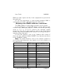
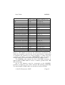
IQ-MX80
Features of the IQ-MX80
• Controls up to 16 NJD intelligent lighting
products independently.
• Controls:
Predator MX and HX,
Chroma HX and Chroma 50,
Microbeam 100,
IQ250 (Mk.1, 2 & 3) ,
IQ500 (Mk.1 & 2),
Datamoon,
Spectre,
Raptor,
Quasar,
and SB500 Super Blitzer
• Joystick for manual operation or programming
• Touch pad control of colour and gobo.
• Ten built in programs
• Ten user-writable programs of 250 steps
• Real-time programming
• Strobe facility
• Lamp on/off facility (halogen lamps only)
User Guide
IQ-MX80
IMPORTANT
Installer and Users please note:
These instructions should be read carefully and left
with the user of the product for future reference.
Installation.
Connect the IQ-MX80 to the 230V mains supply with the lead
supplied.
• Brown = live • Blue = neutral • Green/Yellow = earth
• The IQ-MX80 must be earthed to ensure safety and
correct operation of the touch pads.
If sound activated operation is required, connect a sound
signal, either 0dBm from the line-level output of a mixer, or the
speaker output from an amplifier, to the sound input jack.
Great care should be taken not to connect the sound input to
the DMX-output socket, as this may destroy the internal
electronics (the DMX line-driver)
Connect the DMX output from the IQ-MX80 to the DMX input
of the nearest lantern. The DMX output socket is a 3-pin XLR. Pin
connections are as follows:
Pin 1 = ground
connect to sleeve on stereo ¼" jack
Pin 2 = Data +
Pin 3 = Data −
or Pin 1 on 5-pin XLR
connect to tip on stereo ¼" jack
or Pin 3 on 5-pin XLR
connect to ring on stereo ¼" jack
or Pin 2 on 5-pin XLR
On a 3-pin XLR, Pin 3 is the one in the middle.
Refer to the “externally controlled” section of the lantern user
guide for further information on connection.
Portable Appliance Testing
The IQ-MX80 should be checked for Electrical Safety annually,
and if it is hire equipment, before it is hired out. A high-voltage
test (at 500V or 1000V) should be carried out between live and
earth, and an earth bonding test between the case and the earth
connection (at 6A or 10A). Insulation resistance should be
greater than 10MW and earth bonding resistance less than
0.5W. A high voltage test may also be carried out between the
© N.J.D. Electronics 1997
-Page 2-
User Guide
IQ-MX80
DMX and audio inputs and live, if the equipment has passed the
live-earth test.
Do not test high-voltage or earth bonding between DMX or
audio inputs and earth - this will destroy the electronics.
Setting the DMX address switches.
The DMX switches on the lantern should be set as shown.
If your lantern has a 3-digit LED display, set the display to the
number in the "DMX start address" column, and set the operating
mode to "F 1" or "F 3" (F 3 reverses the left-right joystick
movement. This allows the joystick to work in the most logical
fashion, depending on whether the lanterns are facing towards or
away from the controller).
If it has DIL switches, refer to the "switches ON" column. If
there are also switches labelled "MODE" (e.g. Spectre) set them
to the "IQ-MX80" setting
Note: The switch numbers refer to the numbers printed on
the product label adjacent to the switch, not to the numbers on
the switch itself.
Lantern number
DMX
Switches ON
start address (other switches off)
1
1
None
2
9
8
3
17
16
4
25
16, 8
5
33
32
6
41
32, 8
7
49
32, 16
8
57
32, 16, 8
9
65
64
10
73
64, 8
11
81
64, 16
12
89
64, 16, 8
13
97
64, 32
. . .continued overleaf
© N.J.D. Electronics 1997
-Page 3-
User Guide
IQ-MX80
Lantern number
DMX
Switches ON
start address (other switches off)
14
105
64, 32, 8
15
113
64, 32, 16
16
121
64, 32, 16, 8
1 (reversed in X direction)
5
4
2 (reversed in X direction)
13
8, 4
3 (reversed in X direction)
21
16, 4
4 (reversed in X direction)
29
16, 8, 4
5 (reversed in X direction)
37
32, 4
6 (reversed in X direction)
45
32, 8, 4
7 (reversed in X direction)
53
32, 16, 4
8 (reversed in X direction)
61
32, 16, 8, 4
9 (reversed in X direction)
69
64, 4
10 (reversed in X direction) 77
64, 8, 4
11 (reversed in X direction) 85
64, 16, 4
12 (reversed in X direction) 93
64, 16, 8, 4
13 (reversed in X direction) 101
64, 32, 4
14 (reversed in X direction) 109
64, 32, 8, 4
15 (reversed in X direction) 117
64, 32, 16, 4
16 (reversed in X direction) 125
64, 32, 16, 8, 4
If the lantern has switches labelled "1", "2" or "128", set
these to OFF. Switch 4 reverses the X-direction movement. This
allows the joystick to work in the most logical fashion, depending
on whether the lanterns are facing towards or away from the
controller. Predators and later IQ250/IQ500 have an extra xreverse switch. For these lanterns set the "4" switch to OFF.
The IQ-MX80 only outputs the first 128 DMX channels. A
lantern with its DMX address set to a number greater than 128
will not function.
Up to 32 lanterns may be connected to the IQ-MX80.
Lanterns assigned to the same channel will perform identically.
The total length of DMX cable run should not exceed 250m
© N.J.D. Electronics 1997
-Page 4-
User Guide
IQ-MX80
Operation.
When the IQ-MX80 is first turned on from new, it will start in
Manual mode, the display will show - - - - - and the manual LED
will be lit. On subsequent occasions, when the IQ-MX80 is
switched on, it will resume operation from where it was switched
off, allowing it to be turned on and off remotely and operate
automatically in situations where an operator is not available.
Manual Mode
In manual mode, the user has direct control over any number
of the lanterns with the colour and gobo touch pads and the
joystick.
First select the colour and gobo required. To select split
colours, touch two adjacent pads: i.e. to select red/green split,
touch red and green together. To select colour scrolling, set the
scrolling speed on the speed control and then touch magenta and
white together.
Then select the lanterns required by touching the lantern
select pads. The selected colour and gobo will then be assigned to
the selected lanterns. The joystick will then control the movement
of the selected lanterns. The colour and gobo must be selected
first. This allows several cans to be controlled simultaneously by
the joystick, but with different colours and gobos.
Whenever a lantern is selected it takes the colour and gobo
selected on the colour/gobo keypad. The joystick controls the
movement of all selected lanterns.
To change the colour and gobo, change the colour and gobo,
deselect the lantern by touching the lantern select pad, and then
re-select the lantern.
When a lantern is de-selected, it remains in the last position
set on the joystick. This allows all lanterns to be positioned
individually.
To select strobe touch blackout and l together. If selecting
strobe on the Microbeam, Datamoon or IQ250, first select white;
otherwise these products will attempt to strobe in other colours
and will not be too successful. The Predators, Chroma HX and
IQ500 can strobe in any colour.
In manual mode, the blackout pad turns the lamp off on
© N.J.D. Electronics 1997
-Page 5-
User Guide
IQ-MX80
products with halogen lamps; on products with Metal Halide
lamps, the lamp continues to run and is blacked out by a shutter.
Short-cut: to change the colour and gobo of all selected
lanterns, select the new colour and gobo and touch the run pad.
Use with various lanterns
• Predator HX/MX
all features are available
• IQ500
Split colours and colour scrolling are not available
• Microbeam, IQ250
Gobo pads have no effect (except for blackout and strobe)
• Datamoon.
Joystick x-axis controls dish rotation, y-axis has no effect. Split
colours and colour scrolling are not available. Gobo pads have no
effect (except for blackout and strobe)
• Chroma HX / Chroma 50
Joystick x-axis has no effect, y-axis controls dimming. Some
split colours and colour scrolling are available, but gobo pads have
no effect (except blackout and strobe)
The IQ-MX80 is not compatible with the Chroma 250.
• Raptor
Joystick x-axis controls barrel rotation, y-axis controls barrel
left-right movement. Split colours are available.
• Quasar
Joystick x-axis controls dish rotation, y-axis controls dish leftright movement. Split colours are available.
• SB500 Super Blitzer
Joystick x-axis controls dish rotation, y-axis controls dimming.
Colours and gobos have no effect (except blackout and strobe)
Running programs.
Switch off manual mode by touching the MAN. pad.
The display will now show the program number and the step
number in the program. Select the program number by touching
the PROG pad. Programs 1 to 10 are factory written programs
and cannot be overwritten. Programs 11 to 20 are user-writable
programs, and can be overwritten at any time if the write enable
© N.J.D. Electronics 1997
-Page 6-
User Guide
IQ-MX80
switch on the rear panel is in the "enable" position. A battery
inside the IQ-MX80 retains the user programs when the mains
power is disconnected, provided that the IQ-MX80 is used at least
once every 3 months.
Select the animation mode by touching the SOUND pad.
Green =sound animated
No led lit = variable speed animation - the speed is set on the
speed control
Red = stop/single step operation.
The lanterns will remain static, and will advance one step
when the STEP pad is touched.
When the IQ-MX80 reaches the end of the program it starts
again at the beginning. To run through all programs sequentially,
select run mode by touching the RUN pad. The run led will light.
The IQ-MX80 will run through each program four times and then
change to the next.
To return to manual mode, touch the MAN. pad. The IQMX80 will return to the lanterns and the colours that were
selected when manual mode was exited.
Short-cut:
To change programs quickly, touch the PROG pad and
touch the lantern select pad that corresponds to the number of
the program required before releasing the PROG pad. Only
programs 1 to 16 are available by this method.
Manual Override:
Whilst running programs, the lantern select and colour/gobo
pads can be used as in manual mode, to override the program.
The only difference is the scroll speed which is fixed. When the
lantern is de-selected it resumes running the program.
To remove certain lanterns from a program, select
BLACKOUT and select the lanterns to be removed.
Writing programs.
Programs 11 to 20 can be written by the user.
The write enable/disable switch on the rear panel must be in
the enable position.
Select write by touching the WRITE pad, the write LED will
flash. Select the required program by touching the prog pad, until
© N.J.D. Electronics 1997
-Page 7-
User Guide
IQ-MX80
the required program number appears in the display.
Set up the required colours, gobos and beam positions on the
lanterns for the first step of the program and touch ENTER.
The letter E appears in the step display to acknowledge that enter
has been touched. Touch STEP to advance to the next step in
the program. The lanterns will then display the settings previously
stored in the new step. To view the current settings of the joystick
and colour/gobo pads, touch RUN.
Repeat for the other steps in the program, up to a maximum
of 250 steps.
If programming fewer then 250 steps; after the last step,
Select lantern #1, touch STEP to advance to the next step, and
then touch END. The letter E appears in the program display to
acknowledge that end has been programmed.
It is most effective to program each lantern in turn. When
programming, lanterns that are not selected will display the
colours and positions that have already been programmed into
them.
Touch the WRITE pad again to exit from program-write
mode. Switch the write disable switch back into the disable
position to protect the programs that had been written.
When writing or running programs, the BLACKOUT pad
operates the shutter leaving the lamp on.
Real time programming.
The write enable/disable switch on the rear panel must be in
the enable position.
Select write by touching the WRITE pad, the write LED will
flash. Select the required program by touching the PROG pad,
until the required program number appears in the display.
If the program is not to involve all 16 lanterns, first clear the
program as follows: Select BLACKOUT and all 16 lanterns.
Set the joystick to the centre. Then touch START and wait until
the display counts to 250.
Set the colours and gobos and select the lanterns required.
Move the beams to the starting position using the joystick. When
ready, touch the START pad. The IQ-MX80 will record the
joystick position ten times per second, making a program of 250
© N.J.D. Electronics 1997
-Page 8-
User Guide
IQ-MX80
steps which is 25 seconds long. If the program needs to be
shorter, touch the END pad.
To change colours and gobos, select the new combination,
deselect then reselect the lantern by pressing the lantern select
pad twice; or, to change the colour and gobo of all selected
lanterns, touch the RUN pad.
Real time programs can be built up one lantern at a time, or
in groups, until all 16 channels are involved, by repeating the
programming process, selecting different lanterns. When
programming, the lanterns that are not selected, will display the
patterns that have already been written, allowing movement of
lanterns to be synchronized.
Editing programs
The write enable/disable switch on the rear panel must be in
the enable position.
Select the program to be edited using the PROG pad. Select
the step to be edited using the step pad. Set the colours and
gobos and select the lanterns to be edited. Move the beams to
the required position using the joystick and touch ENTER.
Extending programs.
Select the program to be edited using the PROG pad.
Using the STEP pad, select the step after the last step in the
existing program. Continue programming as above until the last
step of the new program is reached, and touch step to advance
to the next step, then select Lantern #1 and touch END.
Programs must be extended one step at a time, it is not possible
to extend programs using the real-time programming technique.
Shortening programs.
Select the program to be edited using the PROG pad. Using
the step pad, select the step which is one more than the last step
of the edited program and touch END.
Notes on DMX.
The DMX system is a high-speed digital data system, which
can transmit all the information required for light dimmers, multimotor lighting effects etc. down a single cable.
Each unit connected to the DMX signal is given an address,
and it compares this to the data being sent on the DMX cable, so
© N.J.D. Electronics 1997
-Page 9-
User Guide
IQ-MX80
it can determine which data is addressed to it. It then uses this
data to move a motor or set a brightness level as required by the
controller.
As the DMX system can transmit as much information as
512 analogue control wires down a single cable, it has to
transmit very quickly, in fact, at a frequency 12 times higher than
the highest audio frequency. Anyone who has used long leads for
audio will realise that it is difficult to do without losing the higher
frequencies.
To make the DMX system work at such high frequencies, it
requires special circuitry and special cable. Cable can be designed
to pass high frequencies with no loss if it has the correct
resistance connected at each end, this resistance is called the
characteristic impedance of the cable. DMX cable has a
characteristic impedance of 120W.
All NJD DMX products with ¼" jacks are designed to ensure
that the resistors are connected automatically. Without them, the
signal reflects off the end of the cable and interferes with the new
data coming the other way. If the cable is not correct, the system
will not work. Products with XLRs require a DMX terminator to be
fitted to the DMXout connector of the last lantern in the chain refer to the lantern user guide.
Most good quality low-capacitance screened twisted pair
cables will work, but twin individually screened will not. Also, if the
cable is split or joined other than end-to end, the system will stop
working.
Fault Finding
• Lanterns do not operate
Break in DMX cable between controller and first lantern.
DMX Cable shorted out*
DIL switch #128 turned on (should be off)
• Only certain lanterns operate
break in DMX cable*
DIL switch #128 turned on (should be off)
• Lanterns operate erratically
Unterminated cable in output socket of last lantern.
poor or intermittant DMX earth connection*
© N.J.D. Electronics 1997
-Page 10-
User Guide
IQ-MX80
Wrong cable specification.
• Joystick operates colour and gobos instead of beam
position
DIL switches on lantern set incorrectly (it is likely that switch
#2 is on when it should be off)
• Microbeam, Datamoon or IQ250 gobos cannot be
selected separately
It is not possible to select gobos separately on these products
• Other manufacturers' products do not operate
correctly
The IQ-MX80 is only intended to operate NJD lanterns
*A fault in the cable may affect lanterns anywhere in the DMX
chain, not necessaraily those adjacent to the fault.
Technical specification.
Dimensions:
Power supply:
Power requirements:
Mains input:
Fuse:
Sound input:
Impedance:
DMX output:
Channels
482 × 133 × 100 mm
230V AC 50Hz
9VA
IEC connector
F250mA 5 × 20mm HBC to IEC127.
(located inside mains input connector)
¼” mono jack
0.775V to 60V rms (0 to +40dBm)
15kW
3-pin female XLR
Data+ = pin 2
Data- = pin 3
Earth = pin 1
1-128
Standards:
The IQ-MX80 complies with the following standards:
EN60950 electrical safety
EN55103 electromagnetic compatibility
EN60297 fascia panel dimensions
RS-485 Digital transmission system
USITT DMX512 Lighting control protocol
© N.J.D. Electronics 1997
-Page 11-
User Guide
IQ-MX80
Guarantee
This product is guaranteed for a period of 12 months
against faulty components or manufacture from the date of
purchase. Upon proof of purchase, NJD shall, at its own
option, repair or replace the defective item at no cost to the
purchaser.
This guarantee is contingent upon the proper use of the
product in the application for which it is intended and does
not cover products that have been modified, subjected to
unusual physical conditions, or electrical conditions outside
its specification, or damaged in any way.
This guarantee is limited to the product only and does
not cover carriage costs, installation costs or travel
expenses. Your statutory rights are not affected.
In the event of any problems with this product contact
the retailer from which it was purchased for technical
assistance, or e-mail [email protected]
NJD Products are distributed by:
Electrovision Ltd.,
Lancots Lane,
Sutton Oak,
St. Helens,
Merseyside,
England.
WA9 3EX
Telephone: +44 1744 745000
Fax: +44 1744 745002
E-mail: [email protected]
Web sites:
www.njd.co.uk
www.electrovision.co.uk
© Copyright N.J.D. Electronics.
Neither the whole nor any part of the information contained
in, nor the product described in this User Guide may be adapted,
copied or reproduced in any form except with the prior written
approval of N.J.D. Electronics.
© N.J.D. Electronics 1997
-Page 12-