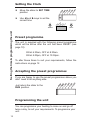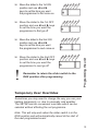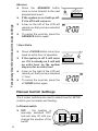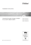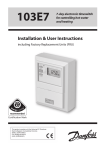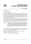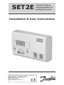
1
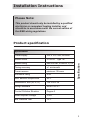
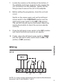
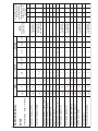
SET2E
electronic 24-hour
mini-programmer for
heating & hot water
Installation & User Instructions
Index
Installation
Product specification
3
Installation
4-5
Wiring
5-7
Replacement
7-9
INDEX
User
2
What is a Programmer?
10
Your programmer
11
Resetting the unit
11
Setting the clock
12
Factory pre-sets
12
Programming the unit
12-13
Temporary overrides
13-14
Manual switch settings
14-15
Memory back-up
15
Contact details
16
Installation Instructions
Please Note:
This product should only be installed by a qualified
electrician or competent heating installer, and
should be in accordance with the current edition of
the IEEE wiring regulations.
Product specification
Power supply
230 ± 15% Vac, 50/60Hz
Switch action
2 x SPDT Type 1B
Switch rating
Max 264Vac, 50/60Hz, 3(1) A
Timing accuracy
± 1 min/month
Power reserve
minimum 10 hours
Enclosure rating
IP30
Max. ambient temperature
45°C
Dimensions, mm (W, H, D)
158 x 98 x 38
Design standard
EN 60730-2-7
Control Pollution Situation
Degree 2
Rated Impulse Voltage
2.5kV
Ball Pressure Test
75°C
Specification
Specification
3
Installation
1.
Fix the wallplate to the wall or flush mounted box as
required. The connections are at the top and the
vertical centre line of the unit, at the position shown on
the diagram below C/L (in line with terminal )
Outline of
programmer
C/L
Leave sufficient space
for screwdriver access
Terminal
block
Wall or
plasterbox
fixing
Installation
Leave at
least 25mm
below
product
4
Rear entry
cable access
Cable aperture
knockouts
2.
Surface cables can only enter from below the unit. If
mounted on a flush mounted box, cables can enter
from the rear through the aperture in the wallplate.
3.
For mains voltage applications a link must be fitted
between terminals L and 2 and between 1 and 5.
4.
Whilst the unit does not require an Earth connection,
a terminal is provided on the wallplate for Earth
continuity purposes.
5.
Referring to the wiring diagrams on page 5-7, connect
the unit as shown.
6.
Ensure all dust and debris are cleared from the area.
7.
Locate the module on the latches at the bottom of
the wallplate and hinge upwards to fully engage the
unit connectors into the wallplate. Tighten the two
fixing screws to secure the unit to the wallplate.
8.
Before setting the programme, check the unit and
circuit.
Switch on the mains supply and set the left-hand
rocker switch to the CONSTANT position and the
right-hand rocker switch to the HW + CH position.
The red LED should now be illuminated. Adjust any
remote thermostats to check the services operate
correctly.
9.
Press the left-hand rocker switch to the OFF position
and check that both services do not operate.
Installation
10. Finally, return the left-hand rocker switch to TIMED
and the right-hand rocker switch back to HW + CH
(winter) or HW (summer).
Wiring
SET2E 07/05
SET2E
ON
DHW
OFF
HTG
NOTE: For mains voltage applications links must be fitted between
terminals L and 2 and between 1 and 5.
5
Given below are typical wiring diagrams for various types
of systems.
Note: Whilst every attempt has been made to ensure the accuracy of this
information it is recommended that the specific information relating to the
ancillary controls is obtained from the manufacturers concerned.
Typical Gravity DHW
with pumped central heating
OFF ON
ON
Programmer
Terminals
HTG
D.H.W.
N
L
1
2
3
4
OFF
5
6
Mains
Supply N
L
3 amp fuse
N
Room
Stat
L
DHW = Domestic
Hot Water
N
Boiler
N
Pump
Wiring
Typical fully pumped system
with spring return zone valve in heating
HTG
D.H.W.
OFF ON
ON
Programmer
Terminals
N
L
1
2
3
4
Mains
Supply N
L
3 amp fuse
Room
Stat
Cyl.
Stat
N
L
Boiler &
Pump
6
N
N
HTG
valve
OFF
5
6
Typical fully pumped system
with 3-port mid-position valve
OFF ON
ON
Programmer
Terminals
N
HTG
D.H.W.
L
1
2
3
4
OFF
5
6
Mains
Supply N
L
3 amp fuse
Room
Stat
Cyl.
Stat
N
L
Boiler &
Pump
N
N
3-port
mid-pos
valve
Please see overleaf for a table containing replacement
wiring information.
Some controls are connected in different ways depending
upon the type of system and/or the controls which are
fitted. If there is any doubt about the way in which the
existing unit is connected, please contact our Technical
Services Department before proceeding with
replacement.
!
Wiring
Replacement
If the unit is to be used in association with a 6
wire Honeywell Y Plan, a special wiring diagram
may be required. Contact the Danfoss Randall
Technical Services Department for details.
Note: The SET2E is a direct replacement for a Danfoss
Randall SET2.
7
8
N
N
2,3
DANFOSS RANDALL 701
HONEYWELL ST6200
HORSTMANN CORAL 423 & 424
POTTERTON MINI-MINDER
POTTERTON 423
N
N
N
N
HORSTMANN DIAMOND 424
LANDIS & GYR RWB2
N
N
HORSTMANN DIAMOND 423
HORSTMANN DIADEM 525
N
5
DANFOSS RANDALL 102/102E
HORSTMANN DIADEM 425
1,7
3
N
N
N
MAINS
DANFOSS RANDALL 3060 & 3020P
DANFOSS RANDALL TSR2P
DANFOSS RANDALL SET 2
with terminals L - 2 and 1 - 5 linked
SET2E
DANFOSS RANDALL
L
L,1,3
L
L,1,3
L,1,3
L
L
1
L
L
3,6
6
1,2
L
L
L
3
2
3
2
2
1
1
Boiler (8)
3
3
1
4
5,6
1
1
ON
-
-
-
-
-
2
2
-
-
6
-
-
-
2
2
COM
WATER
1
-
1
-
-
3
3
-
1
4
-
-
-
3
3
OFF
4
4
4
4
4
4
4
AirStat (8)
4
1
2
2
7
4
4
ON
-
-
-
-
-
5
5
-
-
5
-
-
-
5
5
COM
HEATING
2
-
2
-
-
6
6
-
2
2
-
-
-
6
6
OFF
Programme
selectors linked
Programme
selectors linked
Programme
selectors linked
Programme
selectors linked
Terminals 1 & 2
are linked and
5 & 6 are linked
Direct plug-in
replacement
NOTE
This conversion
applies only if..
5
5
5
4,7
3
4
A
6
6
5
5
B
6
C
D
An additional terminal
block is required
where these disconnected leads (or pairs
of leads) should be
terminated
9
N
1
N
1
SMITH IND. CENTROLLER 100
SMITH IND. CENTROLLER 60
SMITH IND. CENTROLLER 10
SMITH IND. CENTROLLER 70
VENNER VENOTROL 80 (Air Stat
Linked)
VENNER VENOTROL 80 (Air Stat)
VENNER VENOTROL
N,1
3,4
N,1
3,4
N,A,M
N
N
SWITCHMASTER 600
SWITCHMASTER 900 & 9000
N
N
SWITCHMASTER 400
SWITCHMASTER 320 & 350
N
N,2
SANGAMO (EARLY MODEL)
S410 FORM 4
SMITH IND. CENTROLLER 1000
N,1,3
4,5
N
SANGAMO S409 FORMS 1 & 4
SANGAMO M5 410 FORM 4
POTTERTON EP2000
L
L
L,L,1
L
L
L
4,L
L
2
L
2
L
L
L
3
L
2
2
V
3
3
3
3
3
5
3
5
3
1,3
2
1,6
3
-
-
-
-
-
-
-
-
-
-
-
-
-
-
-
-
-
-
-
4
-
-
-
1
-
-
-
-
-
-
2
1
5
A/S
S,F
1
1
1
1
4
4
2
4
2
4
5
8
4
-
-
-
-
-
-
-
-
-
-
-
-
-
-
-
5
-
-
-
2
-
4
-
2
-
-
-
-
-
-
7
2
Programme
Selectors Linked
Terminals L & 4
are linked
Programme
selectors linked
Terminals 1 & 3
are linked
Terminals 1 & 6
are linked
Programme
selectors linked
A/
S,
5
T,P
A
2
2
2
3
1,4
3
1
4,6
A
O
B
4
6
4
B
C
C
D
The text below has been edited and approved by the
Plain English Campaign, who has issued a Crystal Mark
to be displayed with it.
What is a programmer?
What is a programmer?
... an explanation for householders.
Programmers allow you to set ‘On’ and ‘Off’ time periods.
Some models switch the central heating and domestic
hot water on and off at the same time, while others allow
the domestic hot water and heating to come on and go
off at different times.
Set the ‘On’ and ‘Off’ time periods to suit your own lifestyle.
On some programmers you must also set whether you
want the heating and hot water to run continuously, run
under the chosen ‘On’ and ‘Off’ heating periods, or be
permanently off.
The time on the programmer must be correct. Some
types have to be adjusted in spring and autumn at the
changes between Greenwich Mean Time and British
Summer Time.
You may be able to temporarily adjust the heating
programme, for example, ‘Override’, ‘Advance’ or ‘Boost’.
These are explained in the manufacturer’s instructions.
The heating will not work if the room thermostat has
switched the heating off. And, if you have a hot-water
cylinder, the water heating will not work if the cylinder
thermostat detects that the hot water has reached the
correct temperature.
10
User Instructions
Your programmer
The programmer provides 2 ON times and 2 OFF times per
day, and by the use of a simple rocker switch you can run the
system at the set times, constantly ON or constantly OFF.
During the summer the central heating can be turned off,
whilst still controlling the hot water at the set times.
X and
+1 HOUR
button
W and
ADVANCE
button
Slider
switch
Rocker
switches
Resetting the Unit
Your programmer & resetting the unit
The SET2E allows you to switch your hot water & heating
on and off automatically, at times that suit you.
IMPORTANT: Before you start you should reset the unit.
This will reinstate the preset programmes.
To do this:
move slide switch to SET TIME
position
using something non-metallic (i.e
a matchstick) press into the small
hole as shown opposite
RESET
11
Setting the Clock
Move the slider to SET TIME
position
Setting the time & programming the unit
Use W and X keys to set the
correct time
Preset programme
The unit is supplied with the following preset programme
which will be active after the unit has been RESET (see
page 10):
ON at 6:30am, OFF at 8:30am.
ON at 5:00pm, OFF at 10:30pm.
To alter these times to suit your requirements, follow the
instructions on page 12.
Accepting the preset programmes
If you are happy to use the preset programmes above you
don’t need to do anything else.
Just return the slider to the
RUN position.
Programming the unit
You can programme your heating to come on and go off
twice a day, to suit your requirements. To programme your
unit:
12
Move the slider to the 1st ON
position and use W and X
keys to set the time you want
the programmer to first come on
Move the slider to the 1st OFF
position and use W and X keys
to set the time you want the
programmer to first go off
Move the slider to the 2nd OFF
position and use W and X keys
to set the time you want the
programmer to next go off
!
Remember to return the slider switch to the
RUN position after programming
Programming the unit
Move the slider to the 2nd ON
position and use W and X
keys to set the time you want
the programmer to next come on
Temporary User Overrides
Sometimes you may need to change the way you use your
heating temporarily, i.e. due to unusually cold weather.
The SET2E has two convenient overrides which can be
selected without affecting the set programme.
Note: This will only work when the slider switch is in the
RUN position and will automatically cancel at the start of
the next programmed event.
13
Advance
Press the ADVANCE button
once to move forward to the next
programmed event
Temporary User Overrides and manual settings
If the system is on it will go off.
If it is off it will come on
A bar on the left of the LCD will
remind you that you have selected
Advance
To cancel the override, press the
ADVANCE button again
1 Hour Extra
Press +1 HOUR button once if you
need an extra hour of operation
If the system is off it will come
on. If it is already on it will add
an extra hour so the system
stays on for an extra hour
A bar on the right of the LCD will
remind you that you have selected
+1 hour
To cancel the override, press the
+1 HOUR button again
Manual Switch Settings
The 2 rocker switches are used to select how the SET2E
controls your hot water and heating:
Left-hand switch
OFF - the heating is
manually switched OFF
and will stay off until you
change the position of the
switch
14
TIMED - the heating will come on and go off at the
times you have programmed (including any temporary
overrides you may select)
CONSTANT - the heating will come on manually and
stay on constantly until you change the position of the
switch
HW + CH - both heating
and hot water are
controlled according to
the set programme
HW - heating is turned off
and only the hot water is
controlled according to
the set programme
Memory Backup
IMPORTANT
If the SET2E is ever disconnected from the mains the
display will go blank but the unit will keep your programme
time and settings for up to 10 hours.
Manual settings and memory backup
Right-hand switch
When power is restored the unit will continue to function
as normal.
For power cuts or disconnections of greater then 10 hours,
when mains power is restored you must reset the unit (see
page 10). This will reinstate the factory preset programmes
and set the time of day to noon.
15
Still having problems?
Call your local heating engineer:
Name:
Tel:
Visit our website:
www.danfoss-randall.co.uk
Email our technical department:
[email protected]
Call our technical department
0845 121 7505
(8.45-5.15 Mon-Thurs, 8.45-4.45 Fri)
For a large print version of these
instructions please contact the Marketing
Services Department on 0845 121 7400.
Danfoss Randall Ltd
Ampthill Road
Bedford
MK42 9ER
Tel: 01234 364621
Fax: 01234 219705
Part No. 8657 Issue 05 02/06
SW REV 6.1