1
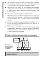
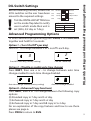
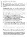
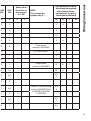
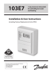
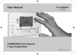
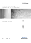
FP715 Si Electronic, 2-channel full programmer for heating & hot water with service interval timer Installation & User Instructions (Including 24V Models) ® Certification Mark Index Index Installation Instructions Product specification and Installation Installation and Wiring DIL switch settings Advanced Programming Options Copy Functions Service Interval Timer Wiring Conversion User Instructions What is a Programmer? Your programmer Preset programmes Resetting the unit 24hr or AM/PM display Setting the Date, Time and Day Accepting the preset programmes Changing the preset programmes Programming heating - 5/2 day Programming heating - 7 day Programming heating - 24 hour Programming hot water Running the programme Temporary overrides Holiday Programme Changing clocks forward/back Service Interval Timer Fully Resetting the Unit Troubleshooting Contact details 3 4 5 5 6-7 7 8-15 16 17 17 18 18 18-19 19 20 21-22 23-24 25 26 27 28 29 30 31 32 34 36 Central Heating 1HR override Central Heating MAN override Hot Water 1HR override +1HR +1HR MAN MAN DAY/HOL Hot Water MAN override Hot Water Mode SELECT Central Heating Mode SELECT RESET 2 Please Note: This product should only be installed by a qualified electrician or competent heating installer, and should be in accordance with the current edition of the IEEE wiring regulations. Product specification Specification Power supply Switching action Unit switch rating Battery back-up Programme resolution 230V model 24V model 230 Vac, 24 Vac, ±15%, ±15%, 50/60 Hz 50/60 Hz 2 x SPDT internally linked, Type 1B 230 Vac, 3(1)A 24Vac, 3(1)A 24 hours minimum ± 1 minute Dimensions, mm (W, H, D) 135 x 88 x 32 Design standard EN 60730-2-7 Control Pollution Situation Installation & Specification Installation Instructions Degree 2 Rated Impulse Voltage 2.5 kV Ball Pressure Test 75°C Installation Remove wallplate from unit by unscrewing the two screws on the bottom edge of the unit. From the top left hand corner of the wallplate, there must be clearances of at least 140 mm to the right, 15mm to the left, 30mm above and 100mm below in order to mount the plug-on module. 3 Installation and Wiring The wallplate must be securely mounted either directly to the wall using suitable wood screws or to a flush mounted 1-gang electrical accessory box using M3.5 screws. Cable access can either be from behind for concealed cabling, or from below for surface cabling. If surface cable is used, cut out cable access slot on plug-on module prior to mounting. For wiring connections refer to diagram below. FP715 Si models are double insulated and do not require an earth connection, however a parking terminal is provided on the wallplate. This is clearly marked with an Earth symbol. Prior to mounting the plug-on module, DIL switches on the rear of the plug-on module must be set. See diagram on page 5 for available options. Mount plug-on module to wallplate by locating tabs on top of wallplate in apertures on rear of module, hinge down and press firmly to wallplate before tightening securing screws on bottom of wallplate. Wiring (For Wiring Conversion tables see - pages 8-15) ELECTRONICS N/C Please Note: On 24 volt models power supply must be wired to A & B on wallplate. N/O N/C N/O N L 1 2 3 4 230V Fused 3A OFF DHW OFF ON HTG DHW ON HTG Always switch off mains first and never fit programmer to a live wallplate. 4 Before mounting the unit, ensure the 4 DIL switches on the rear have been moved to the required settings. Tick the INSTALLER SETTING box on the inside flap label to notify user in which mode their unit is set (24hr, 5/2 day or 7 day). ! Sw.1 Not Used Sw.2 Gravity Pumped Sw.3 5/2 Day 7 Day or 24 Hour Sw.4 7 Day Not Used 24 Hour INSTALLER SETTING 24 Hour 5+2 Day 7 Day Advanced Programming Options To enter advanced programming press PROG, + and DAY/HOL together and hold for 5 seconds. Option 1 - (3 or 2 On/Off ’s per day) Use + or - to change between 3 or 2 on/off ’s each day. 3 3 on/off ’s each day (Factory setting) 2 2 on/off ’s each day Option 2 - (Disable or enable auto time change) Press NEXT, then use + or - to change between auto time change enabled to auto time change disabled. Auto time change enabled (Factory setting) Auto time change disabled Option 8 - (Advanced Copy Functions) Press NEXT, then + or - to change between the following copy options: (0) Standard copy in 7 day and 5+2 day. (1) Enhanced copy in 7 day and 5+2 day (2) Enhanced copy in 7 day and AB copy in 5+2 day. For an explanation of the copy features and how to use them please see page 6. Press PROG to return to RUN. DIL switch settings and Advanced Programming Options DIL Switch Settings 5 Copy Functions Copy Functions Explained There are 3 possible copy functions available. These are; Standard Copy, Enhanced Copy, and AB copy. Copy functions are enabled/disabled in the Advanced Programming Options (page 5). Standard Copy: Pressing copy will copy the previous days events into the displayed day. The unit will then display the 1st event for the new day. This copy function is present only if the unit is set to run in 5+2 or 7 day mode. Enhanced Copy: The enhanced copy function is available in 7 day mode only. This allows any day to be copied to any other day, or days. To use the enhanced copy function go into the event programming using the PROG button, then: 1. Use the DAY button to find the day to be copied from. 2. Press the COPY button to select the day to be copied from. When selected, the day should begin to flash. 3. Use the DAY button to find the day to be copied to. 4. Press COPY button to copy the selected day. 5. Repeat steps 3 and 4 to select and copy other days. 6. To stop copying, use the DAY button to go back to the flashing day and press the COPY button. The previously flashing day will stop flashing to indicate it has been deselected. NOTE: When a day has been copied to, it will remain visible and not flashing when the DAY button is used to select other days. AB Copy: The AB copy function is available in 5+2 mode only and only if activated in the Advanced Programming setting. 6 A and B days, when selected, can be any group of days e.g. 5+2, 4+3 etc. The days do not have to run in sequence. For example, to operate in a 5+2 day mode the days can be set as follows: B Days Wed Sun To use the AB copy function – press the PROG button: 1. This will show the “A” days, with all the days selected. 2. Use the DAY button to highlight a day. 3. Subsequent presses of the DAY button will increment through the days. 4. Press the + button to select a specific day as an “A” day, or press the – button to specify a day as a “B” day. 5. Once the day has been selected as an “A” or “B” day the programme will automatically jump to the next day. 6. When the last day of the week is active, pressing +, -, or DAY will move back to the “A” days displayed with no selected (flashing) days (see image below). 7. Repeat 2 to 6 until all selections have been made. 8. When selections are completed, press the PROG button to move to event programming. Event Programming in AB mode 1. Programme “A” day events using the + (time advance), - (time decrease), and NEXT (next period) buttons. 2. Press the DAY button to change to programme the “B” days 3. Programme “B” day events using the + (time advance), - (time decrease), and NEXT (next period) buttons. DIL switch settings and Advanced Programming Options A Days Mon Tues Thurs Fri Sat Service Interval Timer The FP715 Si is fitted with an installer setback service interval timer. If this feature is required please contact our technical department. Setting instructions for this gas safety feature are only available to bona fide heating installers. 7 Wiring Conversions Wiring Conversions, (applies only to 230 volt models) Wiring conversions can be used when replacing the following programmers with the FP715 Si. Some time controls are connected differently depending on the type of system they are controlling. Consult the column headed “NOTE This conversion ...” to determine whether Table A (pages 8-11) or Table A MAINS 8 DHW OFF HTG OFF DHW ON DANFOSS RANDALL FP715, CP715 (PUMPED) N L 1 2 3 DANFOSS RANDALL 922/972 N L 1 4 3 DANFOSS RANDALL 4033 7 6 5 3 4 DANFOSS RANDALL SET 5 N L 3 6 1 HORSTMANN 423, AMETHYST 7 & 10 2,3 1 4 6 5 HORSTMANN 424 GEM 2,3 1,10 6 9 4 HORSTMANN LEUCITE 423 & 424 2 1 4 8 3 HORSTMANN 425 DIADEM N L 3 6 1 HORSTMANN 525 & 527 N L 3 6 1 HONEYWELL ST669 N L 7 4 6 HONEYWELL ST6300 & ST6400 N L 1 2 3 PEGLER SUNVIC SP50/SP100 N L 1 4 2 POTTERTON EP2000, EP3000 N L 1 2 3 RANDALL TSR3+3 3,6 7 2 5 1 RANDALL 3033 1,7 6 5 3 4 RANDALL 702 N L 4 2 3 SANGAMO FORM 1 410 & 414 4,5 6 2 7 1 N,1,3 L - - 2 SANGAMO S409/1 HTG ON Wires other than links in these terms go to LIVE NOTE This conversion applies only if.... 4 L L 6 2 5 2 1 - 4 2 5 7 - - 7 5 8 Terminals 5,8 & 10 are LINKED 6 5 7 Terminals 5 & 7 are LINKED 4 2 5 Programme selectors UNLINKED 4 2 5 Programme selectors UNLINKED 3 8 5 4 - - 5 3 - 4 - 5 4 - - 2 - - 1 6 5 8 3 - 5 - - An additional terminal block may be required where these disconnected leads (or pairs) should be terminated A B C D C D Wiring Conversions Table B (pages 12-15) should be used. If in any doubt, contact our Technical Services Department before proceeding with the replacement. *Any wires connected to switch COMMONS which are linked LIVE on existing wallplates must be transferred to the LIVE terminal on the new wallplate. Programmed selectors UNLINKED 8 Programme selectors UNLINKED S S A B 9 Wiring Conversions 10 Table A cont.. DANFOSS RANDALL FP715, CP715 (PUMPED) MAINS DHW OFF HTG OFF DHW ON N L 1 2 3 3,6 7 4 2 5 SATCHWELL LIBRA & DHP 2201 1 2 8 5 6 SATCHWELL ET 1401 & 1451 1 2 8 5 7 SMITHS IND. CENTROLLER 90 1 2 - - 5 SMITHS IND. CENTROLLER 1000 N L 1 2 3 SWITCHMASTER 800 & 805 N L 4 2 3 SWITCHMASTER 900 & 9000 N L 4 2 3 SWITCHMASTER SONATA N L 3 6 1 VENNER CHC/W2 (WITH STAT) N,2,4 L - - 1 VENNER CHC/W2 (AIR STAT LINKED) N,2,4 L - - 1 VENNER VENOTROL 80M & 80PM (WITH AIR STAT) N,3 L 1 4 2 VENNER VENOTROL 80M & 80PM (AIR STAT LINKED) N,3 L 1 4 2 SANGAMO S409/3 HTG ON 4 L L 1 - - 3 7 4 4 6 3 4 - - 4 - - 1 - - 1 - - 4 - - A/S - - 3 - - A/S - - 5 - - NOTE This conversion applies only if.... An additional terminal block may be required where these disconnected leads (or pairs) should be terminated A B 3 6 A B C D Wiring Conversions W Wires other than links in these terms go to LIVE Programme selectors UNLINKED Programme selectors UNLINKED Used in a system having independent control of water and heating C A/S 3 A/S 5 11 Wiring Conversions Table B DANFOSS RANDALL FP715, CP715 (PUMPED) DHW OFF HTG OFF N L 1 2 DANFOSS RANDALL 922/972 N L 1 4 DANFOSS RANDALL 102/102E/102E7 5 3,6 - - HORSTMANN 423 DIAMOND POTTERTON 423 N L,1,3 - - HORSTMANN 424 DIAMOND N L,1,3 - - HORSTMANN CORAL 423 & 424 2,3 1 - - HORSTMANN 425 DIADEM N L 3 6 HORSTMANN 525 & 527 N L 3 6 HONEYWELL ST669 N L - - POTTERTON EP2000, EP3000 N L 1 2 RANDALL TSR2P 3 1,2 - - RANDALL MKII R6 3 1,2 - - DANFOSS RANDALL 3060 & 3020P 1,7 6 - - RANDALL 701 N L 4 2 DANFOSS RANDALL SET 2 N L 3 6 SANGAMO M5 410 FORM 4 4,5 3 2 7 N,1,3 L - - N,2 L - - 1 2 8 5 SANGAMO S409 FORMS 1 & 4 SANGAMO (EARLY MODEL) S410 FORM 4 SATCHWELL LIBRA 12 MAINS D BO DHW ON HTG ON 3 4 L L 3 6 2 5 1 2 - - 2 4 - 2 4 NOTE This conversion applies only if.... An additional terminal block may be required where these disconnected leads (or pairs) should be terminated A B - 5 6 - - 5 AIR STAT (8) - - 4,7 5 6 1 4 2 5 Programme selectors UNLINKED 1 4 2 5 Programme selectors UNLINKED 8 7,3 6 5 ...set for gravity HW 3 4 - 5 Programme selectors UNLINKED A B C 5,6 7 - - 1 & 2 are LINKED 5 & 6 are LINKED 4 4 5 - - 6 7 4 2 - - 3 5 3 1 6 5 1,5 4 2 - With Links L-2 & 1-5 1,6 8 - - 1 & 6 are LINKED 2 5 - - 1,3 4 - - 6 3 7 4 OILER (8) C D Programmed selectors UNLINKED Wiring Conversions Wires other than links in these terms to LIVE D 6,4 1 & 3 are LINKED 13 Wiring Conversions Table B cont... DANFOSS RANDALL FP715, CP715 (PUMPED) DHW OFF HTG OFF N L 1 2 SMITHS IND. CENTROLLER 1000 N L - - SMITHS IND. CENTROLLER 60 1 2 - - SMITHS IND. CENTROLLER 10 N L - - SMITHS IND. CENTROLLER 70 1 2 - - SMITHS IND. CENTROLLER 1000 N L 1 2 SWITCHMASTER 320 & 350 N 4,L - - SWITCHMASTER 400 N L - 4 SWITCHMASTER 600 N L - - SWITCHMASTER 900 & 9000 N L 4 2 N,A,M L,L,1 - - VENNER VENOTROL 80 (AIR STAT) N,1, 3,4 L - - VENNER VENOTROL 80 (AIR STAT LINKED) N,1 3,4 L - - VENNER CHC/W2 (WITH STAT) N,2,4 L - - VENNER CHC/W2 (AIR STAT LINKED) N,2,4 L - - VENNER VENOTROL 80P (WITH AIR STAT) N,1,3 L - 4 VENNER VENETROL 80P (AIR STAT LINKED) N,1,3 L - 4 VENNER VENTROL 14 MAINS DH O An additional terminal block may be required where these disconnected leads (or pairs) should be terminated HW ON HTG ON 3 4 L L A B 3 2 - - 1 4 5 4 - - 3 3 2 - - 1,4 5 4 - - 3 3 4 - - Programme selectors UNLINKED 3 1 - - L & 4 are LINKED 3 1 - - 2 3 1 - - 2 4 3 1 - - A B V S,F - - T,P O 2 A/S - - A/S 5 2 5 - - 1 A/S - - 1 3 - - 2 A/S - - A/S 5 2 5 - - 6,4 NOTE This conversion applies only if.... Programme selectors UNLINKED Used in a system having control of WATER ONLY or WATER & HEATING TOGETHER C D Wiring Conversions Wires other than links in these terms to LIVE 6 2 C A/S 3 15 What is a programmer? The text below has been edited and approved by the Plain English Campaign, who has issued a Crystal Mark to be displayed with it. What is a programmer? ... an explanation for householders. Programmers allow you to set ‘On’ and ‘Off ’ time periods. Some models switch the central heating and domestic hot water on and off at the same time, while others allow the domestic hot water and heating to come on and go off at different times. Set the ‘On’ and ‘Off ’ time periods to suit your own lifestyle. On some programmers you must also set whether you want the heating and hot water to run continuously, run under the chosen ‘On’ and ‘Off ’ heating periods, or be permanently off. The time on the programmer must be correct. Some types have to be adjusted in spring and autumn at the changes between Greenwich Mean Time and British Summer Time. You may be able to temporarily adjust the heating programme, for example, ‘Override’, ‘Advance’ or ‘Boost’. These are explained in the manufacturer’s instructions. The heating will not work if the room thermostat has switched the heating off. And, if you have a hot-water cylinder, the water heating will not work if the cylinder thermostat detects that the hot water has reached the correct temperature. 16 Your programmer The FP715 Si allows you to switch your heating and hot water on and off at times that suit you. Your programmer has had the date and time set up during manufacture and will automatically change between Greenwich Mean Time and British Summer Time. You can programme up to 3 ON/OFF times per day for the heating and the hot water and the two systems can be operated independently. Overview & Preset Programmes User Instructions Preset Programmes Your FP715 Si comes ready programmed with a set of operating times which often suit most people. Event No. Hot Water & Heating Mon-Fri Sat-Sun** 1 1st ON 6:30 7:30 2 1st OFF 8:30 10:00 3* 2nd ON* 12:00* 12:00* 4* 2nd OFF* 12:00* 12:00* 5 3rd ON 17:00 17:00 6 3rd OFF 22:30 22:30 * Not applicable if unit set to 2 ON/OFF’s per day by installer **Not applicable if unit set to 24 hour mode by installer See page 20 for explanations of different settings If you want to change any of these settings, you can do so by following the instructions on pages 20-26. First, follow the steps on page 18-19 to set the correct time and date. 17 RESET, 24hr or AM/PM display, Setting Date and Time Before you start Open the flap on the front of the clock. Press the RESET button using a non-metallic object (e.g. pencil/matchstick) until you hear a click and the 2 red lights on the front of the unit flash once. DAY/HOL This will stop and restart the electronics, without losing the factory set time and date settings. To fully reset the unit see page 32. Choice of 24hr or AM/PM display Press and hold DAY/HOL & NEXT ON/OFF for 1.5 seconds to toggle between 24hr clock and AM/PM display, as required. DAY/HOL Setting the Date and Time These settings are made during manufacture and only need to be made in the unlikely event that the unit has lost the settings. DAY/HOL DAY/HOL Setting the Date Press and hold PROG for 5 seconds to display year. Use the + or - buttons to set the correct year. 18 Setting Day, Accepting Preset Programmes Press DAY/HOL to display day and month. Use the + or - buttons to set the correct month (Jan = 1, Feb = 2 etc.). Press DAY/HOL to display day and month. Use the + or - buttons to set day of month. Press PROG to display the time. The words SET TIME will appear at the top of the display & the time will flash on and off. Use the + or - buttons to set the correct time (press and hold to change in 10 min. increments). Setting the Day The day of the week is set automatically. Accepting the preset programmes If you are happy to use the preset programmes on page 17, you don’t need to do anything else. 7 Press the PROG button once to return to run mode. 19 Changing Preset Programmes Before you change the preset programmes Your installer will have set your unit to operate in one of the following modes: 5/2 day - one set of programmes for weekdays and another for weekends (page 21-22) 7 day - different settings for each day of the week. (page 23-24) 24 hour - one set of programmes for the whole week. (page 25) ! See INSTALLER SETTING tick box on inside flap label to ascertain which mode your unit is set . INSTALLER SETTING 24 Hour 5+2 Day 7 Day Please Note The unit must be programmed in sequence and ON/OFF times cannot be set out of sequence. If you want to leave a preset time as it is, simply press NEXT to move on to the next setting Your installer will have set your unit to programme either 2 or 3 ON/OFF’s per day. If your clock has been installed to allow 3 ON/OFF’s and you do not wish to use one of the ON/OFF settings, simply programme the ON time to be the same as the OFF time and the setting will not operate. 20 1. Press PROG once until SET CH ON TIME appears at the top of the display and MOTUWETHFR appears at the bottom of the display. DAY/HOL Use the + or - buttons to set the time you would like your heating to first come on in the morning (Event 1). 2. Press NEXT ON/OFF once only. Use the + or - buttons to set the time you want your heating to go off (Event 2). DAY/HOL Programming heating - 5/2 day mode Programming the heating in 5/2 day mode DAY/HOL To move to the next setting, i.e. when you would like your heating to come on again (Event 3) press the NEXT ON/ OFF button again. 3. Continue programming the central heating ON and OFF times for weekday Events 4, 5 & 6 as in Step 2. 21 Programming heating - 5/2 day mode 4. Press the DAY/HOL button once and SASU will appear at the bottom of the display. If the same programme is required press the COPY button and the previous days programme will be entered. DAY/HOL If a different programme is required repeat steps 2-4. 5. Press the PROG button once to enter hot water programming or twice to return to run mode. 6. Proceed to page 27. Please Note If this setting is made on a weekend day SASU will show in place of MOTUWETHFR 22 DAY/HOL DAY/HOL 1. Press PROG once until SET CH ON TIME appears at the top of the display. Note the current day is displayed. Press the DAY/HOL button until the required day is displayed. 2. Use the + OR - buttons to set the time you want your heating to first come on in the morning (Event 1). 3. Press NEXT ON/OFF to move to Event 2. 4. Continue programming the central heating ON and OFF times in this way by using the + or - buttons to set the time you want and pressing the NEXT ON/OFF button to move to the next setting. 5. Press DAY/HOL button once only. The next day will appear at the bottom of the display. Repeat steps 2-5. DAY/HOL DAY/HOL Programming heating - 7 day mode Programming the heating in 7 day mode DAY/HOL DAY/HOL 23 Programming heating - 7 day mode 24 6. 7. Press the PROG button twice to return the unit to RUN mode (time appears & colon in the display begins to flash). Proceed to page 27. DAY/HOL 1. Press PROG once until SET CH ON TIME appears at the top of the display. DAY/HOL Use the + OR - buttons to set the time you want your heating to first come on in the morning (Event 1). 2. Press NEXT ON/OFF to move to Event 2. Continue programming the central heating ON and OFF times by pressing: DAY/HOL Programming heating 24 hour mode Programming the heating in 24 hour mode a) NEXT ON/OFF button to move to the next setting, b) + OR - buttons to amend the time. 3. 4. Press the PROG twice button to return the unit to RUN mode (time appears & colon in the display begins to flash). DAY/HOL DAY/HOL Proceed to page 27. 25 Programming hot water Programming the hot water To set the hot water programme press the PROG button twice until SET HW ON TIME appears on the display. DAY/HOL Set the hot water programme in the same way as the heating programme, using: DAY/HOL a) + and - buttons to alter the time, b) Pressing the NEXT ON/OFF button to move to the next setting, c) Pressing DAY/HOL to advance through days of the week (7 day mode) or to advance to Saturday and Sunday programming (5/2 day mode) and repeat steps a-c. Finally press PROG once to return the unit to run mode (time appears & colon in the display begins to flash). 26 DAY/HOL DAY/HOL DAY/HOL To run the central heating programme: press the SELECT button next to the radiator symbol until AUTO is displayed in the LCD. RUN mode Running your Programme To run the hot water programme: press the SELECT button next to the tap symbol until AUTO is displayed in the LCD. As you press the SELECT button the display will change between ON, OFF, ALLDAY and AUTO. ON OFF ALLDAY AUTO = the heating/hot water will come on and go off at the programmed times. ON = the heating/hot water will remain on constantly. OFF = the heating/hot water will not come on. ALLDAY = the clock will turn the heating/hot water on at the first programmed ON and will leave it on until your last programmed OFF. Select the option you require depending on your circumstances, time of year, etc. 27 Override buttons Temporary override buttons Sometimes you may need to change the way you use your heating temporarily, i.e. due to unusually cold weather. The FP715 Si has two convenient overrides which can be selected without affecting the set programme. +1HR +1HR MAN +1HR +1HR MAN MAN MAN The grey buttons next to the radiator symbol are the Heating override buttons. The grey buttons next to the tap symbol are the Hot Water override buttons. 28 +1HR Pressing this button when either system is in AUTO or ALLDAY mode will cause the heating/hot water to remain on for an extra hour. If it is pressed while the programme is OFF the heating/hot water will come on immediately for 1 hour then go off again. +1HR will be shown in the display. MAN Pressing this button when either system is in AUTO or ALLDAY mode will cause the heating/hot water to go OFF until the next programmed ON, or vice versa. MAN will be shown in the display. To automatically bring the heating back on when returning from holiday the FP715-Si has a built in holiday feature. Follow the steps below to set the date that the heating system needs to come back on. 1. Press DAY/HOL 2. Use the + OR - buttons to select the year. 3. Press DAY/HOL, then use the + and - buttons to select the month. 4. Press DAY/HOL again, then use the + and - buttons to select the day in month. 5. Press DAY/HOL to turn heating off and enter holiday mode. Holiday Mode Holiday Programme DAY/HOL DAY/HOL To cancel holiday mode press DAY/HOL. 29 Changing Clocks forward & back (Summer/Winter) Changing clocks forward & back This is handled automatically. Should the installer have turned off Automatic Time Change then follow the instructions below. Open the flap on the front of the unit to reveal the programming buttons. To change from Summer to Winter (clocks back) press and hold - button To change from Winter to Summer (clocks forward) press and hold + button ! 30 Take care when making this change for the first time. If it is made in the wrong direction the unit will have to be reset and any user-settings re-entered (see pages 18-19 on how to reset the unit and how to set the date, time and day). If the property is owned by a landlord he may, for gas safety reasons, have instructed the installer to set the service interval timer. If set, 28 days prior to the boiler service due date, a momentary visual and audible warning will remind you to have the boiler serviced in the next 28 days. This will be repeated each day at noon. Service Interval Timer Service Interval Timer If the boiler is not serviced within 28 days the daily audible warning will sound for 1 minute at the beginning of each hour and must be cancelled each day by pressing any button on the unit. In addition, all overrides and programming buttons will be disabled and the heating and hot water will operate for a set portion of each programmed hour. The installer will cancel or reset the service interval timer as part of the boiler service. This is a gas safety feature that can only be accessed by an installer. When the service interval timer is set the service due date can be viewed in RUN mode by pressing and holding the COPY button. 31 Fully Resetting the Unit Making a Full Reset If it is necessary to fully reset the unit, excluding the date and time, follow the instructions below. 1. Press and hold the +1HR and MAN buttons on the left hand side of the product. +1HR MAN +1HR MAN 2. Press the RESET button and hold for 3 seconds. 3. Release the RESET button. The display will change to show the current time. Example 4. 32 Finally, release both the +1HR and MAN buttons. The unit is now fully reset and must be re-programmed, see pages 21-25. No Hot Water ! """ """""" " $ " # # # %&' ! "" """""" " $ " %&' ! """"" """""" " $ " ( ) * + "" """""" ! " " $ " ( ) " """""" , !" $ " ( -& Troubleshooting Fault Check List . / 0# 1 2 No Heating ! "" """""" " $ " ! "" """""" " $ " * 3&' ! """"" """""" " $ " + 4 ) * + ! "" """""" " $ " 4 ) , ! " $ " 4 -& " """""" # # . / 0# 1 2 33 34 35 Still having problems? Call your local heating engineer: Name: Tel: For problems relating to your heating controls ... Visit our website: www.danfoss-randall.co.uk Email our technical department: [email protected] Call our technical department 0845 121 7505 (8.45-5.15 Mon-Thurs, 8.45-4.45 Fri) For a large print version of these instructions please contact the Marketing Services Department on 0845 121 7400. Danfoss Randall Ltd Ampthill Road Bedford MK42 9ER Tel: 01234 364621 Fax: 01234 219705 36 Part No 38068v09s7.06 09/10