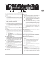
1
ULTRABASS BVT4500H/5500H
User manual
Version 1.1 2007-07
ULTRABASS BVT4500H/5500H
IMPORTANT SAFETY INSTRUCTIONS
CAUTION:
To reduce the risk of electric shock, do not remove
the top cover (or the rear section). No user
serviceable parts inside; refer servicing to qualified
personnel.
WARNING:
To reduce the risk of fire or electric shock, do not
expose this appliance to rain and moisture. The
apparatus shall not be exposed to dripping or
splashing and no objects filled with liquids, such
as vases, shall be placed on the apparatus.
CAUTION:
Before changing the fuse, switch off the device
and pull the plug to avoid electric shock or damage
to the device.
This symbol, wherever it appears, alerts you to the
presence of uninsulated dangerous voltage inside
the enclosure—voltage that may be sufficient to
constitute a risk of shock.
This symbol, wherever it appears, alerts you to
important operating and maintenance instructions
in the accompanying literature. Please read the
manual.
2
ULTRABASS BVT4500H/5500H
Foreword
Dear customer,
Welcome to the team of
ULTRABASS users and
thank you very much for
expressing your confidence in BEHRINGER
products by purchasing the
BEHRINGER BVT4500H/
BVT5500H.
Writing this foreword for
you gives me great
pleasure, because it
represents the culmination
of many months of hard
work delivered by our
engineering team to
achieve a very ambitious
goal: to present an
outstanding
bass
workstation that gives you
maximum flexibility and performance with its unique sound
character and broad range of functions.
The task of designing our new BVT4500H/5500H certainly meant
a great deal of responsibility, which we assumed by focusing
on you, the discerning user and musician. Meeting your
expectations also meant a lot of work and night shifts. But it was
fun, too. Developing a product usually brings a lot of people
together. What a great feeling it is when all who participated in
such a project can be proud of what they’ve achieved.
It is our philosophy to share our enjoyment with you, because
you are the most important member of the BEHRINGER team.
With your highly competent suggestions for new products you’ve
made a significant contribution to shaping our company and making
it successful. In return, we guarantee you uncompromising quality
as well as excellent technical and audio properties at an extremely
reasonable price. All of this will enable you to give free rein to
your creativity without being hampered by budget constraints.
3
ULTRABASS BVT4500H/5500H
1. Introduction
With the BVT4500H/5500H you have acquired a pro-level amplifier
from our ULTRABASS series. This classic bass amp combines
an uncompromising, “cutting-through” sound with a full range of
sound-shaping features.
CAUTION: The following applies only to BVT versions that can
be switched between 120 V and 230 V: The fuse holder on the
mains connector has 3 triangular markings, with two of these
triangles opposing each other. The BVT4500H/5500H is set to
the operating voltage printed next to these markers and can be
set to another voltage by turning the fuse holder by 180°.
1.1 The Design Concept
Over the past few years, flexibility has become important. Bass
players must now offer a broad range of sounds and play in
different venues: home studios, professional studios, and live
concerts. Additionally, the world of electric bass playing has
changed. New effects devices and basses, with five or six
strings, are launched all the time. There is also the desire to
create one’s own, “unique” sound—which can only be achieved
with innovative amplifiers.
In response to these dual needs (flexibility and individuality), the
BVT4500H/5500H offers you:
V
TONE and GRAPHIC EQ features—for shaping and refining
sound.
V
VTC (Virtual Tube Circuitry)—adding the warmth of vintage
tube circuitry to sound.
V
Jacks for connecting the BVT4500H/5500H to effects
processors, mixers/recording units, other preamps, and
other power amps.
V
If the unit is damaged, please do NOT return it to us;
instead, notify your dealer and the shipping
company immediately, otherwise claims for damage
or replacement may not be granted.
Please always use the original packaging to avoid
damage due to storage or shipping.
Never let unsupervised children play with the
BVT4500H/5500H or with its packaging.
Recycle whenever possible.
1.2.2 Initial operation
Before changing the fuse, switch off the device and
pull the plug to avoid electric shock or damage to
the device.
Please make sure that all units have a proper earth
connection. For your own safety, never remove or
disable the earth conductor from the unit or of the
AC power cord.
IMPORTANT NOTES CONCERNING INSTALLATION
Your BVT4500H/5500H was carefully packed at the factory,
and the packaging was designed to protect the unit from damage
caused by rough handling. Nevertheless, we recommend that
you carefully examine the packaging and its contents for any
signs of physical damage that may have occurred during transit.
Blown fuses must be replaced by fuses of the same
type
and
rating!
Please
refer
to
the
“SPECIFICATIONS” for details.
The BVT4500H/5500H power connection is made by using the
enclosed cable and the amplifier’s standard IEC receptacle. It
meets all of the international safety certification requirements.
1.2.1 Shipment
If you set the unit to a different mains voltage, be
sure to use a fuse of the correct type and rating.
Please refer to the “SPECIFICATIONS” for details.
CAUTION!
2 types of speaker jacks: ¼" TS and compatible with Neutrik
Speakon connectors.
1.2 Before you get started
Please note that when operating the unit at 120 V, a
higher fuse rating is required. Please refer to the
“SPECIFICATIONS” for details.
Ensure adequate air supply and to avoid overheating
do not place the unit near radiators etc.
Before you connect your BVT4500H/5500H to the mains, please
make sure that your local voltage matches the voltage required
by the unit.
The sound quality may diminish within the range of
powerful broadcasting stations and high-frequency
sources. Increase the distance between the
transmitter and the device and use shielded cables
for all connections.
1.2.3 Online registration
Please do remember to register your new BEHRINGER equipment
right after your purchase by visiting www.behringer.com
(alternatively www.behringer.de) and kindly read the terms and
conditions of our warranty carefully.
Should your BEHRINGER product malfunction, our goal is to have
it repaired as quickly as possible. To arrange for warranty service,
please contact the retailer from whom the equipment was
purchased. Should your BEHRINGER dealer not be located in
your vicinity, you may directly contact one of our subsidiaries.
Corresponding contact information is included in the original
equipment packaging (Global Contact Information/European
Contact Information). Should your country not be listed, please
contact the distributor nearest you. A list of distributors can be
found in the support area of our website (www.behringer.com).
Registering your purchase and equipment with us helps us
process your repair claims quicker and more efficiently.
Thank you for your cooperation!
2. Front panel
4
ULTRABASS BVT4500H/5500H
Fig. 2.2: BVT5500H front panel
This section describes how to use the front panel of the
BVT4500H and the BVT5500H, illustrated on the previous page
and above.
( 9 ) PEAK LED:
At various points in the signal path, the BVT monitors the
level of the audio signal. When the level is too high, the
PEAK LED warns that clipping can occur. If the LED:
( 1 ) POWER switch:
Use the POWER switch to turn on your BVT4500H/5500H.
The POWER switch should always be in the “Off” position
when you are about to connect your unit to the wall socket
or disconnect it.
Switch-on thumps can damage your hearing and
your speakers. Before you connect the BVT to the
mains, ensure that it is turned off.
V
occasionally illuminates, the BVT clips only some
peaks in the audio signal. Occasional clipping does
not reduce the sound quality and shows that the
signal is strong enough.
V
never illuminates, the BVT does not clip any signal
peaks in the audio signal. The audio signal is probably
too weak to make use of the full dynamic range.
Increase the GAIN ( 8 ) setting until the PEAK LED
lights up only occasionally, at the strongest signal
peaks.
V
constantly illuminates, the BVT clips a large part of
the audio signal and you will hear a distortion. Lower
the GAIN setting and check for extreme fader or
control settings.
( 2 ) VTC LED:
When the BVT is off, this LED is not illuminated. When it is
on, this LED is illuminated and indicates that the amp is
activated for use. VTC is BEHRINGER’s analog technology
that emulates the warmth of vintage tube circuitry.
INPUT features
To input an audio signal to the BVT, use features ( 3 ) - ( 7 ),
as follows:
( 3 ) 0 dB jack:
To connect an electric bass to the BVT, use this ¼" mono
jack (unbalanced). Basses with active pickups create highlevel signals. If your bass includes an active pickup and
you work with:
V
V
the BVT4500H, use the PAD button ( 4 ) to reduce the
input audio signal.
the BVT5500H, use the -15 dB jack ( 5 )instead of
the 0 dB jack.
TONE features
“Tone” refers to the presence and quality of these frequency
bands of an audio signal:
V
bass: from 30 to 200 Hz
V
mid-range: from 200 to 2 000 Hz
V
treble: from 2 000 Hz to 20 kHz
The BVT offers controls to effectively tailor the sounds to your
needs by cutting or boosting specific bands. To adjust the tone,
use features (10) - (13), as follows:
(10) VOICING control (BVT5500H only):
( 4 ) PAD button (BVT4500H only):
If the PEAK LED ( 9 ) constantly illuminates and the GAIN
control ( 8 ) is set to 0 (zero), the input level of the audio
signal is too high. In this case, press this button to activate
the pad. The pad reduces the input sensitivity by 15 dB.
( 5 ) -15 dB jack (BVT5500H only):
To connect an active bass to the BVT5500H, use this
¼" mono jack (unbalanced). Using this jack will give you a
lower input sensitivity as compared with the 0 dB jack.
( 6 ) MUTE button (BVT5500H only):
Use this button if you want to tune a bass without hearing
the tone. This feature mutes the main signal path, but not
the TUNER output.
( 7 ) OVERDRIVE button (BVT5500H only):
Use this button to add a distorted texture to the audio signal.
This feature “overdrives” the BVT5500H preamp.
( 8 ) GAIN control:
Use this control to boost or cut the level of the input signal.
To select the tone you want, turn this knob to one of the
following presets. The BVT5500H equalizes the audio signal
for you.
1:
Prominent bass and treble tones (scooped mids).
2:
Smooth and warm treble tones (passive tone).
3:
Flat, natural bass tones (no equalization).
4:
Bright treble tones.
5:
Flat, natural bass tones that are not muddy (bass
rolloff).
(11) - (13) BASS, MID, and TREBLE controls:
For each tone (bass, mid-range, and treble) that you can
emphasize or de-emphasize, the BVT includes a single
TONE control.
To emphasize a tone, you can turn the relevant tone control
toward 10 (maximum boost). Alternatively, you might
consider lowering adjacent bands. To de-emphasize a tone,
you can turn the relevant tone control toward 0
(maximum cut).
2. Front panel
5
ULTRABASS BVT4500H/5500H
When you choose to cut rather than boost an audio
signal, you protect audio equipment from high
signal levels (clipping) and preserve valuable
headroom.
(17) EFFECTS MIX control (BVT5500H only):
If you created an effects loop, use this control to adjust the
dry-wet mix. As you turn this control toward:
V
0 (zero), you hear more of the dry signal (without
effects). At zero, you hear only the dry signal.
V
10, you hear more of the wet signal (effects). At 10,
you hear only the wet signal.
GRAPHIC EQ features
With the TONE controls ((10) - (13)) discussed above, you
emphasize and de-emphasize three fairly wide frequency bands.
However, with the GRAPHIC EQ features, you can emphasize
and de-emphasize 9 more narrow frequency bands. This lets
you refine the sound that you created with the TONE controls.
The GRAPHIC EQ features include (14)-(16):
MASTER features
(14) EQ ON button:
(18) MASTER control:
For details about creating an effects loop, see 3. REAR
PANEL ((29) - (30)).
To turn graphic EQ and level features, push this button.
To adjust the speaker volume and the level of the PREAMP
OUTPUT, turn this control toward 0 (no volume/level) or,
alternatively 10 (maximum volume/level).
(15) EQ faders:
If you activated the frequency-band faders (14), you can
use each one to emphasize and de-emphasize a specific
frequency band. The center frequency of each frequency
band is displayed directly above the relevant fader.
(19) LIMITER button:
The limiter reduces only the signal peaks that can overdrive
the POWER AMP and distort the audio signal. The limiter
prevents the BVT4500H/5500H from clipping these signal
peaks. To activate or alternatively deactivate the limiter,
push this button.
To emphasize (boost) a frequency band, slide the relevant
fader up. Alternatively, slide the faders for the surrounding
frequency bands down.
To de-emphasize (cut) a frequency band, slide the relevant
fader down. Alternatively, slide the faders for the
surrounding frequency bands up.
Cutting rather than boosting a frequency band
protects audio equipment from high signal levels
(clipping) and preserves valuable headroom.
Because high signal peaks can damage
loudspeakers, it is recommended to activate the
limiter and not to play at full volume for a long time
without ear protection.
(20) LIMIT LED:
When the limiter is activated, this LED is illuminated.
(16) LEVEL fader (BVT5500H only):
To compensate possible level changes of the equalized
signal, slide this control between +12 and -12. At “0” level,
the BVT5500H neither boosts nor cuts the equalized signal.
3. Rear panel
6
ULTRABASS BVT4500H/5500H
If you use a single speaker or a high-power speaker, connect
this speaker to the Neutrik Speakon compatible jack. To prevent
electrical shock and ensure the correct polarity, this jack locks
an audio plug in place.
Before you connect speakers to the BVT4500H/5500H,
turn it off.
alternatively to a recording unit, use this XLR jack
(balanced).
Before you connect the BVT4500H/5500H to mic input
on a mixer, turn off the phantom power on the
relevant channel of the mixer.
(35) TUNER OUT jack:
To connect the BVT4500H/5500H to an electronic tuner,
use this ¼" TS jack.
Your speaker cabinets should have a sufficient
power rating (BVT4500H: > 450 W, BVT5500H: > 550 W)
and preferably a total impedance of 4 Ω or higher.
Too high a load impedance will decrease the output
power rating of the power stage. For details, refer
to the chapter “ABOUT SPEAKER IMPEDANCE”.
To tune while muting the PARALLEL SPEAKER OUTPUTs,
do one of the following. If you work with:
V
(27) POWER AMP INPUT:
To connect an external preamplifier to the BVT, use this
¼" TS jack.
(28) PREAMP OUTPUT:
the BVT4500H, turn the MASTER control to 0
(minimum setting).
Alternatively, you can use the tuner’s mute feature:
Connect EFFECTS SEND (30) to the tuner input and
EFFECTS RETURN (29) to the tuner output. When
you:
V
activate the mute feature on the tuner, the tuner
does not send the audio signal to the RETURN
jack.
V
deactivate the mute feature on the tuner, the
tuner sends the audio signal to the RETURN
jack. The audio signal follows the signal path to
the PARALLEL SPEAKER OUTPUTs.
To connect an external power amplifier to the BVT, use
this ¼" TS jack.
EFFECTS LOOP jacks
To connect the BVT4500H/5500H to an effects processor you
can use one or, alternatively both of these jacks ((29)- (30)).
Keep in mind that the BVT4500H and the BVT5500H do not process
effects in the same way. For details, see “THE SIGNAL PATH”.
V
(29) RETURN jack:
To send an audio signal from an effects processor to the
BVT, use this ¼" TS jack.
(30) SEND jack:
To send an audio signal from the BVT to an effects
processor, use this ¼" TS jack.
the BVT5500H, activate the mute feature ( 6 ).
4. About speaker impedance
The total impedance of the speakers that you connect to the BVT
affects the power output of the BVT. The minimum speaker
impedance is 4 Ω. When the total load is 4 Ω, the BVT supplies
the optimal power.
How to calculate the speaker impedance
LINE OUTPUT features
To send an audio signal from the BVT to a mixer or a recording
unit, use the LINE OUTPUT features ((31) - (34)), as follows:
(31) LEVEL control:
When using more than one speaker and each connecting to
another BVT speaker jack, the speakers are connected in parallel.
To calculate the resulting total impedance of the speakers, use
the following formula—
To adjust the level of any LINE OUTPUT, turn this knob
toward min (no level) or, alternatively max. The value of
the max setting depends on what you selected via the
PRE/POST button (33). If you selected:
V
PRE: max is ~ 0 dB.
—where Z1, Z2 etc. are each the impedance of a single speaker
and Ztotal is the resulting impedance of all speakers.
V
POST: max is ~ 10 dB.
For two speakers (Z1 and Z2), the formula reads as:
(32) GND LIFT button:
Z total =
To manage the ground connection between the BVT and a
mixer/recording unit, use this button. When this button is:
V
V
Z1 ⋅ Z 2
Z1 + Z 2
pushed out, you maintain a ground connection that
prevents electrostatic charges from interfering with
an audio signal.
Via the formula, you get a 4 Ω load with:
V
one 4 Ω speaker
pushed in, you break the ground connection. Do this
only when ground-loop hum interferes with an audio
signal.
V
two 8 Ω speakers
V
one 8 Ω speaker and two 16 Ω speakers
(33) PRE/POST button:
To select the type of signal you want to send to a
mixer/recording unit, use this button. When this button is:
V
pushed out (PRE EQ and effects), the BVT does not
apply any preamp features (TONE/EQ/EFFECTS) to
the audio signal.
V
pushed in (POST EQ and effects), the BVT applies all
preamp features to the audio signal.
As the speaker impedance decreases, the output
power of the BVT increases. High output power
can damage your speakers. As the speaker
impedance increases, the output power of the BVT
decreases.
For details, see “THE SIGNAL PATH”.
(34) BALANCED OUTPUT:
To connect the BVT to the mic input on a mixer or,
4. About speaker impedance
7
ULTRABASS BVT4500H/5500H
5. Setup example
The following illustration provides an example of how to set up
the BVT5500H.
8
ULTRABASS BVT4500H/5500H
7. Audio connectors
6.4 EFFECTS LOOP
The EFFECTS LOOP section can be used in three ways:
6.4.1 SEND and RETURN
V
PURPOSE: To create an effects loop, i.e., to apply external
effects to the signal.
V
RESULTS:If you use the:
V
BVT4500H, only the audio signal that enters via the
RETURN jack continues to follow the BVT4500H
signal path. The level of the effects has to be adjusted
on the external unit.
V
BVT5500H, both the main audio signal and the audio
signal that enters via the RETURN jack follow the
BVT5500H signal path. To adjust the dry-wet mix,
use the EFFECTS MIX control.
This section illustrates the audio connectors that you need for
the BVT jacks. For details about most BVT jacks, see
the section “REAR PANEL”. For details about the INPUT jack, see
the section “FRONT PANEL”.
6.4.2 SEND only (BVT5500H only)
V
PURPOSE: To send an audio signal from the BVT5500H to
an effects processor.
V
RESULTS: The main signal path is not affected.
Fig. 7.1: The connector for a ¼" TS jack
Speaker connector
(compatible with Neutrik Speakon connector)
6.4.3 RETURN only
V
PURPOSE: To send an audio signal from an external preamp to the BVT4500H/5500H, i.e., to use the BVT as a
power amp only.
V
RESULTS: If you use the:
V
BVT4500H, the INPUT jack is deactivated. The signal
path begins at the RETURN jack.
V
BVT5500H, the INPUT jack remains active. You could
e.g., connect two basses to the BVT, one to INPUT
and the other to RETURN. To adjust the balance
between the two, use the EFFECTS MIX control.
1+
1+
1-
1-
Fig. 7.2: The connector for a Neutrik Speakon compatible
jack
6.5 INSERT CHANNEL
6.5.1 PREAMP OUTPUT
V
PURPOSE: To process an audio signal with all BVT preamp
features (TONE, EQ, EFFECTS), and then send the audio
signal to an external power amp. The BVT settings affect
the volume on the external amp.
V
RESULTS: The main signal path is not affected.
6.5.2 POWER AMP IN
V
PURPOSE: To process an audio signal with an external
preamp, and then send the audio signal to the
BVT4500H/5500H power amp.
V
RESULTS: The signal path begins at the POWER AMP IN
jack. The signal is independent of the MASTER control.
Switch off the unit before connecting an external
preamp to POWER AMP IN.
7. Audio connectors
Fig. 7.3: The connector for an XLR jack
9
ULTRABASS BVT4500H/5500H
10. Warranty
§ 1 Other warranty rights and national law
1. This warranty does not exclude or limit the buyer’s statutory
rights provided by national law, in particular, any such rights against
the seller that arise from a legally effective purchase contract.
2. The warranty regulations mentioned herein are applicable unless
they constitute an infringement of national warranty law.
§ 2 Online registration
Please do remember to register your new BEHRINGER equipment
right after your purchase by visiting http://www.behringer.com and
kindly read the terms and conditions of our warranty carefully.
Registering your purchase and equipment with us helps us process
your repair claims quicker and more efficiently. Thank you for your
cooperation!
§ 3 Warranty
1. BEHRINGER (BEHRINGER International GmbH including all
BEHRINGER subsidiaries, except BEHRINGER Japan) warrants
the mechanical and electronic components of this product to be
free of defects in material and workmanship for a period of one (1)
year* from the original date of purchase, in accordance with the
warranty regulations described below. BEHRINGER warrants the
mechanical and electronic components of this product to be free
of defects in material and workmanship for a period of one (1)
year* from the original date of purchase, in accordance with the
warranty regulations described below. If the product shows any
defects within the specified warranty period that are not excluded
from this warranty as described under § 5, BEHRINGER shall, at its
discretion, either replace the product by providing a new or
reconditioned product or repair the product using suitable new or
reconditioned parts. In the case that other parts are used which
constitute an improvement, BEHRINGER may, at its discretion,
charge the customer for the additional cost of these parts. In case
BEHRINGER decides to replace the product, this warranty shall
apply to the replacement product for the remaining initial warranty
period, i.e one year* from the date of purchase of the initial product.
2. If the warranty claim proves to be justified, the product will be
returned to the user freight prepaid.
2. If the product needs to be modified or adapted in order to
comply with applicable technical or safety standards on a national
or local level, in any country which is not the country for which the
product was originally developed and manufactured, this
modification/adaptation shall not be considered a defect in
materials or workmanship. The warranty does not cover any such
modification/adaptation, irrespective of whether it was carried out
properly or not. Under the terms of this warranty, BEHRINGER shall
not be held responsible for any cost resulting from such a
modification/adaptation.
3. Free inspections and maintenance/repair work are expressly
excluded from this warranty, in particular, if caused by improper
handling of the product by the user. This also applies to defects
caused by normal wear and tear, in particular, of faders, crossfaders,
potentiometers, keys/buttons, tubes, guitar strings, illuminants and
similar parts.
4. Damage/defects caused by the following conditions are not
covered by this warranty:
V
improper handling, neglect or failure to operate the unit in
compliance with the instructions given in BEHRINGER user
or service manuals.
V
connection or operation of the unit in any way that does not
comply with the technical or safety regulations applicable in
the country where the product is used.
V
damage/defects caused by force majeure or any other
condition that is beyond the control of BEHRINGER.
5. Any repair or opening of the unit carried out by unauthorized
personnel (user included) will void the warranty.
6. If an inspection of the product by BEHRINGER shows that the
defect in question is not covered by the warranty, the inspection
costs are payable by the customer.
7. Products which do not meet the terms of this warranty will be
repaired exclusively at the buyer’s expense. BEHRINGER will inform
the buyer of any such circumstance. If the buyer fails to submit a
written repair order within 6 weeks after notification, BEHRINGER
will return the unit. Costs for freight and packing will be invoiced
separately C.O.D. When the buyer has sent in a written repair order
such costs will also be invoiced separately.
3. Warranty claims other than those indicated above are expressly
excluded.
§ 4 Return authorization number
1. To obtain warranty service, the buyer (or his authorized dealer)
must call BEHRINGER during normal business hours BEFORE
returning the product. To obtain warranty service, the buyer (or his
authorized dealer) must call BEHRINGER as exclusive distributor
of BEHRINGER products (see enclosed list) during normal business
hours BEFORE returning the product. All inquiries must be
accompanied by a description of the problem. The buyer or his
authorized dealer will receive a return authorization number.
2. Subsequently, the product must be returned in its original
shipping carton, together with the return authorization number.
The return shipment address will be indicated by BEHRINGER.
§ 6 Warranty transferability
This warranty is extended exclusively to the original buyer (customer
of retail dealer) and is not transferable to anyone who may
subsequently purchase this product. No other person (retail dealer,
etc.) shall be entitled to give any warranty promise on behalf of
BEHRINGER. No other person (retail dealer, etc.) shall be entitled
to give any warranty promise on behalf of either BEHRINGER or
BEHRINGER.
§ 7 Claim for damages
Failure of BEHRINGER to provide proper warranty service shall not
entitle the buyer to claim (consequential) damages. In no event
shall the liability of BEHRINGER exceed the invoiced value of the
product.
* Customers in the European Union please contact BEHRINGER
Germany Support for further details.
3. Shipments without freight prepaid will not be accepted.
§ 5 Warranty regulations
1. Warranty services will be furnished only if the product is
accompanied by a copy of the original retail dealer’s invoice. Any
product deemed eligible for repair or replacement under the terms
of this warranty will be repaired or replaced.
Technical specifications and appearance subject to change without notice. The information contained herein is correct at the time of
printing. All trademarks (except BEHRINGER, the BEHRINGER logo, JUST LISTEN and ULTRABASS) mentioned belong to their
respective owners and are not affiliated with BEHRINGER. BEHRINGER accepts no liability for any loss which may be suffered by
any person who relies either wholly or in part upon any description, photograph or statement contained herein. Colors and
specifications may vary slightly from product. Products are sold through our authorized dealers only. Distributors and dealers are not
agents of BEHRINGER and have absolutely no authority to bind BEHRINGER by any express or implied undertaking or representation.
No part of this manual may be reproduced or transmitted in any form or by any means, electronic or mechanical, including photocopying
and recording of any kind, for any purpose, without the express written permission of BEHRINGER International GmbH.
ALL RIGHTS RESERVED. © 2007 BEHRINGER International GmbH, Hanns-Martin-Schleyer-Str. 36-38, 47877 Willich-Münchheide II,
Germany. Tel. +49 2154 9206 0, Fax +49 2154 9206 4903
12
10. Warranty