1
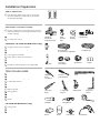
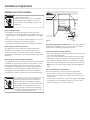
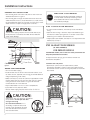
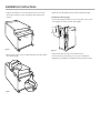
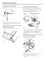
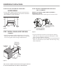
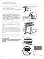
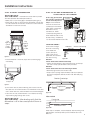
GE Consumer & Industrial
Appliances
Installation Instructions
If you have questions, call 800.626.2000 or visit our website at: www.monogram.com
Built-In Dishwashers
ZBD1850*
ZBD1870
*For ZBD1850 also refer to the
instructions provided on the template
packed with that model
Safety Information
STOP
BEFORE YOU BEGIN
Read these instructions completely and
carefully.
IMPORTANT – Observe all governing codes and
ordinances.
• Note to Installer – Be sure to leave these instructions for the
consumer’s and local inspector’s use.
• Note to Consumer – Keep these instructions with your
Owner’s Manual for future reference.
• Skill Level – Installation of this dishwasher requires
basic mechanical, electrical and plumbing skills. Proper
installation is the responsibility of the installer. Product
failure due to improper installation is not covered under
the GE Appliance Warranty. See warranty information.
• Completion Time – 1 to 3 Hours. New installations require
more time than replacement installations.
IMPORTANT – The dishwasher MUST
be installed to allow for future removal from the enclosure
if service is required.
If you received a damaged dishwasher, you should
immediately contact your dealer or builder.
Optional Accessories – See the Owner’s Manual for available
custom panel kits.
READ CAREFULLY.
KEEP THESE INSTRUCTIONS.
FOR YOUR SAFETY
Read and observe all CAUTIONS and WARNINGS shown
throughout these instructions.
While performing installations described in this booklet,
gloves and either safety glasses or goggles should be worn.
For Monogram local service in your area, 1.800.444.1845.
For Monogram service in Canada 1.888.880.3030.
For Monogram Parts and Accessories, call 1.800.626.2002.
CONTENTS
Installation Preparation
Parts Supplied ...................................................................................................3
Materials You Will Need ...............................................................................3
Tools You Will Need ........................................................................................3
Prepare Dishwasher Enclosure .................................................................4
Drain Requirements .......................................................................................4
Prepare Electrical Wiring .............................................................................5
Prepare Hot Water Line ................................................................................6
Installation Instructions
Step 1, Check Door Balance .......................................................................6
Step 1A, Adjust Door Springs .....................................................................6
Step 2, Adjust Leveling Legs .......................................................................8
Step 3, Remove Toekick ................................................................................8
Step 4, Install Power Cord ...........................................................................8
2
Step 5, Install 90° Elbow ...............................................................................8
Step 6, Position Water Line and House Wiring ..................................9
Step 7, Install Drain Hose Through Cabinet ........................................9
Step 8, Slide Dishwasher Partially Into Cabinet ................................9
Step 9, Position Dishwasher Under Countertop ............................10
Step 10, Level Dishwasher .......................................................................11
Step 11, Secure Dishwasher To Cabinet ............................................11
Step 12, Connect Water Supply ............................................................12
Step 13, Connect Drain Line ....................................................................12
Step 14, Connect Power Supply ............................................................13
Step 15, Pre-Test Checklist .......................................................................13
Step 16, Dishwasher Wet Test ................................................................14
Step 17, Replace Toekick ..........................................................................14
Step 18, Literature ........................................................................................14
Installation Preparation
PARTS SUPPLIED:
■ Two #8 Phillips head wood screws, 5/8" long to
secure dishwasher to underside of countertop
(in literature package).
2 Wood Screws
Wood
Wood
Screw
Screw
MATERIALS YOU WILL NEED:
■ Ferrule, compression nut and 90° Elbow (3/8" NPT
external thread on one end, opposite end sized to
fit water supply)
■ Thread seal tape
■ UL Listed wire nuts (3)
90° Elbow,
Ferrule and
Compression Nut
Materials For New Installations Only:
■
■
■
■
■
■
■
■
Air gap for drain hose, if required
Waste tee for house plumbing, if applicable
Electrical cable or power cord, if applicable
Screw type hose clamps
Strain relief for electrical connection
Hand shut-off valve
Water line 3/8" min. copper
Coupler for extending drain line, if applicable
Hand
Shut-Off
Valve
Thread
Seal Tape
Wire Nuts (3)
Hand ValveTape Wire Nuts
90 ϒElbow
Waste Tee
Electrical Cable
(or Power Cord, if applicable)
Hot Water Line
Waste Tee
Air
Gap
Hot Water Line
Screw Type
Hose Clamps
Strain Relief
Coupler
Strain Relief
TOOLS YOU WILL NEED:
■
■
■
■
■
■
■
■
■
■
■
Phillips head screwdriver
5/16" and 1/4" nutdriver
T25 torque driver (PDW__II only)
6" Adjustable wrench
Level
Carpenters square
Measuring tape
Safety glasses
Flashlight
Bucket to catch water when flushing the line
Gloves
For New Installations Only:
■ Tubing cutter
■ Drill and appropriate bits
■ Hole saw set
Electrical Cable
Air Gap Hose Clamps
Phillips
Head
Screwdriver
1/4" and
5/16" Nutdriver
Level
Level 2
Screw DriverNutdriver
II
T25 Torque
Driver
6" Adjustable
Wrench
Coupler
Tubing Cutter
Carpenters
Square
Tubing Cutter
Carpenters Square
Crescent Wrench
Flashlight
Measuring Tape
Safety Glasses
Measuring Tape
Flashlight Safety Glasses
Gloves
GLOVES
Bucket
Bucket
Hole Saw Set
Drill and Bits
Hole Saw Bit
Drill & Bits
3
Installation Preparation
PREPARE DISHWASHER ENCLOSURE
WARNING
This Wall Area
must be Free of
Pipes or wires
34-1/2" ± 1/2"
Underside of
Countertop
to Floor
5"
4"
To reduce the risk of electric shock, fire, or injury to persons, the
installer must ensure that the dishwasher is completely enclosed
at the time of installation.
24"
5" 4" Min.
Cabinets
Square
and
Plumb
6"
Figure A
• The dishwasher must be installed so that drain hose is no
more than 10’ in length for proper drainage.
17 5/8" Min.
18" Max.
Floor MUST
Plumbing and Electric Service
be Even with
Must Enter Shaded Area
Room Floor
CLEARANCES: When
installed into a corner,
allow 2” min. clearance
between dishwasher and
adjacent cabinet, wall or
other appliances. Allow
25-5/8" min. clearance
from the front of the
dishwasher for door
opening. Figure B
Dishwasher
25-5/8"
Clearance for Door
Opening 2" Minimum
• The rough cabinet opening must be at least 24" deep, 17-5/8"
to 18" wide and approximately 34-1/2" high from floor to
underside of the countertop.
2514A
Figure B
2514B
DRAIN REQUIREMENTS
• Follow local codes and ordinances.
• Do not exceed 10’ distance to drain.
• Do not connect drain lines from other devices to the
dishwasher drain hose.
NOTE: Air gap must be used if waste tee or disposer connection
is less than 18" above floor to prevent siphoning.
DETERMINE DRAIN METHOD
Figure C
Method 1 – Air Gap with Waste Tee or Disposer
An air gap must be used when required by local codes and ordinances.
The air gap must be installed according to manufacturer’s instructions.
���������
The type of drain installation depends on the following
questions.
■ Do local codes or ordinances require an air gap?
■ Is waste tee less than 18" above floor?
If the answer to either question is YES, Method 1 MUST
be used.
• If the answers are NO, either method may be used.
CABINET PREPARATION
���������
���
����
���
����
Figure D
• Drill a 1-1/2" diameter hole in the cabinet wall within
the shaded areas shown in Figure A for the drain hose
connection. The hole should be smooth with no sharp edges.
IMPORTANT: When connecting
drain line to disposer, check to be
������
������
sure that drain plug has been
����
removed. DISHWASHER WILL NOT
DRAIN IF PLUG IS LEFT IN PLACE.
4
Countertop
�������
Method 2 – Drain Hose Routing
When not using an air gap, the drain hose must be routed to form a high
loop of at least 32" to prevent siphoning. See Step 15 on page 10.
���������
���������
CAUTION:
An air gap MUST BE USED if the drain hose is connected to
waste tee or disposer lower than 18" above the floor level.
Failure to provide the proper drain connection height with an
air gap or 32" minimum high drain loop will result in improper
draining of the dishwasher, which may cause damage.
Installation Preparation
PREPARE ELECTRICAL WIRING
WARNING
FOR PERSONAL SAFETY:
Remove house fuse or open circuit breaker
before beginning installation. Do not use
an extension cord or adapter plug with this
appliance.
Electrical Requirements
• This appliance must be supplied with 120V, 60Hz., and
connected to an individual properly grounded branch circuit
protected
by a 15 or 20 ampere circuit breaker or time delay
#282 French
fuse.
• Wiring must be 2 wire with ground and rated for 75°C (176°F).
• If the electrical supply does not meet the above
requirements, call a licensed electrician before proceeding.
Grounding Instructions–Cable Direct
This appliance must be connected to a grounded metal,
permanent wiring system, or an equipment grounding
conductor must be run with the circuit conductors and be
connected to the equipment grounding terminal or lead on the
appliance.
Grounding Instructions–Power Cord Models
This appliance must be grounded. In the event of a malfunction
or breakdown, grounding will reduce the risk of electric shock
by providing a path of least resistance for electric current.
This appliance is equipped with a cord having an equipment
grounding conductor and a grounding plug. The plug must
be plugged into an appropriate outlet that is installed and
grounded in accordance with all local codes and ordinances.
WARNING The improper connection of the equipment
grounding conductor can result in electric
shock. Check with a qualified electrician or
service representative if you are in doubt that
the appliance is properly grounded. Do not
modify the plug provided with the appliance;
if it will not fit the outlet, have a proper outlet
installed by a qualified technician.
1-1/2” Dia.
Hole (Max.)
3”
from
Cabinet
24”
from Wall
Ground
Figure E
Black
White
For models equipped with power cord: Do not modify the plug
provided with the appliance; if it will not fit the outlet, have a
proper outlet installed by a qualified technician.
Cabinet Preparation and Wire Routing
• The wiring may enter the opening from either side, rear or the
floor within the shaded area.
• Cut a 1-1/2" max. diameter hole to admit the electrical cable.
Cable direct connections may pass through the same hole
as the drain hose and hot water line, if convenient. If cabinet
wall is metal, the hole edge must be covered with a bushing.
Note: Power cords with plug must pass through a separate
hole.
Electrical Connection to Dishwasher
Electrical connection is on the right front of dishwasher.
• For cable direct connections the cable must be routed as
shown in Figure E. Cable must extend a minimum of 24" from
the rear wall.
• For power cord connections, install a 3-prong grounding type
receptacle in the sink cabinet rear wall, 6" min. or 18" max.
from the opening, 6" to 18" above the floor.
#282 French
5
Installation Instructions
PREPARE HOT WATER LINE
• The line may enter from either side, rear or floor within the
shaded area shown in Figure F.
• The line may pass through the same hole as the electrical
cable and drain hose. Or, cut an additional 1-1/2" dia. hole to
accommodate the water line. If power cord with plug is used,
water line must not pass through power cord hole.
CAUTION:
The hot water supply line pressure must be at least 20 psi.
Lower pressures could cause the water valve to leak and
cause water damage.
Shut-off
Valve
1-1/2" Dia.
Hole
Hot
2"
From
Cabinet
Cabinet Face
18" From Wall
3" From Floor
Figure F
Water Line Connection
• Turn off the water supply.
• Install a hand shut-off valve in an accessible location, such
as under the sink. (Optional, but strongly recommended and
may be required by local codes.)
• Water connection is on the left side of the dishwasher. Install
the hot water inlet line, using no less than 3/8" O.D. copper
tubing. Route the line as shown in Figure F and extend
forward at least 18" from rear wall.
• Adjust water heater for 120°F to 150°F temperature.
• Flush water line to clean out debris.
• The hot water supply line pressure must be 20-120 PSI.
BEFORE YOU BEGIN
STOP
Locate and set aside the package containing
2 Phillips head countertop mounting screws
and 2 additional toekick screws (located in
the literature package).
STEP 1 CHECK DOOR BALANCE
• To check the door balance, hold the top of the dishwasher
firmly.
• Open the door slowly. If the door drops when released, you
will need to increase spring tension. If the door closes when
released, you will need to decrease tension.
• If adjustments are needed, see Step 1A. If no adjustments are
needed, skip to Step 2.
STEP 1A ADJUST DOOR SPRINGS
(IF NECESSARY)
FOR ZBD1870 MODELS
For ZBD1850 models, refer to the instruction provided on the
template packed with that model.
To adjust the door springs, you will need to remove the
dishwasher side panels.
To remove the side panels:
• Remove the screws from the top and back of each
dishwasher side panel, sixteen screws total. Open the door
and remove the four screws securing the panels to the inside
door frame.
Screws
Screws
Screws
Screws
CAUTION:
Opening the door will cause the dishwasher
to tip forward. Do not open the door
until you are ready
to install the dishwasher. If it is
necessary to open the door, hold
the top of the dishwasher securely
with one hand and hold the door
with the other hand.
6
Screws
Rear
Front
Figure G
Figure H
Installation Instructions
• Lay the dishwasher on its back. Remove the four screws
securing the toekick to the dishwasher, and remove the
toekick.
• Remove the side panels and set the dishwasher upright.
To adjust the door springs:
• Pull the spring adjustment pin out of the holes, insert in the
next highest or lowest hole and test again.
Increase
Screws
Decrease
Toekick
Figure I
Figure K
• Remove the single screw just above and to the side of each
front leveling leg.
• Adjust both door springs to the same tension.
• Continue moving the spring pin until door is balanced.
• Replace the dishwasher side panels and proceed to Step 2.
Screw
Screw
Figure J
7
Installation Instructions
STEP 2 ADJUST LEVELING LEGS
STEP 4 INSTALL POWER CORD
• Move the dishwasher close to the installation location and lay
it on its back.
Skip this step if dishwasher will be direct wired.
Use Power Cord Kit WX09X70910, available for purchase
from an authorized GE Appliance Dealer. The power cord and
connections must comply with the National Electrical Code,
Section 422 and/or local codes and ordinances.
• Maximum power cord length is 6'.
A
B Check That White, Black and
Green Dishwasher Wires Are Threaded
Thru Hole in Back
Remove
Junction Box
Cover
Adjust to
Installation
Height
White
Ground
Figure L
Black
D Use UL Listed
Wire Nuts
• Measure installation height and dishwasher height. Extend
leveling legs out from the dishwasher base, 1/2" less than
installation height.
STEP 3 REMOVE TOEKICK
• Remove the 4 toekick screws. Lift off the 2 piece toekick.
C
Insert Power
Cord Wires Thru
Strain Relief
and Tighten
Figure N
• Connect incoming power cord white (or ribbed) to dishwasher
white, black (or smooth) to black and ground to dishwasher
green wire. Use UL listed wire nuts of appropriate size.
• Replace junction box cover. Be sure wires are not pinched
under the cover.
Remove
4 Toekick
Screws
STEP 5 INSTALL 90° ELBOW
• Wrap 90° elbow with thread seal tape.
• Install a 90° elbow onto the water valve.
Fill
Hose
Figure M
90°
Elbow
Water
Valve
Bracket
Figure O
8
Thread
Seal Tape
• Do not over tighten 90° elbow, water valve bracket could
bend or water valve fitting could break.
• Position the end of the elbow to face the rear of the
dishwasher.
Installation Instructions
STEP 6 POSITION WATER LINE AND
HOUSE WIRING
STEP 8 SLIDE DISHWASHER PARTIALLY
INTO CABINET
• Position water supply line and house wiring on the floor of
the opening to avoid interference with base of dishwasher
and components under dishwasher.
DO NOT PUSH AGAINST FRONT PANEL WITH KNEES.
DAMAGE WILL OCCUR.
• Slide dishwasher into the opening a few inches at a time.
4"
6"
House
Water Wiring
Line
Do Not Push Against
Front Door Panel With
Knee. Damage to The
Door Panel Will Occur.
Figure P
STEP 7 INSTALL DRAIN HOSE THROUGH
CABINET
• Stand the dishwasher upright and position in front of the
opening. Insert drain hose into cabinet wall hole. If a power
cord is used, guide the end through a separate hole.
Insulation
Blanket
Maximum
Drain Hose
Length 10”
Reposition Dishwasher
by Grasping Both Sides
With Hands.
Figure R
• As you proceed, pull the drain hose through the opening
under the sink. Stop pushing when the dishwasher is a few
inches forward of adjacent cabinetry.
• Make sure drain hose is not kinked under the dishwasher and
there is no interference with the water line and wiring or any
other component.
Water
Line
Drain
Hose
House
Wiring
Power Cord
(If Used)
Figure Q
TIP: Position water line and house wiring on the floor
to avoid interference with base of dishwasher.
9
Installation Instructions
STEP 9 POSITION DISHWASHER UNDER
COUNTERTOP
• Push the dishwasher into the cabinet.
• Push the sides with your hands. Do not use your knee against
the door since door damage will occur.
• Check that the tub insulation blanket does not get
“bunched-up” or interfere with the springs as you slide it
into the cabinet.
• Center the dishwasher in the opening.
• Front of door panel should be flush with face of cabinet.
• Carefully open and close the door to ensure that the door
panel does not catch or rub on the cabinet frame.
• If the door catches or rubs on the frame, reposition and/or
level the unit (see Step 10) until the door moves freely and
does not contact the cabinet frame.
���������������������
����������������
����������������
���������
�������������������
���������������������
�������������������
������������������������
Figure S
The controls on these models are designed to be hidden by
your countertop. Align the dishwasher as shown in Figure
T. Leave a 1/2" minimum gap between the underside of the
countertop and the top of the dishwasher door as shown in
Figure W.
Note: If the drain hose gets trapped behind the unit it can
prevent the controls from being hidden by the countertop.
Note: If this dishwasher is replacing an existing dishwasher, the
old countertop bracket screw holes may not be in the correct
position to accept a top-control model. New holes may be
required.
Tip: The leveling legs can be used to increase or decrease
the amount of gap between the controls and the countertop
affecting the visibility of the controls.
���������
����
��������
������
����
������
�������
�����
������������
����������������
���������
���������
�������
���������
Figure T
Top View
IMPORTANT – Leave a 1/2" minimum gap between
���������
the controls and the underside of the countertop to prevent
condensation and damage to the control panel from
screwheads.
ON
OFF
DELAY
START
1 - 24 HRS.
LOW RINSE AID
Controls Hidden
by Countertop
Figure U
Countertop
Countertop
1/2”
Min.
Control
Panel
10
Dishwasher
Door
Figure V
Figure S
Figure W
Installation Instructions
STEP 10 LEVEL DISHWASHER
IMPORTANT – Dishwasher must be level for proper
dish rack operation and wash performance.
• Make sure 1/2" minimum gap is maintained (see Figure T).
• Place level on door to check that the dishwasher is level sideto-side. Place level on rack track inside tub to check that the
dishwasher is level front-to-back.
���
���������
�����
������
�������
���
��������
�����
�����
�������
Figure X
• If the dishwasher is not level, adjust the four leveling legs
individually.
�������
STEP 11 SECURE DISHWASHER TO
COUNTERTOP OR CABINET
In this step you will need Side-Mounting
Bracket
the 2 Phillips special head
screws set aside prior to
Step 1. The dishwasher
Countertop
must be secured to the
Mounting
brackets
countertop or the cabinet
sides. When countertops
Figure Z
are made of wood,
use Method 1. When
countertops are granite or
other materials that will not
accept screws, use Method
2 to secure dishwasher at the sides.
IMPORTANT –
Figure AA
Drive screws straight
�������� ����������������
and flush. Protruding
screw heads will
scratch the top or
sides of the control
panel and can interfere
with door closing.
Figure BB
Method 1
Secure dishwasher to wood countertop
• Fasten the dishwasher to the underside of the countertop
with the 2 Phillips special head screws provided.
Method 2
Secure dishwasher with side-mounting brackets
• Remove plug buttons (one on each side).
• Install screws through the dishwasher side mount bracket
and into the adjacent cabinet on each side. Reinstall plug
buttons.
��������
Granite Countertop
Turn Legs
to Adjust
Figure Y
Tip: Pull lower rack out, about halfway. Check to be sure the
rack does not roll forward or back into dishwasher. If the rack
rolls in either direction, the dishwasher must be leveled again.
• If door hits the tub, the dishwasher is not installed correctly.
Adjust leveling legs to align door to tub.
IMPORTANT – After leveling, verify that the
dishwasher is still in the correct position shown in
Step 9.
Plug Buttons
Screws
Figure CC
Either Method
2514C
����������
����
����
���������������
Figure DD
When step is complete, close dishwasher door and verify that
gap between countertop and top of dishwasher door is at
least 1/2".
11
�������
Installation Instructions
STEP 12 CONNECT WATER SUPPLY
DRAIN LINE INSTALLATION
Connect water supply line to 90° elbow.
• Slide compression nut,
then ferrule over end of
Compression Nut
water line.
Ferrule
• Insert water line into 90°
elbow.
• Slide ferrule against
Hot Water
elbow and secure with
90° Elbow Supply Line
compression nut.
• Connect drain line to air gap, waste tee or disposer using
either previously determined method.
Figure EE
Method 1 – Air gap with waste tee or disposer
Insert the drain hose to air gap as shown.
Waste Tee Installation
IMPORTANT – Check to be sure that door spring does
not rub or contact the fill hose or water supply line. Test by
opening and closing the door. Re-route the lines if a rubbing
noise or interference occurs.
Figure HH
�������
Method 2 – Drain Hose Routing
Disposer Installation
�������
Route the drain hose of the dishwasher to a minimum height of 32" from
Fasten drain hose at least at
drain
at least
at as shown.
theFasten
floor with
thehose
supplied
hanger
32" height with hanger supplied
32" height with hanger supplied
STEP 13 CONNECT DRAIN LINE
FOLLOW ALL LOCAL CODES AND ORDINANCES.
The molded end of the drain hose will fit 5/8" through 1"
diameter inlet ports on the air gap, waste tee or disposer.
• Determine size of inlet port
• Cut drain hose connector on the marked line, if required, to fit
the inlet port.
18"
Min.
Waste Tee Installation
Figure II
Cutting Lines
32"
Min.
05A-1183FF
32"
18" Min.
Min.
Disposer Installation
05A-1183GG
IMPORTANT – Either one of the above methods
1"
Figure FF
3/4"
5/8"
IMPORTANT: Do not cut corrugated
portion of hose
• If a longer drain hose is required, add up to 42" of length for
a total of 10' to the factory installed hose. Use 5/8" or 7/8"
inside diameter hose and a coupler to 9
connect the two
hose ends.
Secure the
connection with
����������
hose clamps.
�������
Figure GG
����������
• Secure the drain hose to the air gap, waste tee or disposer
with clamps.
����������
Note: TOTAL DRAIN HOSE LENGTH MUST NOT EXCEED 10' FOR
PROPER DRAIN OPERATION.
12
must be used or dishwasher will not operate properly.
IMPORTANT – When connecting
drain line to disposer, check to be sure
that drain plug has been removed.
DISHWASHER WILL NOT DRAIN IF
PLUG IS LEFT IN PLACE.
������
������
����
Tip: Avoid unnecessary service call charges. Always be sure
disposer drain plug has been removed before attaching
dishwasher drain hose to the disposer.
�������
Installation Instructions
STEP 14 CONNECT POWER SUPPLY
STEP 15 PRETEST CHECK LIST
Skip this step if equipped with power cord.
Verify that power is turned off at the source.
• Remove junction box cover “A”.
• Locate the three dishwasher wires, (white, black and green)
with stripped ends. Insert dishwasher wires through the small
hole in the junction box “B”.
• Secure house wiring to the bottom of the junction box with a
strain relief “C”.
• Use wire nuts to connect incoming ground to green, white to
white and black to black “D”.
• Replace junction box cover “E”. Check to be sure that wires
are not pinched under the cover.
Review this list after installing your dishwasher to avoid
charges for a service call that is not covered by your
warranty.
A
B Check That White, Black and
Green Dishwasher Wires Are Threaded
Thru Hole in Back
Remove
Junction Box
Cover
White
Ground
Black
■ Open door and remove all foam and paper packaging.
■ Locate the Owner’s Manual in the literature package.
■ Read the Owner’s Manual for operating instructions.
■ Check door opening and closing. If door does not open and
close freely or tends to fall, check spring adjustments. See
Step 1.
■ Check to be sure that wiring is secure under the dishwasher,
not pinched or in contact with door springs or other
components. See Step 9.
■ Check door alignment with tub. If door hits tub, level
dishwasher. See Step 10.
■ Pull lower rack out, about half way. Check to be sure it does
not roll back or forward on the door. If the rack moves,
adjust leveling legs. See Step 10.
D Use UL Listed
Wire Nuts
Figure JJ
WARNING
■ Check to be sure power is OFF.
C
■ Check door alignment with cabinet. If door hits cabinet,
reposition or relevel dishwasher. See Step 10.
Insert Power
Cord Wires Thru
Strain Relief
and Tighten
■ Verify water supply and drain lines are not kinked or in
contact with other components. Contact with motor or
dishwasher frame could cause noise. See Step 8.
If house wiring is not 2-wire with ground, a
ground must be provided by the installer.
When house wiring is aluminum, be sure to
use UL Listed anti-oxidant compound and
aluminum-to-copper connectors
■ Turn on the sink hot water faucet and verify water
temperature. Incoming water temperature must
be between 120°F and 150°F. A minimum of 120°F
temperature is required for best wash performance. See
“Prepare Hot Water Line,” page 5.
■ Add 2 quarts of water to the bottom of the dishwasher to
lubricate the pump seal.
■ Turn on water supply. Check for leaks. Tighten connections
if needed.
■ Remove protective film if present from the control panel
and door.
■ Avoid service call charges by ensuring there is an air gap
or drain hose routed through the required 32" minimum
height.
#282 French
11
13
Installation Instructions
STEP 16 DISHWASHER WET TEST
STEP 17 REPLACE TOEKICK
■ Turn on power supply (or plug power cord into outlet,
if equipped).
■ Start the unit to check for leaks.
– Press ON/OFF button to turn unit on
– Press CYCLE SELECT button until light below RINSE cycle
illuminates
■ Close door.
■ Check to be sure that water enters the dishwasher. If water
does not enter the dishwasher, check to be sure that water
and power are turned on.
Use Top 4
Screw Holes
■ Check for leaks under the dishwasher. If a leak is found, turn
off power supply, then tighten connections. Restore power
after leak is corrected.
■ Check for leaks around the door. A leak around the door
could be caused by door rubbing or hitting against
adjacent cabinet. Reposition the dishwasher if necessary.
See Step 9.
■ The dishwasher will drain and turn off about 5 to 7 minutes
after the first fill. Check drain lines. If leaks are found,
turn power off at the breaker and correct plumbing as
necessary. Restore power after corrections are made. See
Step 12.
■ Open dishwasher door and make sure most of the water
has drained. If not, check that disposer plug has been
removed and/or air gap is not plugged. See Step 13. Also
check drain line for kinking.
■ Run the dishwasher through another fill and drain cycle.
Check for leaks and correct if required.
■ At the end of drain, open door and press ON/OFF button to
turn unit off.
2-Piece To
ekick
Adjust Up
or Down
Figure KK
• Place 2-piece toekick against the legs of the dishwasher.
• Place the inner toekick piece (with slots) against the toekick
bracket. The slots should align with toekick bracket screw
holes. Allow the toekick to touch the floor.
• Place larger toekick over the inner piece and install 4 toekick
screws.
• Use additional 2 screws for installations over 33-1/2" high.
• Use both toekick pieces for all installation heights.
STEP 18 LITERATURE
• Be sure to leave complete literature package and Installation
Instructions with the consumer.
SPECIFICATIONS SUBJECT TO CHANGE WITHOUT NOTICE
GE Consumer & Industrial
General Electric Company
Louisville, Kentucky 40225
monogram.com
© 2005 General Electric Company
Pub. No. 31-30243
Dwg. No. 206C1559P181
ND 08C-2515 (4/08)