1
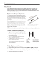
Emerge® EMS
Installer/User Guide
INSTRUCTIONS
This symbol is intended to alert the user to the presence of important operating and
maintenance (servicing) instructions in the literature accompanying the appliance.
Emerge® EMS
Installer/User Guide
Avocent, the Avocent logo, The Power of Being There and Emerge are registered
trademarks of Avocent Corporation. All other marks are the property of their
respective owners.
© 2005 Avocent Corporation. All rights reserved.
European approvals
European EMC directive 89/336/EEC
This equipment has been tested and found to comply with the limits for a class
A computing device in accordance with the specifications in the European
standard EN55022. These limits are designed to provide reasonable protection
against harmful interference. This equipment generates, uses and can radiate
radio frequency energy and if not installed and used in accordance with the
instructions may cause harmful interference to radio or television reception. However, there is no
guarantee that harmful interference will not occur in a particular installation. If this equipment
does cause interference to radio or television reception, which can be determined by turning the
equipment on and off, the user is encouraged to correct the interference with one or more of the
following measures: (a) Reorient or relocate the receiving antenna. (b) Increase the separation
between the equipment and the receiver. (c) Connect the equipment to an outlet on a circuit
different from that to which the receiver is connected. (d) Consult the supplier or an experienced
radio/TV technician for help.
iii
TA B L E O F C O N T E N T S
List of Figures ..................................................................................................................v
Chapter 1: Product Overview..........................................................................................1
Features and Benefits ........................................................................................................................ 1
Configuration Possibilities ................................................................................................................ 1
Further Expansion ............................................................................................................................ 3
Safety Precautions............................................................................................................................. 4
Chapter 2: Installation .....................................................................................................5
Locations ........................................................................................................................................... 5
Mounting ........................................................................................................................................... 6
Making Standard Connections .......................................................................................................... 8
Connections at the Transmitter ......................................................................................................... 8
Connections at the Receiver............................................................................................................ 13
Making Cascade Connections......................................................................................................... 16
Chapter 3: Operations ...................................................................................................23
Indicators ........................................................................................................................................ 23
Adjustments ..................................................................................................................................... 24
Brightness and Sharpness Adjustments........................................................................................... 24
Skew Compensation Adjustments (Emerge EMS1000MP-R Receivers Only)................................. 25
Appendices.....................................................................................................................29
Appendix A: Technical Support ....................................................................................................... 29
Appendix B: Troubleshooting.......................................................................................................... 30
Index................................................................................................................................31
iv
Emerge EMS Installer/User Guide
v
LIST OF FIGURES
Figure 1.1: A standard Emerge EMS1000P configuration driving two display/speakers sets.......... 1
Figure 1.2: A typical Emerge EMS1000MP configuration driving up to eight displays................... 2
Figure 1.3: Cascaded transmitters ................................................................................................... 3
Figure 1.4: Cascaded receivers ........................................................................................................ 3
Figure 2.1: Applying the self adhesive rubber feet ........................................................................... 6
Figure 2.2: The rear mounting slot ................................................................................................... 6
Figure 2.3: Placing an Emerge EMS unit within the optional rack mount chassis .......................... 7
Figure 2.4: Connecting video and audio signals from the source PC system................................... 8
Figure 2.5: Connecting a monitor and speakers to the transmitter unit........................................... 9
Figure 2.6: Overall maximum link length (1000 feet) when one receiver is connected.................. 10
Figure 2.7: Connecting the link cable to the EMS1000P transmitter unit...................................... 10
Figure 2.8: Connecting up to four link cables to the EMS1000MP-T transmitter unit .................. 11
Figure 2.9: Connecting the power adaptor to the transmitter unit ................................................. 12
Figure 2.10: Connecting the power adaptor to the power cord...................................................... 12
Figure 2.11: Connecting displays and speakers to the receiver unit .............................................. 13
Figure 2.12: Overall maximum link length (1000 feet) when one receiver is connected................ 14
Figure 2.13: Connecting the link cable to the receiver unit............................................................ 14
Figure 2.14: Connecting the power adaptor to the receiver unit.................................................... 15
Figure 2.15: Connecting the power adaptor to the power cord...................................................... 15
Figure 2.16: Valid multiple cascade connections and their effects on overall link lengths ............ 17
Figure 2.17: Connecting multiple transmitters in a cascade arrangement..................................... 18
Figure 2.18: Connecting the audio/visual outputs of one transmitter to the inputs of the next ...... 19
Figure 2.19: Connecting multiple receivers in a cascade arrangement ......................................... 20
Figure 2.20: Connecting the link output of one receiver to the link input of the next..................... 21
Figure 3.1: Location of the red and green operation indicators ................................................... 23
Figure 3.2: Location of the brightness and sharpness adjustment dials......................................... 24
Figure 3.3: Using a high contrast image to assist with sharpness adjustments ............................. 24
Figure 3.4: Location of the skew compensation adjustment dials .................................................. 25
Figure 3.5: Creating a suitable skew test pattern within a paint package ...................................... 25
Figure 3.6: The supplied skew test pattern showing green slightly retarded
relative to the red and blue.............................................................................................................. 26
Figure 3.7: A skew compensation dial showing its middle neutral position
and its two maximum positions ....................................................................................................... 26
Figure 3.8: The two skew compensation dials showing how they affect each of the colors............ 27
vi
Emerge EMS Installer/User Guide
1
CHAPTER
1
Product Overview
Features and Benefits
The Avocent Emerge® EMS series of media streaming products empower you to distribute your
analog video and stereo sound to many remote destinations. Using standard UTP structured
cabling, you can deliver very high video resolutions to multiple display screens located up to 1000
feet (600 feet for EMS1000P models) away from the source PC system. The high quality circuitry
housed within every Emerge EMS product ensures that both image and sound are true to their
source.
The standard configuration of an Emerge EMS transmitter and receiver pair is only the beginning.
Thanks to sensible design and no-nonsense build quality you can expand your installation at any
time using additional Emerge EMS units to keep pace with your project.
Configuration Possibilities
There are two different Emerge EMS transmitter/receiver types available, the choice of which unit
you use depends upon how many display/speaker locations need to be driven:
Emerge EMS1000P provides a single transmitter and single receiver capable of directly
supporting two remote screen and speaker sets. The transmitter can additionally support a local
screen and speaker set located adjacent to the source system. Expansion
is made possible by connecting further EMS1000P transmitters to the
original unit, each supporting their own EMS1000P receiver units.
PC
VIDEO
AUDIO
UTP Link
EMS1000P
(T)
EMS1000P
(R)
POWER
POWER
Figure 1.1: A standard Emerge EMS1000P configuration driving two display/speakers
2
Emerge EMS Installer/User Guide
Emerge EMS1000MP units are designed to provide potentially enormous expansion possibilities
from the outset. Each EMS1000MP-T transmitter is capable of directly feeding up to four
EMS1000MP-R receivers. Each receiver supports two remote screen and speakers sets, but
additionally can also drive a further three receivers and their respective screens/speakers.
Additional expansion is also possible by connecting further EMS1000MP-T transmitters to the
original unit, each supporting their own multiple EMS1000MP-R receiver units.
PC
VIDEO
UTP Link
AUDIO
EMS1000MP
(T)
EMS1000MP
(R)
POWER
POWER
EMS1000MP
(R)
EMS1000MP
(R)
EMS1000MP
(R)
Figure 1.2: A typical Emerge EMS1000MP configuration driving up to eight displays
Chapter 1: Product Overview
Further Expansion
Transmitter Cascading
PC
VIDEO
STANDARD
LINKS
AUDIO
CASCADE LINK
CASCADE LINK
Transmitter
POWER
CASCADE LINK
STANDARD
LINKS
Figure 1.3: Cascaded transmitters
CASCADE LINK
As mentioned earlier, the EMS1000P and
EMS1000MP-T transmitters are both capable
of supporting additional transmitter (and their
subsequent receiver) units. This is achieved using
the video and audio out ports to provide the inputs
into the next transmitter unit, and so on. A limit
of three cascade connections (comprising both
transmitter and/or receiver cascades) is possible
within any branch of the system.
Transmitter
POWER
Receiver Cascading
This method of expansion is limited to
the EMS1000MP-R receivers as only
they are equipped with the necessary
LINK OUT cascade port. Using the LINK
OUT port, the video and audio signals
are transferred via UTP cabling to the
next receiver. This receiver can then
drive its own dual screen/speaker sets as
well as provide a further LINK OUT to a
third and final EMS1000MP-R receiver.
A limit of three cascade connections
(comprising both transmitter and/or
receiver cascades) is possible within
any branch of the system.
CASCADE LINK
EMS1000MP
(R)
CASCADE LINK
EMS1000MP
(R)
STANDARD LINK
EMS1000MP
(R)
Figure 1.4: Cascaded receivers
POWER
3
4
Emerge EMS Installer/User Guide
Safety Precautions
•
•
•
•
•
•
•
•
•
•
•
•
•
•
•
•
•
•
For use in dry, oil-free indoor environments only.
Do not use to link between buildings.
Not suitable for use in hazardous or explosive environments or next to highly flammable
materials.
Ensure that all twisted pair interconnect cables are installed in compliance with all applicable
wiring regulations.
Do not connect UTP link interfaces (RJ45 style connectors) to any other equipment,
particularly network or telecommunications equipment.
Warning – the power adaptor contains live parts. No user serviceable parts are contained
within the power adaptor - do not dismantle.
Do not use the power adaptor if the power adaptor case becomes damaged, cracked or
broken or if you suspect that it is not operating properly. Replace the power adaptor with a
manufacturer approved type only.
The Emerge units do not provide ground isolation and should not be used for any applications
that require ground isolation or galvanic isolation.
Use only with grounded outlets at both the computer and monitor. When using a backup
power supply (UPS), power the computer, the monitor and the Emerge unit off the supply.
If the building has 3-phase AC power, ensure that the computer and monitor are on the same
phase. For best results, they should be on the same circuit.
The primary means to cease operation of the units is to remove the power adaptor lead. Ensure
that the power adaptor is positioned near to the equipment and is easily accessible.
Test AC outlets at the computer and monitor for proper polarity and grounding.
Do not use a 2-wire extension cord in any Avocent product configuration.
If you use a power extension cord with the Emerge units, make sure the total ampere rating
of the devices plugged into the extension cord do not exceed the cord’s ampere rating. Also,
make sure that the total ampere rating of all the devices plugged into the wall outlet does not
exceed the wall outlet’s ampere rating.
Do not attempt to service the Emerge units yourself.
The Emerge units and power adaptors can get warm in operation – do not situate them in an
enclosed space without any ventilation.
For correct operation, the local and remote units must have ground connections. At the
computer end, this is achieved by ensuring that the computer that the Emerge unit is
connected to has a ground connection. At the audio/visual device end, this can be achieved
by ensuring that the power supply is connected to a grounded power outlet. Alternatively, a
ground connection will be made via the monitor, if the monitor is itself grounded.
Where possible, try to avoid laying the interconnect cable(s) alongside power cables.
5
CHAPTER
2
Installation
Locations
Please consider the following important points when planning the positions of your Emerge EMS
units:
• Take care not to exceed the maximum link cable lengths (please refer to the section Making
Cascade Connections).
• Ensure that the transmitters are as close as possible to the source PC system and the receivers
are similarly close to the display units. Use video connection cables that are correctly shielded
and are no longer than 6 feet in length.
• Choose routes for the twisted pair link cables that avoid mains power cables as much as
possible.
• Remember a mains power socket is required for each transmitter and receiver.
6
Emerge EMS Installer/User Guide
Mounting
Before you begin connecting to the source PC system and display units, it is advisable to mount
the Emerge EMS units in place. There are a number of mounting possibilities for the transmitter
and receiver units:
• On a horizontal surface using the supplied self adhesive feet,
• Mounted on a screw using the rear slot,
• Within the optional rack mount chassis,
• On inclined surfaces using self adhesive Velcro© strips (not supplied).
Using the supplied self adhesive feet
Apply the supplied self-adhesive rubber feet
to the underside corners of the Emerge EMS
units.
Figure 2.1: Applying the self adhesive rubber feet
Using the rear mounting slot
The slot at the rear of each unit allows
it to be hung upon a fixed screw that
protrudes from the mounting surface.
IMPORTANT: The internal circuit board
is accessible through the mounting
slot. Ensure that the mounting screw
protrudes no further than 1⁄2” (12.5mm)
into the unit casing - serious electrical
damage will be caused if the screw
makes contact with the internal circuitry.
Figure 2.2: The rear mounting slot
m
(5m
9"
1
.
0
)
)
(9
7"
0.3
m
.5m
Chapter 2: Installation
7
Using the optional rack mount chassis
1. Place the optional rack plate onto the front of the transmitter or receiver unit and secure it with
countersunk screws.
2. Orient the unit on its side so that its labeled face is the correct way up and the securing plate is
facing away from the rack.
3. Slide the unit into the required rack position.
4. The rack mount chassis has a series of holes in its floor that are spaced
to accommodate the screws on the unit’s lower edge. Ensure that
the screws correctly locate into the holes of the chosen slot.
The rack securing plate on the unit should now be
flush with the front of the rack mount chassis.
5. Use a (pan-head) screw in the top hole of
the rack securing plate to fasten the
unit to the rack.
Figure 2.3: Placing an Emerge EMS unit within the optional rack mount chassis
8
Emerge EMS Installer/User Guide
Making Standard Connections
Connections to the Emerge units do not need to follow the precise order given in this user guide
although it is recommended that you do not apply power to the units until all other connections
have been made.
Note: Unless stated otherwise, all connection information given here applies to both the Emerge
EMS1000P and EMS1000MP series products.
Connections at the Transmitter
To Connect Video and Audio from the Source PC System
1. Attach a video cable of suitable type and length (fully shielded with 15 way
male D-type connectors at both ends – 6 feet or less) to the socket
labeled RGBHV IN on the Emerge EMS transmitter.
2. Attach the other end of the video cable to the appropriate
VGA video output socket on the source PC system.
3. Attach a stereo audio cable (shielded with three
way 3.5mm jack plugs at both ends) to the
socket labeled
on the Emerge EMS
transmitter.
4. Attach the other end of the stereo
audio cable to the appropriate
audio output socket on
the source PC system.
Figure 2.4: Connecting video and audio signals from the source PC system
Chapter 2: Installation
To Connect a Monitor and Speakers
The video and audio out ports of the Emerge EMS transmitter can optionally be used either to:
• Attach a monitor and/or speakers in the vicinity of the source PC system – See below,
or
• Make a cascade link to another transmitter unit – Please refer to the section Making Cascade
Connections – To Connect Cascaded Transmitters.
1. Attach the video cable from the monitor to the socket
labeled RGBHV OUT on the Emerge EMS transmitter.
2. Attach the stereo audio cable from the speakers
to the socket labeled
on the Emerge
EMS transmitter.
Figure 2.5: Connecting a monitor and speakers to the transmitter unit
9
10
Emerge EMS Installer/User Guide
To Connect the Link Cable(s)
The links between the transmitter and receiver units are made using between one and four twisted
pair cables, specified to Category 5 or higher. Each cable carries video and audio signals to each
receiver unit.
When a single receiver is attached to a link cable, the maximum length of that link cable is 1000
feet (600 feet for EMS1000P models).
Receiver
Transmitter
Overall maximum link length: 1000 feet (600 feet for EMS1000P)
Figure 2.6: Overall maximum link length (1000 feet) when one receiver is connected
However, if further receivers are connected in cascade to the initial receiver using its LINK OUT
port (Emerge EMS1000MP-R models only), then the overall length of the link cables used must
be reduced. For further information, please refer to the section Making Cascade Connections.
NOTE: Where possible, avoid laying the twisted pair link cable(s) alongside power cables.
Emerge EMS1000P models
1. Attach the connector of the link cable to the socket labeled LINK on the
Emerge EMS1000P transmitter. There should be a click when the
cable is fully inserted and locked in place.
Figure 2.7: Connecting the link cable to the
EMS1000P transmitter unit
Chapter 2: Installation
Emerge EMS1000MP-T models
1. Attach the connector of the first link cable to the socket labeled L1 OUT
on the Emerge EMS1000MP-T transmitter. There should be a click
when the cable is fully inserted and locked in place.
2. Attach the connectors of the remaining link cables to
the sockets labeled L2 OUT to L4 OUT, as required.
In all cases, there should be a click when
the cable is fully inserted and locked in
place.
Figure 2.8: Connecting up to four link cables to the EMS1000MP-T transmitter unit
11
12
Emerge EMS Installer/User Guide
To Connect the Power Adaptor
NOTE: Please read and adhere to the electrical safety information given within the Safety
Precautions section of this guide. In particular, do not use a 2-wire (unearthed) extension cord.
1. Locate the supplied power adaptor and attach
its output connector to the socket
labeled PWR on the Emerge EMS
transmitter.
Figure 2.9: Connecting the power
adaptor to the transmitter unit
2. Insert the IEC connector of the supplied power
cord into the corresponding socket of the
power supply.
3. When all other connections have
been made at the transmitter and
receiver units, connect the other end
of the power cord to a nearby
earthed mains socket.
Figure 2.10: Connecting the power adaptor to the power cord
Chapter 2: Installation
Connections at the Receiver
To Connect Displays and Speakers
Dual video and audio outputs are provided on the Emerge EMS receiver. Both sets of ports
provide identical signals and their connection procedures are the same:
1. Attach the video cable from the display unit to the socket labeled
RGBHV OUT on the Emerge EMS receiver.
2. Attach the stereo audio cable from the speakers (or
amplifier) to the socket labeled
on the
Emerge EMS receiver.
Figure 2.11: Connecting displays and speakers to the receiver unit
13
14
Emerge EMS Installer/User Guide
Link In
The link from the transmitter to each receiver unit is made using a twisted pair cable, specified to
Category 5 or higher.
When a single receiver is attached to a link cable, the maximum length of that link cable is 1000
feet (600 feet for EMS1000P models).
Receiver
Transmitter
Overall maximum link length: 1000 feet (600 feet for EMS1000P)
Figure 2.12: Overall maximum link length (1000 feet) when one receiver is connected
However, if further receivers are connected in cascade to the initial receiver (using the LINK OUT
port – Emerge EMS1000MP-R models only), then the overall length of the link cables used must
be reduced. For further information, please refer to the section Making Cascade Connections.
NOTE: Where possible, avoid laying the twisted pair link cable(s) alongside power cables.
1. Attach the connector of the link cable
to the socket labeled LINK IN on the
Emerge EMS receiver. There
should be a click when
the cable is fully
inserted and
locked in
place.
Figure 2.13: Connecting the link cable to the receiver unit
Chapter 2: Installation
To Connect the Power Adaptor
NOTE: Please read and adhere to the electrical safety information given within the Safety
Precautions section of this guide. In particular, do not use a 2-wire (unearthed) extension cord.
1. Locate the supplied power adaptor and attach
its output connector to the socket labeled
PWR on the Emerge EMS receiver.
Figure 2.14: Connecting the power
adaptor to the receiver unit
2. Insert the IEC connector of the supplied power
cord into the corresponding socket of the
power supply.
3. When all other connections have
been made at the transmitter and
receiver units, connect the other end
of the power cord to a nearby
earthed mains
socket.
Figure 2.15: Connecting the power adaptor to the power cord
15
16
Emerge EMS Installer/User Guide
Making Cascade Connections
The Emerge EMS series of products have been specifically designed to be flexible in order to
support both your immediate and future needs for media streaming. In addition to the standard
connections made from transmitters to receivers, you can also link extra transmitters to
transmitters and/or receivers to receivers in order to provide more display/speaker outputs. These
non-standard links are called cascade connections.
Important Limitations When Cascading Emerge EMS units
•
•
There should never be more than three cascade connections between the Primary Transmitter
(the one connected to the source PC) and any receiver. The cascade connections can all occur
at the transmitter end or all at the receiver end (EMS1000MP-R only) or at a mixture of both.
Each cascade connection reduces the overall link length permissible from a transmitter to the
final receiver in a branch. To calculate the recommended overall maximum link length for a
branch, count the number of cascade connections between the Primary Transmitter and the
final receiver in that branch. The effects of cascade connections on overall branch link lengths
are as follows:
Table 2.1: How cascade connections affect overall maximum link cable lengths (EMS1000MP)
Number of cascade connections
(in a branch)
Overall length of links for the branch
(from transmitter to furthest receiver)
0
1000 feet (300m)
1
800 feet (250m)
2
650 feet (200m)
3
600 feet (175m)
Notes
EMS1000P models should always be limited to link lengths of 600 feet or less, regardless of
cascade connections, due to a lack of skew compensation adjustments.
The lengths of transmitter cascade connections should never be longer than 6 feet (2m) and can be
considered to have a negligible effect upon overall link lengths.
The maximum resolutions achievable are: 1600 x 1200 x 60 Hz at 200m and 1280 x 1024 x 60Hz
at 300m. If you are using lower resolutions then it may be possible to achieve longer transmission
distances than shown in the above table although we do not recommend runs longer than 1000ft
in any installation. If you are running shorter cables then it may be possible to use more cascades
than shown in the above table.
Chapter 2: Installation
17
Cascade connection examples
These examples demonstrate valid configurations and the effect of cascade connections upon
overall link lengths:
Cascade 1
Branch 1
Receiver
Standard link
Receiver
Standard link
Transmitter
Branch 2
Overall maximum length for link with 1 cascade: 800 feet (250 m)
Overall maximum length for link with no cascades: 1000 feet (300 m)
Cascade 3
Branch 1
Receiver
Cascade 2
Receiver
Cascade 1
Primary
Transmitter
From PC
Receiver
Cascade 3
Standard link
Transmitter
Branch 2
Receiver
Receiver
Cascade 2
Receiver
Cascade 1
Standard link
Transmitter
Receiver
Cascade 3
Branch 3
Receiver
Cascade 2
Standard link
Transmitter
Receiver
Overall maximum length for link with 3 cascades: 600 feet (175 m)
Figure 2.16: Valid multiple cascade connections and their effects on overall link lengths
Receiver
Emerge EMS Installer/User Guide
Cascading Transmitters
NOTE: Ensure that there are no more than three
cascades (transmitter or receiver cascades)
between the primary transmitter and the furthest
receiver in any branch.
PC
VIDEO
STANDARD
LINKS
AUDIO
CASCADE LINK
CASCADE LINK
Transmitter
POWER
STANDARD
LINKS
CASCADE LINK
Expansion at the transmitter end is achieved using
the video and audio output ports. The signals from
these ports are connected to the video and audio
inputs of the next transmitter and so on. Emerge
EMS1000P and EMS1000MP-T transmitters can be
mixed in a cascade in any order using the method
discussed here.
CASCADE LINK
18
Transmitter
POWER
Figure 2.17: Connecting multiple transmitters in
a cascade arrangement
Chapter 2: Installation
To Connect Cascaded Transmitters
1. Attach a video cable of suitable type and length (fully shielded with 15 way male D-type
connectors at both ends – 6 feet or less) to the socket labeled RGBHV OUT on the primary
Emerge EMS transmitter.
2. Attach the other end of the video cable to the socket labeled RGBHV IN on
the secondary Emerge EMS transmitter.
3. Attach a stereo audio cable (shielded with three way 3.5mm
jack plugs at both ends) to the socket labeled
on
the primary Emerge EMS transmitter.
4. Attach the other end of the stereo audio cable
to the socket labeled
on the secondary
Emerge EMS transmitter.
5. Repeat such cascade links until the
required number of transmitters
(up to a maximum of four)
are present. Connect the
remaining signal and power
cables to the added
transmitters (and their
respective receivers)
as discussed earlier
within this chapter.
Figure 2.18: Connecting the audio/visual outputs of
one transmitter to the inputs of the next
19
20
Emerge EMS Installer/User Guide
Cascading Receivers (Emerge EMS1000MP-R Receivers Only)
Expansion at the receiver end is made possible using the LINK OUT ports
present on Emerge EMS1000MP-R receivers. Receiver cascade links are
made using twisted pair cables, specified to Category 5 or higher.
NOTE: Ensure that there
are no more than three
cascades (transmitter or
receiver cascades) between
the primary transmitter and
the furthest receiver in any
branch.
CASCADE LINK
EMS1000MP
(R)
CASCADE LINK
EMS1000MP
(R)
EMS1000MP
(R)
POWER
Figure 2.19: Connecting multiple receivers in a cascade arrangement
Video Image Adjustments
As link cable lengths increase and more receivers are cascaded, color separation effects may
become noticeable within displayed video images, particularly at higher resolutions. These effects
are called ‘skew’ and result from differing delays on the red, green and blue color signals as they
travel to the receivers. Each Emerge EMS1000MP-R receiver provides two extra adjustment dials
to counter skew effects. For further information, please refer to the section Skew Compensation
Adjustments within Chapter 3.
Chapter 2: Installation
21
To Connect Cascaded Receivers
NOTE: Please observe the recommended overall link cable lengths (including receiver cascade
connections) in order to avoid signal degradation.
1. Attach the connector of the cascade link cable to the socket labeled LINK
OUT on the primary Emerge EMS1000MP-R receiver.
2. At the other end of the cascade link cable, attach the
connector to the socket labeled LINK IN on the
secondary Emerge EMS1000MP-R receiver.
In all cases, there should be a click when
the cable is fully inserted and locked in
place.
3. If necessary, repeat the above procedure
for a tertiary Emerge EMS1000MP-R
receiver.
4. Connect the remaining signal
and power cables to the
added receivers, as
discussed earlier
within this
chapter.
Figure 2.20: Connecting the link output of one
receiver to the link input of the next
22
Emerge EMS Installer/User Guide
23
CHAPTER
3
Operations
In operation, the Emerge EMS units are designed to be completely transparent - high quality video
and audio from the source PC system are played as normal, the only difference is that they are
now being seen and heard up to 1000 feet away (600 feet maximum for EMS1000P models).
Indicators
All Emerge EMS units are equipped with two indicators to confirm operation and, if necessary,
assist with quick troubleshooting of potential problems.
The indicators are located on one of the end panels, near to the LINK port and operate as follows:
• RED
When lit, indicates the presence of power into the unit,
• GREEN
When lit, indicates the presence of a video input into the unit.
Figure 3.1: Location of the red and green operation indicators
24
Emerge EMS Installer/User Guide
Adjustments
Video signals are susceptible to the effects of long distance cables and for this reason, every
Emerge EMS receiver includes brightness and sharpness adjustment dials. Additionally, the
Emerge EMS1000MP-R receivers are also equipped with two extra dials to eliminate the effects
of color skew within the video image.
Brightness and Sharpness Adjustments
The brightness and sharpness adjustments provided on
every Emerge EMS receiver allow you to compensate for
any losses incurred within long cable links. These two
adjustments can be made in any order and independently
of each other.
When making adjustments it is necessary to have access
to the Emerge EMS receiver and to be able to view one
or both connected display screens. Both adjustments,
sharpness in particular, are made easier when viewing
high contrast images with vertical edges, such as black
lines on a white background.
Figure 3.2: Location of the brightness
and sharpness adjustment dials
NOTE: Both video outputs are equally affected by your brightness and/or sharpness adjustments.
To Display a Suitable High Contrast Image
•
•
•
Open a word processor, type the capital letter ‘H’, or
‘M’ and increase the point size to 72 or higher. For
best results, the background should be white and the
character should be black.
A BLACK shadow on the right of the character
indicates UNDER compensation.
A WHITE shadow on the right of the character
indicates OVER compensation.
Figure 3.3: Using a high contrast image to assist with
sharpness adjustments
High contrast
black
character
on white
background
Black or bright white
shadow on the right
indicates the need for
sharpness adjustment
To Adjust Brightness and/or Sharpness
1. Carefully insert a small screwdriver into the dial labeled BRIGHT or SHARP, as appropriate.
2. Slowly turn the dial clockwise or counterclockwise and observe the effect shown on the
screen. Withdraw the screwdriver when the displayed image is shown at its optimum clarity.
3. If necessary, repeat step 2 for the other dial.
Chapter 3: Operations
25
Skew Compensation Adjustments (Emerge EMS1000MP-R Receivers Only)
The twisted pair cabling used to link the Emerge EMS units
consists of four pairs of wires per cable. Three of these pairs
are used to convey the red, green and blue video signals.
Due to slight differences in twist rate between the wire
pairs, the red, green and blue video signals may not arrive
at precisely the same time. This effect is visible as separate
color shadows on high contrast images and is particularly
apparent when using higher screen resolutions over long
distances and also when using certain types of category 5e
cables.
Skew compensation adjustments are made using two rotary
Figure 3.4: Location of the skew
dials, the first affects the relationship between the green and
compensation adjustment dials
blue color signals (SKEW GB) while the second (SKEW RG)
operates similarly on the red and green signals. Each dial
delays one of its stated colors in relation to the other. By using both dials it is possible to correctly
align all three colors. The effects of skew are easiest to view and adjust when distinct red, green
and blue elements, in close proximity, are present within the screen image. An appropriate test
pattern is supplied on the Emerge EMS CD-ROM (To Display the Supplied Skew Test Pattern) or
alternatively you can create your own test pattern as discussed below.
NOTE: Both video outputs are equally affected by your skew adjustments.
To Create a Skew Test Pattern
1. Run any image creation/editing application, such as the
Paint program supplied with Windows.
2. Using the image application create three stacked
horizontal rectangles (one red, one green and one blue)
that fill the width of the screen.
3. Draw a vertical black line down across the colored bars
and then repeat this vertical line at intervals along the
width of the colored bars. These lines create breaks across
the colors and give you more opportunities to view the
horizontal position of each color relative to the others.
Figure 3.5: Creating a suitable skew
test pattern within a paint package
26
Emerge EMS Installer/User Guide
To Display the Supplied Skew Test Pattern
1. Insert the supplied Avocent CD-ROM into the CD player
of the computer.
2. Within Windows, use the My Computer option (usually
available as a desktop icon or within the Start menu) to
view the contents of the CD-ROM. Double-click the Skew
entry to display the standard test pattern. If necessary,
maximize the application window so that the image fills
the screen.
The screen will show a series of fine red, green and
blue crosses which should all be in line, vertically and
horizontally- skew affects the horizontal placement of the
colors.
Figure 3.6: The supplied skew
test pattern showing green slightly
retarded relative to the red and blue
To Zero the Skew Adjustment Dials
When supplied, the two skew dials are set in their neutral positions.
i.e. no delay to either of its colors. However, if the unit has been
previously used and adjusted then you may need to relocate the zero
point. There are no setting markers around the two skew dials and the
dial itself does not have a pointer.
1. Insert a small screwdriver into the skew dial and twist it all the
way counterclockwise. Note the position of the dial when it
reaches its end point.
2. Rotate the screwdriver fully clockwise and again note the
endpoint position of the dial.
3. Now rotate the screw driver counterclockwise until the dial
reaches the position that lies midway between the two end points.
This is the neutral position.
4. Repeat this procedure for the other skew dial, if necessary.
0
(no compensation)
Max
Max
Figure 3.7: A skew
compensation dial showing
its middle neutral position
and its two maximum
positions
Chapter 3: Operations
27
To Adjust Skew
Your chances of achieving a successful skew adjustment will be improved if you do the following:
• Ensure that you have a clear view of one or both display screens,
• Display a suitable RGB test pattern, either the supplied pattern or a self-created version,
• Use a screwdriver of an appropriate size to adjust the dials,
• Begin with both skew dials in their neutral positions - if the unit has been previously used and
skew adjusted for an alternative installation, zero the dials as described in the section To Zero
the Skew Adjustment Dials.
1. Turn the SKEW RG dial clockwise or counterclockwise until you observe that the red and
green colors are aligned.
2. Turn the SKEW GB dial clockwise or counterclockwise until you observe that the green and
blue colors are aligned.
3. Your actions in step 2. may alter the Red/Green alignment. If so, go back to the SKEW RG dial
and turn it clockwise or counterclockwise until you observe that the Red and Green colors are
aligned, at which point all of the colors will be aligned.
Skew RG
0
(no compensation)
Delay
RED
Delay
GREEN
Skew GB
0
(no compensation)
Delay
GREEN
Delay
BLUE
Figure 3.8: The two skew compensation dials showing how they affect
each of the colors. When delay is applied to a color, it moves further
to the right of the screen.
28
Emerge EMS Installer/User Guide
29
APPENDICES
Appendix A: Technical Support
Our Technical Support staff are ready to assist you with any installation or operating issues you
encounter with your Avocent product. If an issue should develop, follow the steps below for the
fastest possible service.
To resolve an issue:
1. Check the pertinent section of the manual to see if the issue can be resolved by following the
procedures outlined.
2. Check our web site at www.av.avocent.com/support to search the knowledge base or use the
online service request.
3. Call the Avocent Technical Support location nearest you.
30
Emerge EMS Installer/User Guide
Appendix B: Troubleshooting
No video image is received at the receiver unit.
•
•
•
•
•
•
Check that the both the red power indicators are lit on both the transmitter and receiver units
- if they are not, then there is a power problem. Both units require power from their supplied
power adaptors.
Check that the green video input indicators are lit on both the transmitter and receiver units
- if one or both are not lit, then a valid video input signal is not present at the input to that unit.
Check the link cable(s) that connect the transmitter and receiver unit(s) for soundness.
If possible, try using an alternative twisted pair link connection between the units.
If the sharpness control is set too high, the monitor may not be able to display a picture. Try
reducing the sharpness setting. Please refer to the ‘Adjustments’ section in the ‘Operations’
chapter.
If not already fitted, connect a monitor to the RGBHV OUT port of the transmitter unit and
check for a correct video image output.
Video image at the receiver unit is distorted or shadows appear to the right of
displayed objects.
Adjustments are required to compensate for the length of the twisted pair cable being used. If
video problems persist:
• Please refer to the ‘Brightness and Sharpness Adjustments’ section in the ‘Operations’ chapter.
• If the overall video image is ‘fuzzy’ and/or has colored shadows you may need to make skew
adjustments (EMS1000MP-R receivers only). This procedure allows you to finely tune the
red, green and blue video signal timings to overcome most color separation problems. Please
refer to the ‘Skew Compensation Adjustments’ section in the ‘Operations’ chapter.
Power is applied via the power supply but the unit operation has stopped.
•
Each unit has an internal automatic cut-out fuse to protect against power surges. To reset,
remove power from the unit for one second and then reconnect.
No sound can be heard on the speakers connected to the receiver
unit
•
•
If not already fitted, connect speakers to the
port of the transmitter unit and check for a
correct audio output.
Check that the both the red power indicators are lit on both the transmitter and receiver units
- if they are not, then there is a power problem. Both units require power from their supplied
power adaptors.
31
INDEX
A
D
Adjustments
brightness 24
sharpness 24
skew compensation 25
Approval statements ii
Audio input 8
Displays
connection at receiver 13
B
High contrast image
bright & sharp adjustments 24
Brightness
adjustment 24
BRIGHT dial 24
C
Cable lengths
link cables 10, 14, 16
video cables 5
Cascading
connection examples 17
introduction 3
limitations 16
receivers - how to 20
transmitters - how to 18
Configuration possibilities 1
Connections
receiver - cascade 21
receiver - link in 14
receiver - power in 15
receiver - video/audio out 13
transmitter - cascade 18
transmitter - link out 10
transmitter - power in 12
transmitter - video/audio in 8
transmitter - video/audio out 9
G
Green indicator 23
H
I
IEC connector 12
Indicators 23
L
L1 OUT port 11
Link cable
receiver 14
transmitter 10
LINK IN port 14, 21
LINK OUT port 10, 21
Locations
positioning units 5
M
Monitor
connection at transmitter 9
Mounting 6
P
Power adaptor
connection at the receiver 15
connection at transmitter 12
Primary transmitter 16
PWR port 12, 15
32
Emerge EMS Installer/User Guide
R
Rack mount chassis 7
Rear mounting slot 6
Receiver cascading 3, 20
Red indicator 23
RGBHV IN port 8, 19
RGBHV OUT port
receiver 13
transmitter 9, 13, 19
S
Safety precautions 4
Self adhesive feet 6
Sharpness
adjustment 24
SHARP dial 24
Skew compensation
adjustment 25, 27
zeroing the dials 26
Slot
rear mounting 6
Speakers
connection at receiver 13
connection at transmitter 9
T
Test pattern
creating 25
supplied 26
Transmitter cascading 3, 18
V
Video image
adjustments 20, 24
skew compensation 25
Video input 8
Video output
receiver 13
transmitter 9
For Technical Support:
Email: [email protected]
www.av.avocent.com
Avocent Corporation
4991 Corporate Drive
Huntsville, Alabama
35805-6201 USA
Tel: +1 256 430 4000
Fax: +1 256 430 4031
Avocent Canada
20 Mural Street, Unit 5
Richmond Hill, Ontario
L4B 1K3 Canada
Tel: +1 877 992 9239
Fax: +1 877 524 2985
Avocent Asia Pacific
Singapore Branch Office
100 Tras Street, #15-01
Amara Corporate Tower
Singapore 079027
Tel: +656 227 3773
Fax: +656 223 9155
Avocent International Ltd.
Avocent House,
Shannon Free Zone
Shannon, County Clare,
Ireland
Tel: +353 61 715 292
Fax: +353 61 471 871
092705-00UG