1
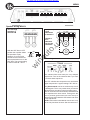
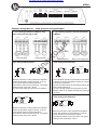
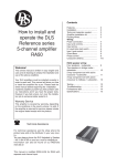
(044)361-05-06
ICQ:495-089-192
(067)469-02-12
ICQ:613-211-859
(099)048-99-03
(093)672-77-76
User's Manual
Car amplifier DLS MRA22 2-channel
In the online store Winauto you also can buy auto amplifier DLS MRA22 . Delivery in Kiev and throughout Ukraine with
payment upon receipt!
http://winauto.ua
Car Receivers - Facia Plates - Head Units - Car TVs and Monitors - Antennas - Car Audio - DVR - GPS Navigation - Trip Computers - Alarm
Systems - Mechanical Locking - Parking Systems - Car Cameras - Xenon and Lights - Established Optics - Tuning - Car Heating and Cooling Sound Marine and Electronics - Car Accessories - Isolation - Installation Components - Batteries, Power - Oils and Fluids -
Car audio and car goods internet store Winauto
Contents
Installation…………………….…….
Tools and materials needed……….
Amplifier installation kit…………....
How to install and operate the
DLS Marine Audio amplifiers
MRA22
MRA31
MRA41
to
.u
a
Wiring
Power and Remote……………..….
Input and controls
Input wiring Hi & Low level………..
Parallel input..................................
Hi/Low input switch........................
Fuses / Protect light.......................
Input level control...........................
Phase control.................................
Crossovers………….......................
Welcome!
in
au
This owners manual is written in easy english and
uses a lot of drawings to simply the installation and
use of the above amplifiers.
w
Your DLS amplifiers must be installed correctly in
order to work well. This manual will show you how
to install the amplifier like a pro. Please read the
entire manual before beginning the installation.
Install the amplifier yourself if you feel confident with
our instructions and if you have the proper tools.
However if you feel unsure, turn over the installation job to someone better suited to it.
Warranty Service
This amplifier is covered by warranty, depending
on the conditions in the country where it is sold. If
the amplifier is returned for service, please include
the original dated receipt with the product.
Technical Assistance
For technical assistance ask the shop where the
product was sold or the distributor in your very
country.You can always phone the DLS Helpdesk in
Sweden+ 46 31 84 00 60 or send an e-mail to
[email protected] can also be found on our WEBsite www.dls.se
DLS Svenska AB
P.O. Box 13029
SE-40251 Göteborg, Sweden
Tel: +46 31 840060
Fax: +46 31 844021
E-mail: [email protected]
www.dls.se
2
3
3
3
4
4
4
4
5
5
5
MRA 22 speaker wiring:
Front speakers…...………………....
Subwoofer…………………………...
6
6
MRA 31 speaker wiring:
Front speakers…...………………....
Subwoofer…………………………...
7
7
MRA 41 speaker wiring:
Four speakers……………………....
Two speakers + bridged subwoofer.
Two way front system with
active crossover……………….…….
9
Testing………………………………..
Troubleshooting……………………...
Professional tips……………………..
Specifications………………………...
10
10
11
12
8
8
All models include
RCA inputs
High Level input
Continuos variable low pass and high
pass crossover
Remote turn on / off
Automatic remote turn on/ off on high level
input without connecting any remote wire
Electronic protection circuitry against
short-circuit, DC offset and thermal overload.
Bridgeable design to direct full power to
one or two subwoofers etc.
IMPORTANT!
While these amplifiers are specially designed
for marine applications, they are not
waterproof and should not be mounted where
it is likely to get wet.
The cover is made to resist moisture as well
as the PC-board.
Car audio and car goods internet store Winauto
MRA22, MRA31, MRA41
Installation
Before you begin installation
Before you begin you need to read the manual, to have
some tools, cables and other material available. There
is one such list of material on the following page.
Amplifier location
Disconnect Battery
DLS logo on amplifier cooling flange
The DLS logo on top of the amplifier is attached
with two 1 mm hex. screws. The logo can be removed and twisted 90 or 180 degrees, and then
screwed back in wanted position. The logo can be
mounted in four different ways to match your installation.
in
au
Safety Considerations:
Your amplifier must be installed in a dry, wellventilated environment and in a manner which
does not interfere with your vessel’s factory
installed electronic devices. You should also take
the time to securely mount the amplifier so that it
does not come loose in the event of a collision or
a sudden jolt to the vessel.
a
The DLS Marine Audio amplifiers have a compact
design that allows great flexibility in mounting.
Before starting the installation, always disconnect
the negative terminal of
the battery.
to
.u
Important
Allow air circulation around the amplifier.
w
Check before drilling any holes in your vessel
to make sure that you will not be drilling through
the hull, a fuel tank, fuel line, wiring harness or
other vital vessel system.
Do not run system wiring outside or
underneath the vessel. This is an extremely
dangerous practice which can result in severe
damage to your vessel and person.
Protect all system wires from sharp edges
(metal, fiberglass, etc.) by carefully routing
them, tying them down and using grommets
and loom where appropriate.
Do not mount the amplifier in the engine
compartment or in any other area that will
expose the amplifier circuitry to the elements.
Do not mount the amplifier upside down!
This is the best way to
mount the amplifier to get
good cooling.
2
Removal of side flanges
In order to attach the amplifier to the surface and
connect speaker and power cables, the side
flanges must be removed. This is done by removing the hex screws on top of the amplifier. Use a
3 mm hex key.
Remove
these
screws using a 3
mm hex. key for
removal of side
flange. Remount
after attaching the
amplifier
and
connection of the
speaker and power
cables.
Car audio and car goods internet store Winauto
MRA22, MRA31, MRA41
Wiring
Tools and material needed
Connect power and remote
Connect the fuse holder as close to the vessel
battery + as possible, using AWG 8 = 10 mm2 or
heavier cable. Use a ring crimp terminal cable to
connect to battery +. Apply silicon grease to the fuse
to prevent corrosion. Use a 50 Amp fuse for both
amplifiers.
Tools:
Flat and Phillips screwdrivers
Wire cutter, Wire stripper
Electric drill with drills
Crimping tool
Digital multimeter or test lamp
Material:
Speaker wire: minimum
12 AWG = 4 mm2 for subwoofers
13 – 16 AWG = 1,5-2,5 mm2 for other
speakers
Stainless metal screws for mounting the
amplifier to the amplifier board and the
amplifier board to the vessel, and some
extra for fuse holder.
Electrical insulation tape
DLS FH1
fuse holder
Connect the battery cable by a crimp fork terminal
(spade ) to the +12 Volt on the amplifier. Do likewise
with the negative cable. If you use a AWG 8 = 10
mm2 or thinner cable, you can do without the crimp
terminal and put the cable right into the connector.
Be sure to use a rubber grommet or a plastic
insulating tube where the cable passes places when
it can easily be jammed. Use wire ties to secure to
existing cables.
w
in
au
to
.u
Amplifier installation kit:
If available, buy an amplifier installation kit. It
contains normally all you need. This is what you
have to buy if you buy the items separately.
Power cable,minimum 8 AWG = 10 mm2
for MRA22, 4 AWG = 21 mm2 for MRA 31/41.
1 pc of fuseholder to install close to the
battery + fuse 50 Ampere.
15 AWG = 1,5 mm2 wire for remote turn on /
off cable from radio / CD.
RCA-cable for input from radio.
Different lengths are available.
Two ring crimp terminals –one
for connection to the battery plus and one
for the battery minus connection.
Two heavy fork crimp terminals to connect
+ and – to amplifer – but you do only need
them if you use heavy cable or to make the
installation look nicer.
Four to ten fork crimp terminals to
connect the speaker cables – but you do
only need them if you use heavy cables or
want the installation to look nicer.
One fork crimp terminal to connect the
remote wire to the amplifier, but you need it
only to make it look nicer.
Four to eight splicers to connect speaker
cables to high level input cable, if high level
input is used.
Wire ties
a
To head unit
remote
If amplifier installation kits are available with different size of power cable, chose the most heavy
power cable to improve sound quality and to allow
more amplifiers to be installed now or later.
These are the minimum sizes we recommend for
the amplifiers:
MRA22
10 mm2 (7 AWG)
MRA31/41 21 mm2 (4 AWG)
This is for cable lengths up to 5 meters.
The ground cable must have the same size.
Remote terminal ( REM )
For RCA cable signal input:
Connect the radio power antenna lead = remote
turn on/off from the car stereo to the amplifier remote
connection. This turns on the amplifier when the
car stereo is turned on.
You can either use the built in remote cable in the
RCA cable itself or use a separate cable.
We recommend to use a separate remote wire and
run the RCA lead separate from remote wire, power
cables and speaker cables.
You can either use a crimp fork terminal or insert
the cable directly into the amplifier terminal. If there
is no remote voltage available from the stereo, you
must connect to the ignition key through the radio
or any accessories fuse.
For High Level input:
We recommend you to connect the remote wire as
described above. The amplifier will produce soft on
/ soft off operation this way. You must set the Hi
level/Low level switch to High level position in this
case.
In the case that there is no remote voltage available
from the car stereo or you want to simplify the installation, the amplifier can be turned on/ turned off
by the high level input voltage. This is done when
the Hi level/Low level switch is set to Hi level position. There is a small disadvantage that this function
gives soft turn on operation but some pop sound
when switching off.
3
Car audio and car goods internet store Winauto
MRA22, MRA31, MRA41
Inputs may be low level from the RCA output of the car
stereo or high level from the car stereo speaker output. Low level = RCA is to prefer for the best sound
quality.
Important
On MRA22 use either the low level or high level
input, do not use both at same time.
Low level input
Use a pair of shielded stereo audio cables with RCA
type jack. RCA cables are available in different
lengths up to 5,5 meters.
Avoid placing the RCA cable
close to speaker cables,
power cables and remote
control cable. Connect to input socket A/B.
MRA31 has also a separate
input (C) for the mono sub
channel.
High Level Input
White: A ch.+
White/Black: A ch.Grey/Black: B ch.Grey: B ch.+
Hi level input plug on amp for CH A/B.
High Input
(C/D Ch)
Violet: C ch.+
Violet/Black: C ch.Green/Black: D ch.Green: D ch.+
Hi level input plug on amp for CH C/D.
Hi / Low level input switch
To ensure best possible performance from the
amplifiers a switch is installed to select between Hi
and Low input.
When using High Level input:
Push in the button to position
”Hi Level”
When using Low level input:
Hi level
Push out the button to position
Low level
”Low Level”
in
au
Connect left and right speaker wires coming from
the car stereo to the high level input as shown. You
must connect both plus and minus as the inputs
are balanced, connecting plus only gives lower level
and bad sound quality. By changing the polarity of
plus and minus, you can change the phase.
High Input
(A/B Ch)
a
Input Wiring
MRA41 High level input sockets
The MRA41 four channel amplifier is connected
likewise, however we have four channels.
You can feed two channels from RCA and two
channels using high level input from rear speaker
cables.
to
.u
Input and controls
High Input
(C/D Ch)
w
MRA 22, MRA31 High level input socket
White: A ch.+
White/Black: A ch.Grey/Black: B ch.Grey: B ch.+
Hi level input
plug on amp.
MRA31
On MRA31 the high level signal is fed internally to
channel C when using high level input.
Automatic turn on when using high level input.
With the Hi/Low input swich set to Hi, the amplifier
turns on automatically on high input. You dont need
to connect a separate remote wire from your head
unit.
Parallel input on MRA31, MRA41
Parallel Input MRA31
Off PC
Parallel Input MRA41
Off
4
PCD
On MRA31 the PC position
internally connects the A/B input
with the input for channel C.
On MRA41 the PCD position
internally connects the A/B and
C/D inputs.
If the switch is set to wrong position, the amplifier
still works, but the risk for disturbances or distortion
increases.
RCA Output
Input
Output
A
A
B
B
Use RCA Outputs to
connect additional
amplifiers (not available on
MRA31).
Fuses
MRA31 and MRA41 uses two
30 ampere ATC blade type
fuses.
MRA22 uses one 25 A fuse.
Power Light / Protect light
Power
(Green)
Protect
(Red)
The power light (green ) comes on when
the amplifier is turned on.
The protect light ( red ) comes on
when the amplifier shuts down from
overheating, or a short circuit ( speaker failure)
Car audio and car goods internet store Winauto
MRA22, MRA31, MRA41
Input Level control
Low Pass Filter (LPF)
The input level control, 5V – 0,25 V,
Level
matches the output of your radio to
the input of the amplifier. After installation is complete, make sure the input of the amplifier is turned down all
5V 0,25V
the way ( counter-clockwise at 5V ).
Play a tape or CD, make sure all bass or treble
settings or equalizer are flat, and turn the volume of
the radio up until you just start to hear distortion.
Turn the volume control down just a bit. On the
amplifier increase the input level control ( clockwise
or to the right ) until you just start to hear distortion,
then back the level control just a bit. Now your radio
and amplifier levels are matched.
LPF
50Hz 500Hz
Off On
The LPF (low pass filter) mostly used for
subwoofers. It will allow low frequencies only and
blocks higher frequencies. A typical setting is 50 –
80 Hz. The filter can be switched in and out.
This is normally used for subwoofers
On MRA41 the filter can also be used for active
crossover in a 2-way speaker component kit, a
typical crocssover point is then 3,5 - 4 kHz.
Phase control MRA31
a
Subsonic filter MRA31
The Subsonic filter blocks the very
deepest frequencies from reaching the
subwoofers. It has a fixed frequency
of 25 Hz and can be switched On / Off.
For sub channel C only.
to
.u
The phase control on MRA31 can be set
continuously from 0 - 180 degrees. This is very
useful when you want to adjust the bass sound for
best front stage image. Start on 0 and turn the control
slowly clockwise until you experience that the bass
sound is coming from the front. If you dont get the
result you want, also try to
PHASE
phase reverse the subwoofer
connections and make
0 180
a new adjustment.
NOTE: This function is intended for car use and
may not be fully functional in boats. Set the control
to 0.
Filter frequency range:
MRA22: 50-500 Hz
MRA31: 50 - 120 Hz
MRA41:
Ch A/B: 50(500)Hz - 500(5k)Hz
80Hz 200Hz
All amplifiers include high pass filter
( HPF ) and low pass filters ( LPF).
All filters are continously variable and all filters can
be switched on and off. MRA31 also include a
subsonic filter.
High Pass Filter (HPF)
HPF
50Hz 220Hz
15Hz 500Hz
Off On
Filter frequency range:
MRA22: 15-150 Hz
MRA31: 50 - 150 Hz
MRA41:
Ch A/B: 15 - 500 Hz
Ch C/D: 15(150)Hz - 500(5k) Hz
Off On
Grand bass on MRA41
in
au
w
Crossovers
Subsonic
Grand Bass
40Hz 60Hz
25Hz
80Hz
0dB
18dB
Grand Bass is used to increase the bass volume
at an interval of bass frequencies. You can select
the center frequency between 25Hz and 80 Hz and
the amplification between 0 dB ( no amplification )
and 18 dB ( full amplification ).
The slope of the filter is 10 – 12 dB at maximum
setting.
This function is used to compensate for the bass
box function and to adjust for your own taste of
bass. Set level control at 0 dB if you want it to be
inoperative.
The HPF (high pass filter) blocks very low
frequencies from reaching the speakers. It is mostly
used at say 60 Hz to protect small speakers (like 6
inch and smaller) from deep bass. It can also be
used as subsonic filter to take away the very
deepest frequencies from a bass box. The typical
setting is then around 25 – 40 Hz.
The filter can be switched off if you want to run the
amplifier in full range mode.
On MRA41 the filter can also be used for active
crossover in a 2-way speaker component kit, a
typical crocssover point is then 3,5 - 4 kHz.
5
MRA41
in
au
to
.u
a
Car audio and car goods internet store Winauto
w
The MRA22 is a two channel stereo amplifier. It has
a variable high pass filter, (HPF) 15-500 Hz. It has
also a variable low pass filter, (LPF) 50-500 Hz for
subwoofer use.
HPF
LPF
80Hz 200Hz
50Hz 220Hz
50Hz 500Hz
15Hz 500Hz
Off On
Off On
The MRA41 is a four channel amplifier. It is mostly
used with a front system connected to channels C/
D and a subwoofer connected to channel A/B. You
will find speaker wiring and filter setting example on
page 9. Please observe the proper settings of the
channel A/B LPF multiplier switch and of the channel
C/D HPF multiplier switch.
The MRA41 can also be used to feed a 2–way front
system with active crossovers between midbasses
and tweeters. This is described in a speaker wiring
and filter setting example on page 10.
LPF
Multiply
80/800Hz 200/2(k)Hz
Off On50/500Hz
x1 x10
500/5(k)Hz
HPF
The MRA31 is a three channel amplifier. It has a
variable high pass filter, 50-150 Hz, for channel A/
B. The C channel is for subwoofers and has a
subsonic filter, a variable low pass filter, 50-120 Hz,
and a phase control variable from 0 - 180 degrees.
The subsonic filter can be switched IN-OUT and has
a fixed frequency of 25 Hz.
6
Multiply
50/500Hz 220/2(k)Hz
Off On
15/150Hz 500/5(k)Hz
x1 x10
Channel A/B is equipped very much like the MRA22,
however the LPF has a multiplier. Thus the frequency
range of the LPF can be varied from 50 Hz – 500 Hz
in the x1 position or 500 Hz – 5 kHz in the x10 position. This way we can use this amplifier to feed a 2way system, where the midbasses are fed from 80
Hz – 4 kHz.
The tweeters connected to channel C/D , operate
from 4 kHz upwards using the HPF in multiplier position x 10 150 Hz – 5 kHz.
Car audio and car goods internet store Winauto
MRA22
Speaker wiring MRA 22
One subwoofer connected in bridge mode to
MRA22
HPF
50Hz 220Hz
w
Filter settings
in
au
to
.u
a
Two fullrange speakers to MRA22
NOTE!
4 ohm minimum load when using bridge mode
connection. Lower impedances may damage the
amplifier. In bridge mode the amplifier sees a 4
ohm load as 2 ohm.
Filter settings
HPF
50Hz 220Hz
15Hz 500Hz
15Hz 500Hz
Off On
Off On
With the HPF-filter in OFF position the amplifier
allows the speakers to play fullrange. If you for
some reason want to limit the low bass
reproduction switch on the HPF-filter.
The typical setting is then 60 – 80 Hz.
The HPF filter is here used as subsonic filter to take
away the very deepest frequencies. The typical setting is around 25 – 40 Hz.
LPF
80Hz 200Hz
LPF
80Hz 200Hz
50Hz 500Hz
Off On
50Hz 500Hz
Off On
The LPF-filter should be OFF.
The LPF will allow low frequencies only and blocks
higher frequencies. A typical setting is 70 – 90 Hz.
7
Car audio and car goods internet store Winauto
MRA31
Speaker wiring MRA 31
Two fullrange
speakers to
channel A/B
One (or two)
4 ohm
subwoofers
to channel C
+
+ C CH -
-
HPF
in
au
90Hz 120Hz
50Hz 150Hz
Off On
Filter settings channel C
w
With the HPF-filter in OFF
position the amplifier allows
the speakers to play
fullrange. If you for some
reason want to limit the low
bass reproduction turn on the
HPF-filter. The typical setting
is then around 60 – 80 Hz.
to
.u
a
A single 2
ohm
subwoofer
can also be
connected.
The subsonic filter takes away the very deepest
frequencies. Turn on the subsonic filter if you want
to remove these frequencis.
The LPF will allow low frequencies only and blocks
higher frequencies. A typical setting is 60 – 80 Hz.
The phase control can be set continuously from 0
- 180 degrees. This is very useful when you want to
adjust the bass sound for best front stage image.
Start on 0 and turn the control slowly clockwise until
you experience the bass sound coming from the
front. If you dont get the result you want, also try to
phase reverse the subwoofer connections and make
a new adjustment.
NOTE: This function is intended for car use and may
not be fully functional in boats. Set the control to 0.
8
Car audio and car goods internet store Winauto
MRA41
Speaker wiring MRA 41 - three different wiring examples
1. Four fullrange speakers to MRA41. One
pair in front and one pair in rear.
to
.u
a
2. Two fullrange speakers and one subwoofer
to MRA41.
Front speakers
in
au
Rear speakers
Filter settings A/B Channels
LPF
HPF
50Hz 220Hz
LPF
HPF
Multiply
w
Off On50/500Hz
Rear or front speakers
Filter settings A/B Channels
x1 x10
Off On50/500Hz
15Hz 500Hz
500/5(k)Hz
Multiply
80/800Hz 200/2(k)Hz
50Hz 220Hz
80/800Hz 200/2(k)Hz
15Hz 500Hz
x1 x10
500/5(k)Hz
Off On
Off On
With the HPF-filter in OFF position the amplifier
allows the speakers to play fullrange. If you for
some reason want to limit the low bass
reproduction switch on the HPF-filter. The typical
setting is then around 60 – 80 Hz.
The LPF-filter switch should be in OFF-position
Filter settings C/D Channels
HPF
Rear subwoofer
Multiply
The subwoofer should be connected to channel A/B
in bridge mode.The Grand Bass mode can now be
used for the subwoofer.
Set the HPF-filter switch to ON-position. Adjust the
filter setting to 25-40 Hz.
Set the LPF-filter switch to ON-position and the
Multiply swich to x1. Adjust the frequency setting to
70-90 Hz.
Filter settings C/D Channels
50/500Hz 220/2(k)Hz
HPF
Off On
15/150Hz 500/5(k)Hz
x1 x10
Off On
With the HPF-filter in OFF position the amplifier
allows the speakers to play fullrange. If you for
some reason want to limit the low bass
reproduction switch on the HPF-filter. The typical
setting is then around 60 – 80 Hz.
Multiply
50/500Hz 220/2(k)Hz
15/150Hz 500/5(k)Hz
x1 x10
With the HPF-filter in OFF position the amplifier
allows the speakers to play fullrange. If you for
some reason want to limit the low bass
reproduction switch on the HPF-filter. The typical
setting is then around 60 – 80 Hz.
9
Car audio and car goods internet store Winauto
MRA41
Speaker wiring MRA 41
3. One 2-way speaker system to MRA41 using
active crossover between tweeter and
midrange / bass
D
Tweeters
Filter settings A/B Channels
LPF
HPF
50Hz 220Hz
in
au
Midrange
to
.u
a
C
Multiply
w
80/800Hz 200/2(k)Hz
Off On50/500Hz
15Hz 500Hz
x1 x10
500/5(k)Hz
Off On
We want a crossover point of 4 kHz between tweeter
and midrange. If you for some reason want to limit
the low bass reproduction switch on the HPF-filter.
The typical setting is then around 60 – 80 Hz. Switch
the LPF-filter switch to ON and the Multiply switch
to x10 position. Now you can adjust the filter setting
from 500 Hz to 5 kHz. Adjust the setting to 4 kHz.
Filter settings C/D Channels
HPF
Multiply
50/500Hz 220/2(k)Hz
Off On
15/150Hz 500/5(k)Hz
x1 x10
Channel C/D are used for tweeters and must be set
to play from 4 kHz and up. The HPF-filter switch
must be ON and the multiply swich in x 10 position.
Now you can adjust the filter setting from 150Hz to
5 kHz. Adjust the setting to 4 kHz.
10
Car audio and car goods internet store Winauto
MRA22, MRA31, MRA41
Testing
Troubleshooting
Before you finish the installation, you should do the
following tests to make sure the wiring is correct and
everything is operating properly.
If problems occour during the installation, or later,
this guide might help you to find out whats´s wrong.
THE AMPLIFIER IS DEAD:
1. Check power lead, ground and remote
connections at the amplifier using a multi meter.
2. Check the battery terminal connections.
3. Check the power lead fuse or circuit breaker. If
fuse damage continues, inspect the power lead
for short circuits.
4. Check the amplifier protection fuses. Are these
broken change to new ones with the same value.
If short circuiting continues, contact your local
DLS dealer. A fault may exist in the amplifier.
5. To start the amplifier requires a remote voltage of
9-15 volt. Check the voltage with a multi meter.
Reconnect Battery
a
When wiring is complete,
reconnect the battery
negative terminal.
2.
Turn on the head unit but do not turn up the
volume. The amplifier power light should
come on. If not, check the remote and +12
volt wires. Also check the ground
connection.
Turn up the head units volume slightly. All
speakers should operate. if not, check wiring
connections at amplifier and speakers.
AMPLIFIER PROTECTION FUSE BLOWS AT LOW
VOLUME :
1. One or more speaker cables are shorted. Make an
insulation test with a multi meter. The cables must not
have a connection to earth.
in
au
1.
to
.u
Test power wiring
Test speaker connections
w
Make sure the speakers are connected correct.
Use the balance control on the head unit to make
sure right channel is on right speaker etc. If
speakers don´t play at all, one or both speaker
wires may be disconnected.
THE AMPLIFIER TURNS OFF AFTER 10 - 30 MINUTES.
The amplifier is overheating due to inadequate ventilation. Check mounting position is free from obstruction.
Do this:
1.
Move the amplifier to a place with better ventilation.
2.
Install one or two fans to cool down the heatsink.
3.
Overheating can also be caused by an
impedance load below the level permitted.
NO OUTPUT FROM ONE OR MORE SPEAKERS:
Check the following:
1.
Balance control position.
2.
Fader control position.
3.
Speaker cable connections to both amplifier and
drivers.
4.
Signal lead plugs and cables.
5.
Change left and right signal lead plugs in the
amplifier to see if the problem moves to a different speaker, the lead has a fault.
If the problem remains, the speaker or amplifier
are at fault.
11
Car audio and car goods internet store Winauto
MRA22, MRA31, MRA41
Professional Tip:
Professional Tip:
NOISE PROBLEMS
SPEAKER POLARITY CHECK.
WHINING NOISE VARYING WITH ENGINE
REVOLUTIONS:
All speakers in a car audio system should be
connected in phase (the same polarity). All speaker cones must move in the same direction. Out of
phase speakers will cause a lack of bass, and a
poor stereo soundstage.
Do this:
1.
Rewire the power supply (12 V) to source
unit direct from battery.
Check all power connections to ensure that
they are clean and tight.
3.
Check quality of system ground connection.
4.
Install a Power Cap capacitor. This can be
helpful against most noise problems.
Do this:
1.
Ensure that all equipment has a common
ground point.
in
au
w
3.
Disconnect signal cables from amplifier to
see if noise disappears. If so the leads are
picking up noise. Test this by laying a new
cable over the seats and reconnecting to the
amplifier. If the noise does not return, reroute original cable away from source of
interference.
to
.u
CONSTANT WHINING NOISE:
2.
Checking polarity:
Hold the - connection of the speaker wire to the terminal of a 1,5 Volt flashlight battery. Tap the +
wire on to the + terminal of the battery, and observe
the movement of the cone. The cone should move
outwards when the wire touches the battery, and
inwards when the battery is removed. If it is the
other way around, the speaker has been connected
backwards and it must be removed and connected
correctly.
If your system also has a subwoofer connected
through a passive 6 or 12 dB crossover, try to
connect this with various polarity and judge what
sounds best. The phase shift in passive crossovers
sometimes makes it necessary to change polarity.
a
2.
Try to reduce the amplifiers input sensitivity.
If noise remains regardless of cable position,
try to use so called Quasi-balanced signal
cables. DLS PRO-cables are
Quasibalanced.
+
Battery
1,5 Volt
+
-
NOTE! Tweeters can not be tested this way, double
check the connections instead.
Professional Tip:
Securing wires
Use wire ties to bundle together when possible.
(But never bundle speaker wires or signal cables
together with power wires.
Professional Tip:
Crimp connections
Purchase crimp connectors and crimping tool.
Connectors are color coded.
1. Strip 1/4 inch (6 mm) of insulation from the wire.
2. Insert into connector
3. Crimp tightly
12
Professional Tip:
Speaker and power wires
Do not run speaker and power wires next to each
other. Power wires can generate a ”siren” sound in
the speakers. Run speaker and power wires
separated from each other.
Car audio and car goods internet store Winauto
MRA22, MRA31, MRA41
Specifications
MRA 22
MRA41
Number of channels
Power output, 4 ohm (0,1% THD)
Power output, 2 ohm (0,2% THD)
Power output, 4 ohm bridged
Signal to noise ratio, A-weighted
Damping factor
Frequency response
Input impedance, low level
Input impedance, high level
High level input with auto start
Low output (RCA output)
Input sensitivity
Grand bass adjustable frequency
Grand bass adjustable gain
Filter highpass /subsonic
Filter lowpass
* can be switched in/out
Power consumption, idle
Fuse
Dimensions HxWxD(mm)
Dimensions (inch)
Weight
2
4
2 x 60 W
2 x 100 W
1 x 200 W
>100 dB
>100
10 Hz - 35 kHz
>10 kohm
100 ohm
Yes
Yes
0,25 - 5V
0 - 18 dB
15-500 Hz*
50-500 Hz*
4 x 70 W
4 x 125 W
2 x 200 W
>100 dB
>100
10 Hz - 35 kHz
>10 kohm
100 ohm
Yes
Yes
0,25 - 5V
25 Hz - 80 Hz
0 - 18 dB
see spec. below
see spec. below
0,5 A
1 x 25 A
70x230x268
2,92x9,06x10,55
2,7 kg
1,0 A
2 x 30 A
70x372x268
2,92x14,65x10,55
4,2 kg
to
.u
MRA 31
in
au
DLS MARINE AUDIO
3
2 x 65 W
2 x 90 W
1 x 170 W
1 x 170 W
1 x 280 W
>100 dB
>100
10 Hz - 35 kHz
>10 kohm
100 ohm
Yes
No
0,25 - 5V
0-180 degrees
50-150 Hz*
50-120 Hz*
Fixed 25 Hz*
w
Number of channels
Power output, 4 ohm (0,1% THD)
Power output, 2 ohm (0,2% THD)
Power output, 4 ohm bridged
Power out mono sub ch. 4 ohm
Power out mono sub ch. 2 ohm
Signal to noise ratio, A-weighted
Damping factor
Frequency response
Input impedance, low level
Input impedance, high level
High level input with auto start
Low output (RCA output)
Input sensitivity
Variable phase shift control CH C
Filter high pass CH A & B
Filter low pass CH C
Subsonic filter CH C
* can be switched in/out
Power consumption, idle
Fuse
Dimensions HxWxD(mm)
Dimensions (inch)
Weight
a
DLS MARINE AUDIO
Filter configuration MRA41
Channel A/B:
Highpass: 15 - 500 Hz*
Lowpass: 50(500) - 500(5k) Hz*
(x 10 switch)
Channel C/D:
Highpass: 15(150)Hz - 500(5k)Hz*
(x 10 switch)
* can be switched in/out
1,0 A
2 x 30 A
70x357x268
2,92x14,06x10,55
4 kg
All output power ratings at 13,8 VDC
We follow a policy of continuous advancement in
development.
For this reason all or part of specifications & designs
may be changed without prior notice.
13
w
in
au
to
.u
a
Car audio and car goods internet store Winauto