1
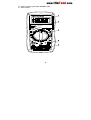
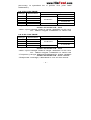
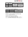
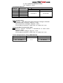
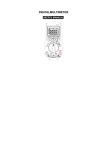
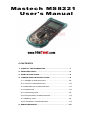
Mastech MS8221
User's Manual
CONTENTS
1. SAFETY INFORMATION…………………………….1
2. DESCRIPTION………………………………………..4
3. SPECIFICATIONS…………………………………….6
4. OPERATING INSTRUCTION………………………..9
4.1 Voltage measurement…………………….……..10
4.2 Current measurement……………………………10
4.3 Resistance measurement…………………….....12
4.4 Diode test………………………………………….12
4.5 Continuity test…………………………………….13
4.6 Temperature measurement……………………...13
4.7 Battery test………………………………………..14
4.8 Transistor measurement…………………………14
5. MAINTENANCE………………………….…………..15
1. SAFETY INFORMATION
WARNING
To ensure safe operation, and in order to
exploit to the full the functionality of the meter,
please follow the directions in this section
carefully.
This multimeter has been designed according to
IEC-1010 concerning electronic measuring instruments
with an overvoltage category CAT II 1000V, CAT III
600V and pollution 2.
Follow all safety and operating instructions to ensure
that the meter is used safely and is kept in good
operating condition.
With proper use and care, the digital meter will give you
years of satisfactory service.
1.1 PRELIMINARY
- When using the meter, the user must observe all
normal safety rules concerning:
Protection against the dangers of electrical current.
Protection of the meter against misuse.
- When the meter is delivered, check that it has not
been damaged in transit.
- When poor condition under harsh preservation or
shipping conditions caused, inspect and confirm this
meter without delay.
- Test leads must be in good condition. Before using
-1-
verify that the insulation on test leads is not
damaged and/or the leads wire is not exposed.
- Full compliance with safety standards can be
guaranteed only if used with test leads supplied. If
necessary, they must be replaced with the same
model or same electric ratings.
1.2 DURING USE
- Before using, you must select the right input jack,
function and range.
- Never exceed the protection limit values indicated in
specifications for each range of measurement.
- When the value scale to be measured is unknown
beforehand, set the range selector at the highest
position.
- Do not measure voltage if the voltage on the
terminals exceeds 1000V above earth ground.
- Always be careful when working with voltages above
60V DC or 30V AC rms, keep fingers behind the
probe barriers while measuring.
- Before rotating the transform switch to change
functions and ranges, disconnect test leads from the
circuit under test.
- Never perform resistance, temperature, transistor,
diode and continuity measurements on live circuits.
- Never use the meter under the condition of the
explosive air, steam or dirt.
- If any faults or abnormalities are observed, the meter
-2-
can not be used any more and it has to be checked
out.
- Never use the meter unless the rear case is in place
and fastened fully.
- Please do not store or use meter in areas exposed to
direct sunlight, high temperature, humidity or
condensation.
1.3 SYMBOL
Caution: refer to the instruction manual.
Incorrect use may result in damage to the
device or its components.
Earth
This instrument has double insulation.
Fuse: F 200mA/250V
1.4 MAINTENANCE
- Please do not attempt to adjust or repair the meter by
removing the rear case while voltage is being applied.
A technician who fully understands danger involved
should only carry out such actions.
- Before opening the battery cover or case of the meter,
always disconnect test leads from all tested circuits.
- To avoid the wrong reading causing electricity attack,
when the meter displays“ ”, you must change the
-3-
battery.
- For continue protection against fire, replace fuse only
with the specified voltage and current ratings: F
200mA/250V (quick acting).
- Do not use abrasives or solvents on the meter, use a
damp cloth and mild detergent only.
- Always set the power switch to the OFF position when
the meter is not in use.
- If the meter is to be stored for a long period of time, the
batteries should be removed to prevent damage to the
unit.
2. DESCRIPTION
- This meter is a portable professional measuring
instrument with handsome LCD easily reading.
- Single operation of a transform switch makes
measurement convenient. Overload protection and
low battery indication are provided, this meter is
ideal for use in the fields, workshop, school, hobby
and home applications.
- This meter is with the functions of data hold.
NAME OF COMPONENTS
1. LCD display
2. Hold key
3. Rotary switch
-4-
4. hFE socket (except MS8221D)
5. Terminals
-5-
3. SPECIFICATIONS
3.1 GENERAL SPECIFICATIONS
- Environment conditions:
600V CAT.III and 1000V CAT.Ⅱ
Pollution degree: 2. Altitude < 2000 m.
- Operating temperature:
0~40OC (32℉ to 104℉), (<80% RH, non-condensing)
- Storage temperature:
-10~50 OC(14℉ to 122℉), (<70% RH, battery removed)
- Temperature Coefficient:
0.1×(specified accuracy) / OC (<18 OC or >28 OC)
- MAX. Voltage between terminals and earth ground:
750V AC rms or 1000V DC
- Fuse Protection: mA: F 200mA/250V ∅5×20,
10A: unfused.
- Display: LCD, 1999counts, updates 2-3/sec.
- Over Range indication: LCD will display "1".
- Low battery indication:
The "
" is displayed on the LCD.
- Polarity indication: "−" displayed automatically.
- Power source: 4.5V
- Battery type: AAA 1.5V
- Dimensions: 158(L)×74(W)×31(H) mm.
- Weight: 220g. Approx. (battery included).
3.2 Measurement specifications
Accuracy: ±(% of reading + number of digits) at 18°C to
28°C (64°F to 82°F) with relative humidity to 80%.
-6-
(Accuracy is specified for a period one year after
calibration)
3.2.1 DC VOLTAGE
Range
Resolution
Accuracy
MS8221A/8221D
MS8221B/8230B
0.2V
0.1mV
±0.5%±2
2V
1mV
±0.5%±3
±0.5%±1
20V
0.01V
±0.8%±3
200V
0.1V
1000V
1V
±0.8%±2
±0.8%±5
- Input impedance: MS8221A/MS8221D: 10MΩ
MS8221B/MS8230B: 1MΩ
- Max. input voltage: 200mV range: 250VDC or AC rms
2V - 1000V ranges: 1000VDC or 750V rms
3.2.2 AC VOLTAGE
Range
Resolution
Accuracy
MS8221A/8221D
MS8221B/8230B
2V
1mV
±0.8%±3
20V
10mV
200V
0.01V
±1.2%±5
750V
1V
±1.2%±3
- Input impedance: MS8221A/MS8221D: 10MΩ
MS8221B/MS8230B: 1MΩ
- Max. input voltage: 200mV range: 250VDC or AC rms
2V - 1000V ranges: 1000VDC or 750V rms
- Frequency range: MS8221A/MS8221D: 40Hz-1000Hz
MS8221B/MS8230B: 40Hz-400Hz
- Response: Average, calibrated in rms of sine wave.
-7-
3.2.3 DC CURRENT
Range
Resolution
Accuracy
MS8221A/8221D
MS8221B/8230B
200uA
0.1uA
±1.0%±2
±0.8%±1
2mA
1 uA
20mA
10 uA
±1.5%±2
200mA
100uA
±1.2%±1
10A
10mA
±2.0%±5
±3.0%±2
Overload protection: F250mA/250V fuse (10A range
unfused).
Max. Input Current: mA Jack: 200mA, 10A Jack: 10A
3.2.4 AC Current (MS8221A/MS8221D)
Range
Resolution
Accuracy
2mA
1µA
±1.2%±3
20mA
10µA
200mA
0.1mA
±2.0%±3
10A
10mA
±3.0%±7
Overload protection:F250mA/250V fuse (10A range
unfused).
Max. input current: mA: 200mA dc or 200mA ac rms
10A: 10A continuous, 20A 15 sec. Max
Frequency Range: 40Hz-1kHz
Indication: Average (rms of sine wave)
3.2.5 Transistor hFE (Except MS8221D)
Display: read approximate hFE value (0~1000) of
transistor under test (ALL TYPE).
Test condition: base current approx. 10µA (MS8221A)
or 2µA (MS8221B/MS8230B).
VCE: approx. 2.8V
3.2.6 Resistance
Accuracy
Range
Resolution
-8MS8221A/8221D
MS8221B/8230B
200Ω
0.1Ω
±0.8%±3
±1.0%±3
2KΩ
1Ω
20KΩ
10Ω
±0.8%±1
±1.0%±2
200KΩ
100Ω
2MΩ
1kΩ
20MΩ
10kΩ
±1.0%±2
Overload protection: 250V DC or 250V AC rms.
3.2.7 Diode test
Display: read approximate forward voltage of diode
Forward DC Current: approx. 1mA
Reversed DC Voltage: approx. 2.8V
Overload protection: 250V DC or 250V AC rms
3.2.8 Audible continuity test
Built-in buzzer sounds if resistance is less than
approx. 50Ω.
Open circuit voltage: approx. 2.8V
Overload protection: 250V DC or 250V AC rms
3.2.9 Temperature (Only MS8221B)
Range
Resolution
0℃ to 400℃
Accuracy
±5.0%±4
-20℃ to 0℃
1℃
±1.0%±3
400℃ to 1000℃
±2.0%±3
- Overload Protection: 250V DC or rms AC
3.2.10 Battery Test (Only MS8221D)
Range
Accuracy
Discharge current
-91.5V
100mA
±0.8%±1
9V
6mA
Overload protection: 1.5V: F250mA/250V fuse
9V: 250Vdc or 250Vac rms
4. OPERATING INSTRUCTION
4.1 Voltage measurement
or V~ range.
- Set rotary switch to the desired V
- Connect the black and red test leads to the COM and
V terminals respectively.
- Connect the test leads to the circuit being measured
- Read the displayed value. The polarity of red test lead
connection will be indicated when making a DCV
measurement.
- When only the figure “1” is displayed, it indicates
overrange situation and the higher range has to be
selected.
To avoid electrical shock and/or damage to
the instrument, do not attempt to take any
voltage measurement that might exceeds
1000Vdc or 750Vac rms. Do not apply more
than 1000Vdc or 750Vac rms between the
common terminal and the earth ground.
4.2 Current measurement
- Set the rotary switch to the desired A
or A~ range.
- Connect the black test lead to the COM terminal and
the red test leads to the mA terminal for a maximum of
200mA. For a maximum- 10
of -10A, move the red test
lead to the 10A terminal.
- Connect test leads in series with the load in which the
current is to be measured.
- Read the displayed value. The polarity of red test lead
connection will be indicated when making a DCA
measurement.
- When only the figure "1" displayed, it indicates
overrange situation and the higher range has to be
selected.
* MS8221B/MS8230B don’t have ACA measurement
function.
To avoid damage to the meter, use the proper
terminals, function, and range for your
measurement.
NOTE:
- When only the figure ‘OL’ is displayed, it indicates
overrange situation and the higher range has to be
selected.
- When the value scale to be measured is unknown
beforehand, set the range selector at the highest
position.
- “ ” means the socket of INPUT maximum current is
200mA, over current will destroy the fuse. 10A’s
maximum current is 10A, no fuse protection.
4.3 Resistance measurement
- Connect the black test lead to the COM jack and the
- 11 red test lead to the Ω jack.
- Set the transform switch at the Ω range position.
- Connect test leads across the resistance under
measurement.
- You can get reading from LCD.
To avoid electrical shock and/or damage to
the instrument, disconnect circuit power and
discharge all high-voltage capacitors before
measuring resistance.
NOTE:
- For measuring resistance above 1MΩ, the meter may
take a few seconds to stabilize reading. This is normal
for high resistance measuring.
- If the resistance being measured exceeds the
maximum value of the range selected or the input is
not connected, an overrange indication "1" will be
displayed..
4.4 Diode test
- Set the rotary switch to
range.
- Connect the black and red test leads to the COM and
Ω terminals respectively.
- Connect the red test lead to the anode, black test lead
to the cathode of the diode under testing.
- The meter will show the approx. forward voltage of the
- 12 -
diode. If the lead connection is reversed, only figure
"1" displayed.
To avoid electrical shock and/or damage to
the instrument, disconnect circuit power and
discharge all high-voltage capacitors before
testing diodes.
4.5 Continuity test
- Set the rotary switch to
range.
- Connect the black and red test leads to the COM and
Ω terminals respectively.
- Connect the test leads to the resistance in the circuit
being measured.
- When the test lead to the circuit is below 50Ω, a
continuous beeping will indicate it.
To avoid electrical shock and/or damage to
the instrument, disconnect circuit power and
discharge all high-voltage capacitors before
testing for Continuity.
4.6 Temperature measurement (Only MS8221B)
- Set the transform switch at the TEMP range position.
- The LCD display will show the current environment
temperature.
- When measuring the temperature with thermocouple,
‘K’ type probe for this meter can be used. Insert the
black plug to the COM jack and the red one to the
TEMP jack, touch the end of the temperature sensor
- 13 -
to the area or surface of the object for measurement.
- You can get reading from LCD.
To avoid electrical shock, do not connect the
thermocouples with the electriferous circuit.
4.7 Battery test (only MS8221D)
- Set the rotary switch to desired BATT range.
- Connect the black and red test leads to the COM and
VΩ terminals respectively.
- Connect the test leads across the battery terminals
under measurement.
- Read LCD display and determine if the battery is OK.
4.8 Transistor measurement
- Set the rotary switch to hFE range.
- Determine whether the transistor to be tested is NPN
or PNP type and locate the Emitter, Base and
Collector leads.
- Insert leads of the transistor into proper holes of the hFE
socket.
- The meter will show the approx. hFE value at test
condition of base current 10μA and Vce 2.8V.
To avoid electrical shock and/or damage to the
instrument, before attempting to insert
transistors for testing, always be sure that test
leads have been disconnected from any
measurement circuits.
5. MAINTENANCE
5.1 General Maintenance- 14 Periodically wipe the case with a damp cloth and mild
detergent. Do not use abrasives or solvents.
Dirt or moisture in the terminals can affect readings.
To clean the terminals:
¥ Turn the meter off and remove all test leads.
¥ Shake out any dirt that may be in the terminals.
¥ Soak a new swab with a cleaning and oiling agent
(such as WD-40).
¥ Work the swab around in each terminal. The oiling
agent insulates the terminals from moisture-related
contamination.
To avoid electrical shock or damage to the
meter, do not get water inside the case.
Remove the test leads and any input signals
before opening the case
5.2 Fuse replacement
To replace the Meter's fuse (see the Figure):
- Set the rotary switch to OFF range.
- Disconnect test leads from any inputs terminals.
- Use a screwdriver to unscrew the two screws secured
on the battery cover.
- Separate the battery cover from the bottom case.
- Replace the fuse only with specified ratings:
F 200mA/250V ∅5×20 (quick acting).
- Replace the battery cover and secure by the two
screws.
- 15 -
Before replacing the fuse, disconnect test
leads from any circuit under test.
To prevent damage or injury, replace the fuse
only with specified ratings.
5.3 Battery replacement
To replace the battery (see the Figure):
- When the battery voltage drop below proper operation
symbol will appear on the LCD display
range the
and the battery need to be replaced.
- Turn the meter off and remove all test leads.
- Use a screwdriver to unscrew the two screws secured
on the battery cover, and remove the battery cover.
- Replace the battery with three new 1.5V battery
(AAA).
- Reinstall the battery cover and secure by the two
screws.
Before replacing the battery, disconnect test
leads from any circuit under test, turn the
meter off and remove test leads from the
input terminals.
ACCESSORIES
⑴
⑵
⑶
⑷
Test Leads
Battery:1.5V, AAA
Instruction Manual
Thermocouple (K type) (Only MS8221B)
- 16 -
one set
three pieces
one piece
one piece
CAUTION
Using this appliance in an environment with a
strong radiated radio-frequency electromagnetic
field (approx. 3V/m), may influence its measuring
accuracy. The measuring result can be strongly
deviating from the actual value.
- 17 -