1
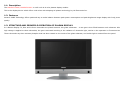
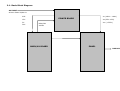
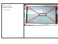
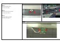
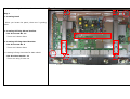
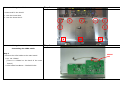
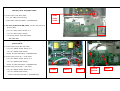
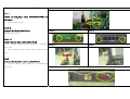
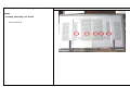
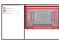
Service Manual PDP(PLASMA DISPLAY PANEL)TV Panel Grade; HD Ready Buyer Model No.: DT-42D2 Manufacturer Model No.: DPB-4260 DIGITALDEVICE, INC Contents 1. Specifications 1-1. Descriptions 1-2. Features 1-3. Structure and Principle Operation of PLASMA DISPLAY 1-4. General Specification 1-5. Operation Environmental Conditions 1-6. Storage Environmental Conditions 1-7. Mechanical Test Conditions 1-8. Life Expectancy 2. Block Diagram 2-1. Basic Block Diagram 2-2. Panel Block Diagram 2-3. A/V Board Block Diagram 3. Assembling 3-1. Assembly Diagram 3-2. Part Name 1. Specification 1-1. Descriptions 1-2. Features 1-3. Structure and Principle Operation of PLASMA DISPLAY 1-4. General Specification 1-4-1. Specification 1-4-2. I/O Description 1-5. Operation Environmental Conditions 1-6. Storage Environmental Conditions 1-7. Mechanical Test Conditions 1-8. Life Expectancy 1-1. Description The PDP42V7####/ PDP42X3#### is a 42-inch 16:9 color plasma display module. This is the display device which offers vivid colors with adopting AC plasma technology by LG Electronics Inc. 1-2. Features Smart P-CUBE Technology offers optimized way to make balance between peak power consumption and peak brightness image display with lively picture quality. 1-3. STRUCTURE AND PRINCIPLE OPERATION OF PLASMA DISPLAY In a Plasma Display TV, Row and Column electrodes are placed between two glass substrates. A rare gas is then filled between each substrate. When a high voltage is applied to these electrodes, the gas is activated resulting in the radiation of ultraviolet light, similar to the operation in fluorescent lamps. These ultraviolet rays then activate phosphor that has been coated on the inside of the glass substrate, and visible light is emitted from the panel. 1-4. General Specification 1-4-1. Specification (LG 42” HD PANEL) TV, Power Voltage AC100V~240V, 50/60㎐ Display Mode Input Signal Video, S-Video, SCART(Video/ S- Video/ RGB), Component, Analog RGB, HDMI(Digital RGB) Display Panel Consumption < 410W (Typical Full White) Screen Size 920 mm (H) × 518 mm (V) Number of Pixels 1024 (Horizontal) × 768 (Vertical) Aspect Ratio 16:9 AV1[SCART-VIDEO(P), RGB(P) / L,R(S)] Pixel Pitch 900um (H) x 676um (V) AV2[SCART-VIDEO(P), Input/Output Video System NTSC, PAL, SECAM RF RF IN (NTSC F-TYPE, PAL DIN-TYPE) Input Analog RGB(P), HDMI(DVI(P)) / RGB(S) S-VIDEO(P) L,R(S)] Color Arrangement RGB vertical stripes AV3[V, L,R] , S-VIDEO(P) Gradations 1024 steps for each RGB Component [Y, Pb, Pr(S) / L, R(S)] Brightness 1000 cd/m2 Contrast Ratio 5000 :1 Displayable Colors 1,070,000,000 Colors Weight Without Stand 37 Kg Viewing Angle Over 160 degrees Dimensions Without Stand 1113 mm(W)×744mm(H) ×61.2 mm (D) Output Monitor Out (V, L, R)/ SCART(V, L, R) Speaker Out (L, R) (Option : Built-in speaker) / 1-4-2. I/O Description 1-4-2-1. Front Panel Control 1-4-2-2. Rear Cabinet I/O's - Standby power ON/OFF Button. - AC Power Input - Channel UP Button. - RF(TV) connector for antenna Input - Channel DOWN Button. - S-VIDEO Input(ATSC option) - Volume UP Button. - Composite Video RCA Input(ATSC option) - Volume DOWN Button. - Line Level Audio RCA Input(ATSC option) - AV Button. - SCART1/2 Input/Output(PAL/SECAM option) - Remote Controls Sensor (IR) - Component Video Input - Operation Indicator (LED) - Component Line Level Audio Input - RGB D-sub Connector Input - RGB Audio Input - HDMI (DVI) Input - Software Upgrade port - Speaker Output : 2CH (4210~70 model option) - Built-in Speaker S/W (4210~70 model option 1-5. Operation Environmental Conditions Temperature 0 to 40 °C Humidity 20 to 80% RH (without condensation) Atmospheric pressure 800 to 1100 hPa 1-6. Storage Environmental Conditions Temperature -20 to 60 °C Humidity 10 to 90% RH (without condensation) Atmospheric pressure 700 to 1100 hPa 1-7. Mechanical Test Conditions Vibration (operating) (Mounted in TV set) 4.9m/s2 (0.5 G), 10 to 55 Hz(Sweep Time : 2 Min), X / Y / Z directions, 10 minutes each Vibration (non-operating) (5EA Packed State) 4.9m/s2 (0.5 G), 10 to 55 Hz(Sweep Time : 2 Min), Y directions, 60 minutes each Drop 1-8. Life Expectancy The anticipated life-time is estimated more than 60,000 hours of continuous operations. ※ Average life time is the time when the brightness level becomes half of its initial value. 2. Block Diagram 2-1. Basic Block Diagram 2-2. Panel Block Diagram 2-3. MAIN/AV Board Block Diagram 2-1. Basic Block Diagram AC INPUT AC100~240V 50/60 Hz S5V 12V 5V 30V Vs (180V ~ 190V) POWER BOARD Va (55V ~65V) Vcc (+5.25v) Relay ON VS ON MAIN/AV BOARD PANEL DISPLAY 2-2. Panel Block Diagram Display Data (LVDS Input) RA+ RARB+ RBRC+ Memory RCRD+ RDRCLK+ RCLK- Common Controller Input Scan Color Plasma Display Panel Sustain Driver 852 X 480 Pixels Driver Interface Display Data Controller Driver Driving Timing Controller Various Voltages Vs (180V ~ 190V) Va (55V ~65V) Vcc (+5v) Address Driver 3. Assembling 3-1. Assembly Diagram 3-1-1. DPB-4260(Front Assembly) 3-2. Part Name 3-2-1. Screw Part Name 3-2-2. Cable List 3-1-1. DPB-4260 3-1-1-1. Assemblage of Filter Optical Put down slowly the filter optical to front Step1 3-1-1-2. Assemblage Front Retainer Step1 There’s are 4 retainer (Left, Right, Top, Bottom) - Use the screw No.5 Screw Point 3-1-1-3. Assemblage of Left/Right Speaker Step1 Unit Step1 Assemblage of Left Speaker Unit - Use the screw No.13 * speaker terminal is Left position Step2 Assemblage of Right Speaker Unit - Use the screw No.13 * speaker terminal is Right position Step2 3-1-1-4. Assemblage of LED, IR Step 1 Step 1 Assemble Window deco - Use the screw No.5 Step 2 Assemble Front Deco at Front - Use the screw No.15 Step 3 Assemble LED, IR Board - Use the screw No.14 Step3 Step2 3-1-2-9. Locating the Mount bracket and Inlet Step 1 2 2 Step 1 1. Locating Panel - When you locate the panel, there are 2 guiding holes 2. Locating & Fixing Mount bracket - Use the screw No. 12 4 There are 8 Screw Point 3. Locating & fixing Stand bracket 3 3 - Use the screw No. 3 There are 8 Screw Point 4. Locating & fixing Hexa Nut for Main shield - Use the Hexa nut No. 11 There are using 3 hexa nut 1 2 2 1 3-1-2-10. Fixing the shied Step 1 - Locate and fix the shield. 1. Use the Screw No.4 2. Use the Screw No.12 1 1 1 1 1 1 1 2 3-1-2-11. Fixing the main board and 2 2 Step 1 Connecting the LVDS cable. Step 1 - Connect the LVDS cable to the main board. * Loc. No. CON16 (There is a CON16 on the back of the main board.) * LVDS cable Part Name : DD42CO31301 CON16 < In case of the LG42 SD panel > Step 2-1. In case of the LG42 SD panel Step 2-2. In case of the LG42 HD panel Step 2-1 - Connect the LVDS cable to the digital board of the panel. * Loc. No. P1 (Digital board) P1 P201 Step 3 - Locate and fix the main board. < In case of the LG42 HD panel > Step 2-2 - Connect the LVDS cable to the digital board of Step 3 the panel. * Loc. No. P201 (Digital board) Step 3 - Locate and fix the main board. 1 1. Use the Screw No.6 1 2. Use the Screw No.12 1 1 1 2 1 1 1 2 3-1-2-12. Connecting the noise filter cable and the power 2P jumper cable. 2 1) Connect the noise filter cable. CN01 * Loc. No. CN01 (Power board) CN02 * Noise filter cable Part Name : DD42NF02451 CN03 2) In case of the LG42 HD panel, connect the power 2P 1 jumper cable. * Loc. No. CN02 (Power board) ÅÆ Loc. No. CN03 (Power board) * Power 2P jumper cable Part Name : DD-42KK-JMP/ 3-1-2-13. Connecting the power cables to the power board. 1) Connect the power 4PÅÆ4P cable . * Loc. No. CN802 (Power board) ÅÆ Loc. No. CON31 (Main board) *Power 4P cable Part Name : DD42NR04401 2) Connect the power 7P<--Æ12P cable. * Loc. No. CN801 (Power board) ÅÆ Loc. No. CON18 (Main board) *Power 7P cable Part Name : DD42NR07501 3) Connect the power 12P<--Æ7P cable. * Loc. No. CN803 (Power board) ÅÆ Loc. No. CON36 (Main board) *Power 12P cable Part Name : DD42NR12501 CN803 CN802 CN801 CON18 CON36 CON3 3-1-2-14. Assemblage of Key/LED/IR Board Step 1 Step 1 Connect the key_led_ir cable( 14P:DD42CO14601) to main board. Loc .CON25 Loc. CON25 (Main board) Step 2~3 Assemble Key Knob & Key Board Step 2 Step 3 Step 4 Step5 Use the screw No.13 Step 4 ~5 Connect the key_led_ir cable to Key Board Loc. CON25 (Main board) ÅÆ Loc. WO2(KEY board: 8P) * after assemble Key cable than assemble Key Ass’y. Loc. WO2 Step 6 Connect the key_led_ir cable to Led_Ir Board Loc. CON25 (Main board) ÅÆ Loc. WO1(LED_IR board: 6P) Step6 Loc. WO1 3-1-2-19. DPB-4260 Assemblage of rear Shield Step1 Locating and fixing rear shield - Use Screw No.6 Step 1 3-1-2-20. DPB-4260 Assemblage of rear Shield Step 2-left top Step2 Locating and fixing rear shield - Use Screw No.5 Step 3 - right top Step3 Locating and fixing rear shield - Use Screw No.5 Step4 Locating and fixing rear shield - Use Screw No.5 Step5 Locating and fixing rear shield - Use Screw No.5 Step 4- left & left bottom Step 5- right & right bottom 3-1-2-21. DPB-4260 Assemblage of Rear Cover Step1 - Use Screw No.7 - - Use Screw No.15 Use screw No.4 Step1 3-2. Part Name 3-2-1. Screw Part Name NO. IMAGE SORT NAME / SPEC NO.1 MACHINE SCREW + PAN HEAD P+4*6 (4*6=diameter*length) NO.2 TOP TITE + PAN HEAD T/T-BP+3*6 NO.3 MACHINE SCREW + WASHER + PAN HEAD WP+4*8 BLACK NO.4 MACHINE SCREW + WASHER + PAN HEAD WP+3*6 BLACK N0.5 TOP TITE + PAN HEAD T/T-BP+4*8 N0.6 MACHINE SCREW + PLAIN WASHER + SPRING WASHER SW/PW BP+3*8 N0.7 MACHINE SCREW + PLAIN WASHER + SPRING WASHER SW/PW BP+5*12 N0.8 N0.9 MACHINE SCREW + PAN HEAD MACHINE SCREW + PAN HEAD + EXTERNAL TEETH WASHER BP+4*6 T/T CT BB+4*10 N0.10 HEXA NUT HEXA NUT N0.11 HEXA NUT HEXA NUT 15mm N0.12 TOP TITE + PAN HEAD T/T-BP+4*12 N0.13 TOP TITE + PAN HEAD T/T-BP+3*8 N0.14 TOP TITE + PAN HEAD T/T-BP+3*6 N0.15 TOP TITE + PAN HEAD T/T-BP+4*10 3-2-2. Cable List No. PART NAME 1 DD42NF02451 2 DD-42KK-JMP/ 3 PIN Q`ty CONNECTION Remarks 1 CN01 (POWER B/D) NOISE FILTER 2P 1 CN02 (POWER B/D) Å---Æ CN03 (POWER B/D) POWER B/D DD42NR04401 4P 1 CN802(POWER B/D) Å---Æ CON31 (MAIN B/D) 4 DD42NR07501 7P 1 CN801 (POWER B/D) Å---Æ CON18 (MAIN B/D) 5. DD42NR12501 12P 1 CN803 (POWER B/D) Å---Æ CON36 (MAIN B/D) 6 DD42CO31301 31P 1 CON16 (MAIN B/D) Å---Æ P1 or P201 (DIGITAL B/D) MAIN B/D 7 DD42CO14601 14P 1 CON25 (MAIN B/D) Å---Æ WO1, WO2(KEY_LED_IR B/D) KEY_LED_IR B/D 8 DD4CO06701 4P 1 CON15 Å---Æ Speaker BUIL-IN SPEAKER