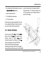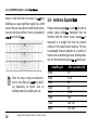
1
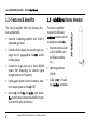
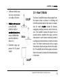
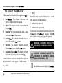
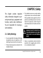
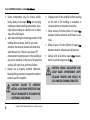
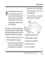
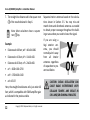
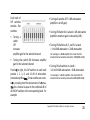
ENTERPRISE RECEPTION SOLUTION
Multi-Band Linear Amplifier
FORCE-5 5 Band Amplifier
Upl i nk Freq. Ra nge (MHz)
698-716/776-787/824-849/1710-1755 /1850-1910
Down Freq. Ra nge (MHz)
728-746/746-757/869-894/2110-2155/1930-1990
Supported Sta nda rds
CDMA, GSM, UMTS, WCDMA, HSPA(+), EVDO, EDGE, LTE
Ga i n Adjus tment Ra nge
31dB
Si gna l Ga i n
Depends On Model
Input/Output Impeda nce
50Ω
Noi s e Figure
5dB
VSWR
≤2.0
AC Power Tra ns former
110VAC,60Hz IN / 18VDC OUT
Ca bl e
CM400 or LMR400
Power Cons umption
<65W
Di mens i ons
14.5” x 11” x 3.5”
Wei ght
19.5 l b
This manual applies to all FORCE-5 models.
Cellphone-Mate, Inc.
FORCE-5 (07/12) v1.1
Patent Pending
Technical Support:
888.365.MATE (6283) phone
510.996.7250 fax
www.surecall.com
NOTICE: The manufacturer's rated output power of this equipment is for single-carrier operation. For situations when multiple carrier signals are present,
the rating must be reduced by 3.5 dB, especially where the output signal is reradiated and can cause interference to adjacent-band users.
This power reduction is to be by means of input power or gain reduction and not by an attenuator at the device output.
FORCE-5
User Manual
Table of Contents
---------------1
1.1 - Package Contents - - - - - - - - - - - - - - - - 1
1.2 - Features & Benefits - - - - - - - - - - - - - - - 2
-----------2
1.4 - How It Works - - - - - - - - - - - - - - - - - - - 3
1.5 - About This Manual - - - - - - - - - - - - - - 4
CHAPTER 2: Safety - - - - - - - - - - - - - - - - - - - - 5
2.1 - Safety Warnings 5 - - - - - - - - - - - - - - - - CHAPTER 3: Planning - - - - - - - - - - - - - - - - - - 7
3.1 - Overview - - - - - - - - - - - - - - - - - - - - - - 7
3.2 - Exterior Antenna - - - - - - - - - - - - - - - - - 8
3.3 - Interior Antennas - - - - - - - - - - - - - - - - 9
- - - - - - - - - - - - - 10
- - - - - - - - 13
- - - - - - - - - - - - - - - 14
3.7 - Accessories - - - - - - - - - - - - - - - - - - - - 15
- - - - - - - - - - - - - - - 16
- - - - - - - - - - - 16
- - - - - - - - - - - - - - - - - 16
4.3 - Exterior Antenna - - - - - - - - - - - - - - - - 16
4.4 - Internal Antennas - - - - - - - - - - - - - - - 17
- - - - - - - - - - - 19
- - - - - - 20
5.1 - DIP Switches and Lights - - - - - - - - - - - 20
- - - - - - - - - - - - - - 22
5.3 - Powering on the Amplifier - - - - - - - - - 22
- - - - - - - - - - - - - - - - - - - - - - - 24
- - - - - - - - - - - 24
- - - - - - - - - - - - - 25
CHAPTER 6: Warranty - - - - - - - - - - - - - - - - - 27
6.1 - Warranty Periods - - - - - - - - - - - - - - - - 27
- - - - - - - - - - - - 28
- - - - - - - - - - - - - 30
- - - - - - 31
- - - - - - - - - - - - - - - - - - - 31
Copyright 2012 Cellphone-Mate, Inc. All rights reserved.
i
Force-5(CM5000) Amplifier - Installa
Copyright & Trademark Informa
THIS MANUAL CONTAINS SAFETY, INSTALLATION, CONFIGURATION AND WARRANTY INFORMATION
FOR YOUR CELLPHONE-MATE, INC (CMI) AMPLIFIER. CMI RECOMMENDS THAT YOU SAVE THIS MANUAL IN A READILY ACCESSIBLE LOCATION IN CASE ANY QUESTIONS ARISE ABOUT THIS PRODUCT.
Copyright © 2012 by Cellphone-Mate, Inc. All rights reserved. SureCall is a registered trademark and
Cellphone-Mate is a trademark of Cellphone-Mate, Inc. All other trademarks or registered trademarks
ve owners.
are the property of their r
ii
Copyright 2012 Cellphone-Mate, Inc. All rights reserved.
CHAPTER 1: Introduction
This chapter introduces the Force-5
(CM5000) Amplifier and this manual.
Read this entire manual before
proceeding with the installation.
This manual applies to all Force-5
(CM5000) models.
1.1 - Package Contents
Your amplifier box contains the following items:
•
Force-5 (CM5000) amplifier.
•
Mounting kit (not shown).
•
DC power supply (not shown).
•
Wall anchors (not shown).
Copyright 2012 Cellphone-Mate, Inc. All rights reserved.
1
Force-5(CM5000) Amplifier - Installa
1.2 - Features & Benefits
The Force-5 amplifier offers the following features and benefits:
•
Powerful in-building amplifier with 31dB of
adjustable gain level.
•
Extends cellular signals in areas with poor coverage due to geographical loca
and/or
building design.
•
Suitable for large areas up to about 80,000
square feet depending on outside signal
strength and carrier frequency.
•
Sophis cated power control maintains maximum output power at 3 wa s EIRP.
•
Automa oscilla
det
and protecsystem powers down the amplifier to prevent harmful radio interference.
2
Copyright 2012 Cellphone-Mate, Inc. All rights reserved.
tems Needed
The Force-5 amplifier
requires the following
components for
a complete installa
• External antenna (such
at the CM288W omni
by Cellphone-Mate,
Inc.)
•
Lightning protector
(CMLP).
•
Cable spli er if installantennas.
ing
CHAPTER 1: Intr
•
•
Sufficient CM400 ultra
low loss interior/exterior cable of 50 ohm.
1.4 - How It Works
W
as the CM222W,
CM223 or CM224
and/or CM248W flat
panel by CellphoneMate, Inc.)
•
Grounded surge suppressor for DC power
supply.
The Force-5 amplifier boosts cellular signals from
the nearest tower to phones in a building and
from those phones back to the tower to compensate for weak r
caused by distance,
topography, building structure, and/or other reasons. The amplifier receives the signal from an
outside antenna, amplifies that signal, and then
rebroadcasts it via the interior antenna(s) where it
is picked up by cellular phones, modems, and data
cards. The interior antennas also pick up signals
from cellular devices and pass them to the amplifier. The amplifier boosts these signals and passes
them to the exterior antenna for rebroadcast back
to the tower.
W
Copyright 2012 Cellphone-Mate, Inc. All rights reserved.
3
Force-5(CM5000) Amplifier - Installa
1.5 - About This Manual
This manual contains the following informa
• Intr
This chapter introduces the
Force-5 amplifier and this manual.
• Safety: This chapter contains important safety
informa
• Planning: This chapter describes how to plan
your installa
for best results.
• Installa
This chapter describes how to
system.
install the amplifica
• Warranty: This chapter contains warranty
informa
for your amplifica
system.
This chapter contains
• Regulatory Informa
important regulatory agency informa
Lists of items or points to consider that need not
be performed in order appear in bullet format:
•
4
Item 1
• Item 2
Procedures that must be followed in a specific
order appear in numbered steps:
1. Perform this step first.
2. Perform this step second.
This manual also contains important safety informa
and ins
in specially forma ed
callouts with accompanying graphic symbols:
WARNING: WARNINGS INDICATE THE
POSSIBILITY OF PERSONAL INJURY.
CAUTION: WARNINGS INDICATE THE
POSSIBILITY OF EQUIPMENT DAMAGE
RADIO INTERFERENCE, ETC.
Note: Notes provide helpful inf
Copyright 2012 Cellphone-Mate, Inc. All rights reserved.
CHAPTER 2: Safety
This chapter contains important
safety information designed to prevent personal injury, equipment malfunction, and/or radio interference.
You are responsible for ensuring a
safe installation.
•
WARNING: FAILURE TO EXERCISE CAUTION WHEN WORKING IN HIGH AREAS
COULD CAUSE A FALL AND PERSONAL
INJURY.
2.1 - Safety Warnings
•
•
You are responsible for knowing and following
all applicable codes and regulations and for
obtaining all required permits and inspections.
Follow all safety precautions contained in this
Installation Manual.
The installation process may require working
in high locations such as roofs and/or ladders.
Follow applicable safety regulations and best
practices to avoid falling. Take care not to drop
objects off any high area. Cordon off ground
areas directly below roof or ladder work when
possible.
•
Always use appropriate personal protective
equipment such as goggles, gloves, hard hat,
etc. as needed and as required.
Copyright 2012 Cellphone-Mate, Inc. All rights reserved.
5
Force-5(CM5000) Amplifier - Installa
•
Some components may be heavy and/or
and carrying
bulky. Always use proper
techniques when handling components, especially when working on a ladder, roof, or other
area with a fall hazard.
when
determining the mounting location of the
•
rooftop donor antenna, look for any other
antennas that may be present and determine
what they are for. If there is any type of RF
enhancement system present in the building or
any carrier antennas on the roof a full spectrum
analysis will need to be performed before.
• Always use a properly installed CellphoneMate lightning protector between the exterior
antenna and the amplifier.
CAUTION: FAILURE TO PROPERLY
INSTALL A LIGHTNING PROTECTOR CAN
RESULT IN DAMAGE TO THE AMPLIFIER,
ANTENNAS, AND WIRING.
6
Copyright 2012 Cellphone-Mate, Inc. All rights reserved.
•
Always power off the amplifier before working
on the roof of the building or anywhere in
close proximity to the external antenna.
• Allow at least 24 inches (60cm) of separa
between interior antennas and humans or animals.
•
Allow at least 24 inches (60cm) of separa
between exterior antennas and all persons.
•
Comply with all antenna separa
ments to prevent signal oscilla
require-
CAUTION: SIGNAL OSCILLATION CAN
CAUSE RADIO INTERFERENCE WITH
CELLULAR TOWERS AND RESULT IN
CIVIL AND/OR CRIMINAL PENALTIES.
CHAPTER 3: Planning
This chapter describes how to plan
your amplifier installa
including
how to determine the best loca
for the inside and outside antennas.
3.1 - Overview
The general amplifier installa
these steps:
process follows
1. Decide where to mount the exterior antenna.
This will generally be on the wall or roof of the
with the strongest sigbuilding in the loca
nal. You will need to decide whether to use an
omnidir
antenna mounted v cally
or a Yagi directional antenna pointed at
the cellular tower (line of sight). You must
also consider attaching a grounded lightning
protector between the exterior antenna and
the amplifier.
2. Decide where to mount the interior
antenna(s), being sure to take separa
requirements into account. In general, long
narrow spaces will benefit most from direcflat-panel antennas while more square
spaces will benefit more from omnidir
dome antennas.
3. Decide where to mount the amplifier. This
near a
should be in a secure indoor loca
grounded power source.
Copyright 2012 Cellphone-Mate, Inc. All rights reserved.
7
Force-5(CM5000) Amplifier - Installa
4. Decide where to route the cables between the
exterior antenna and the amplifier and
between the amplifier and interior antennas.
5. Install the antennas as described in their
r
ve installa
6. Route the cables to the amplifier loca
7. Install the amplifier as described in this manual.
8. Power on the amplifier and perform the configura
and tes
as described in this
manual.
3.2 - Exterior Antenna
The exterior antenna and mast (if any) must be
that meets all of the followmounted in a loca
ing criteria:
You may use an omnidir
antenna such
as the CM288W (flat area with no obstructions)
transmits •
signals over a horizontal 360-degree circle.
8
Copyright 2012 Cellphone-Mate, Inc. All rights reserved.
Best signal strength.
CHAPTER 3: Planning
•
Not collocated with other antennas or used in
ntennas.
c
•
Away from all power lines.
•
6’ from lightning rod antennas.
•
24” from all persons.
provide a focused zone of coverage suitable for
long narrow areas. The following example uses
two dome antennas and one panel antenna to
provide full coverage.
These distances are general guidelines only; refer
to the applicable building and electrical codes in
your area to determine local requirements.
3.3 - Interior Antennas
You may use any combina
of omnidir
(dome) and/or dir
(flat panel) interior
signal
antennas needed to obtain op
strength throughout the building or installa
area. Dome antennas such as the CM222W,
CM223, and CM224 provide 360-degree
hemispherical coverage suitable for most square
areas while flat panel antennas such as the CM248W
Copyright 2012 Cellphone-Mate, Inc. All rights reserved.
9
Force-5(CM5000) Amplifier - Installa
Keep in mind that floor structures in
story
buildings can cause significant signal loss, which
means that you may need to install interior antennas on more than one floor. Here is an example of
story installa
Note: You may or may not need antenstory buildnas on every floor of a
ing depending on factors such as
building material, amplifier gain, etc.
10
Copyright 2012 Cellphone-Mate, Inc. All rights reserved.
3.4 - Antenna Separa
Proper antenna separa
is essen
in order to
(feedback) that can
prevent signal oscilla
is
interfere with the cellular tower. Separa
measured in a straight line from the exterior
antenna to the closest interior antenna. The closest allowable distance depends on a number of
factors such as amplifier gain level, building matestances are:
rial, etc. Recommended separa
Amplifier gain
40dB
45dB
50dB
55dB
65dB
70dB
75dB
80dB
Min. separation (ad)
5-6’
15-20’
50’
60’
75-80’
100’
100’-120’
120’-180’
CHAPTER 3: Planning
Note: Vertical separation is more important than horizontal separation. If you
are unable to obtain the required separation horizontally, try raising the exterior antenna. You may also try reducing
the amplifier gain as described in Chapter 5 of this manual.
The easiest way to calculate the straight-line separation between antennas is to break it down into
three simple measurements and then use some
basic geometry to find the distance, as follows:
1. Measure the distances ab, bc, and cd as
shown in the diagram on the next page.
-
Distance from the nearest interior antenna
(Point a) to the wall underneath the exterior antenna (Point b). This is distance ab.
-
Distance from Point b to directly underneath the exterior antenna. This is Point
(c). This is distance bc.
-
Distance from Point c to the exterior
antenna (Point d). This is distance cd.
2. Multiply ab times ab to obtain ab2.
3. Multiply bc times bc to obtain bc2.
4. Multiply cd times cd to obtain cd2.
5. Add ab2+bc2 to obtain ac2.
6. Add ac2+cd2 to obtain ad2.
Copyright 2012 Cellphone-Mate, Inc. All rights reserved.
11
Force-5(CM5000) Amplifier - Installation Manual
7. The straight-line distance ad is the square root
( ) of the result obtained in Step 6.
Note: Most calculators have a square
root ( ) key.
Example:
•
Distance ab=40 feet; ab2 = 40x40=1600.
•
Distance bc=10 feet; bc2 = 10x10=100.
•
Distance cd=20 feet; cd2 = 20x20=400.
•
ac2 = 1600+100=1700
•
ad2 = 1700+400=2100
•
ad = 45.83’
Here, the straight-line distance ad is just under 46
feet, which is compatible with 50dB amplifier gain
as indicated in the previous table.
12
Copyright 2012 Cellphone-Mate, Inc. All rights reserved.
Separate interior antennas based on the calculations shown in Section 3.5. You may mix and
match dome and directional antennas as needed
to obtain proper coverage throughout the building or area where you need to boost the signal.
If you are using a
Yagi exterior antenna, you should
normally aim it away
from all interior
antennas regardless
of separation to prevent oscillation.
CAUTION: SIGNAL OSCILLATION CAN
CAUSE RADIO INTERFERENCE WITH
CELLULAR TOWERS AND RESULT IN
CIVIL AND/OR CRIMINAL PENALTIES.
CHAPTER 3: Planning
3.5 - Calcula
rength
You can calculate the number of antennas you will
need using the following parameters (in dB):
•
•
Outside signal level (OSL): This is the signal
strength at the exterior antenna loca
and
will always be a nega ve number that will usually fall between -50 and -100dBm. Calls will
drop at levels of about -100dB and lower. A
system installed in an area where the signal is
-85 or worse will require some detailed enginOutside antenna gain (OAG): This the signal
boost provided by the exterior antenna and is
ve number with Cellphonealways a
Mate antennas.
OAG
CM288W omni
Gain
+3
Inside antenna gain (IAG): This is the signal
boost provided by an interior antenna and is
ve number with Cellphonealways a
Mate antennas.
IAG
Gain
CM222W omni dome
+3
+7
CM248W dir
panel
• Cable loss (CL): This is the signal loss caused
by the cable and is always a nega ve number.
•
CL
20’ CM400/CM240
30’ CM400/CM240
50’ CM400/CM240
100’ CM400/CM240
Copyright 2012 Cellphone-Mate, Inc. All rights reserved.
Loss
-1/-2
-2/-4
-3/-6
-4/-8
13
Force-5(CM5000) Amplifier - Installation Manual
•
Splitter loss (SL): This is the signal loss caused
by a splitter (used if you are installing multiple
antennas).
SL
2-way
3-way
4-way
•
Loss
-3
-5
-6
Amplifier gain (AG): Number of decibels of
amplification provided by the amplifier (rated
gain less any attenuation, as described in
Chapter 5 of this manual). This is always a positive number.
The signal strength S at an interior antenna equals
OSL+OAG+IAG+CL+SL+AG. To calculate the
approximate coverage distance of each antenna:
1. Calculate the signal strength S for the first
interior antenna using the preceding formula.
14
Copyright 2012 Cellphone-Mate, Inc. All rights reserved.
2. Find the signal strength S for the antenna
along the bottom of the graph on the following page.
3. Move straight up the signal strength line to
the PCS and cellular curves.
4. Read the approximate coverage radius on the
left.
3.6 - Amplifier Location
Select an indoor location for the amplifier that
meets the following criteria:
•
Wall or ceiling mounts are acceptable.
•
Near a properly grounded 110VAC outlet.
•
Not in a tightly enclosed or overly hot space.
•
All power and warning lights easily visible.
•
Least amount of cable to connect all antennas.
CHAPTER 3: Planning
3.7 - Accessories
The final step in the planning process is to make
sure you have all of the necessary accessories to
complete the installation. You will need all of the
items listed in Chapter 1 of this manual plus some
or all of the following:
•
Cable clips: Use these to secure the cables to
interior and exterior walls/ceilings.
•
Appropriately rated sealant/caulking: Use
this to waterproof the opening where the
cable from the exterior antenna enters the
building, if needed.
•
Hand and/or power tools: As needed to complete the installation.
•
Personal Protective Equipment (PPE): Use all
PPE required by local codes and/or best prac-
to help ensure personal safety during
installa
Note: You may need to obtain a permit
from your local building department to
install the amplifier and antennas.
Check your local building and/or electrical codes. You do not need any permits
from the FCC or the cellular carrier.
CAUTION: YOU ARE RESPONSIBLE FOR
ENSURING THAT THE INSTALLATION
MEETS ALL APPLICABLE CODES.
Copyright 2012 Cellphone-Mate, Inc. All rights reserved.
15
Force-5(CM5000) Amplifier - Installa
CHAPTER 4: Installation
This chapter describes how to install
the amplifier and antennas for best
results.
4.1 - Selecting the Locations
Select the locations for the exterior antenna, interior antenna(s), amplifier, cables, and accessories
as described in the previous chapter.
CAUTION: FAILURE TO PROPERLY PLAN
THE AMPLIFIER INSTALLATION CAN
CAUSE SIGNAL OSCILLATION AND/OR
OTHER EQUIPMENT MALFUNCTION.
16
Copyright 2012 Cellphone-Mate, Inc. All rights reserved.
4.2 - Soft Installation
Perform a “soft” installation of all components to
test signal coverage and oscillation before making
the installation permanent. Avoid making holes or
other permanent fixtures during this initial phase.
Please refer to Chapter 5 of this manual for configuration and testing instructions. Proceed with the
final installation once configuration and testing
are complete.
4.3 - Exterior Antenna
Mount the exterior antenna in the location you
selected during the planning process. Be sure to
follow all of the instructions included with the
antenna to ensure a safe installation. Remember:
•
An omnidir
antenna (CM288W , etc.)
must be mounted v cally.
•
A Yagi antenna (such as the CM230W) must be
mounted horizontally and be aimed at the
desired cellular tower (line of sight).
CAUTION: MOUNT THE EXTERIOR
ANTENNA ON A FIXED STRUCTURE .
WARNING: FAILURE TO EXERCISE CAUTION WHEN WORKING IN HIGH AREAS
COULD CAUSE A FALL AND PERSONAL
INJURY.
WARNING: DO NOT TOUCH ANY LIVE
ELECTRICAL WIRES OR ALLOW THE
ANTENNA OR CABLING TO TOUCH ANY
LIVE ELECTRICAL WIRES.
CAUTION: AVOID AIMING A YAGI
ANTENNA TOWARD ANY INTERIOR
ANTENNA .
1. Mount the antenna.
2. Connect a length of CM400 cable to the
hten un
ht.
ant
3. Run the cable along the planned route.
4. Install a properly grounded CMLP lightning
protector.
5. Seal any holes you make in the outside of the
building with appropriate caulking or sealant.
4.4 - Internal Antennas
Mount the interior antenna(s) in the loca
you selected during the planning process. Be sure
Copyright 2012 Cellphone-Mate, Inc. All rights reserved.
17
Force-5(CM5000) Amplifier - Installa
to follow the ins
included with the
Remember:
antenna(s) for a safe installa
•
Dome antennas (CM222W, CM223, etc.)
should be mounted in the ceiling as close to
the center of desired coverage area as possible
•
Flat panel antennas (CM248W) should be wallmounted as close as possible to center of the
wall at one end of long narrow space.
CAUTION: VERIFY THAT ALL INTERIOR
ANTENNAS MEET THE SEPARATION
REQUIREMENTS DESCRIBED IN THE
PREVIOUS CHAPTER AND THAT NO
ANTENNA IS AIMED TOWARD THE
EXTERIOR ANTENNA .
S.
18
Copyright 2012 Cellphone-Mate, Inc. All rights reserved.
LIVE
1. Mount
theELEC
antenna.
2. Connect a length of CM400 or CM240 cable to
hten un
ht.
the ant
antennas, run the
3. If you are installing
cable to the spli er loca
and connect the
cable to one of the outputs on the spli er.
4. Connect another length of CM400 or CM240
cable to the input side of the spli er (if used)
5. It is important to keep the cable runs equal or
use taps to ensure a harmonious install.
CAUTION: DO NOT CONNECT AN
INTERIOR ANTENNA TO THE SPLITTER
INPUT.
CHAPTER 4: Installa
4.5 - Moun
Mount the amplifier as follows:
4. Connect the exterior antenna cable to the
Outside Antenna port on the amplifier.
meets all of
1. Verify that the selected loca
the criteria described in the previous chapter.
5. Connect the interior antenna cable to the
Inside Antenna port on the amplifier.
kit to the ampli2. A ach the included moun
fier using the screws provided. Tighten the
screws by hand with a screwdriver un snug
plus 1/4 to 1/2 turn. Do not over hten.
6. Verify that all cable c
are snug and
that the exterior and interior antennas are
connected to the proper jacks.
3. Mount 24" x 24", 3/4" thick sheet of plywood
on top of sheetrock into wall studs where
amplifier is to be situated. Plywood should be
flush against wall. Once mounted, screw the
amplifier to plywood sheet. The top side of the
amplifier with the lights and DIP switches
should be facing away from the wall and be
plainly visible when standing near the amplifier.
CAUTION: DO NOT POWER ON THE
AMPLIFIER UNTIL INSTRUCTED TO DO
SO.
CAUTION: NEVER POWER ON THE
AMPLIFIER WHEN ANY ANTENNAS ARE
DISCONNECTED AS THIS COULD DAMAGE THE AMPLIFIER.
Copyright 2012 Cellphone-Mate, Inc. All rights reserved.
19
CHAPTER 5: Configura
Tes
This chapter describes how to power
on, configure, and test the amplifier.
(3) LTE (700MHz) DIP switches: These DIP
switches control LTE uplink (switches 10-6) and
downlink (switches 5-1) gain.
5.1 - DIP Switches and Lights
(4) Cellular (800MHz) DIP switches: These DIP
switches control cellular uplink (switches 10-6)
and downlink (switches 5-1) gain.
The Force-5(CM5000) amplifier has the following
DIP switches:
(1) AWS (2100MHz) DIP switches: These DIP
switches control AWS uplink (switches 1-5)
and downlink (switches 6-10) gain.
(2) PCS (1900MHz) DIP switches: These DIP
switches control PCS uplink (switches 1-5) and
downlink (switches 6-10) gain.
Copyright 2012 Cellphone-Mate, Inc. All rights reserved.
20
Each bank of
DIP switches
contains five
switches.
•
•
Turning a
switch
OFF
increases
amplifier gain for the selected channel.
Turning that switch ON decreases amplifier
gain for the selected channel.
From le to right, the DIP switches in each bank
provide 1, 2, 4, 8, and 16 dB of attenuation
(reduced amplifica
These switches are cumula ve, meaning that the total amount of a enuafor a channel is equal to the combined dB of
all ON DIP switches in the corresponding bank. For
example:
• Turning all switches OFF = 0dB attenuation
(amplifier is at full gain).
• Turning ON Switch #1 in a bank = 1dB attenuation
(amplifier maximum gain is reduced by 1dB ).
• Turning ON Switches #1, 3, and 5 in a bank
= 1+4+16dB attenuation = 21dB attenuation
For example, in a 80dB amplifier, this means that the
selected channel would be reduced to 59dB (80db-21db).
• Turning ON all switches in a bank =
1+2+4+8+16dB attenuation = 31dB attenuation
For example, in a 80 dB amplifier ,that means that the
selected channel would be reduced to 49dB (80dB-31dB).
Copyright 2012 Cellphone-Mate, Inc. All rights reserved.
21
Force-5(CM5000) Amplifier - Installa
The amplifier lights are as follows:
ra
By default, your amplifier ships with all DIP
switches turned OFF to provide maximum gain in
all channels. This should always be your st
point whenever installing or reinstalling the
amplifier.
5.3 - Powering on the Amplifier
When the amplifier is powered on:
•
The green Power light (5) should illuminate.
•
If any of the bands are oscillating, the
corresponding Band lights (6, 7, 8, 9, 10) will
flash red and that band will shut down. Note:
When the amplifier is turned on, the Band
lights will flash red and yellow for approx.
10 second.
22
Copyright 2012 Cellphone-Mate, Inc. All rights reserved.
To power on the amplifier:
1. Make sure that exterior and interior antenna
cables are snugly connected to the proper
ports on the amplifier.
2. Plug a surge suppressor into a grounded
110VAC wall outlet.
CHAPTER 5: Configura
Tes
3. Plug the AC end of the power adapter that
came with the amplifier into the surge suppressor.
4. Plug the DC end of the power adapter into the
Power port on the amplifier.
CAUTION: ONLY USE THE POWER SUPPLY INCLUDED WITH THE AMPLIFIER.
USE OF ANOTHER POWER SUPPLY
COULD DAMAGE THE AMPLIFIER AND/
OR POWER SUPPLY.
5. Verify that the green Power light is illuminated.
CAUTION: DO NOT PROCEED BEYOND
THIS POINT UNTIL THE AMPLIFIER IS
POWERED ON AND NO RED WARNING
LIGHTS ARE ILLUMINATED.
Copyright 2012 Cellphone-Mate, Inc. All rights reserved.
23
Force-5(CM5000) Amplifier - Installa
5.4 - Tes
•
Once the amplifier is powered on and no Warning
lights are illuminated, walk around the en re area
to test the voice and/or data signal. Refine the
antenna loca
and/or gain levels as needed,
and then complete the permanent installa
once the system is working as desired.
Do not expect to see 5 bars of r
everywhere in the building as this is pr cally
impossible. Also, signal strength in dB can vary
the
significantly without necessarily aff
number of bars displayed because different
phone and data card manufacturers handle
bars slightly differently.
•
A good rule of thumb is that increasing gain by
6dB doubles the coverage distance of the interior antennas. Start at the lowest gain se ng
and increase gain gradually as needed.
5.5 - Adjus
Keep the following points in mind when adjus
the amplifier:
•
24
Your
Full power is not always your best op
goal is to obtain a usable cellular signal in as
many areas of the building as possible. A sucmeans that you can make
cessful installa
calls without dropping and/or have a reliable
data c
Copyright 2012 Cellphone-Mate, Inc. All rights reserved.
• If one or more red Warning lights comes on,that
indicates that there's oscillation in that band and
the band will immediately shut down. If the dB
gain is not adjusted, the Warning light will
continue flashing. The amplifier will power down
and will then wake every 30 seconds for the next
15 minutes to see if the problem has been
resolved. If the problem has not been resolved with
CHAPTER 5: Configura
15 minutes, the amplifier will shut off and will
need to be unplugged and plugged back in
again to reset.
•
You may see oscilla
and/
•
If you can’t get the system to work properly,
interior
you may need to install an
antenna and/or a different type of interior
antenna and/or relocate interior antennas.
in the 800MHz band
Note: In general, the uplink and downlink DIP switches should be set iden
cally but this is not always the case.
5.6 - Automa
Tes
tdown
If equipped, the Force-5 amplifier includes an
automa shutdown feature that works in the following sequence:
1.
2.
and/or downlink, the appropriate Warning
light(s) will begin flashing red and the Power
light (light 5 in the diagram on Page 21)
remains green.
and/or 7, 8, 9, and 10 will blink as appropriate
3. If the electrical current powering the amplifier
is too weak or too strong, lights 6 and/or 7, 8,
9,10 will blink yellow.
Copyright 2012 Cellphone-Mate, Inc. All rights reserved.
25
Force-5(CM5000) Amplifier - Install
4. If the problem is not resolved, the affected side
will shut down for 30 seconds.
5. The amplifier will wake back up. When this
occurs, the power light will be green. If oscillaresumes, the lights will flash as previously
described. These 30-second cycles will confor 15 minutes or un the problem is
resolved.
6. If the problem is not resolved within 15 minutes,
the amplifier will shut down (all lights off except
the Power light, which is green) and must be reset
by unplugging it from the power supply and
plugging it back in.
To resolve oscilla
increase the antenna sepa3.4) and/or the a enua
(Secra
26
Copyright 2012 Cellphone-Mate, Inc. All rights reserved.
7. Each band on the amplifier works
independently from other bands. Therefore,
Band lights will react accordingly.
CHAPTER 6: Warranty
This chapter contains the warranty
information for your CELLPHONEMATE product and also contains
information on how to contact the
company.
6.1 - Warranty Periods
Your warranty includes the following periods:
•
Two-Year Product Warranty: CELLPHONEMATE products are covered under a two-year
product warranty from the date of purchase.
This protects the customer from any defects
or problems the product may have that are
solely the fault of CELLPHONE-MATE Inc.
Incorrect installation or misuse will void this
warranty. Upon the return of a defective product, CELLPHONE-MATE will issue the customer
a working replacement. All returned packages
should contain all products distributed.
•
Five-Year Extended Product Warranty: A five
year warranty is available for purchase on any
products sold by CELLPHONE-MATE Inc. A fiveyear warranty must be obtained at the time of
purchase. This warranty adds an additional
three years to the two year warranty we provide. All regulations still apply.
Copyright 2012 Cellphone-Mate, Inc. All rights reserved.
27
Force-5(CM5000) Amplifier - Installa
6.2 - Warranty Informa
1. CELLPHONE-MATE, Inc. warrants to the Buyer
that each of its products will be free from
defects in material and workmanship and will
perform in full accordance with applicable
specifica
when shipped. The limit of liability under this warranty is, at CELLPHONEto repair or replace any
MATE, Inc.’s op
product or part thereof which shall, within
TWO YEARS of purchase as determined by
examina
by CELLPHONE-MATE, Inc., prove
def ve in material and/or workmanship.
Warranty returns must first be authorized in
by CELLPHONE-MATE, Inc. Disassembly
of any CELLPHONE-MATE, Inc. product by anyone other than an authorized representa ve
of CELLPHONE-MATE, Inc. voids this warranty
in its en rety. CELLPHONE-MATE, Inc. reserves
the right to make changes in any of its prod-
28
Copyright 2012 Cellphone-Mate, Inc. All rights reserved.
to make
ucts without incurring any obliga
the same changes on previously delivered
products.
of the warran
provided for
2. As a c
herein, the Buyer will prepay the shipping
charges for all products returned to CELLPHONE-MATE, Inc. for repair and CELLPHONEMATE, Inc. will pay the return shipping with
the ex
of product returned from outside the United States, in which case the Buyer
will pay all shipping charges.
3. The Buyer will pay the cost of
and
any goods returned under the wartes
ranty or otherwise which are found to meet
or which are not
the applicable specifica
def ve or not covered by this warranty.
4. Products sold by CELLPHONE-MATE, Inc. shall
not be considered def ve or non-conform-
CHAPTER 6: Warranty
ing to the Buyer’s order if they satisfactorily
fulfill the performance requirements that
were published in the product specification literature, or in accordance with samples provided by CELLPHONE-MATE, Inc. This warranty
shall not apply to any products or parts
thereof which have been subject to accident,
negligence, alteration, abuse, or misuse. CELLPHONE-MATE, Inc. makes no warranty whatsoever in respect to accessories or parts not
supplied by it.
5. Limitations of Warranty, Damages and Liability: EXCEPT AS EXPRESSLY SET FORTH HEREIN,
THERE ARE NO WARRANTIES, CONDITIONS,
GUARANTEES OR REPRESENTATIONS AS TO
MERCHANTABILITY, FITNESS FOR A PARTICULAR PURPOSE OR OTHER WARRANTIES, CONDITIONS,
GUARANTEES
OR
REPRESENTATIONS, WHETHER EXPRESSED OR
IMPLIED, IN LAW OR IN FACT, ORAL OR IN
WRITING. CELLPHONE-MATE, INC.’S AGGREGATE LIABILITY IN DAMAGES OR OTHERWISE
SHALL NOT EXCEED THE PAYMENT, IF ANY,
RECEIVED BY CELLPHONE-MATE, INC. FOR THE
UNIT OF PRODUCT OR SERVICE FURNISHED
OR TO BE FURNISHED, AS THE CASE MAY BE,
WHICH IS THE SUBJECT OF CLAIM OR DISPUTE. IN NO EVENT SHALL CELLPHONE-MATE,
INC. BE LIABLE FOR INCIDENTAL, CONSEQUENTIAL, OR SPECIAL DAMAGES, HOWSOEVER
CAUSED.
6. All matters regarding this warranty shall be
interpreted in accordance with the laws of the
State of California and any controversy that
cannot be settled directly shall be settled by
arbitration in California in accordance with the
rules then prevailing of the American Arbitration Association, and judgment upon the
Copyright 2012 Cellphone-Mate, Inc. All rights reserved.
29
Force-5(CM5000) Amplifier - Installa
award rendered may be entered in any court
reof.
ha
7. If one or more provisions provided herein are
held to be invalid or unenforceable under
applicable law, then such provision shall be
ineff ve and excluded to the extent of such
invalidity or unenforceability without aff
in any way the remaining provisions herein.
6.3 - Contact Informa
You may consult a Cellphone-Mate, Inc. customer
follows:
service agent directly by cont
•
View the list of Frequently Asked Ques
(FAQ) online at h p://www.surecall.com/
•
Our online support center is at h p://cellket.html. If needed, you
phone-mate.c
can create an online support ket. This is the
fastest and best way to get support for your
product.
•
Write to the address on the web site or call
the phone number on the back cover of this
manual.
8. CELLPHONE-MATE reserves the right to bill for
labor spent on equipment where there is no
def ve found
9. All items that are out of warranty are subject
reight charges.
to a repair f
10. Def ve items in warranty will be repaired at
charge and will be returned with
no
freight paid by CELLPHONE-MATE.
30
Copyright 2012 Cellphone-Mate, Inc. All rights reserved.
CHAPTER 7: Regulatory Information
This chapter contains the regulatory
information for the FCC (USA) and
Industry Canada (Canada).
7.1 - FCC Information
FCC ID: RSNCM5000
Warning: Changes or modifications to this device
not expressly approved by Cellphone-Mate, Inc.
could void the user’s authority to operate the
equipment.
Note: This equipment has been tested and found
to comply with the limits pursuant to Parts 22 and
24 of the FCC Rules. These limits are designed to
provide reasonable protection against harmful
interference in a residential installation. This
equipment generates, uses, and can radiate radio
frequency energy and, if not installed and used in
accordance with the instructions, may cause
harmful interference to radio communications.
However, there is no guarantee that interference
will not occur in a particular installation. If the
equipment does cause harmful interference to
radio or television reception, which can be determined by turning the equipment off and on, the
user is encouraged to try to correct the interference by one or more of the following measures:
•
Reorient or relocate the receiving antenna.
•
Increase the separation between the equipment and receiver.
Copyright 2012 Cellphone-Mate, Inc. All rights reserved.
31
Force-5(CM5000) Amplifier - Installa
•
Connect the equipment to an outlet on a circuit different from that to which the receiver
is connected.
•
Consult the dealer or an experienced radio/TV
technician for help.
This equipment complies with FCC radia
exposure limits set forth for an uncontrolled environment. This transmi er must not be co-located or
opera
in c
with any other antenna
or transmi er. In accordance with FCC requirements of human exposure to radio frequency
element (antenna) shall be
fields, the radia
installed such that a minimum separa
distance
of 25cm (11in) is maintained from all persons.
32
Copyright 2012 Cellphone-Mate, Inc. All rights reserved.