1
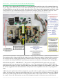
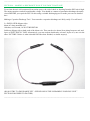
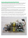
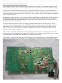
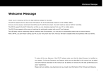
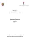
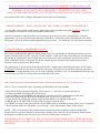
------------------------------------------------------------------------------------------------------------------------------------THIS IS A GUIDE ON REPAIRING YOUR BEYONWIZ IP-100 MODEL POWER SUPPLY UNIT
WARNING – IF YOU HAVE ANY OTHER MODEL – DO NOT FOLLOW THIS GUIDE
EMAIL ME FOR FURTHER ASSISTANCE (SEE REVISION HISTORY FOR CONTACT DETAILS)
Last updated 28/01/2013 (Changes and updates listed in the revision history)
------------------------------------------------------------------------------------------------------------------------------------** BRAND WARNING – DON’T USE SUNTAN CAPACITORS TO COMPLETE THIS REPAIR **
...Or any other cheap brand for that matter. Please ensure that you follow this guide carefully, it tells you
which brands to use and even lists part numbers further down.
Your local electronics enthusiast shops are not always a good place to source "good quality" electronic
components. Try a more professional outlet such as Element 14 (Farnell) or RS Components or even XON
Electronics. All can be ordered online and delivered to your door - it is worth the few extra days in delivery!
------------------------------------------------------------------------------------------------------------------------------------** REPAIR THREAD - AMMENDMENT NOTE **
The works contained in this guide are based purely on my own knowledge of repairing this model of power
supply combined with 20 years’ experience in the industry. As the age of these units increases, and therefore
the amount of running time each machine has received increases, new components may be discovered as
faulty. When this occurs I will update the guide to detail any new possible issues and resolutions that
Beyonwiz owners may need to know about.
This repair guide is for the newer model Beyonwiz PSU’s found many of the Beyonwiz units. It will require
AT LEAST 2 HOURS of your time to complete it properly. The repair is not just about replacing capacitors,
there is more to it than that and I urge you to read it carefully and follow ALL recommendations along the way
to ensure that your PSU is working correctly at the end of the repair.
------------------------------------------------------------------------------------------------------------------------------------Why would you want to attempt to do this repair? (Besides the fact that you love your Beyonwiz)…
Here is a list of reasons that *may* be getting you frustrated with your machine.
* HDD checks being performed regularly for no reason, i.e., each time you power the unit on
* Unstable operation, boot failure & system lockup
* Lost recordings & corrupt HDD (this can also be caused by the SATA cable which can fail also)
* HDD isn’t detected by the BW but the HDD has tested ok in a PC or other PVR
* Colour distortion & abnormal looking output through HDMI or no HDMI output at all
* ERROR 0000 or E:BOOTING on system start-up (most common fault)
* No DISPLAY on the front of the machine but the HDD spins up immediately when mains power is supplied.
* Wired network failure & USB failure (very bad sign – stop using machine ASAP if this occurs)
NOTE – This is a broad list of the common failures for the Beyonwiz machines using this model PSU.
Failures however are NOT limited to this list only and other issues may also be experienced. If this sounds
familiar then it might be time for you to give your beloved Beyonwiz a makeover.
THIS MODEL PSU IS CURRENTLY ONLY FOUND IN THE BEYONWIZ DP-P2. THERE ARE MORE
REPAIR GUIDES AVAILABLE ON THE BEYONWIZ FORUM FOR OTHER MODELS OF BEYONWIZ
MACHINES.
-------------------------------------------------------------------------------------------------------------------------------------
------------------------------------------------------------------------------------------------------------------------------------TABLE OF CONTENTS
SECTION 1 - DISCLAIMER & GENERAL WARNING - READ BEFORE YOU BEGIN
SECTION 2 - GENERAL ASSUMPTIONS, INFORMATION AND TOOLS REQUIRED FOR THE JOB
SECTION 3 - AN OVERVIEW OF THE WORK REQUIRED
SECTION 4 - MAKING A DISCHARGE TOOL IF YOU DON’T HAVE ONE
SECTION 5 - REMOVAL OF THE PSU UNIT FROM YOUR BEYONWIZ
SECTION 6 - REPAIRING YOUR PSU UNIT
SECTION 7 - RE-ASSEMBLING YOUR BEYONWIZ
SECTION 8 - TESTING AND FINAL NOTES
SECTION 9 - REVISION HISTORY
------------------------------------------------------------------------------------------------------------------------------------SECTION 1 - DISCLAIMER & GENERAL WARNING - READ BEFORE YOU BEGIN
I TAKE NO RESPONSIBILITY FOR WHAT YOU MAY DO TO YOUR OWN PSU OR PVR. THIS
REPAIR IS PROVIDED FOR GUIDANCE ONLY AND IS INTENDED FOR EXPERIENCED USERS
WITH ELECTRONICS KNOWLEDGE.
DO NOT ATTEMPT TO REPAIR A 240v PSU UNLESS YOU KNOW WHAT YOU ARE DOING!
IF YOU ARE ATTEMPTING SOMETHING LIKE THIS FOR THE FIRST TIME – THINK TWICE AND
THEN THINK AGAIN!
THIS PSU WILL STILL CONTAIN VERY HIGH VOLTAGE EVEN WHEN DISCONNECTED.
THE HIGH VOLTAGE SIDE OF THE PSU RUNS AT AROUND 350v – MUCH HIGHER THAN 240v
ONCE CONVERTED TO DC VOLTAGE – STAY AWARE AT ALL TIMES.
------------------------------------------------------------------------------------------------------------------------------------SECTION 2 – GENERAL ASSUMPTIONS, INFORMATION AND TOOLS REQUIRED FOR THE JOB
To begin, I have made some basic assumptions, if you are contemplating this repair, then…
Firstly, I imaging you must own the basic equipment or can at least get it…
Secondly, you know something about electronics and are aware of what a capacitor or diode is…
Lastly, you are familiar with removing and installing electronic components…
If you fail on any of these points you should turn back now. Feel free to contact me and I can arrange to assist
you with the repairs. (See revision history below for ways to contact me).
Equipment you will need for the repair...
A 25w Soldering Iron or Temperature Controlled Iron (Set to a temperature of no more than 400°)
Good Quality Solder & De-Soldering Braid or Solder Removal Tool
Discharge Tool (Instructions a little further down)
Wire Cutters & A Philips Screw Driver
Do not use a soldering iron that is TOO HOT as you can severely damage the PCB and/or other components.
Equally, do not use anything less than 25w (i.e. 15w) as the negative tracks that you will be soldering are
wide, and cover a considerable part of the PCB in the area you are working on. They will take a bit of heat to
melt and replace the solder in a clean and appropriate way. Considerable frustration will occur if you use a
soldering iron that is TOO LOW in temperature.
-------------------------------------------------------------------------------------------------------------------------------------
------------------------------------------------------------------------------------------------------------------------------------SECTION 3 - AN OVERVIEW OF THE WORK REQUIRED
PICTURE 1 below displays the EIGHTEEN (18) components that should be replaced for continued longevity
of your PSU. I have shown a picture of the PSU with all affected parts removed and marked on the photo with
18 short RED lines so you can see visually where they all are. The values of the components listed on the right
of the picture are my recommended values for replacement, PLEASE STICK TO THESE VALUES. I have
provided part numbers and suppliers further down so you can order EXACTLY what you need.
The capacitors above relate to and filter the many power rails of the power supply. Sometimes these capacitors
are raised up and are swollen/split at the top or bottom, but this is NOT ALWAYS the case, and if yours are
not swollen, it definitely DOES NOT mean that your capacitors are therefore ok. Replace them all regardless.
PLEASE ALSO NOTE – IMPORTANT – This repair is a ONE SIZE FITS ALL repair, and covers ALL
components that I have encountered as faulty (bar one – rare). The components all relate to MANY different
faults and one day when I get time I will list which parts cause which symptom. In the meantime, replace them
all with my suggested values and brands below and you won’t have any further issues for a very long time to
come.
Additional to the replacement of these components, you will need to re-solder many of your PCB solder joints
as they will by now have started to crack and become “dry” so to speak. You will need to inspect the PCB and
look for poor solder joints with obvious cracking on them. There is ALWAYS at least 20 – 30 of them when I
do a repair. If you can’t find any then you are not looking hard enough. I will go into more on this later on.
-------------------------------------------------------------------------------------------------------------------------------------
------------------------------------------------------------------------------------------------------------------------------------SECTION 4 – MAKING A DISCHARGE TOOL IF YOU DON’T HAVE ONE
Even when the unit is disconnected from mains power, the risk of shock or shorting from the PSU unit is high.
The mains capacitor can hold considerable voltage. You should as a matter of precaution discharge the mains
circuit BEFORE you repair the PSU. Do this using a suitable discharging tool or make your own as detailed
here.
Making a Capacitor Discharge Tool - You can make a capacitor discharge tool fairly easily. You will need…
2 x INSULATED alligator clips
40cm of 14awg stranded wire
10k ohm, wire-wound, 10 WATT RESISTOR
Solder an alligator clip to both ends of the 40cm wire. Then cut the wire about 18cm along from one end, and
layers of ELECTRICAL TAPE. Alternatively, you can use heat shrink tube, at least 2 layers of it, one over the
other. PICTURE 2 below is what it should look like when finished, or similar anyway!
(DO NOT TRY TO DISCHARGE YET - SEE BELOW IN THE “REPAIRING YOUR PSU UNIT”
SECTION FOR WHEN TO DO THIS)
------------------------------------------------------------------------------------------------------------------------------------
------------------------------------------------------------------------------------------------------------------------------------SECTION 5 – REMOVAL OF THE PSU UNIT FROM YOUR BEYONWIZ
1. REMOVE POWER FROM THE BEYONWIZ MACHINE, ensure that the power cable is unplugged, not
just turned off. This sounds like the most obvious point doesn’t it, but surprisingly it isn’t!!! Wait at least 1
hour after removing power before continuing with the repair, to allow the unit to fully cool down.
2. Unscrew and remove the TWO (2) side case screws and FOUR (4) rear case screws from your unit and
remove the lid by sliding it back and then lift it upwards.
3. Disconnect the mains voltage power connector from the PSU. To remove this you will need to push the
connector lock in as you pull it up and off the board. (Top left connector in PICTURE 1). Refer to POINT 1
above before doing this!
4. Disconnect the BW mainboard power cable FROM THE MAINBOARD – this cable is NOT removable
from the PSU. To remove it off the mainboard, push the connector lock in as you pull it up and off. MAKE
SURE YOU PUSH THE CLIP/LOCK IN – I have seen what happens to a mainboard when you don’t.
5. Disconnect the HDD power cable FROM THE HDD – this cable is NOT removable from the PSU. It
simply pulls out of the back of the HDD, but gently or you can crack the HDD casing/connector.
6. Unscrew and remove the FOUR (4) screws holding the PSU in place and lift the PSU up and out of the BW
case by its edges being sure to avoid touching any components, it will still contain stored voltage at this time.
You should now be staring at your power supply. It “should” look something like PICTURE 3 below.
-------------------------------------------------------------------------------------------------------------------------------------
-----------------------------------------------------------------------------------------------------------------------------------SECTION 6 – REPAIRING YOUR PSU UNIT
If you carefully turn your PSU over and look at the solder side of the PCB, you can familiarise yourself with
where the points are that you will need to unsolder which I have marked for you. Refer to PICTURE 4 below.
At this point you should DISCHARGE any stored voltage from the mains capacitor. As mentioned already,
the stored voltage here can cause you big problems, least of all would be shorting/sparking the unit, and worst
would be hurting yourself considerably. See SECTION 3 above for more information on making a discharging
tool if you do not have one.
Discharging the mains capacitor – The capacitor that will need discharging is the BIG 400v mains capacitor on
the HIGH VOLTAGE side of the PCB. If you have followed the instructions this far, then your unit will be
off, disassembled and you should be staring at the solder side of your power supply PCB. If not, go back up
and follow the previous instructions.
Carefully connect the alligator clips to the capacitor terminals/solder points on the PCB (one clip to each
exposed terminal, don’t short them!). Look at PICTURE 4 below for the location of the BIG 400v capacitor
solder points, I have marked them in YELLOW. Once attached, the resistor will drop the voltage down in
around a minute or so, count to 90 slowly and then unclip and you’re done. Test using a multimeter if you
have one to ensure that the voltage is nil.
Now it's time to replace the components on the board. You will need to replace 18 components in total. The
voltage and type of each component is detailed in PICTURE 1 above and with more detail below where I have
provided MANUFACTURER PART NUMBERS for ordering replacements.
In PICTURE 4, you can see the underside of the PSU board, and as mentioned above I have marked the points
you will need to unsolder, they are in RED – they will match the components marked on PICTURE 1 above.
Below are the PCB PART NUMBERS to replace and also a RECOMMENDED REPLACEMENT for each.
(All replacements listed below have been specifically selected for their quality, SIZE and suitability)
PURCHASE EVERYTHING BELOW FROM ELEMENT 14 OR RS COMPONENTS
(DO NOT SUBSTITUE THESE – THEY ARE LISTED FOR A REASON – BEST PARTS TO USE FOR THE JOB)
D2, D4 - SF14 DIODE 200V ULTRA-FAST
REPLACEMENT USE “VISHAY UF4003 DIODE”
** THIS IS NOT THE SAME AS A 1N4003 POWER DIODE SO DO NOT SUBSTITUTE
D11, D12, D13 - UF5402 DIODE 200V ULTRA-FAST (REV 3 PSU AND EARLIER ONLY – SEE BELOW)
REPLACEMENT USE “VISHAY UF5404 DIODE”
** THIS IS NOT THE SAME AS A 1N5404 POWER DIODE SO DO NOT SUBSTITUTE
C7 - 33uf 50v
REPLACEMENT NICHICON PW SERIES P/N: UPW1H330MED1TD
C15, C17, C27, C30 - 330uf 25v
REPLACEMENT PANASONIC FR SERIES P/N: EEUFR1E331
-
-
33uf 50v
330uf 25v
C36 - 680uf 10v
REPLACEMENT PANASONIC FR SERIES P/N: EEUFR1C681L
-
680uf 16v
C26, C28, C29 - 1000uf 25v
REPLACEMENT PANASONIC FR SERIES P/N: EEUFR1E102L
-
1000uf 25v
C23, C25 - 2200uf 10v
REPLACEMENT PANASONIC FR SERIES P/N: EEUFR1A222L
-
2200uf 10v
C22, C24 - 3300uf 10v
REPLACEMENT PANASONIC FM SERIES P/N: EEUFM1A332
-
3300uf 10v
PLEASE NOTE – the 3 diodes D11, D12, D13 are only found in REV 3 or EARLIER PSU’s. If you have a
REV 4 PSU (DP-P2 1TB & 2TB), then EVERTHING STILL APPLIES except for the 3 DIODES mentioned.
Unsolder and remove the old components one at a time and then use solder braid to clean off any solder left on
the PCB solder pad. This will then leave you a nice clean, unblocked hole (2 of them for each component) for
which you can then drop in your new component and line it up before soldering it in permanently. Ensure that
each component is installed around the right way, as EVERY COMPONENT you are working with is
polarised so DO NOT INSTALL THEM AROUND THE WRONG WAY (more notes on this 2 paragraphs
down). Once you have soldered each into place, remove the excess wire/leg of the components using wire
cutters, they should be cut flush with the solder pad, as per all other joints on the PCB. Please note how the 3
diodes D11, D12, D13 are sitting about 1cm above the PCB, and ensure that you install the 3 replacements in
the same way.
Now assuming everything went well in replacing the 18 components, now what? Clean the flux off your board
with Turps or flux/PCB cleaner so that you can see the board clearly. Then get a nice white bright lamp or
torch and inspect your PCB. There will almost certainly be a LOT of dry joints on your PSU, especially
around the middle of the low voltage side, and in the high voltage area too. They should be easy to identify.
Spend the time and MAKE SURE you go over them properly, ensuring you don’t short any of the joints out
with other joints on the board. It can sometimes be really hard to resolder the joints properly as there is a
protective lacquer coating over the board which makes it pretty hard for the solder to stick. Scraping the
affected legs with a blade BEFORE soldering them helps to make the solder stick better if need be.
So let’s check where we are at now and make sure the workmanship is up to scratch… Double Check and
triple check that you have installed the 18 components around the correct way, as mentioned they are all
polarised and must be installed correctly. The – (or negative) of the capacitors is marked on the side of the
capacitor as well as on the PCB board. The Anode and Cathode of the diodes is also marked with a band/line
on the diode and on the PCB as well so MAKE SURE EVERYTHING IS AROUND THE RIGHT WAY.
Double check the rest of your work (especially dry joints) as a safe guard before proceeding. Everything ok?
So the caps are installed correctly… the diodes are around the right way… all the obvious dry joints have been
resoldered nicely… NO SHORTING (double check that too)… Basically you’re itching to get it back into the
machine right??? Ok, go for it, that’s pretty much the repair done!
Perhaps just one final check…All good? (Yes I’m Paranoid…)
Ok, time to reinstall so keep reading.
------------------------------------------------------------------------------------------------------------------------------------SECTION 7 – REASSEMBLING YOUR BEYONWIZ
To RE-ASSEMBLE your PSU unit into your Beyonwiz…
1. Place the PSU back into its proper home, make sure the cables are not caught underneath, line it up so that
the FOUR (4) screw holes are aligned to the case mounts, then replace the screws you took out and secure the
PSU.
2. Connect the Hard drive power cable back into the HDD.
3. Reconnect the BW mainboard power cable to the mainboard. Line it up and push down, it should click into
place and will not fit on properly the wrong way around.
5. Check to make sure the SATA cable is still pushed in tight in both the hard drive & mainboard, sometimes
it can work loose.
6. Reconnect the mains power cable to the PSU. Line it up and push down, it should click into place.
That’s it. You’re basically ready to go. Do not replace the lid just yet, do some testing first.
------------------------------------------------------------------------------------------------------------------------------------SECTION 8 – TESTING AND FINAL NOTES
Before replacing the lid and installing your unit back into its permanent home, test it for power and function.
A basic test would be to turn it on and check for standby power. At this point power the wiz up and check that
the unit goes from standby to “on”, and then check that the HDD powers up, and that you have output to a
TV/monitor. If that’s all good, then you can do further functionality tests whenever you are ready. Depending
on how bad your PSU was, you may well need to format your Hard Drive, this is quite normal, and at the very
least you may need to do a HDD Check, this does not mean your PSU is still faulty.
There is also every possibility you MAY need to REPLACE the SATA cable as well and there is no time like
now to do it being that the wiz is open. They tend to fail a fair bit.
Ok, Now that you have… completed your testing, are happy with the result and all features are working well you can relax, put the lid back on and replace the 6 case screws, job done! The cost apparently of replacing
this PSU with a new one from Beyonwiz was upwards of $150+ excluding delivery or labour to fit it (not sure
of the current price if they are even available that is). This repair should cost you no more than $25 - $30 in
components plus maybe a bit for delivery if you order them online and of course the cost of your time too!
To anyone that would like me to do it for them, I can do… for a very low and reasonable amount, which varies
on how bad your PSU is, as it takes a LONG TIME to repair these units properly. (See revision history below
for ways to contact me). I do not repair these for the money / profit as anyone who has used me would know.
I hope this assists many users with extending the life of their units!
-------------------------------------------------------------------------------------------------------------------------------------
------------------------------------------------------------------------------------------------------------------------------------SECTION 9 – REVISION HISTORY
Version Changes & Updates…
1.0 - (28/01/2013)
Initial write up - 4 pictures included
Made into a downloadable PDF version - Download it from the link below.
For repair assistance with this or other BEYONWIZ models - please visit my web site www.decisivecomputersolutions.com.au/service.html or contact me through the messaging system of this
forum.
Found an error or omission? Please let me know. I am far from perfect, so if you see something, please tell me
through a PM on the forum or via email so it can be fixed. Thanks.
-------------------------------------------------------------------------------------------------------------------------------------