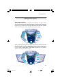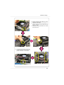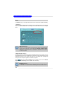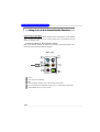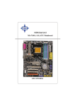
1
915GM Speedster
MS-9625 (v1.X) Workstation Board
English Version
G52-S9625X1
i
9625v1.0-Preface.p65
1
2005/8/4, 下午 02:36
Copyright Notice
T he material in this doc ument is the intellec tual property of M ICRO-STAR
INTERNATIONAL. We take every care in the preparation of this document, but no
guarantee is given as to the correctness of its contents. Our products are under
continual improvement and we reserve the right to make changes without notice.
Trademarks
All trademarks are the properties of their respective owners.
Intel® and Pentium® are registered trademarks of Intel Corporation.
AMD, Athlon™, Athlon™ XP, Thoroughbred™, and Duron™ are registered trademarks of AMD Corporation.
PS/2 and OS ® /2 are registered trademarks of International Business Machines
Corporation.
W indows ® 95/98/2000/NT/XP are registered trademarks of Microsoft Corporation.
Netware® is a registered trademark of Novell, Inc.
Award® is a registered trademark of Phoenix Technologies Ltd.
AMI® is a registered trademark of American Megatrends Inc.
Revision History
Revision
Revision History
Date
V1.0
First release
August 2005
Technical Support
If a problem arises with your system and no solution can be obtained from the user’s
manual, please contact your place of purchase or local distributor. Alternatively,
please try the following help resources for further guidance.
Visit the MSI website for FAQ, technical guide, BIOS updates, driver updates,
and other information: http://www.msi.com.tw/program/service/faq/
faq/esc_faq_list.php
Contact our technical staff at: [email protected]
ii
9625v1.0-Preface.p65
2
2005/8/4, 下午 02:36
Safety Instructions
1.
Always read the safety instructions carefully.
2.
Keep this User’s Manual for future reference.
3.
Keep this equipment away from humidity.
4.
Lay this equipment on a reliable flat surface before setting it up.
5.
The openings on the enclosure are for air convection hence protects the equipment from overheating. DO NOT COVER THE OPENINGS.
6.
Make sure the voltage of the power source and adjust properly 110/220V before connecting the equipment to the power inlet.
7.
Place the power cord such a way that people can not step on it. Do not place
anything over the power cord.
8.
Always Unplug the Power Cord before inserting any add-on card or module.
9.
All cautions and warnings on the equipment should be noted.
10. Never pour any liquid into the opening that could damage or cause electrical
shock.
11. If any of the following situations arises, get the equipment checked by a service
personnel:
†
†
†
†
The power cord or plug is damaged.
Liquid has penetrated into the equipment.
The equipment has been exposed to moisture.
The equipment has not work well or you can not get it work according to
User’s Manual.
† The equipment has dropped and damaged.
† The equipment has obvious sign of breakage.
12. DO NOT LEAVE THIS EQUIPMENT IN AN ENVIRONMENT UNCONDITIONED, STORAGE TEMPERATURE ABOVE 600 C (1400F), IT MAY DAMAGE THE EQUIPMENT.
CAUT ION: Danger of expl os i on if bat ter y i s i nc orrec tl y r epl ac ed.
Replac e only with the same or equivalent type rec ommended by the
manufacturer.
iii
9625v1.0-Preface.p65
3
2005/8/4, 下午 02:36
FCC-B Radio Frequency Interference Statement
T h is eq uip men t h as been
tested and found to c omply
with the limits for a Class B
digital device, pursuant to Part
15 of the FCC Rules. These limits are designed to provide reasonable protection
against harmful interference in a residential installation. This equipment generates,
uses and can radiate radio frequency energy and, if not installed and used in accordance with the instructions, may cause harmful interference to radio communications.
However, there is no guarantee that interference will not occur in a particular
installation. If this equipment does cause harmful interference to radio or television
reception, which can be determined by turning the equipment off and on, the user is
encouraged to try to correct the interference by one or more of the measures listed
below.
† Reorient or relocate the receiving antenna.
† Increase the separation between the equipment and receiver.
† Connect the equipment into an outlet on a circuit different from that to
which the receiver is connected.
† Consult the dealer or an experienced radio/television technician for help.
Notice 1
The changes or modifications not expressly approved by the party responsible for
compliance could void the user’s authority to operate the equipment.
Notice 2
Shielded interface cables and A.C. power cord, if any, must be used in order to
comply with the emission limits.
VOIR LA NOTICE D’INSTALLATION AVANT DE RACCORDER AU RESEAU.
Micro-Star International
MS-9625
This device complies with Part 15 of the FCC Rules. Operation is subject to the
following two conditions:
(1) this device may not cause harmful interference, and
(2) this device must accept any interference received, including interference that
may cause undesired operation.
iv
9625v1.0-Preface.p65
4
2005/8/4, 下午 02:36
WEEE (Waste Electrical and Electronic Equipment) Statement
v
9625v1.0-Preface.p65
5
2005/8/4, 下午 02:36
vi
9625v1.0-Preface.p65
6
2005/8/4, 下午 02:36
vii
9625v1.0-Preface.p65
7
2005/8/4, 下午 02:36
CONTENTS
Copyright Notice .............................................................................................................. ii
Trademarks ....................................................................................................................... ii
Revision History .............................................................................................................. ii
Technical Support ........................................................................................................... ii
Safety Instructions .......................................................................................................... iii
FCC-B Radio Frequency Interference Statement ........................................................ iv
W EEE (Waste Electrical and Electronic Equipment) Statement .................................... v
Chapter 1. Getting Started .................................................................................... 1-1
Mainboard Specifications ................................................................................... 1-2
Mainboard Layout ................................................................................................ 1-4
MSI Special Features .......................................................................................... 1-5
Core Center (Optional) ................................................................................ 1-5
Chapter 2. Hardware Setup .................................................................................. 2-1
Quick Components Guide .................................................................................... 2-2
Central Processing Unit: CPU ............................................................................. 2-3
CPU and Cooler Set Installation .................................................................. 2-4
Memory ................................................................................................................. 2-6
Installing DDR Modules ................................................................................ 2-6
Memory Population Rules ............................................................................ 2-7
Power Supply ...................................................................................................... 2-8
SSI 24-Pin System Power Connector: ATX1 ............................................. 2-8
SSI 8-Pin CPU Power Connector: JPW1 .................................................... 2-8
Back Panel ............................................................................................................ 2-9
Mouse Connector (Green) / Keyboard Connector (Purple) .................... 2-9
VGA Port ....................................................................................................... 2-9
Serial Port ................................................................................................... 2-10
USB Connectors ........................................................................................ 2-10
LAN (RJ-45) Jacks ...................................................................................... 2-11
Audio Port Connectors ............................................................................... 2-11
Parallel Port Connector: LPT1 ................................................................... 2-13
Connectors ........................................................................................................ 2-13
Floppy Disk Drive Connector: FDD1 .......................................................... 2-13
Hard Disk Connector: IDE1 ........................................................................ 2-13
Serial ATA Connectors: SATA1, SATA2, SATA3, SATA4 ....................... 2-14
Front Panel Audio Connector: JAUD1 ...................................................... 2-15
Chassis Intrusion Switch Connector: JCI1 .............................................. 2-16
viii
9625v1.0-Preface.p65
8
2005/8/4, 下午 02:36
CD-In Connector: JCD1 ............................................................................. 2-16
Front Panel Connector: JFP1 .................................................................... 2-16
Fan Power Connectors: CPUFAN1, SYSFAN1 ....................................... 2-17
IEEE 1394 Connectors: J1394_1, J1394_2 ............................................. 2-17
Front USB Connectors: F_USB1, F_USB2 ............................................. 2-18
Serial Port Header: COM2 ......................................................................... 2-18
Jumper ................................................................................................................ 2-19
Clear CMOS Jumper: CLR_CMOS1 .......................................................... 2-19
FSB Frequency Jumpers: J4, J5 .............................................................. 2-20
CPU VCCA Jumper: J6 .............................................................................. 2-21
GMCH Voltage Jumper: J3 ......................................................................... 2-21
Slots .................................................................................................................... 2-22
PCI (Peripheral Component Interconnect) Express Slots ....................... 2-22
PCI (Peripheral Component Interconnect) Slots ...................................... 2-22
PCI Interrupt Request Routing ................................................................... 2-23
Chapter 3. BIOS Setup ............................................................................................ 3-1
Entering Setup ..................................................................................................... 3-2
Control Keys ................................................................................................ 3-2
Getting Help .................................................................................................. 3-3
General Help <F1> ....................................................................................... 3-3
The Menu Bar ....................................................................................................... 3-4
Main ...................................................................................................................... 3-5
Advanc ed ............................................................................................................ 3-6
Security .............................................................................................................. 3-16
Server ................................................................................................................ 3-17
Boot .................................................................................................................... 3-19
Exit ...................................................................................................................... 3-20
Appendix A: Realtek ALC880 8-Channel Audio Function ............................. A-1
Installing the Realtek HD Audio Driver ................................................................ A-2
Installation for W indows 2000/XP .............................................................. A-2
Software Configuration ...................................................................................... A-4
Sound Effect ................................................................................................ A-5
Mixer ............................................................................................................. A-8
Audio I/O ..................................................................................................... A-13
Microphone ................................................................................................ A-18
3D Audio Demo ........................................................................................... A-19
Information .................................................................................................. A-20
ix
9625v1.0-Preface.p65
9
2005/8/4, 下午 02:36
Using 2-, 4-, 6- & 8- Channel Audio Function ................................................. A-22
Appendix B: Intel ICH6R SATA RAID (Optional) ................................................. B-1
BIOS Configuration .............................................................................................. B-2
Using the Intel RAID Option ROM ................................................................ B-2
Installing Software .............................................................................................. B-8
Install Driver in W indows XP / 2000 ........................................................... B-8
Installation of Intel Application Accelerator RAID Edition .......................... B-9
RAID Migration Instructions ............................................................................... B-14
Create RAID Volume from Existing Disk ................................................... B-15
x
9625v1.0-Preface.p65
10
2005/8/4, 下午 02:36
Getting Started
Cha pter 1 . Getting
Started
Getting Started
Thank you for choosing the 915GM Speedster (MS-9625 v1.X), an
excellent Micro ATX workstation board from MSI.
Based on the innovative Intel® 915GM & Intel® ICH6/ ICH6R chipsets
for optimal system efficiency, the 915GM Speedster mainboard accommodates the latest Intel ® Pentium ® M Dothan/ Celeron ® M
Dothan processors in 478-pin package and supports up to two 184pin 333MHz non-ECC DDR DIMMs (or two 240-pin 400/533MHz nonECC DDR-II DIMMs) to provide the maximum of 2GB memory capacity.
In the entry-level and mid-range market segment, this mainboard can
provide a high-performance solution for today’s front-end and general purpose server/workstation, as well as in the future.
1-1
9625v1.0-1.p65
1
2005/8/4, 下午 02:37
MS-9625 M-ATX Workstation Board
Mainboard Specifications
CPU
† Supports Intel® Pentium® M Dothan/ Celeron® M Dothan processors in 478pin package
† Up to 2MB L2 cache for Pentium® M Dothan and up to 1MB L2 cache for Celeron® M
Dothan
(For more information on compatible components, please visit http://www.msi.
com.tw/program/products/server/svr/pro_svr_qvl.php)
Chipset
† Intel® 915GM Northbridge
- Supports 400 and 533 MHz Intel® NetBurst micro-architecture bus
- PCI Express external graphics support
- Supports DDR333 or DDR-II 400/533 memory interface
- Integrated Intel® Graphics Media Accelerator (GMA) 900 with ADD2 interface
support
† Intel® ICH6 or ICH6R Southbridge
- Direct connection to GMCH via Direct Media Interface
- Supports one-channel Ultra ATA 100 bus Master IDE controller
- Two-port Serial ATA controller
- Support for up to eight USB 2.0 ports
- Intel® High Definition Audio interface
M ain M emory
† Supports up to two 184-pin 333MHz non-ECC DDR DIM Ms or two 240-pin
400/533MHz non-ECC DDR-II DIM Ms
† Supports up to 2GB
(For more information on compatible components, please visit http://www.msi.
com.tw/program/products/server/svr/pro_svr_qvl.php)
Slots
† Two 32-bit/33MHz PCI slots (support 3.3V/5V PCI bus interface)
† One PCI Express x1 slot (PCI Express Bus specification v1.0a compliant)
† One PCI Express x16 slot (PCI Express Bus specification v1.0a compliant)
HDD Interface
† One IDE controller on the ICH6 / ICH6R chipset provides IDE HDD/CD-ROM with
PIO, Bus Master and Ultra DMA66/100 operation modes
† ICH6 / ICH6R chipset supports 4 Serial ATA 150 ports
Onboard Peripherals
† 1 floppy port supports one FDD with 360KB, 720KB, 1.2MB, 1.44MB, and 2.88MB
† 1 PS/2 keyboard port
† 1 PS/2 mouse port
† 1 serial port & 1 serial pinheader
1-2
9625v1.0-1.p65
2
2005/8/4, 下午 02:37
Getting Started
†
†
†
†
†
†
1 VGA port
1 parallel port supports SPP/EPP/ECP mode
2 RJ-45 ports (with LEDs)
8 USB ports (4 on the front and 4 on the rear)
2 IEEE 1394 pinheaders
1 Line-In / Line-Out / MIC-In / Rear Speaker Out / Center-Subwoofer Speaker
Out / optical SPDIF-Out audio port
Onboard LAN
† 2 Marvell 88E8053 Gigabit Ethernet controllers
Onboard Audio
† High Definition Audio interface integrated in ICH6 / ICH6R
† Realtek ALC880 8-channel codec
- 8-CH DA connector with 48 KHz rate
- Compliant with AC97 2.3 specifications
- Meets perfomace requirement for audio on PC97/2001 system
- Meets Microsoft W HQL / WLP 2.0 audio requirement
Onboard IEEE 1394
† VIA VT6307 IEEE 1394 controller
Power M anagement Features
† W ake up on LAN (W OL), wake up on PCI
† RTC alarm and wake up
† W ake up on keyboard/mouse/USB from S1
† Supports ACPI S1, S3, S4, S5 function
Sy stem M anagement
† SMBus (I2C)
† Temperature, voltage, and fan monitors
BIOS
† The mainboard BIOS provides “Plug & Play” BIOS which detects the peripheral
devices and expansion cards of the board automatically
† The mainboard provides a Desktop Management Interface (DMI) function which
records your mainboard specifications
† Supports boot from LAN, USB Device 1.1 & 2.0, and SATA HDD
Dimension
† Micro ATX Form Factor: 24.5 cm (W ) x 24.5 cm (L)
M ounting
† 8 mounting holes
1-3
9625v1.0-1.p65
3
2005/8/4, 下午 02:37
MS-9625 M-ATX Workstation Board
Mainboard Layout
JLP C1 COM2
DIMM4
JCI1
J6
J4
J5
Top: Mouse
Bottom: Keyboard
DIMM3
Top :
Parallel Port
DIMM2
Bottom:
COM
VGA Port
Winbond
W83627THF
JPW1
DIMM1
FDD 1
ATX1
USB Ports
Intel
915GM
CPUFAN1
T: Line-In
M: Line-Out
B: Mic
T: RS-Out
M: CS-Out
B: SPDIFOut
PCI _E1
IDE 1
LAN Jacks
J3
SYSFAN1
PCI 2
VIA
VT6307
BIOS
PCI 3
ALC880
Intel
ICH6/ICH6R
BATT
+
PCI 1
JCD1 JAUD1
SATA4
F_USB2
J1394_1
J1394_2
F_USB1
SATA3
J1
JFP1
SATA2
C LR _C M OS1
SATA1
915GM Speedster (MS-9625 v1.X) M-ATX Workstation Board
1-4
9625v1.0-1.p65
4
2005/8/4, 下午 02:37
Getting Started
MSI Special Features
Core Center (Optional)
The Core Center is a new utility you can find in the CD-ROM disk. The utility is just like
your PC doctor that can detect, view and adjust the PC hardware and system status
during real time operation. In the left side it shows the current system status, including
the Vcore, 3.3V, +5V and 12V. In the right side it shows the current PC hardware
status such as the CPU & system temperatures and all fans speeds.
W hen you click the red triangles in the left and right sides, two sub-menus will open
for users to overclock, overspec or to adjust the thresholds of system to send out the
warning messages. If you click the Core Center button on the top, a screen pops up
for you to choose the “Auto mode” or “User mode” of CPU fan. You may adjust the
speeds of CPU fans and system fan here.
1-5
9625v1.0-1.p65
5
2005/8/4, 下午 02:37
MS-9625 M-ATX Workstation Board
Left-side: Current system status
In the left sub-menu, you can configure the settings of FSB & DOT by clicking the radio
button in front of each item and make it available (the radio button will be lit as yellow
when selected), use the “+” and “-” buttons to adjust, then click “ok” to apply the
changes. Then you can click Save to save the desired FSB you just configured.
Also you may click Auto to start testing the maximal CPU overclocking value. The CPU
FSB will automatically increase the testing value until the PC reboots. Or you may click
Default to restore the default values.
Right-side: PC hardware status during real time operation
In the right sub-menu, here you can configure the PC hardware status such as CPU
& system temperatures and fan speeds. You may use the scroll bars to adjust each
item, then click “ok” to apply the changes. The values you set for the temperatures
are the maximum thresholds for the system for warnings, and the value for fan
speeds are the minimum thresholds.
Top-side: User mode/Auto mode
Here you may adjust the CPU fan speed. If you choose User mode, you may adjust
the CPU fan speed in 8 different modes, from Stop to Full speed.
MSI Reminds You...
Items shown on Core Center may vary depending on your system status.
1-6
9625v1.0-1.p65
6
2005/8/4, 下午 02:37
Hardware Setup
Chapter 2. Hardware
Setup
Hardware Setup
This chapter provides you with the information about hardware setup
procedures. W hile doing the installation, be careful in holding the
c omponents and follow the installation procedures . For s ome
components, if you install in the wrong orientation, the components
will not work properly.
Use a grounded wrist strap before handling computer components.
Static electricity may damage the components.
2-1
MS-9625 M-ATX Workstation Board
Quick Components Guide
JPW1, p.2-8
DIMM4/3/2/1, p.2-6
COM2, p.2-18
JCI1, p.2-16
J6/J4/J5,
p.2-20/21
I/O Ports,
p.2-9
ATX1, p.2-8
CPU, p.2-3
FDD1, p.2-13
IDE1, p.2-13
J3, p.2-21
CPUFAN1/
SYSFAN1,
p.2-17
BIO S
SATA4/
SATA3/
SATA2/
SATA1, p.2-14
PCI/PCI
Express Slots,
p.2-22
JCD1, p.2-16
J1394_1/2,
p.2-17
JAUD1, p.2-15
2-2
F_USB2/1,
p.2-18
CLR_CMOS1,
p.2-19
JFP1, p.2-16
Hardware Setup
Central Processing Unit: CPU
The mainboard supports Intel® Pentium® M Dothan/ Celeron® M Dothan processors in 478-pin package. The mainboard uses Socket 478 for easy CPU installation.
W hen you are installing the CPU, make sure the CPU has a heat sink and a
cooling fan attached on the top to prevent overheating. If you do not have the
heat sink and cooling fan, contact your dealer to purchase and install them before
turning on the computer.
For more information on compatible components, please visit http://www.msi.com.
tw/program/products/server/svr/pro_svr_qvl.php .
MSI Reminds You...
Overheating
Overheating will seriously damage the CPU and system, always make
sure the cooling fan can work properly to protect the CPU from overheating.
Overclocking
This motherboard is designed to support overclocking. However, please
make sure your components are able to tolerate such abnormal settings
while doing overclocking. Any attempt to operate beyond product
spec ifications is not rec ommended. We do not guarantee the
damages or risks caused by inadequate operation or beyond
product specifications.
2-3
MS-9625 M-ATX Workstation Board
CPU & Cooler Set Installation
1. Place the CPU on top of the socket. Make sure to align the gold arrow on the CPU
with the arrow key on the socket.
2. Push the CPU down until its pins securely fit into the socket.
3. On the front end of the CPU socket is a
locking mechanism designed into the
form of a screw. Make sure that you
actuate or deactuate this mechanism with
a screwdriver before and after installing the CPU.
4. Mount the cooler set (fan & heatsink
bundled) on top of the CPU and fit it
into the retention mechanism.
2-4
Hardware Setup
5. Secure one end of the metal clip to the
retention mechanism.
6. Hook the other end of the clip to the retention mechanism and press the lever
down to close.
7. Follow the same procedures to install
the second clip.
8. Connect the fan power cable from
the mounted fan to the 3-pin fan
power connector on the board.
2-5
MS-9625 M-ATX Workstation Board
Memory
The mainboard supports up to 2GB of DDR333 (two 184-pin 333MHz non-ECC DDR
DIMMs) or DDR-II 400/533 (two 240-pin 400/533MHz non-ECC DDR-II DIMMs) system
memory. Please note that only one type of memory (all DDR or all DDR-II, no mixture
allowed) can be used at one time.
For more information on compatible components, please visit http://www.msi.com.
tw/program/products/server/svr/pro_svr_qvl.php .
DIMM4 (DDR-II 400/533)
DIMM3 (DDR-II 400/533)
DIMM2 (DDR333)
DIMM1 (DDR333)
Installing DDR Modules
1. The DDR DIMM has only one notch on the center of module. The module will only fit
in the right orientation.
2. Insert the DIMM memory module vertically into the DIMM slot. Then push it in until the
golden finger on the memory module is deeply inserted in the socket.
MSI Reminds You...
You can barely see the golden finger if the module is properly inserted
in the socket.
3. The plastic clip at each side of the DIMM slot will automatically close.
Volt
2-6
Notch
Hardware Setup
Memory Population Rules
This mainboard supports DDR333 (DIMM1 & DIMM2) or DDR-II 400/533 (DIMM3 &
DIMM4) memory interface.
Each DIMM slot supports up to a maximum size of 1GB. Users can install either singleor double-sided modules depending on their needs. Please note that only one type of
memory (all DDR or all DDR-II, no mixture allowed) can be used at one time.
Slot
M emory M odule
Total M emory
DIMM1 or DIMM3
S/D
64MB~1GB
DIMM2 or DIMM4
S/D
64MB~1GB
M aximum Sy stem M emory Supported
S: Single Side
64MB~2GB
D: Double Side
MSI Reminds You...
Make sure that you install memory modules of the same type and
density on DDR DIMMs.
2-7
MS-9625 M-ATX Workstation Board
Power Supply
The mainboard supports SSI power supply for the power system. Before inserting
the power supply connector, always make sure that all components are installed
properly to ensure that no damage will be caused.
pin 13
SSI 24-Pin System Power Connector: ATX1
This connector allows you to connect an SSI power supply. To
connect the SSI power supply, make sure the plug of the power
supply is inserted in the proper orientation and the pins are aligned.
Then push down the power supply firmly into the connector.
You may use the 20-pin ATX power supply or 24-pin SSI power
supply as you like. If you’d like to use the ATX power supply,
pin 12
please plug your power supply along with pin 1 & pin 13 (refer to
the image at the right hand). There is also a foolproof design on pin 11, 12, 23 & 24 to
avoid wrong installation.
SSI 8-Pin CPU Power Connector: JPW1
This connector provides 12V power output to the CPU.
ATX1
13
24
ATX1 Pin Definition
1
12
PIN
SIGNAL
PIN
SIGNAL
1
2
+3.3V
+3.3V
13
14
+3.3V
-12V
3
4
GND
+5V
15
16
GND
PS-ON#
5
6
GND
+5V
17
18
GND
GND
7
8
GND
PWR OK
19
20
GND
Res
9
10
5VSB
+12V
21
22
+5V
+5V
11
+12V
12
NC
23
24
+5V
GND
4
2
3
1
JPW1
JPW1 Pin Definition
PIN
SIGNAL
1
GND
2
3
GND
12V
4
12V
MSI Reminds You...
1. Maker sure that these two connectors are connected to adequate SSI
power supplies to ensure stable operation of the mainboard.
2. Power supply of 350watts (and above) is highly recommended for
system stability.
3. SSI 12V power connection should be greater than 18A.
2-8
Hardware Setup
Back Panel
L-In RS-Out
Parallel
LAN
M ou se
COM Port
Keyboard
L-Out CS-Out
Mic SPDIF Out
(Optical)
USB Ports
VGA Port
Mouse Connector (Green) / Keyboard Connector (Purple)
The mainboard provides a standard PS/2® mouse/keyboard mini DIN connector for
attaching a PS/2® mouse/keyboard. You can plug a PS/2® mouse/keyboard directly
into this connector. The connector location and pin assignments are as follows:
6
Pin Definition
5
3
4
2
1
PS/2 Mouse / Keyboard
(6-pin Female)
PIN
SIGNAL
DESCRIPTION
1
2
Mouse/Keyboard Data
NC
Mouse/Keyboard data
No connection
3
4
GND
VCC
Ground
+5V
5
6
Mouse/KeyboardClock
NC
Mouse/Keyboard clock
No connection
VGA Port
The mainboard provides a DB 15-pin female connector to connect a VGA monitor.
1
5
15
11
VGA Connector
(DB 15-pin)
Pin
Signal Description
Pin
Signal Description
1
3
RED
BLUE
2
4
GREEN
N/C
5
7
GND
GND
6
8
GND
GND
9
11
+5V
N/C
10
12
GND
SDA
13
15
Horizontal Sync
SCL
14
Vertical Sync
2-9
MS-9625 M-ATX Workstation Board
Serial Port
The mainboard offers one 9-pin male DIN connector as the serial port. The port is a
16550A high speed communication port that sends/receives 16 bytes FIFOs. You can
attach a serial mouse or other serial devices directly to the connector.
Pin Definition
1 2
6
3
7
4
8
5
9
9-Pin Male DIN Connector
PIN
SIGNAL
DESCRIPTION
1
2
DCD
SIN
Data Carry Detect
Serial In or Receive Data
3
4
SOUT
DTR
Serial Out or Transmit Data
Data Terminal Ready
5
6
GND
DSR
Ground
Data Set Ready
7
8
RTS
CTS
Request To Send
Clear To Send
9
RI
Ring Indicate
USB Ports
The rear panel provides four UHCI (Universal Host Controller Interface) Universal
Serial Bus roots for attaching USB devices such as keyboard, mouse or other USBcompatible devices. You can plug the USB device directly into the connector.
1
2
3
4
USB Port
USB Port Description
2-10
PIN
SIGNAL
DESCRIPTION
1
2
VCC
-Data 0
+5V
Negative Data Channel 0
3
4
+Data0
GND
Positive Data Channel 0
Ground
Hardware Setup
LAN (RJ-45) Jacks
The mainboard provides 2 standard RJ-45 jacks for connection to single Local Area
Network (LAN). This Giga-bit LAN enables data to be transferred at 1000, 100 or
10Mbps. You can connect a network cable to either LAN jack.
Giga-bit LAN Pin Definition
RJ-45 LAN Jack
PIN
SIGNAL
DESCRIPTION
1
D0P
Differential Pair 0+
2
D0N
Differential Pair 0-
3
D1P
Differential Pair 1+
4
D2P
Differential Pair 2+
5
D2N
Differential Pair 2-
6
D1N
Differential Pair 1-
7
D3P
Differential Pair 3+
8
D3N
Differential Pair 3-
Audio Port Connectors
The left 3 audio jacks are 2-channel mode for stereo speaker output. Line Out is a
connector for Speakers or Headphones. Line In is used for external CD player, Tape
player, or other audio devices. Mic is a connector for microphones.
However, there is an advanced audio application provided by Realtek ALC880 to
offer support for 7.1-channel audio operation and can turn rear audio connectors
from 2-channel to 4-/5.1-/7.1 channel audio.
Line In
(in 7.1CH)
Line Out
M IC
Rear Speaker Out
(in 7.1CH / 6CH / 4CH)
Center/Subwoofer
Speaker Out
( in 7.1CH / 6CH)
S/PDIF Out-Optical
(in 7.1CH / 6CH)
2-11
MS-9625 M-ATX Workstation Board
Parallel Port Connector: LPT1
The mainboard provides a 25-pin female centronic connector as LPT. A parallel port is
a standard printer port that supports Enhanced Parallel Port (EPP) and Extended
Capabilities Parallel Port (ECP) mode.
13
1
14
25
Pin Definition
2-12
PIN
SIGNAL
DESCRIPTION
1
STROBE
Strobe
2
3
DATA0
DATA1
Data0
Data1
4
5
DATA2
DATA3
Data2
Data3
6
7
DATA4
DATA5
Data4
Data5
8
9
DATA6
DATA7
Data6
Data7
10
11
ACK#
BUSY
Acknowledge
Busy
12
13
PE
SELECT
PaperEnd
Select
14
15
AUTO FEED#
ERR#
AutomaticFeed
Error
16
17
INIT#
SLIN#
Initialize Printer
Select In
18
19
GND
GND
Ground
Ground
20
21
GND
GND
Ground
Ground
22
23
GND
GND
Ground
Ground
24
25
GND
GND
Ground
Ground
Hardware Setup
Connectors
The mainboard provides connectors to connect to FDD, IDE HDD, case, LAN, USB
Ports, CPU/system power supply fans, ... and etc.
Floppy Disk Drive Connector: FDD1
The mainboard provides a standard floppy disk drive connector that supports 360K,
720K, 1.2M, 1.44M and 2.88M floppy disk types.
FDD1
Hard Disk Connector: IDE1
The mainboard provides a one-channel Ultra ATA 100 bus Master IDE controller that
supports PIO mode 0 ~ 4, Bus Master, and Ultra DMA 33/66/100 function. You can
connect up to two hard disk drives, CD-ROM drives, 120MB floppy disk drive (reserved
for future BIOS), and other devices.
IDE1
IDE1 Definition
IDE
VDMA
Controller
RAID
ATAPI
1
66/100
Intel ICH6
N/A
Yes
IDE1 (Primary IDE Connector)
IDE1 can connect a Master and a Slave drive. You must configure the second
hard drive to Slave mode by setting the jumper accordingly.
MSI Reminds You...
If you install two hard disks on cable, you must configure the second
drive to Slave mode by setting its jumper. Refer to the hard disk documentation supplied by hard disk vendors for jumper setting instructions.
2-13
MS-9625 M-ATX Workstation Board
Serial ATA Connectors: SATA1, SATA2, SATA3, SATA4
This mainboard provides four high-speed Serial ATA interface ports. Each supports
1st generation serial ATA data rates of 150 MB/s and is fully compliant with Serial ATA
1.0 specifications. Each Serial ATA connector can connect to 1 hard disk device.
1
7
SATA4
SATA3
SATA2
SATA1/2/3/4 Pin Definition
PIN
SIGNAL
PIN
SIGNAL
1
GND
2
TXP
3
5
TXN
RXN
4
6
GND
RXP
7
GND
SATA1
Take out the dust cover and connect
to the hard disk devices
Optional Serial ATA cable
Connect to SATA1/2/3/4
MSI Reminds You...
Please do not fold the Serial ATA cable into 90-degree angle. Otherwise,
the loss of data may occur during transmission.
2-14
Hardware Setup
Front Panel Audio Connector: JAUD1
The JAUD1 front panel audio connector allows you to connect to the front panel
audio and is compliant with Intel® Front Panel I/O Connectivity Design Guide.
JAUD1
9
10
1
2
JAUD1 Pin Definition
PIN
SIGNAL
DESCRIPTION
1
PORT 1L
Analog Port 1 - Left channel
2
3
GND
PORT 1R
Ground
Analog Port 1 - Right channel
4
PRESENCE#
Active low signal - signals BIOS that a High Definition Audio
dongle is connected to the analog header. PRESENCE# = 0
5
PORT 2R
when a High Definition Audio dongle is connected.
Analog Port 2 - Right channel
6
7
SENSE1_RETIRN
SENSE_SEND
Jack detection return from front panel JACK1
Jack detection sense line from the High Definition Audio CODEC
8
KEY
jack detection resistor network
ConnectorKey
9
10
PORT 2L
SENSE2_RETIRN
Analog Port 2 - Left channel
Jack detection return from front panel JACK2
MSI Reminds You...
If you don’t want to connect to the front audio header,
pins 5 & 6, 9 & 10 have to be jumpered in order to have
signal output directed to the rear audio ports. Otherwise,
the Line-Out connector on the back panel will not
function.
9
5
10
6
2-15
MS-9625 M-ATX Workstation Board
Chassis Intrusion Switch Connector: JCI1
This connector is connected to a 2-pin chassis switch. If the chassis is opened, the
switch will be short. The system will record this status and show a warning message on the screen. To clear the warning, you must enter the BIOS utility and clear the
record.
JCI1
CD-In Connector: JCD1
The connector is for CD-ROM audio connector.
JCD1
R GND L
Front Panel Connector: JFP1
The mainboard provides one front panel connector for electrical connection to the
front panel switches and LEDs. The JFP1 is compliant with Intel® Front Panel I/O
Connectivity Design Guide.
JFP1 Pin Definition
JFP1
1
2
Power
LED
Power
Switch
HDD
LED
Reset
Switch
9
2-16
10
PIN
SIGNAL
DESCRIPTION
1
2
HD_LED_P
FP PWR/SLP
Hard disk LED pull-up
MSG LED pull-up
3
4
HD_LED_N
FP PWR/SLP
Hard disk active LED
MSG LED pull-up
5
6
RST_SW_N
PWR_SW_P
Reset Switch low reference pull-down to GND
Power Switch high reference pull-up
7
8
RST_SW_P
PWR_SW_N
Reset Switch high reference pull-up
Power Switch low reference pull-down to GND
9
RSVD_DNU
Reserved. Do not use.
Hardware Setup
Fan Power Connectors: CPUFAN1, SYSFAN1
The fan power connectors support system cooling fan with +12V. W hen connecting
the wire to the connectors, always note that the red wire is the positive and should
be connected to the +12V; the black wire is Ground and should be connected to GND.
If the mainboard has a System Hardware Monitor chipset onboard, you must use a
specially designed fan with speed sensor to take advantage of the CPU fan control.
GND
+1 2V
SENSOR
GND
+1 2V
SENSOR
CPUFAN1
SYSFAN1
MSI Reminds You...
Please refer to the recommended CPU fans at Intel® official website
or consult the vendors for proper CPU cooling fan.
IEEE 1394 Connectors: J1394_1, J1394_2
The mainboard provides two 1394 pin headers that allow you to connect IEEE 1394
ports via an external IEEE1394 bracket.
Pin Definition
9
10
1
2
J1394_1/J1394_2
PIN
SIGNAL
PIN
SIGNAL
1
TPA+
2
TPA-
3
Ground
4
Ground
5
TPB+
6
TPB-
7
Cable power
8
Cable power
9
Key (no pin)
10
Ground
IEEE1394 Bracket
(Optional)
Foolproof Design
(the 1394 pinheader in GREEN color)
2-17
MS-9625 M-ATX Workstation Board
Serial Port Header: COM2
The mainboard offers one 9-pin header as serial port. The port is a 16550A high
speed communication port that sends/receives 16 bytes FIFOs. You can attach a
serial mouse or other serial device directly to it.
Pin Definition
COM2
2
1
9
PIN
SIGNAL
DESCRIPTION
1
2
3
4
5
6
7
8
9
DCD
SIN
SOUT
DTR
GND
DSR
RTS
CTS
RI
Data Carry Detect
Serial In or Receive Data
Serial Out or Transmit Data
Data Terminal Ready
Ground
Data Set Ready
Request To Send
Clear To Send
Ring Indicate
Front USB Connectors: F_USB1, F_USB2
The mainboard provides two standard USB 2.0 pinheaders. USB 2.0 technology
increases data transfer rate up to a maximum throughput of 480Mbps, which is 40
times faster than USB 1.1, and is ideal for connecting high-speed USB interface
peripherals such as USB HDD, digital cameras, MP3 players, printers, modems
and the like.
Pin Definition
F_USB1/F_USB2
2
1
10
9
Connect to F_USB1 or F_USB2
(the USB pinheader in YELLOW color)
PIN
SIGNAL
PIN
SIGNAL
1
VCC
2
VCC
3
USB0-
4
USB1-
5
USB0+
6
USB1+
7
GND
8
GND
9
Key (no pin)
10
USBOC
USB 2.0 Bracket
(Optional)
MSI Reminds You...
Note that the pins of VCC and GND must be connected correctly to
avoid possible damage.
2-18
Hardware Setup
Jumper
The motherboard provides the following jumpers for you to set the computer’s function.
This section will explain how to change your motherboard’s function through the use
of jumpers.
Clear CMOS Jumper: CLR_CMOS1
There is a CMOS RAM on board that has a power supply from external battery to keep
the data of system configuration. With the CMOS RAM, the system can automatically
boot OS every time it is turned on. If you want to clear the system configuration, use
this jumper to clear data.
1
1
3
3
1
CLR_CMOS1
Keep Data
Clear Data
MSI Reminds You...
You can clear CMOS by shorting 2-3 pin while the system is off. Then
return to 1-2 pin position. Avoid clearing the CMOS while the system is
on; it will damage the mainboard.
2-19
MS-9625 M-ATX Workstation Board
FSB Frequency Jumpers: J4, J5
These two jumpers specify the FSB frequency of the onboard CPU. To ensure
system stability, make sure that these jumpers are properly set to correspond with
your CPU’s FSB frequency.
1
1
J4
J5
3
3
Dothan B
1
J4
1
J5
3
3
Dothan A FSB400
1
1
J4
J5
3
3
1
1
Dothan A FSB533
J4
2-20
J5
Hardware Setup
CPU VCCA Jumper: J6
This jumper controls the CPU VCCA supply voltage.
3
3
1
1
1
J6
VCCA = 1.8V
VCCA = 1.5V
GMCH Voltage Jumper: J3
This jumper is used to adjust the voltage of the Intel 915GM GMCH (Graphics and
Memory Controller Hub) as a way to enhance graphics performance.
1
J3
1
Short Pin #1-2
(1.05V)
1
Short Pin #2-3
(Auto Detect)
} 1.05V for add-on VGA card
} 1.05V for onboard Intel 915GM
GMCH (lower performance)
} 1.05V for add-on VGA card
} 1.5V for onboard Intel 915GM
GMCH (higher performance)
2-21
MS-9625 M-ATX Workstation Board
Slots
The motherboard provides one PCI Express x1 slot, one PCI Express x16 slot, and
two 32-bit/33MHz PCI slots.
PCI (Peripheral Component Interconnect) Express Slots
The PCI Express slots support high-bandwidth, low pin count, and serial interconnect
technology. You can insert the expansion cards to meet your needs. W hen adding or
removing expansion cards, make sure that you unplug the power supply first.
PCI Express architecture provides a high performance I/O infrastructure for Desktop
Platforms with transfer rates starting at 2.5 Giga transfers per second over a PCI
Express x1 lane for Gigabit Ethernet, TV Tuners, 1394 controllers, and general purpose I/O. Also, desktop platforms with PCI Express Architecture will be designed to
deliver highest performance in video, graphics, multimedia and other sophisticated
applications. Moreover, PCI Express architecture provides a high performance graphics
infrastructure for Desktop Platforms doubling the capability of existing AGP 8x designs with transfer rates of 4.0 GB/s over a PCI Express x16 lane for graphics
controllers, while PCI Express x1 supports transfer rate of 250 MB/s.
PCI Express x16 slot
PCI Express x1 slot
PCI (Peripheral Component Interconnect) Slots
The PCI slots allow you to insert the expansion cards to meet your needs. W hen
adding or removing expansion cards, make sure that you unplug the power supply
first. Meanwhile, read the documentation for the expansion card to make any necessary hardware or sof tware settings for the expansion card, such as jumpers,
switches or BIOS configuration.
PCI Slot
2-22
Hardware Setup
PCI Interrupt Request Routing
The IRQ, acronym of interrupt request line and pronounced I-R-Q, are hardware lines
over which devices can send interrupt signals to the microprocessor. The PCI IRQ
pins are typically connected to the PCI bus pins as follows:
DEVICE
ICH INT Pin
IDSEL
CLOCK
REQ & GNT
PCI Slot 1
INT# B/C/D/A
AD17
PCICLK0
1/2
PCI Slot 2
INT# A/B/C/D
AD16
PCICLK1
0
VT6307 IEEE 1394
INT# F
AD25
PCICLK2
3
2-23
BIOS Setup
Chapter 3. BIOS Setup
BIOS Setup
This chapter provides information on the BIOS Setup program and
allows you to configure the system for optimum use. You may need
to run the Setup program when:
² An error message appears on the screen during the system booting up, and requests you to run SETUP.
² You want to change the default settings for customized features.
MSI Reminds You...
1. The items under each BIOS category described in this chapter
are under continuous update for better system performance.
Therefore, the description may be slightly different from the latest BIOS and should be held for reference only.
2. Upon boot-up, the 1st line appearing after the memory count is
the BIOS version. It is usually in the format:
W9625IMS V1.0 031505 where:
1st digit refers to BIOS maker as A = AMI, W = AWARD,
and P = PHOENIX.
2nd - 5th digit refers to the model number.
6th digit refers to the chipset as I = Intel, N = nVidia, and V = VIA.
7th - 8th digit refers to the c ustomer as M S = all standard
customers.
V1.0 refers to the BIOS version.
031505 refers to the date this BIOS was released.
3-1
MS-9625 M-ATX Workstation Board
Entering Setup
Power on the computer and the system will start POST (Power On Self Test) process.
W hen the message below appears on the screen, press <F1> key to enter Setup.
Press F1 to enter SETUP
If the message disappears before you respond and you still wish to enter Setup,
restart the system by turning it OFF and On or pressing the RESET button. You may
also restart the system by simultaneously pressing <Ctrl>, <Alt>, and <Delete> keys.
Control Keys
3-2
< ↑>
Move to the previous item
< ↓>
Move to the next item
< ←>
Move to the item in the left hand
< →>
Move to the item in the right hand
<Enter>
<Esc>
Select the item
Jumps to the Exit menu or returns to the main menu from a
submenu
<+/PU>
Increase the numeric value or make changes
<-/PD>
<F1>
Decrease the numeric value or make changes
General help, only for Status Page Setup Menu and Option
Page Setup Menu
<F5>
Load Previous Values
<F6>
Load Fail-safe Defaults
<F7>
Load Optimized Defaults
<F10>
Save and Exit Setup
BIOS Setup
Getting Help
After entering the Setup menu, the first menu you will see is the Main Menu.
M ain M enu
The main menu lists the setup functions you can make changes to. You can use the
arrow keys ( ↑↓ ) to select the item. The on-line description of the highlighted setup
function is displayed at the bottom of the screen.
Sub-M enu
If you find a right pointer symbol (as shown in the right view) appears to the left of
certain fields that means a sub-menu can be
launched from this field. A sub-menu contains
additional options for a field parameter. You
can use arrow keys ( ↑↓ ) to highlight the
field and press <Enter> to call up the submenu. Then you can use the control keys to enter values and move from field to field
within a sub-menu. If you want to return to the main menu, just press the <Esc >.
General Help <F1>
The BIOS setup program provides a General Help screen. You can call up this screen
from any menu by simply pressing <F1>. The Help screen lists the appropriate keys
to use and the possible selections for the highlighted item. Press <Esc> to exit the
Help screen.
3-3
MS-9625 M-ATX Workstation Board
The Menu Bar
Once you enter Phoenix-AwardBIOS CM OS Setup Utility, the Main Menu will
appear on the screen. On the Main Menu screen, you will see basic BIOS settings
including system time & date, and the setup categories the BIOS supplies. Use Arrow
keys to move among the items and menus, and make changes to the settings.
M ain
Use this menu for basic system configurations, such as time, date etc.
Advanced
Use this menu to set up the items of special enhanced features available on your
system’s chipset.
Security
Use this menu to set Supervisor and User Passwords.
Ser v er
This entry shows your system summary.
Boot
Use this menu to specify the priority of boot devices.
Exit
This menu allows you to load the BIOS default values or factory default settings into
the BIOS and exit the BIOS setup utility with or without changes.
3-4
BIOS Setup
Main
The items inside the Main menu are for basic system information and configuration.
Each item includes none, one or more setup items. Use the Up/Down arrow keys or
<Tab> to highlight the item or field you want to modify and use the <+> or <-> key to
switch to the value you prefer.
Date (mm:dd:yy)
The date format is <Day>, <Month> <Date> <Year>.
Time (hh:mm:ss)
The time format is <Hour> <Minute> <Second>.
IDE Channel 0/1/2/3 Master/Slave
These fields show the information of the installed IDE devices. (Read-only)
Drive A
This item allows you to set the type of floppy drives installed.
Base/Extended/Total Memory
The three items show the memory status of the system. (Read-only)
3-5
MS-9625 M-ATX Workstation Board
Advanced
Items in the menu are divided into several sub-menus. Each sub-menu provides more
settings. To enter the sub-menu, highligh the sub-menu you want to configure and
press <Enter>.
Advanced Chipset Features
The sub-menu is used to configure chipset features for optimal system performance.
3-6
BIOS Setup
DRAM Timing Selectable
Selects whether DRAM timing is controlled by the SPD (Serial Presence Detect)
EEPROM on the DRAM module. Setting to [By SPD] enables DRAM timing to be
determined automatically by BIOS based on the configurations on the SPD.
Selecting [Manual] allows users to configure the following fields manually.
CAS Latency Time
This controls the timing delay (in clock cycles) before SDRAM starts a read
command after receiving it. Settings: [1.5], [2], [2.5] (clocks). [1.5] (clocks)
increases the system performance the most while [2.5] (clocks) provides the
most stable performance.
DRAM RAS# to CAS# Delay
This field allows you to set the number of cycles for a timing delay between the
CAS and RAS strobe signals, used when DRAM is written to, read from or
refreshed. Fas t speed offers faster performance while slow speed offers
more stable performance.
DRAM RAS# Precharge
This item controls the number of cycles for Row Address Strobe (RAS) to be
allowed to precharge. If insufficient time is allowed for the RAS to accumulate
its charge before DRAM refresh, refresh may be incomplete and DRAM may fail
to retain data. This item applies only when synchronous DRAM is installed in the
system.
Precharge Delay (tRAS)
The field specifies the idle cycles before precharging an idle bank.
System M emory Frequency
Use this item to configure the clock frequency of the installed DRAMs.
PEG/OnChip VGA Control
Use this feature to enable or disable the onboard VGA controller.
3-7
MS-9625 M-ATX Workstation Board
Integrated Peripherals
Press <Enter> to enter the sub-menu and the following screen appears:
OnChip IDE Device
Press <Enter> to enter the sub-menu and the following screen appears:
On-Chip Serial ATA
This setting specifies the function of the on-chip SATA controller.
[Disabled]
Disable SATA controller
[Enhanced Mode]
Enable both SATA and PATA, max. 6 IDE
drives supported
[SATA Only]
SATA operates in legacy mode
3-8
BIOS Setup
PATA IDE Mode / SATA Port
These settings show the modes of the PATA & SATA ports.
Onboard Device
Press <Enter> to enter the sub-menu and the following screen appears:
Onboard LAN 1, Onboard LAN 2, PCI-E X1 Slot
These settings control the onboard LAN 1, LAN 2, and PCI-Express X1 slot
controllers. Please note that when onboard LAN 1 is set to [Disabled], onboard
LAN 2 and PCI-Express X1 slot will be disabled as well.
PCI Slot 1, PCI Slot 2
These settings disable/enable the specified PCI devices.
PCI-E Compliancy Mode
This setting specifies the PCI-Express compliancy mode.
USB Controller
This setting is used to enable/disable the onboard USB controller. Setting
options: [Enabled], [Disabled].
USB 2.0 Controller
This setting is used to enable/disable the onboard USB 2.0 controller. Setting
options: [Enabled], [Disabled].
USB Keyboard/M ouse Support
Set to [Enabled] if your need to use a USB-interfaced keyboard/mouse in the
operating system that does not support or have any USB driver installed,
such as DOS and SCO Unix.
3-9
MS-9625 M-ATX Workstation Board
Azalia/AC97 Audio Select
Azalia is the codename of “High Definition Audio.” This setting allows users
to disable/enable the High Definition Audio interface integrated in ICH6 / ICH6R
southbridge.
Onboard 1394 Device
This setting is used to enable/disable the onboard IEEE 1394 controller.
Setting options: [Disabled], [Enabled].
Super IO Device
Press <Enter> to enter the sub-menu and the following screen appears:
Onboard FDC Controller
Select [Enabled] if your system has a floppy disk controller (FDD) installed on
the system board and you wish to use it. If you install add-on FDC or the
system has no floppy drive, select [Disabled] in this field. The settings are:
[Enabled] and [Disabled].
Onboard Serial Port 1 / 2
Select an address and corresponding interrupt for Serial Port 1/2. The settings are: [3F8/IRQ4], [2E8/IRQ3], [3E8/IRQ4], [2F8/IRQ3], [Disabled], [Auto].
Onboard Parallel Port
This specifies the I/O port address and IRQ of the onboard parallel port.
Settings: [378/IRQ7], [278/IRQ5], [3BC/IRQ7], [Disabled].
Parallel Port M ode
This setting specifies the parallel port mode.
3-10
BIOS Setup
SPP: Standard Parallel Port
EPP: Enhanced Parallel Port
ECP: Extended Capability Port
Setting options: [SPP], [EPP], [ECP], [ECP+EPP], [Normal].
EPP M ode Select
The onboard parallel port is EPP Spec. compliant, so after the user chooses
the onboard parallel port with the EPP function, the following message will
be displayed on the screen: “EPP Mode Select.” At this time either [EPP 1.7]
spec or [EPP 1.9] spec can be chosen.
ECP Mode Use DMA
The ECP mode has to use the DMA channel, so choose the onboard parallel
port with the ECP feature. After selecting it, the following message will
appear: “ECP Mode Use DMA.” At this time, the user can choose between
DMA channel [3] or [1].
PWRON After PWR-Fail
This setting specifies whether your system will reboot after a power failure
or interrupts occurs. Available settings are:
[Off]
Leaves the computer in the power off state.
[On]
Reboots the computer.
[Former-Sts] Restores the system to the status before power
failure or interrupt occurs.
Power M anagement Setup
Press <Enter> to enter the sub-menu and the following screen appears:
3-11
MS-9625 M-ATX Workstation Board
ACPI Function
This item is to activate the ACPI (Advanced Configuration and Power Management Interface) Function. If your operating system is ACPI-aware, such as
W indows 98SE/2000/ME, select [Enabled]. Settings: [Enabled] and [Disabled].
ACPI Suspend Type
This item specifies the power saving modes for ACPI function. If your operating
system supports ACPI, such as W indows 98SE, W indows ME and W indows
2000, you can choose to enter the Standby mode in S1 (POS) or S3 (STR)
fashion through the setting of this field. Options are:
[S1(POS)] The S1 sleep mode is a low power state. In this state,
no system context is lost (CPU or chipset) and hardware maintains all system context.
[S3(STR)] The S3 sleep mode is a lower power state where the
information of system configuration and open applications/files is saved to main memory that remains
powered while most other hardware components turn
off to save energy. The information stored in memory
will be used to restore the system when a “wake up”
event occurs.
USB KB Wake-Up from S3
This setting allows you to enter “Any Key” (max. 8 numbers) to wake up the
system from S3 state. Settings are: [Hot Key] and [Disabled].
Soft-Off by PWR-BTTN
This feature allows users to configure the power button function. Settings are:
[Instant-Off]
The power button functions as a normal power-on/-off button.
[Delay 4 Sec.] W hen you press the power button, the computer enters the
suspend/sleep mode, but if the button is pressed for more
than four seconds, the computer is turned off.
Wake-Up by PCI Card
W hen it is set to [Enabled], the feature allows your system to be powered on by
the PCI card. Setting options: [Enabled], [Disabled].
Resume By Alarm
W hen [Enabled], your can set the date and time at which the RTC (real-time
clock) alarm awakens the system from suspend mode. Setting options: [Disabled],
[Enabled].
Date (of M onth) Alarm
W hen Resume By Alarm is set to [Enabled], the field specifies the month for
Resume By Alarm. Settings: [NA], [1]-[12].
Time (hh:mm:ss) Alarm
You can choose what hour, minute and second the system will boot up.
3-12
BIOS Setup
PC Health Status
Press <Enter> to enter the sub-menu and the following screen appears:
Smart SYSFan1/CPUFan1 Temperature, SYSFan1/CPUFan1 Tolerance
Value, Current Sy stem/CPU Temperature, System Fan1/CPU Fan1
Speed, Vcore, VCC3, VCC_DDR, 12V, VCC (V), VBAT (V), 5VSB (V)
These items display the current status of all of the monitored hardware devices/components such as CPU voltage, temperatures and all fans’ speeds.
CPU Feature
Press <Enter> to view the settings of the onboard CPU(s).
3-13
MS-9625 M-ATX Workstation Board
Delay Prior to Thermal
W hen the CPU temperature reaches a factory preset level, a thermal monitoring
mechanism will be enabled following the appropriate timing delay specified in
this field. W ith the thermal monitoring enabled, clock modulation controlled by
the processor’s internal thermal sensor is also activated to keep the processor
within allowable temperature limit.
APIC M ode
This field is used to enable or disable the APIC (Advanced Programmable Interrupt Controller). Due to compliance with PC2001 design guide, the system is
able to run in APIC mode. Enabling APIC mode will expand available IRQ resources for the system. Settings: [Enabled], [Disabled].
MPS Version Control For OS
This field allows you to select which MPS (Multi-Processor Specification) version to be used for the operating system. You need to select the MPS version
supported by your operating system. To find out which version to use, consult
the vendor of your operating system. Settings: [1.4], [1.1].
Boot Up NumLock Status
This setting is to set the Num Lock status when the system is powered on. Setting to
[On] will turn on the Num Lock key when the system is powered on. Setting to [Off]
will allow users to use the arrow keys on the numeric keypad. Setting options: [On],
[Off].
Chassis Intrusion Detect
The field enables or disables the feature of recording the chassis intrusion status
and issuing a warning message if the chassis is once opened. The setting of the field
will automatically return to [Enabled] later. Setting options: [Enabled], [Disabled].
Auto Detect PCI Clk
This item is used to auto detect the PCI slots. W hen set to [Enabled], the system will
remove (turn off) clocks from empty PCI slots to minimize the electromagnetic interference (EMI). Settings: [Enabled], [Disabled].
Spread Spectrum
W hen the motherboard’s clock generator pulses, the extreme values (spikes) of the
pulses creates EMI (Electromagnetic Interference). The Spread Spectrum function
reduces the EMI generated by modulating the pulses so that the spikes of the pulses
are reduced to flatter curves.
MSI Reminds You...
1. If you do not have any EMI problem, leave the setting at [Disabled]
for optimal system stability and performance. But if you are plagued
by EMI, select the value of Spread Spectrum for EMI reduction.
3-14
BIOS Setup
2. The greater the Spread Spectrum value is, the greater the EMI is
reduced, and the system will become less stable. For the most
suitable Spread Spectrum value, please consult your local EMI
regulation.
3. Remember to disable Spread Spectrum if you are overclocking
because even a slight jitter can introduce a temporary boost in
clock speed which may just cause your overclocked processor to
lock up.
CPU Clock
This item specifies the clock frequency of the CPU host bus (FSB) for overclocking
purposes.
3-15
MS-9625 M-ATX Workstation Board
Security
This section lets you set security passwords to control access to the system at boot
time and/or when entering the BIOS setup program.
Set Supervisor Password
Use this menu to set Supervisor Password.
Set User Password
Use this menu to set User Password.
Security Option
This specifies the type of BIOS password protection that is implemented. Settings are
described below:
Option
[Setup]
Desc riptio n
The password prompt a ppears only when end users try to run
Setup.
[System]
A password prompt appea rs every time when the computer is
powered on or when end users try to run Setup.
3-16
BIOS Setup
Server
This section shows the overall hardware specifications of your system.
System Summary
Press <Enter> to view the hardware specifications of your system.
3-17
MS-9625 M-ATX Workstation Board
Small Logo(EPA) Show
This item enables you to show the EPA logo (brand specific graphics) on the bootup
screen. Settings are:
[Disabled]
Shows the normal POST screen at boot.
[Enabled]
Shows a still image (EPA logo) on the screen at boot.ot.
Halt On
The setting determines whether the system will stop if an error is detected at boot.
Available options are:
[All Errors]
[No Errors]
[All, But Keyboard]
[All, But Diskette]
[All, But Disk/Key]
3-18
The system stops when any error is detected.
The system doesn’t stop for any detected error.
The system doesn’t stop for a keyboard error.
The system doesn’t stop for a disk error.
The system doesn’t stop for either a disk or a keyboard error.
BIOS Setup
Boot
Use this menu to arrange and specify the priority of the devices from which the BIOS
will attempt to boot the Operating System.
Removable Device Priority, Hard Disk Boot Priority, CD-ROM Boot Priority
These settings allow users to set the priority of the specified devices. First press
<Enter> to enter the sub-menu. Then you may use the arrow keys ( ↑↓ ) to select the
desired device, then press <+>, <-> or <PageUp>, <PageDown> key to move it up/
down in the priority list.
First Boot Device, Second Boot Device, Third Boot Device
The items allow you to set the sequence of boot devices where BIOS attempts to load
the disk operating system.
Boot Other Device
Setting the option to [Enabled] allows the system to try to boot from other device if the
system fails to boot from the first/second/third boot device.
3-19
MS-9625 M-ATX Workstation Board
Exit
The following sections describe each of the options on this menu. Note that <Esc>
does not exit this menu. You must select one of the items from the menu or menu bar
to exit.
Load Fail-Safe Defaults
Use this menu to load the default values set by the BIOS vendor for stable system
performance.
Load Optimized Defaults
Use this menu to load the default values set by the mainboard manufacturer specifically for optimal performance of the mainboard.
Save & Exit Setup
Save changes to CMOS and exit setup.
Exit Without Saving
Abandon all changes and exit setup.
3-20
Realtek ALC880 8-Channel Audio Function
Appendix A: Realtek ALC880 8-Channel Audio Function
The mainboard is equipped with Realtek ALC880 chip, which provides support for
8-channel audio output, including 2 Front, 2 Rear, 1 Center and 1 Subwoofer channel.
ALC880 allows the board to attach 2, 4, 6 or 8 speakers for better surround sound
effect. The section will tell you how to install and use 2-, 4-, 6- or 8-channel audio
function on the board.
A-1
MS-9625 M-ATX Workstation Board
Installing the Realtek HD Audio Driver
You need to install the driver for Realtek ALC880 codec to function properly before
you can get access to 2-, 4-, 6- or 8- channel audio operations. Follow the procedures described below to install the drivers for different operating systems.
Installation for Windows 2000/XP
For W indows ® 2000, you must install W indows ® 2000 Service Pack4 or later before
installing the driver. And for W indows ® XP, you must install W indows ® XP Service
Pack1 or later before installing the driver.
The following illustrations are based on W indows ® XP environment and could look
slightly different if you install the drivers in different operating systems.
1. Insert the companion CD into the CD-ROM drive. The setup screen will automatically appear.
2. Click Realtek HD Audio Driver.
Click here
MSI Reminds You...
The HD Audio Configuration
software utility is under continuous
update to enhance audio application. Hence, the program screens
shown here in this appendix may be slightly different from the latest
software utility and shall be held for reference only.
A-2
Realtek ALC880 8-Channel Audio Function
3. Click Next to install the Realtek High Definition Audio Driver.
Click here
4. Click Finish to restart the system.
Select this
option
Click here
A-3
MS-9625 M-ATX Workstation Board
Software Configuration
After installing the audio driver, you are able to use the 2-, 4-, 6- or 8- channel audio
feature now. Click the audio icon
from the system tray at the lower-right corner of
the screen to activate the HD Audio Configuration. It is also available to enable the
audio driver by clicking the Azalia HD Sound Effect M anager from the Control
Panel.
Double click
A-4
Realtek ALC880 8-Channel Audio Function
Sound Effect
Here you can select a sound effect you like from the Environment list.
Load EQ Setting
Reset EQ Setting
EQ Setting On/Off
Save Preset
Delete EQ
Setting
You may choose the provided sound effects, and the equalizer will adjust automatically.
If you like, you may also load an equalizer setting or make an new equalizer setting to
save as an new one by using the “Load EQ Setting” and “Save Preset” button,
click “Reset EQ Setting” button to use the default value, or click “Delete EQ Setting” button to remove a preset EQ setting.
There are also other pre-set equalizer models for you to choose by clicking “Others”
under the Equalizer part.
Environment Simulation
You will be able to enjoy different sound experience by pulling down the arrow,
totally 23 kinds of sound effect will be shown for selection. Realtek HD Audio Sound
Manager also provides five popular settings “Stone Corridor”, “Bathroom”, “Sewer
pipe”, “Arena” and “Audio Corridor” for quick enjoyment.
A-5
MS-9625 M-ATX Workstation Board
Equalizer Selection
Equalizer frees users from default settings; users may create their own preferred
settings by utilizing this tool.
10 bands of equalizer, ranging from 100Hz to 16KHz.
Save
The settings are
saved permanently for
future use
Enable / Disable
To disable, you can temporarily stop the sound
effect without losing the
settings
Reset
10 bands of equalizer
would go back to the
default setting
Lo ad
W henever you would like
to use preload settings,
simply click this, the whole
list will be shown for your
selection.
Delete
To delete the pre-saved settings which are created from previous steps.
A-6
Realtek ALC880 8-Channel Audio Function
Frequently Used Equalizer Setting
Realtek HD Audio Sound Manager provides you certain optimized equalizer settings
that are frequently used for your quick enjoyment.
[How to Use It]
Other than the buttons “Pop” “Live” “Club” & “Rock” shown on the page, to pull down
the arrow in “Others” , you will find more optimized settings available to you.
Karaoke M ode
Karaoke mode brings Karaoke fun back home. Simply using the music you usually
play, Karaoke mode can help you eliminate the vocal of the song or adjust the key to
accommodate your range.
1. Vocal Cancellation: Single click on “Voice Cancellation”, the vocal of the song
would be eliminated, while the background music is still in place, and you
can be that singer!
2. Key Adjustment: Using “Up / Down Arrow” to find a key which better fits your
vocal range.
Remov e the
Raise the key
human voice
Lower the key
A-7
MS-9625 M-ATX Workstation Board
Mixer
In the Mixer part, you may adjust the volumes of the rear and front panels individually.
1. Playback
You can adjust the volume of the speakers that you pluged in front or rear panel by
select the Realtek HD Audio rear output or Realtek HD Audio front output
items.
MSI Reminds You...
Before set up, please make sure the playback devices are well plugged
in the jacks on the rear or front panel. The Realtek HD Audio front
output item will appear after you pluging the speakers into the jacks
on the front panel.
2. Multi-Stream Function
ALC880 supports an outstanding feature called Multi-Stream, which means you may
play different audio sources simultaneously and let them output respectively from the
indicated real panel or front panel. This feature is very helpful when 2 people are
using the same computer together for different purposes.
button and the Mixer ToolBox menu will appear. Then check the Enable
Click the
playback multi-streaming and click OK to save the setup.
MSI Reminds You...
We strongly recommend that you plug the speakers into the audio jacks
on the back & front panels before enabling the multi-stream function.
A-8
Realtek ALC880 8-Channel Audio Function
W hen you are playing the first audio source (for example: use W indows Media Player
to play DVD/VCD), the output will be played from the rear panel, which is the default
setting.
Then you must to select the Realtek HD Audio front output from the scroll list
first, and use a different program to play the second audio source (for example: use
W inamp to play MP3 files). You will find that the second audio source (MP3 music) will
come out from the Line-Out audio jack of Front Panel.
A-9
MS-9625 M-ATX Workstation Board
3. Playback control
Tool
Mute
Playback device
This function is to let you freely decide which ports to
output the sound. And this is essential when multistreaming playback enabled.
M u te
You may choose to mute single or multiple volume controls or to completely mute sound
output.
Tool
Show the following volume control
This is to let you freely decide which volume control items to be displayed, total 13 items
to be chosen.
Advanced controls
Enable playback multi-streaming
W ith this function, you will be able to have an audio chat with your friends via headphone (stream 1 from front panel) while still have music (stream 2 from back panel) in
play. At any given period, you can have maximum 2 streams operating simultaneously.
A-10
Realtek ALC880 8-Channel Audio Function
4. Recording control
Tool
Recording device
Back Line In/Mic, Front Line In
Realtek HD Audio Digital Input
Tool
Show the following volume controls
This is to let you freely decide which volume control items to be displayed.
Advanced controls.
Advanced control is a “Microphone Boost” icon.
Once this item is checked, you will find “advanced” icon beside “Front Pink In” & “Mic
Volume”. With this, the input signal into “Front Pink In” & “Mic Volume” will be
strengthen.
Enable recording multi-streaming
At any given period, you can have maximum 2 streams operating simultaneously.
A-11
MS-9625 M-ATX Workstation Board
5. Recording
If you want to use microphone to record, usually the microphone is connected to the
MIC jack (the pink one) in the rear panel. You can start recording in this case. If you’d
like to connect your microphone to the front audio panel.
You may control the microphone volume by M ic Volume or front mic-in on the
mixer.
MSI Reminds You...
Only the speakers that plugged into the Line-Out jack (the green ne)
on the back panel will be functional when you intend to listen to the
audio that has been recorded from the microphone.
A-12
Realtek ALC880 8-Channel Audio Function
Audio I/O
In this tab, you can easily configure your multi-channel audio function and speakers.
You can choose a desired multi-channel operation here.
a. Headphone for the common headphone
b. 2CH Speaker for Stereo-Speaker Output
c. 4CH Speaker for 4-Speaker Output
d. 6CH Speaker for 5.1-Speaker Output
e. 8CH Speaker for 8-Speaker Output (default setting)
Realtek HD Audio Manager frees you from default speaker settings. Different from
before, for each jack, they are not limited to perform certain functions. Instead, now
each jack is able to be chosen to perform either output (i.e. playback) function or input
(i.e. Recording) function, we call this “Retasking”.1
Audio I/O aims to help you set jacks right. Moreover, other than blue to blue, pink to pink,
the way that you used to do, Audio I/O would guide you to other right jacks that can also
serve as microphone / speaker / headphone.
Speaker Configuration
Step 1: Plug in the device in any available jack.
Step 2: Dialogue “connected device” will pop up for your selection. Please select the
device you are trying to plug in.
If the device is being plugged into the correct jack, you will be able to find the icon
beside the jack changed to the one that is same as your device.
If not correct, Realtek HD Audio Manager will guide you to plug the device into the
correct jack.
A-13
MS-9625 M-ATX Workstation Board
Correct M essage
Assume to plug a headphone in the Green jack at back panel. The icon beside
green jack become visible and the dialogue “connected device” pops up.
Check the headphone, then click OK. As soon as OK is clicked, the icon
beside green jack becomes “headphone” as your selection.
Error M essage
Assume to plug a headphone in the Blue jack at back panel. The icon beside
Blue jack becomes visible and the dialogue “connected device” pops up (the
default setting of blue jack is “Line-in”. Check the headphone anyway, then
click OK. You should notice the icon beside blue jack remains the same
without any change and the error message pops.
Pop-screen check list
2CH Speakers configutaion - check the Front Speaker Out anyway.
4CH Speakers configuration - check the Front Speaker Out & Rear Speaker
Out anyway.
6CH Speakers configuraion - check the Front Speaker Out / Rear Speaker
Out & Center/ Subwoofer Speaker out
anyway.
8CH Speakers configuraion - check the Front Speaker Out / Rear Speaker
Out / Center/Subwoofer Speaker out & Side
Speaker Out anyway.
A-14
Realtek ALC880 8-Channel Audio Function
Global Connector Settings
Click
to access global connector settings.
1. M ute rear panel output when front headphone plugged in
Once this item is checked, whenever front headphone is plugged, the music that is
playing from the back panel, will be stopped.
2. Disable front panel jack detection (option)
Find no function on front panel jacks? Please check if front jacks on your system are
so-called AC’97 jacks. If so, please check this item to disable front panel jack
detection.
3. Enable auto popup dialogue, when device has been plugged in
Once this item is checked, the dialog “Connected device” would not automatically
pop up when device is plugged in.
A-15
MS-9625 M-ATX Workstation Board
S/PDIF
Short for Sony/Philips Digital Interface, a standard audio file transfer format. S/PDIF
allows the transfer of digital audio signals from one device to another without having to
be converted first to an analog format. Maintaining the viability of a digital signal prevents the quality of the signal from degrading when it is converted to analog.
1. Output Sampling Rate
44.1KHz: This is recommended while playing CD
48KHz: This is recommended while playing DVD or Dolby.
96KHz: This is recommended while playing DVD-Audio.
2. Output Source
Output digital audio source: The digital audio format (such as .wav, .mp3,.midi etc)
will come out through S/PDIF-Out.
S/PDIF-in to S/PDIF -out pass though mode: The data from S/PDIF-In can be real-time
played from S/PDIF-Out.
A-16
Realtek ALC880 8-Channel Audio Function
Test Speakers
You can select the speaker by clicking it to test its functionality. The one you select
will light up and make testing sound. If any speaker fails to make sound, then check
whether the cable is inserted firmly to the connector or replace the bad speakers
with good ones. Or you may click the auto test
button to test the sounds of
each speaker automatically.
C e n te r
Front Left
Front Right
Side Rig ht
Side Left
Rear Left
Subwoo fe r
Rear Right
A-17
MS-9625 M-ATX Workstation Board
Microphone
In this tab you may set the function of the microphone. Select the Noise Suppression to remove the possible noise during recording, or select Acoustic Echo
Cancelltion to cancel the acoustic echo druing recording.
Also, please use the drop-down list to choose the recording source from Realtek
HD Audio real input or Realtek HD Audio front input.
A-18
Realtek ALC880 8-Channel Audio Function
3D Audio Demo
In this tab you may adjust your 3D positional audio before playing 3D audio applications like gaming. You may also select different environment to choose the most
suitable environment you like.
A-19
MS-9625 M-ATX Workstation Board
Information
In this tab it provides some information about this HD Audio Configuration utility,
including Audio Driver Version, DirectX Version, Audio Controller & Audio Codec. You
may also select the language of this utility by choosing from the Language list.
Also there is a selection Show icon in system tray. Switch it on and an icon
will show in the system tray. Right-click on the icon and the Audio Accessories
dialogue box will appear which provides several multimedia features for you to take
advantage of.
A-20
Realtek ALC880 8-Channel Audio Function
Before you begin using the front panel function, please complete the following steps:
1. Please install the pinheaders of the front panel according to Chapter 2.
2. Select AC97 or Azalia in the BIOS setting (Chapter 3).
3. If you are using Azalia setting, the microphone function on the front panel is
fixed, but the headphone jack will auto detect the device you connect and
pop-up the selection window.
4. If you are using AC97 setting, both microphone and headphone on the front
panel are fixed.
A-21
MS-9625 M-ATX Workstation Board
Using 2-, 4-, 6- & 8- Channel Audio Function
Connecting the Speakers
W hen you have set the Multi-Channel Audio Function mode properly in the software
utility, connect your speakers to the correct phone jacks in accordance with the
setting in software utility.
n 2-Channel M ode for Stereo-Speaker Output
Refer to the following diagram and caption for the function of each phone jack on the
back panel when 2-Channel Mode is selected.
Back Panel
1
4
2
5
3
6
1
Line In
2
Line Out (Front channels)
3
MIC
4
Line Out (Rear channels, but no functioning in this mode)
5
Line Out (Center and Subwoofer channel, but no functioning in this mode)
6
Optical SPDIF Out (in 7.1CH / 5.1CH)
A-22
Realtek ALC880 8-Channel Audio Function
n 4-Channel M ode for 4-Speaker Output
Back Panel
1
4
2
5
3
6
Description:
Connect two speakers to back
panel’s Line Out connector and
two speakers to the real-channel Line Out connector.
4-Channel Analog Audio Output
1
Line In
2
Line Out (Front channels)
3
MIC
4
Line Out (Rear channels)
5
Line Out (Center and Subwoofer channel, but no functioning in this mode)
6
Optical SPDIF Out (in 7.1CH / 5.1CH)
A-23
MS-9625 M-ATX Workstation Board
n 6-Channel M ode for 6-Speaker Output
Back Panel
1
4
2
5
3
6
6-Channel Analog Audio Output
1
Line In
2
Line Out (Front channels)
3
MIC
4
Line Out (Rear channels)
5
Line Out (Center and Subwoofer channel)
6
Optical SPDIF Out (in 7.1CH / 5.1CH)
A-24
Description:
Connect two speakers to back
panel’s Line Out connector, two
speakers to the rear-channel
and two speakers to the center/subwoofer-channel Line Out
connectors.
Realtek ALC880 8-Channel Audio Function
n 8-Channel M ode for 8-Speaker Output
Back Panel
1
4
2
5
3
6
8-Channel Analog Audio Output
1
Line Out (Side channels)
2
Line Out (Front channels)
3
MIC
4
Line Out (Rear channels)
5
Line Out (Center and Subwoofer channel)
6
Optical SPDIF Out (in 7.1CH / 5.1CH)
Description:
Connect two speakers to back
panel’s Line Out connector, two
speakers to the rear-channel,
two speakers to the c enter/
subwoofer-channel Line Out
connectors, and two speakers
to the side-channel Line Out
connectors.
A-25
Intel ICH6R SATA RAID
Appendix B:
Intel ICH6R SATA RAID (Optional)
The optional southbridge ICH6R provides a hybrid solution that combines four independent SATA ports for support of up to four Serial ATA (Serial ATA RAID) drives.
Serial ATA (SATA) is the latest generation of the ATA interface. SATA hard drives
deliver blistering transfer speeds up to 150MB/sec. Serial ATA uses long, thin cables,
making it easier to connect your drive and improving the airflow inside your PC. The
most outstanding features are:
1. Supports 150 MB/s transfers with CRC error checking.
2. Supports Hot-plug-n-play feature.
3. Data handling optimizations including tagged command queuing, elevator seek
and packet chain command.
Intel ICH6R includes the RAID level 0 (striping), RAID level 1 (mirroring), and a combination of the two called Intel Matrix RAID Technology, which has two volume in two
hard disk.
RAID 0 breaks the data into blocks which are written to separate hard drives. Spreading
the hard drive I/O load across independent channels greatly improves I/O performance.
RAID 1 provides data redundancy by mirroring data between the hard drives and
provides enhanced read performance. Intel Matrix RAID Technology is the advanced
ability for two RAID volumes to share the combined space of two hard drives being
used in unison.
MSI Reminds You...
The maximum number of hard drives for RAID 0, RAID 1 or Matrix
mode is 2.
All the information/volumes listed in your system might differ from the
illustrations in this appendix.
B-1
9625v1.0-Appendix B(ICH6R SATA RAID).p65
1
2005/8/4, 下午 02:43
MS-9625 M-ATX Workstation Board
BIOS Configuration
The Intel RAID Option ROM should be integrated with the system BIOS on all
motherboards with a supported Intel chipset. The Intel RAID Option ROM is the Intel
RAID implementation and provides BIOS and DOS disk services. Please use <Ctrl> +
<I> keys to enter the “Intel(R) RAID for Serial ATA” status screen, which should
appear early in system boot-up, during the POST (Power-On Self Test). Also, you
need to enable the RAID function in BIOS (please to P.3-14 items Onboard RAID
control <Enhanced> & Configure SATA as <RAID> for details) to create, delete
and reset RAID volumes.
Using the Intel RAID Option ROM
1. Creating, Deleting and Resetting RAID Volumes:
The Serial ATA RAID volume may be configured using the RAID Configuration utility
stored within the Intel RAID Option ROM. During the Power-On Self Test (POST), the
following message will appear for a few seconds:
MSI Reminds You...
The “Driver Model”, “Serial #” and “Size” in the following example
might be different from your system.
After the above message shows, press <Ctrl> and <I> keys simultaneously to enter
the RAID Configuration Utility.
MSI Reminds You...
The following procedure is only available with a newly-built system or
if you are reinstalling your OS. It should not be used to migrate an
existing system to RAID 0 or RAID 1.
B-2
9625v1.0-Appendix B(ICH6R SATA RAID).p65
2
2005/8/4, 下午 02:43
Intel ICH6R SATA RAID
After pressing the <Ctrl> and <I> keys simultaneously, the following window will
appear:
(1) Create RAID Volume
1.
2.
Select option 1 “Create RAID Volume” and press <Enter> key. The following
screen appears. Then in the Name field, specify a RAID Volume name and
then press the <TAB> or <Enter> key to go to the next field.
Use the arrow keys to select the RAID level (RAID0 or RAID1) best suited to
your usage model in RAID Level.
B-3
9625v1.0-Appendix B(ICH6R SATA RAID).p65
3
2005/8/4, 下午 02:43
MS-9625 M-ATX Workstation Board
3.
In the Disk field, press <Enter> key and the following screen appears. Use
<Space> key to select the disks you want to create for the RAID volume, then
click <Enter> key to finish selection.
4.
Then select the strip value for the RAID 0 or RAID 1 array by using the “upper
arrow” or “down arrow” keys to scroll through the available values, and
pressing the <Enter> key to select and advance to the next field. The available values range from 4KB to 128 KB in power of 2 increments. The strip
value should be chosen based on the planned drive usage. Here are some
suggested selections:
16 KB – Best for sequential transfers
64 KB – Good general purpose strip size
128 KB – Best performance for most desktops and workstations. The default
value.
Then select the capacity of the volume in the Capacity field. The default
value is the maximum volume capacity of the selected disks.
5.
B-4
9625v1.0-Appendix B(ICH6R SATA RAID).p65
4
2005/8/4, 下午 02:43
Intel ICH6R SATA RAID
MSI Reminds You...
Since you want to create two volumes (Intel Matrix RAID Technology),
this default size (maximum) needs to be reduced. Type in a new size for
the first volume. As an example: if you want the first volume to span the
first half of the two disks, re-type the size to be half of what is shown by
default. The second volume, when created, will automatically span the
remainder of two hard drives.
6. Then the following screen appears for you to confirm if you are sure to
create the RAID volume. Press <Y> to continue.
7. Then the following screen appears to indicate that the creation is finished.
B-5
9625v1.0-Appendix B(ICH6R SATA RAID).p65
5
2005/8/4, 下午 02:43
MS-9625 M-ATX Workstation Board
(2) Delete RAID Volume
Here you can delete the RAID volume, but please be noted that all data on
RAID drives will be lost.
MSI Reminds You...
If your system currently boots to RAID and you delete the RAID volume
in the Intel RAID Option ROM, your system will become unbootable.
Select option 2 Delete RAID Volume from the main menu window and press
<Enter> key to select a RAID volume for deletion. Then press <Delete> key to
delete the selected RAID volume. The following screen appears.
Press <Y> key to accept the volume deletion.
B-6
9625v1.0-Appendix B(ICH6R SATA RAID).p65
6
2005/8/4, 下午 02:43
Intel ICH6R SATA RAID
(3) Reset Disks to Non-RAID
Select option 3 Reset Disks to Non-RAID and press <Enter> to delete the
RAID volume and remove any RAID structures from the drives. The following
screen appears:
Press <Y> key to accept the selection.
MSI Reminds You...
1. You will lose all data on the RAID drives and any internal RAID
structures when you perform this operation.
2. Possible reasons to ‘Reset Disks to Non-RAID’ could include issues
such as incompatible RAID configurations or a failed volume or
failed disk.
B-7
9625v1.0-Appendix B(ICH6R SATA RAID).p65
7
2005/8/4, 下午 02:43
MS-9625 M-ATX Workstation Board
Installing Software
Install Driver in Windows XP / 2000
† New Windows XP / 2000 Installation
The following details the installation of the drivers while installing W indows XP /
2000.
1. Start the installation:
Boot from the CD-ROM. Press F6 when the message "Press F6 if you need
to install third party SCSI or RAID driver" appears.
2. W hen the W indows XP Setup window is generated, press S to specify an
Additional Device(s).
3. Insert the driver diskette Intel IAA RAID XP Driver For ICH6R (FW82801FR)
into drive A: and press <Enter>.
4. Choose the driver Intel(R) 82801FR SATA RAID Controller from the dropdown list that appears on W indows XP Setup screen, and press the <Enter>
key.
5. Press <Enter> to continue with installation or if you need to specify any
additional devices to be installed, do so at this time. Once all devices are
specified, press <Enter> to continue with installation.
6. From the W indows XP/2000 Setup screen, press the <Enter> key. Setup will
now load all device files and then continue the Windows XP/2000 installation.
† Existing Windows XP/2000 Driver Installation
1. Insert the MSI CD into the CD-ROM drive.
2. The CD will auto-run and the setup screen will appear.
3. Under the Driver tab, click on Intel IAA RAID Edition.
4. The drivers will be automatically installed.
† Confirming Windows XP/2000 Driver Installation
1. From W indows XP/2000, open the Control Panel from My Computer followed by the System icon.
2. Choose the Hardware tab, then click the Device M anager tab.
3. Click the "+" in front of the SCSI and RAID Controllers hardware type. The
driver Intel(R) 82801FR SATA RAID Controller should appear.
B-8
9625v1.0-Appendix B(ICH6R SATA RAID).p65
8
2005/8/4, 下午 02:43
Intel ICH6R SATA RAID
Installation of Intel Application Accelerator RAID Edition
The Intel Application Accelerator RAID Edition driver may be used to operate the hard
drive from which the system is booting or a hard drive that contains important data.
For this reason, you cannot remove or un-install this driver from the system after
installation; however, you will have the ability to un-install all other non-driver
components.
Insert the MSI CD and click on the Intel IAA RAID Edition to install the software.
Click on this item
B-9
9625v1.0-Appendix B(ICH6R SATA RAID).p65
9
2005/8/4, 下午 02:43
MS-9625 M-ATX Workstation Board
The InstallShield Wizard will begin automatically for installation showed as following:
Click on the Next button to proceed the installation in the welcoming window.
B-10
9625v1.0-Appendix B(ICH6R SATA RAID).p65
10
2005/8/4, 下午 02:43
Intel ICH6R SATA RAID
The window shows the components to be installed. Click Next button to continue.
After reading the license agreement in the following window, click Yes button to
continue.
B-11
9625v1.0-Appendix B(ICH6R SATA RAID).p65
11
2005/8/4, 下午 02:43
MS-9625 M-ATX Workstation Board
Select the folder in which you want the program to be installed in the following
window, and click Next button to start installation.
Select a program folder in the following window where you want Setup to add the
program icon.
B-12
9625v1.0-Appendix B(ICH6R SATA RAID).p65
12
2005/8/4, 下午 02:43
Intel ICH6R SATA RAID
The following window appears to show the Intel Application Accelerator RAID Edition
Setup installation status.
Once the installation is complete, the following window appears.
B-13
9625v1.0-Appendix B(ICH6R SATA RAID).p65
13
2005/8/4, 下午 02:43
MS-9625 M-ATX Workstation Board
RAID Migration Instructions
The Intel Application Accelerator RAID Edition offers the flexibility to upgrade from a
single Serial ATA (SATA) hard drive to a two drive RAID 0 or RAID 1 configuration
when an additional SATA hard drive is added to the system. This process will create
a new RAID volume from an existing disk. However, several important steps must be
followed at the time the system is first configured in order to take advantage of RAID
when upgrading to a second SATA hard drive:
1. BIOS must be configured for RAID before installing W indows* XP on the
single SATA hard drive. Refer to OnChip SATA Setting for properly
setting of the BIOS.
2. Install the Intel Application Accelerator RAID Driver during W indows Setup.
Refer to P.5-8 Installing Software for instructions on installing the
driver during W indows Setup.
3. Install the Intel Application Accelerator RAID Edition after the operating
system is installed.
To create a volume from an existing disk, complete the following steps:
MSI Reminds You...
A Create from Existing Disk operation will delete all existing data
from the added disk and the data cannot be recovered. It is critical to
backup all important data on the added disk before proceeding. However,
during the migration process, the data on the source disk is preserved.
After the Intel Application Accelerator RAID Edition has been successfully installed
and the system has rebooted, click on the Intel Application Accelerator shortcut link
(Start --> All Programs --> Intel(R) Application Accelerator --> Intel Application Accelerator) and the following window will appear:
B-14
9625v1.0-Appendix B(ICH6R SATA RAID).p65
14
2005/8/4, 下午 02:43
Intel ICH6R SATA RAID
Create RAID Volume from Existing Disk
To create a RAID volume from an existing disk, choose Action --> Create RAID
Volume from Existing Hard Drive.
The Create RAID Volume from Existing Hard Drive Wizard pops up to lead you
for the following procedure. Click Next to continue.
B-15
9625v1.0-Appendix B(ICH6R SATA RAID).p65
15
2005/8/4, 下午 02:43
MS-9625 M-ATX Workstation Board
(1) Step 1: Configure Volume
Here you can configure the new RAID volume by entering the volume name,
selecting the RAID level and strip size.
† RAID Volume Name:
A desired RAID volume name needs to be typed in where the ‘RAID_Volume1’
text currently appears above. The RAID volume name has a maximum limit of
16 characters. The RAID volume name must also be in English alphanumeric
ASCII characters.
† RAID Level:
Select the desired RAID level:
RAID 0 (Performance) – A volume optimized for performance will allow you
to access your data more quickly.
RAID 1 (Redundancy) – A volume optimized for data redundancy will provide you with a realtime duplicate copy of your data. Note: Only half of the
available volume space will be available for data storage.
† Strip Sizes:
Select the desired strip size setting. As indicated, the optimal setting is 128KB.
Selecting any other option may result in performance degradation. Even though
128KB is the recommended setting for most users, you should choose the
strip size value which is best suited to your specific RAID usage model. The
most typical strip size settings are:
4KB: For specialized usage models requiring 4KB strips
8KB: For specialized usage models requiring 8KB strips
16KB: Best for sequential transfers
32KB: Good for sequential transfers
64KB: Good general purpose strip size
128KB: Best performance for most desktops and workstations
B-16
9625v1.0-Appendix B(ICH6R SATA RAID).p65
16
2005/8/4, 下午 02:43
Intel ICH6R SATA RAID
(2) Select the source disk
Then select the source disk that you wish to use and then click “--->” to
move it to the Selected field. Then click Next to continue.
It is very important to note which disk is the source disk (the one containing all
of the information to be migrated) and which one is the target disk. On a RAID
Ready system, this can be determined by making a note during POST of
which port (e.g. Port 0 or Port 1) the single disk is attached to.
You can also use the Intel Application Accelerator RAID Edition utility before
the second disk is installed to verify the Port and serial number of the drive
that contains all the data.
B-17
9625v1.0-Appendix B(ICH6R SATA RAID).p65
17
2005/8/4, 下午 02:43
MS-9625 M-ATX Workstation Board
(3) Select M ember Hard Drive(s)
Then select the member disk (the target disk) that you wish to use and then
click “--->” to move it to the Selected field. Then click Next to continue.
Please note that the existing data on the selected hard drive(s) will be deleted
permanently. Do not forget to back up all the important data before continuing.
B-18
9625v1.0-Appendix B(ICH6R SATA RAID).p65
18
2005/8/4, 下午 02:43
Intel ICH6R SATA RAID
(4) Specify Volume Size
Specify the amount of available array space to be used by the new RAID
volume. You may enter the amount in the space or use the slider to specify.
It is recommended you use 100% of the available space for the optimized
usage, either for RAID 0 or RAID1 volume. For RAID 0 volume, if you do not
specify 100% of the hard drive space, the rest hard drive space will be
worked as RAID 1 volume, which is the new technology called Intel Matrix
RAID. Then click Next to continue.
(5) Start Creating RAID Volume from Existing Hard Drive Wizard
Before you continue the procedure of RAID volume creation from existing
hard drive, read the dialogue box below carefully. Please note that once you
click Finish, the existing data on the selected hard drive(s) will be deleted
permanently and this operation cannot be undone. It is critical that you
backup all important data before selecting Finish to start the migration
proc ess.
B-19
9625v1.0-Appendix B(ICH6R SATA RAID).p65
19
2005/8/4, 下午 02:43
MS-9625 M-ATX Workstation Board
(6) Start Migration
The migration process may take up to two hours to complete depending on
the size of the disks being used and the strip size selected. A dialogue
window will appear stating that the migration process may take considerable
time to complete, meanwhile a popup dialogue at the taskbar will also show
the migration status. W hile you can still continue using your computer during
the migration process, once the migration process starts, it cannot be stopped.
If the migration process gets interrupted and your system is rebooted for any
reason, it will pick up the migration process where it left off. You will be
provided with an estimated completion time (the remaining time will depend on
your system) once the migration process starts.
T he following sc reen appears if the migration proc es s is c ompleted
successfully. Then you have to reboot your system to use the full capacity of
the new volume.
B-20
9625v1.0-Appendix B(ICH6R SATA RAID).p65
20
2005/8/4, 下午 02:43