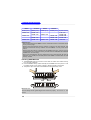
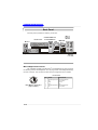
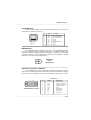
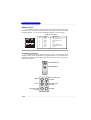
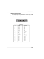
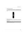
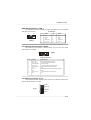
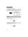
1
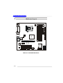
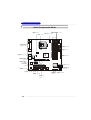
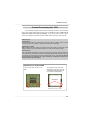
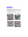
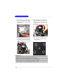
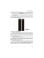
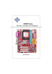
Getting Started
Chapter 1. Getting Started
Getting Started
T hank you f or c hoosing the MS-7187 v1.X Mic ro AT X
mainboard. The MS-7187 v1.X mainboard is based on Intel® 945P
and Intel® ICH7R chipset for optimal system efficiency. Designed to
fit the advanced Intel® Pentium Prescott LGA775 processor, the
MS-7187 v1.X mainboard delivers a high performance and professional desktop platform solution.
1-1
MS-7187 M-ATX M ainboard
Mainboard Specifications
CPU
† Supports Intel® Pentium 4 Prescott LGA775 processors in LGA775 package.
† Supports up to Pentium 4 3XX, 5XX and 6XX sequence processor or higher
speed.
† Supports Intel Hyper-Threading Technology.
Chipset
† Intel® 945P chipset
- Supports FSB 800/ 1066 MHz.
- Supports DDRII 533/667 memory interface.
- Supports PCI Express x 16 graphics interface.
† Intel® ICH7R chipset
- Hi-Speed USB (USB2.0) controller, 480Mb/sec, up to 8 ports.
- 4 Serial ATAII ports with transfer rate up to 3 Gb/s.
- 1 channel Ultra ATA 100 bus Master IDE controller.
- PCI Master v2.3, I/O APIC.
- ACPI 2.0 Compliant.
- SATAII RAID 0, RAID 1 and Matrix RAID.
- Integrated AHCI controller.
M ain M emory
† Supports four DDR2 SDRAM memory modules.
† Supports up to 4GB memory size.
† Supports Dual channel DDR2.
Slots
† One PCI Express x16 slot (supports PCI Express Bus specification v1.0a compliant).
† One PCI Express x1 slot
† Two 32-bit v2.3 Master PCI bus slots (support 3.3v/5v PCI bus interface).
- The first PCI slot (PCI2, in green color) supports 3 master devices.
On-Board IDE
† One Ultra DMA 66/100 IDE controllers integrated in ICH7R.
- Supports PIO, Bus Master operation modes.
- Can connect up to Two Ultra ATA drives.
† SATA2 controller integrated in ICH7R.
- Up to 3.0 Gb/s transfer rate.
- Can connect up to four SATA2 devices.
On-Board Peripherals
† On-Board Peripherals include:
- 1 floppy port supports 1 FDD with 360K, 720K, 1.2M, 1.44M and 2.88Mbytes
- 1 serial port
- 1 parallel port supports SPP/EPP/ECP mode
1-2
Getting Started
- 8 USB 2.0 / 1.1 ports (Rear*4 / Front*4)
- 1 RJ45 connector
- 1 Rear 1394 port (6 Pins) / 1 Front 1394 port
- 1 Coaxial SPDIF-Out / SPDIF-In
- 1 MIC-In
- 4 Line-Out
- 1 Line-In
LAN
† Intel® 82562GZ LAN Controller
- 10/100 IEEE 802.3/802.3u 10Base-T & 100Base-T compliant.
IEEE 1394
† VIA® VT6307 PCI 1394a Integrated Host Controller
Audio
† Azalia link controller integrated in Intel® ICH7R chipset.
† 8-channel audio codec CMedia CMI9880L.
BIOS
† The mainboard BIOS provides “Plug & Play” BIOS which detects the peripheral
devices and expansion cards of the board automatically.
† The mainboard provides a Desktop Management Interface (DMI) function which
records your mainboard specifications.
M ounting and Dimension
† M-ATX Form Factor: 24.5 cm (L) x 24.5 cm (W )
† 6 mounting holes
1-3
MS-7187 M-ATX M ainboard
D IMM4
D IMM3
Winbond
W 83627T HF
FDD1
CP U_F1
Top : mouse
Bo ttom:
keyb oard
D IMM2
D IMM1
Mainboard Layout
Top :
Parallel Port
Bottom:
COM Port
Top :
SPD IF_out
Bottom:
SPD IF_In
ATX 1
JPW1
Top: LAN Jack
Bottom: USB ports
Int el
945P
LAN
Chip
SYS_F1
ID E1
Top :1394 port
B:USB ports
PCIE_X16
PCI_E3
BATT
+
VT6307
PCI2
I ntel
IC H7R
JF_P1
SATA4 SATA2
PCI3
BIOS
Cod ec
SATA3
SATA1
J A UD1
J L_IN 1
J VI D1
J 1394_ 1
J US B1
MS-7187 v1.X M-ATX Mainboard
1-4
J US B2
JB AT1
Hardware Setup
Chapter 2. Hardware Setup
Hardware Setup
This chapter tells you how to install the CPU, memory modules, and
expansion cards, as well as how to setup the jumpers on the mainboard.
Also, it provides the instructions on connecting the peripheral devices,
such as the mouse, keyboard, etc.
W hile doing the installation, be careful in holding the components and
follow the installation procedures.
2-1
M S-7187 M -ATX M ainboard
Quick Components Guide
DDR2 DIMMs, p.2-7
JPW1, p.2-9
CPU, p.2-3
CPU_F1, p.2-14
Back Panel
I/O, p.2-10
FDD1, p.2-14
ATX1, p.2-9
SYS_F1, p.2-14
IDE1, p.2-15
PCIEx16 slot,
p.2-20
PCIEx1 slot,
p.2-20
PCI slots,
JF_P1, p.2-17
p.2-20
SATA1~4,
p.2-16
JAUD1, p.2-17
JL_IN1, p.2-18
JVID1, p.2-18
J1394_1,
p.2-17
2-2
JUSB1/2,
p.2-18
JBAT1, p.2-19
Hardware Setup
Central Processing Unit: CPU
The mainboard supports Intel® Pentium 4 Prescott processor. The mainboard
uses a CPU socket called LGA775. W hen you are installing the CPU, make sure to
install the cooler to prevent overheating. If you do not have the CPU cooler,
contact your dealer to purchase and install them before turning on the computer.
Reminds You...
Overheating
Overheating will seriously damage the CPU and system, always make sure the
cooling fan can work properly to protect the CPU from overheating.
Replacing the CPU
While replacing the CPU, always turn off the ATX power supply or unplug the power
supply’s power cord from grounded outlet first to ensure the safety of CPU.
Overclocking
This motherboard is designed to support overclocking. However, please make sure
your components are able to tolerate such abnormal setting, while doing overclocking.
Any attempt to operate beyond product specifications is not recommended. We do
not guarantee the damages or risks caused by inadequate operation or
beyond product specifications.
Introduction to LGA 775 CPU
The pin-pad side of LGA 775
CPU.
Alignment Key
Yellow triangle is the Pin 1 indicator
The surface of LGA 775 CPU.
Remember to apply some silicone heat transfer compound on
it for better heat dispersion.
Alignment Key
Yellow triangle is the Pin 1 indicator
2-3
M S-7187 M -ATX M ainboard
CPU & Cooler Installation
W hen you are installing the CPU, make sure the CPU has a cooler attached on the top to prevent overheating. If you do not have the cooler, contact
your dealer to purchase and install them before turning on the computer. Meanwhile,
do not forget to apply some silicon heat transfer compound on CPU before installing
the heat sink/cooler fan for better heat dispersion.
Follow the steps below to install the CPU & cooler correctly. W rong installation
will cause the damage of your CPU & mainboard.
1. The CPU has a plastic cap on it to
protect the contact from damage.
Before you install the CPU, always
cover it to protect the socket pin.
2. Remove the cap from lever hinge
side (as the arrow shows).
3. The pins of socket reveal.
4. Open the load lever.
2-4
Hardware Setup
5. Lift the load lever up and open the
load plate.
6. After confirming the CPU direction
for correct mating, put down the
CPU in the socket housing frame.
Be sure to grasp on the edge of
the CPU base. Note that the alignment keys are matched.
alignment
key
7. Visually ins pect if the CPU is
seated well into the socket. If not,
take out the CPU with pure vertical
motion and reinstall.
8. Cover the load plate onto the
package.
2-5
M S-7187 M -ATX M ainboard
9. Press down the load lever lightly
onto the load plate, and then secure the lever with the hook under
retention tab.
10. Align the holes on the mainboard
with the heatsink. Push down the
c ooler u nti l i ts f ou r c lip s g et
wedged int o t he holes of t he
mainboard.
11. Press the four hooks down to fasten the cooler. Then rotate the locking switch (refer to the correct direction marked on it) to lock the
hooks.
12. Turn over the mainboard to confirm that the clip-ends are correctly inserted.
locking
switch
Reminds You...
1. Confirm if your CPU cooler is firmly installed before turning on your system.
2. Do not touch the CPU socket pins to avoid damaging.
3. Whenever CPU is not installed, always protect your CPU socket pin with the
plastic cap covered (shown in Figure 1) to avoid damaging.
4. Please note that the mating/unmating durability of the CPU is 20 cycles. Therefore we suggest you do not plug/unplug the CPU too often.
2-6
Hardware Setup
Memory
The mainboard provides 4 slots for 240-pin DDR2 DIMM, which supports the
memory size up to 4GB.
Since DDR2 modules are not interchangeable with DDR1 and the DDR2 standard is not backward compatible, you should always install DDR2 memory module in
the DDR2 slot (DIMM1~DIMM4). Otherwise, you are not able to boot up your system
and your mainboard might be damaged.
DDR2 DIMM Slots
(DIMM 1~4)
Introduction to DDR2 SDRAM
DDR2 is a new technology of memory module, and its speed is the top limit of
current DDR1 technology. DDR2 uses a 1.8V supply for core and I/O voltage, compared to 2.5V for DDR1, and requires 28% less power than DDR1 chips. DDR2 truly
is the future of memory, but will require some changes as the technology is not
backwardly compatible and only motherboards specifically designed for DDR2 memory
will be able to support these chips.
DDR2 incorporates new features at the chip level that give it better signal
integrity, thereby enabling higher clock speeds.
DDR2 modules have 240 pins, versus 184 pins on a DDR1 module, and the
length of DDR2 module is 5.25”. DDR2 modules have smaller and tighter spaced pins.
The height of DDR2 modules varies, but they will typically be less than 1.3” in height.
Memory Module Population Rules
Install at least one DIMM module on the slots. Each DIMM slot supports up to a
maximum size of 1GB. Users can install either single- or double-sided modules to
meet their own needs. Please note that each DIM M can work respectively for
single-channel DDR, while both channels (in different color) populated
with same amount of memory size will work as dual-channel DDR.
2-7
M S-7187 M -ATX M ainboard
GREEN
ORANGE
DIMM1 (Ch A)
DIMM2 (Ch B)
256MB~1GB
256MB~1GB
256MB~1GB
GREEN
ORANGE
DIMM3 (Ch A)
DIMM4 (Ch B)
512B~2GB
256MB~1GB
256MB~1GB
256MB~1GB
256MB~1GB
256MB~1GB
System Density
256MB~1GB
512MB~2GB
256MB~4GB
512MB~2GB
256MB~1GB
512MB~2GB
256MB~1GB
1GB~4GB
Reminds You...
- Dual-channel DDR works ONLY in the 5 combinations listed in the table shown
in the previous page.
- Please select the identical memory modules to install on the dual channel, and
DO NOT install three memory modules on three DIMMs, or it may cause some
failure.
- Always insert the memory modules into the GREEN slots first, and it is strongly
recommended not to insert the memory modules into the ORANGE slots while the
GREEN slots are left empty.
- Due to the South Bridge resource deployment, the system density will only be
detected up to 3+GB (not full 4GB) when each DIMM is installed with an 1GB
memory module.
Installing DDR2 Modules
1. The DDR DIMM has only one notch on the center of module. The module will only
fit in the right orientation.
2. Insert the DIMM memory module vertically into the DIMM slot. Then push it in until
the golden finger on the memory module is deeply inserted in the socket.
3. The plastic clip at each side of the DIMM slot will automatically close.
Volt
Notch
Reminds You...
You can barely see the golden finger if the module is properly i n s e r t e d i n t h e
socket.
2-8
Hardware Setup
Power Supply
The mainboard supports ATX power supply for the power system. Before
inserting the power supply connector, always make sure that all components are
installed properly to ensure that no damage will be caused.
ATX 24-Pin Power Connector: ATX1
This connector allows you to connect an ATX 24-pin power supply. To
connect the ATX 24-pin power supply, make sure the plug of the power supply is
inserted in the proper orientation and the pins are aligned. Then push down the
power supply firmly into the connector.
12
Pin Definition
24
PIN
SIGNAL
PIN
SIGNAL
1
+3.3V
13
+3.3V
2
3
+3.3V
GND
14
15
-12V
GND
4
5
+5V
GND
16
17
PS-ON#
GND
6
7
+5V
GND
18
19
GND
GND
8
9
PWR OK
5VSB
20
21
Res
+5V
10
+12V
22
+5V
11
+12V
12
NC
23
24
+5V
GND
ATX1
1
13
ATX 12V Power Connector: JPW1
This 12V power connector is used to provide power to the CPU.
JPW1 Pin Definition
1
3
JPW1
2
4
PIN
SIGNAL
1
GND
2
3
GND
12V
4
12V
Reminds You...
1. These two connectors connect to the ATX power supply and have to work together
to ensure stable operation of the mainboard.
2. Power supply of 400 watts (and above) is highly recommended for system stability.
3. ATX 12V power connection should be greater than 18A.
2-9
M S-7187 M -ATX M ainboard
Back Panel
The back panel provides the following connectors:
Parallel Port
MIC-in
Line-In
BS-Out
Coaxial-SPDIF Out
Coaxial-SPDIF In
M o us e
LAN
Keyboard COM Port
IEEE1394
Port
USB Ports
C/S Out
SS-Out
Line-Out
Mouse/Keyboard Connector
The mainboard provides a standard PS/2® mouse/keyboard mini DIN connector
for attaching a PS/2® mouse/keyboard. You can plug a PS/2® mouse/keyboard directly
into this connector. The connector location and pin assignments are as follows:
Pin Definition
6
5
3
4
2
1
PS/2 Mouse / Keyboard
(6-pin Female)
2-10
PIN
SIGNAL
DESCRIPTION
1
Mouse/Keyboard Data
Mouse/Keyboard data
2
3
NC
GND
No connection
Ground
4
5
VCC
Mouse/KeyboardClock
+5V
Mouse/Keyboard clock
6
NC
No connection
Hardware Setup
RJ-45 LAN Jack
The mainboard provides a RJ-45 connector that allows your computer to be
connected to a network environment.
Pin
LAN Jack
(RJ-45)
Signal
Description
1
2
TDP
TDN
Transmit differential pair
Transmit differential pair
3
4
RDP
NC
Receive differential pair
Not used
5
6
NC
RDN
Not used
Receive differential pair
7
8
NC
NC
Not used
Not used
IEEE1394 Port
The mainboard provides a rear IEEE 1394 port. The standard IEEE1394 port
connects to IEEE1394 devices without external power. The IEEE1394 high-speed
serial bus complements USB by providing enhanced PC connectivity for a wide range
of devices, including consumer electronics audio/video (A/V) appliances, storage
peripherals, other PCs, and portable devices.
IEEE 1394
Port
(Standard)
Serial Port Connector: COM Port
The mainboard offers one 9-pin male DIN connectors as serial port COM port.
This port is a 16550A high speed communication port that sends/receives 16 bytes
FIFOs. You can attach a serial mouse or other serial devices directly to this connector.
Pin Definition
1 2
6
3
7
4
8
5
9
9-Pin Male DIN Connector
PIN
SIGNAL
DESCRIPTION
1
2
DCD
SIN
Data Carry Detect
Serial In or Receive Data
3
4
SOUT
DTR
Serial Out or Transmit Data
Data Terminal Ready)
5
6
GND
DSR
Ground
Data Set Ready
7
8
RTS
CTS
Request To Send
Clear To Send
9
RI
Ring Indicate
2-11
M S-7187 M -ATX M ainboard
USB Connectors
The mainboard provides a UHCI (Universal Host Controller Interface) Universal
Serial Bus root for attaching USB devices such as keyboard, mouse or other USBcompatible devices. You can plug the USB device directly into the connector.
USB Port Description
1
5
2
6
3
7
4
8
PIN
SIGNAL
DESCRIPTION
1
2
VCC
-Data 0
+5V
Negative Data Channel 0
3
4
+Data0
GND
Positive Data Channel 0
Ground
5
6
VCC
-Data 1
+5V
Negative Data Channel 1
7
8
+Data 1
GND
Positive Data Channel 1
Ground
USB Ports
Audio Port Connectors
This mainboard supports 8-channel audio operation. To have correct audio
operation, please connect the speakers to the proper connectors as illustrated below.
The SPDIF connectors provided on the back panel also can be used to connect your
digital audio equipment.
Coaxial-SPDIF Out
Coaxial-SPDIF In
MIC-in
Center Surround
Line-Out
Line-In
Side Surround
Line-Out
Back Surround
Line-Out
2-12
Line-Out
Hardware Setup
Parallel Port Connector: LPT1
The mainboard provides a 25-pin female centronic connector as LPT. A parallel
port is a standard printer port that supports Enhanced Parallel Port (EPP) and Extended Capabilities Parallel Port (ECP) mode.
13
1
14
25
Pin Definition
PIN
SIGNAL
DESCRIPTION
1
2
STROBE
DATA0
Strobe
Data0
3
4
DATA1
DATA2
Data1
Data2
5
6
DATA3
DATA4
Data3
Data4
7
8
DATA5
DATA6
Data5
Data6
9
10
DATA7
ACK#
Data7
Acknowledge
11
12
BUSY
PE
Busy
PaperEnd
13
14
SELECT
AUTO FEED#
Select
AutomaticFeed
15
16
ERR#
INIT#
Error
Initialize Printer
17
18
SLIN#
GND
Select In
Ground
19
20
GND
GND
Ground
Ground
21
22
GND
GND
Ground
Ground
23
24
GND
GND
Ground
Ground
25
GND
Ground
2-13
M S-7187 M -ATX M ainboard
Connectors
The mainboard provides connectors to connect to FDD, IDE HDD, case, LAN,
USB Ports, IR module and CPU/System/Power Supply FAN.
Floppy Disk Drive Connector: FDD1
The mainboard provides a standard floppy disk drive connector that supports
360K, 720K, 1.2M, 1.44M and 2.88M floppy disk types.
FDD1
Fan Power Connectors: CPU_F1 & SYS_F1
The CPU_F1 (processor fan) and SYS_F1 (system fan) support system cooling fan with +12V. It supports four/three-pin head connector. W hen connecting the
wire to the connectors, always take note that the red wire is the positive and should
be connected to the +12V, the black wire is Ground and should be connected to GND.
If the mainboard has a System Hardware Monitor chipset on-board, you must use a
specially designed fan with speed sensor to take advantage of the CPU fan control.
GND
+12V
SENSOR
control
CPUFAN1
Sensor
+12V
GND
SYS_F1
Reminds You...
1. Always consult the vendors for proper CPU cooling fan.
2. CPU_F1 supports the fan control. Fan/heatsink with 3 or 4 fins are both available.
3. Please refer to the recommended CPU fans at Intel® official website.
2-14
Hardware Setup
Hard Disk Connector: IDE1
The mainboard has one 32-bit Enhanced PCI IDE and Ultra DMA 33/66/100
controller that provides PIO mode 0~4, Bus Master, and Ultra DMA33/66/100 function.
You can connect up to 2 hard disk drives, CD-ROM, 120MB Floppy (reserved for
future BIOS) and other devices. The connector supports the provided IDE hard disk
cable.
IDE1
IDE1 (Primary IDE Connector)
The first hard drive should always be connected to IDE1. IDE1 can connect a Master
and a Slave drive. You must configure second hard drive to Slave mode by setting the
jumper accordingly.
Reminds You...
If you install two hard disks on cable, you must configure the second drive to Slave
mode by setting its jumper. Refer to the hard disk documentation supplied by hard
disk vendors for jumper setting instructions.
2-15
M S-7187 M -ATX M ainboard
Serial ATA Connectors controlled by Intel ICH7R: SATA1~SATA4
The SouthBridge of this mainboard is Intel ICH7R which supports four serial
ATA connectors SATA1~SATA4.
SATA1~SATA4 are dual high-speed Serial ATA interface ports. Each supports
1st generation serial ATA data rates of 3Gb. All connectors are fully compliant with
Serial ATA 1.0 specifications. Each Serial ATA connector can connect to 1 hard disk
device.
SATA4 SATA2
SATA1~ SATA4 Pin Definition
1
7
1
7
SATA3
PIN
SIGNAL
PIN
SIGNAL
1
GND
2
TXP
3
5
TXN
RXN
4
6
GND
RXP
7
GND
SATA1
Serial ATA cable
Take out the dust cover and
connect to the hard disk
devices
Connect to serial ATA ports
Reminds You...
Please do not fold the serial ATA cable in a 90-degree angle, since this might cause
the loss of data during the transmission.
2-16
Hardware Setup
IEEE 1394 Connectors: J1394_1
The mainboard provides one IEEE1 pin header that allows you to connect IEEE
1394 port via front panel.
Pin Definition
10
2
9
1
J1394_1
PIN
SIGNAL
PIN
SIGNAL
1
TPA+
2
TPA-
3
Ground
4
Ground
5
TPB+
6
TPB-
7
Cable power
8
Cable power
9
Key (no pin)
10
Ground
Front Panel Audio Connector: JAUD1
The JAUD1 front panel audio connector allows you to connect front panel
audio devices if available.
10
9
2
1
JAUD1
JAUD1 Pin Definition
PIN
SIGNAL
DESCRIPTION
1
AUD_MIC
Front panel microphone input signal
2
3
AUD_GND
AUD_MIC_BIAS
Ground used by analog audio circuits
Microphone power
4
5
AUD_VCC
AUD_FPOUT_R
Filtered +5V used by analog audio circuits
Right channel audio signal to front panel
6
7
NC
HP_ON
NC
Reserved for future use to control headphone amplifier
8
9
KEY
AUD_FPOUT_L
No pin
Left channel audio signal to front panel
10
NC
NC
Front Panel Connector: JF_P1
The mainboard provides one front panel connector for electrical connection to
the front panel switches and LEDs.
1
PS-ON
PWR_LED
JF_P1
HDD_LED
8
Reset
2-17
M S-7187 M -ATX M ainboard
Front USB Connector: JUSB1/JUSB2
The mainboard provides two USB 2.0 pin headers that are compliant with Intel®
I/O Connectivity Design Guide. USB 2.0 technology increases data transfer rate up to
a maximum throughput of 480Mbps, which is 40 times faster than USB 1.1, and is
ideal for connecting high-speed USB interface peripherals such as USB HDD, digital
cameras, M P3 players, printers, modems and the like.
Pin Definition
10
9
2
1
JUSB1/JUSB2
(USB 2.0)
PIN
SIGNAL
PIN
SIGNAL
1
VCC
2
VCC
3
USB0-
4
USB1-
5
USB0+
6
USB1+
7
GND
8
GND
9
Key
10
USBOC
Reminds You...
Note that the pins of VCC and GND must be connected correctly, or itmay cause
some damage.
Video-In Connector: JVID1
The connector is for TV-Turner card audio connector.
L GND R
JVID1
Front Audio Line-In Connector: JL_IN1
The JL_IN1 Front Audio Line-In connector allows you to connect front panel
audio devices if available.
L GND R
JL_IN1
2-18
Hardware Setup
Jumpers
The motherboard provides the following jumpers for you to set the computer’s
function. This section will explain how to change your motherboard’s function through
the use of jumpers.
Clear CMOS Jumper: JBAT1
There is a CMOS RAM on board that has a power supply from external battery
to keep the data of system configuration. W ith the CMOS RAM, the system can
automatically boot OS every time it is turned on. That battery has long life time for at
least 5 years. If you want to clear the system configuration, use the JBAT1 (Clear
CMOS Jumper) to clear data. Follow the instructions below to clear the data:
1
3
JBAT1
Keep Data
1
3
Clear Data
1
3
Reminds You...
You can clear CMOS by shorting 2-3 pin while the system is off. Then return to 1-2
pin position. Avoid clearing the CMOS while the system is on; it will damage the
mainboard.
2-19
M S-7187 M -ATX M ainboard
Slots
The motherboard provides one PCI Express x16 slot and three 32-bit PCI bus
slots.
PCI Express Slots
The PCI Express slots, as a high-bandwidth, low pin count, serial, interconnect technology, support Intel highest performance desktop platforms utilizing the
Intel Pentium 4 processor with HT Technology.
PCI Express architecture provides a high performance I/O infrastructure for
Desktop Platforms with transfer rates starting at 2.5 Giga transfers per second over
a PCI Express x1 lane for Gigabit Ethernet, TV Tuners, 1394 controllers, and general
purpose I/O. Also, desktop platforms with PCI Express Architecture will be designed
to deliver highest performance in video, graphics, multimedia and other sophisticated
applications. Moreover, PCI Express architecture provides a high performance graphics
infrastructure for Desktop Platforms doubling the capability of existing AGP 8x designs with transfer rates of 4.0 GB/s over a PCI Express x16 lane for graphics
controllers.
You can insert the expansion cards to meet your needs. W hen adding or
removing expansion cards, make sure that you unplug the power supply first.
PCI Express x16 slot
PCI Express x1 slot
PCI (Peripheral Component Interconnect) Slots
The PCI slots allow you to insert the expansion cards to meet your needs.
W hen adding or removing expansion cards, make sure that you unplug the power
supply first. Meanwhile, read the documentation for the expansion card to make any
necessary hardware or software settings for the expansion card, such as jumpers,
switches or BIOS configuration. The first PCI slot (in GREEN color) supports 2
master devices.
PCI Slots
PCI Interrupt Request Routing
The IRQ, acronym of interrupt request line and pronounced I-R-Q, are hardware lines over which devices can send interrupt signals to the microprocessor. The
PCI IRQ pins are typically connected to the PCI bus INT A# ~ INT D# pins as follows:
Order 1
Order 2
Order 3
Order 4
PCI Slot 1
INT A#
INT B#
INT C#
INT D#
PCI Slot 2
INT B#
INT C#
INT D#
INT A#
2-20