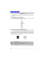
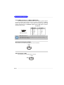
1
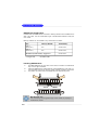
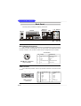
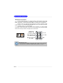
MS-7174 (v1.X M-ATX Mainboard)
i
Manual Rev: 1.0
Release Date: April. 2005
FCC-B Radio Frequency Interference Statement
This equipment has been tested and found to comply with the limits for a class B
digital device, pursuant to part 15 of the FCC rules. These limits are designed to
provide reasonable protection against harmful interference when the equipment is
operated in a commercial environment. This equipment generates, uses and can
radiate radio frequency energy and, if not installed and used in accordance with the
instruction manual, may cause harmful interference to radio communications. Operation
of this equipment in a residential area is likely to cause harmful interference, in which
case the user will be required to correct the interference at his own expense.
Notice 1
The changes or modifications not expressly approved by the party responsible for
compliance could void the user’s authority to operate the equipment.
Notice 2
Shielded interface cables and A.C. power cord, if any, must be used in order to
comply with the emission limits.
VOIR LA NOTICE D’INSTALLATION AVANT DE RACCORDER AU RESEAU.
Micro-Star International
MS-7174
This device complies with Part 15 of the FCC Rules. Operation is subject to the
following two conditions:
(1) this device may not cause harmful interference, and
(2) this device must accept any interference received, including interference that
may cause undesired operation
ii
Copyright Notice
T he material in this document is the intellec tual property of M ICRO-STAR
INTERNATIONAL. W e take every care in the preparation of this document, but no
guarantee is given as to the correctness of its contents. Our products are under
continual improvement and we reserve the right to make changes without notice.
Trademarks
All trademarks are the properties of their respective owners.
AMD, Athlon™, Athlon™ XP, Thoroughbred™, and Duron™ are registered trademarks of AMD Corporation.
Intel® and Pentium® are registered trademarks of Intel Corporation.
PS/2 and OS ® /2 are registered trademarks of International Business Machines
Corporation.
Microsoft is a registered trademark of Microsoft Corporation. W indows ® 98/2000/NT/
XP are registered trademarks of Microsoft Corporation.
NVIDIA, the NVIDIA logo, DualNet, and nForce are registered trademarks or trademarks of NVIDIA Corporation in the United States and/or other countries.
Netware® is a registered trademark of Novell, Inc.
Award® is a registered trademark of Phoenix Technologies Ltd.
AMI® is a registered trademark of American Megatrends Inc.
Kensington and MicroSaver are registered trademarks of the Kensington Technology
Group.
PCMCIA and CardBus are registered trademarks of the Personal Computer Memory
Card International Association.
Revision History
Revision
V1.0
Revision History
First release for PCB 1.X
with Intel 915GE & ICH6
iii
Date
April 2005
Technical Support
If a problem arises with your system and no solution can be obtained from the user’s
manual, please contact your place of purchase or local distributor. Alternatively,
please try the following help resources for further guidance.
† Visit the MSI homepage & FAQ site for technical guide, BIOS updates, driver
updates, and other information: http://www.msi.com.tw & http://www.msi.
com.tw/program/service/faq/faq/esc_faq_list.php
† Contact our technical staff at: [email protected]
Safety Instructions
1.
2.
3.
4.
5.
Always read the safety instructions carefully.
Keep this User’s Manual for future reference.
Keep this equipment away from humidity.
Lay this equipment on a reliable flat surface before setting it up.
The openings on the enclosure are for air convection hence protects the equipment from overheating. Do not cover the openings.
6. Make sure the voltage of the power source and adjust properly 110/220V before connecting the equipment to the power inlet.
7. Place the power cord such a way that people can not step on it. Do not place
anything over the power cord.
8. Always Unplug the Power Cord before inserting any add-on card or module.
9. All cautions and warnings on the equipment should be noted.
10. Never pour any liquid into the opening that could damage or cause electrical
shock.
11. If any of the following situations arises, get the equipment checked by a service
personnel:
† The power cord or plug is damaged.
† Liquid has penetrated into the equipment.
† The equipment has been exposed to moisture.
† The equipment has not work well or you can not get it work according to
User’s Manual.
† The equipment has dropped and damaged.
† The equipment has obvious sign of breakage.
12. Do not leave this equipment in an environment unconditioned, storage
temperature above 60 0 C (140 0F), it may damage the equipment.
CAUT ION: Danger of explosion if battery is incorrec tly replac ed.
Replace only with the same or equivalent type recommended by the
manufacturer.
iv
CONTENTS
FCC-B Radio Frequency Interference Statement ......................................................... ii
Copyright Notice .............................................................................................................. iii
Revision History .............................................................................................................. iii
Technical Support .......................................................................................................... iv
Safety Instructions ......................................................................................................... iv
Chapter 1. Getting Started .................................................................................... 1-1
Mainboard Specifications ................................................................................... 1-2
Mainboard Layout ................................................................................................ 1-4
Chapter 2. Hardware Setup .................................................................................. 2-1
Quick Components Guide ................................................................................... 2-2
Central Processing Unit: CPU ............................................................................. 2-3
Introduction to LGA 775 CPU ...................................................................... 2-3
CPU & Cooler Installation ............................................................................. 2-4
Memory ................................................................................................................. 2-7
Introduction to DDR SDRAM ....................................................................... 2-6
DDR Module Combination ............................................................................ 2-8
Installing DDR Modules ................................................................................ 2-8
Power Supply ...................................................................................................... 2-9
ATX 24-Pin Power Connector: ATX1 ......................................................... 2-9
ATX 12V Power Connector: ATX_IN .......................................................... 2-9
Back Panel ......................................................................................................... 2-10
Mouse/Keyboard Connector .................................................................... 2-10
VGA Connector .......................................................................................... 2-10
USB Connectors ......................................................................................... 2-11
LAN (RJ-45) Jack ....................................................................................... 2-11
Audio Port Connectors .............................................................................. 2-12
Parallel Port Connector: LPT1 ................................................................... 2-13
Connectors ........................................................................................................ 2-14
Floppy Disk Drive Connector: FDD1 ......................................................... 2-14
Fan Power Connectors: CPU_FAN1/ SYS_FAN1 ................................... 2-14
Hard Disk Connector: IDE1 ....................................................................... 2-15
FWH/LPC Debugging Pin Header: JLPC1 ................................................. 2-15
Serial ATA Connectors controlled by Intel ICH6 SATA1~SATA2 ............ 2-16
Front Panel Connectors: JFP1 .................................................................. 2-17
Front Panel Audio Connector: JAUD1 ....................................................... 2-17
Front USB Connectors: FUSB1/2 (USB5/6/7/8) ....................................... 2-18
v
Aux Line_In Connector: JAUX1 ................................................................ 2-18
CD-In Connector: JCD1 ............................................................................. 2-18
IEEE 1394 Connector: J1394_1 (Optional) .............................................. 2-19
Jumpers .............................................................................................................. 2-20
Clear CMOS Jumper: JBAT1 ..................................................................... 2-20
Clear BIOS Password Jumper: JPWD1 ................................................... 2-20
Slots .................................................................................................................... 2-21
PCI Express Slots ...................................................................................... 2-21
PCI (Peripheral Component Interconnect) Slots ...................................... 2-21
PCI Interrupt Request Routing ................................................................... 2-21
vi
Getting Started
Chap t er 1 . Ge tting
Started
Getting Started
T hank you f or c hoosing the MS-7174 v1.x Micro AT X
mainboard. The mainboard is based on Intel® 910GE and Intel® ICH6
chipset for optimal system efficiency. Designed to fit the advanced
Intel ® Pentium 4 Prescott LG A775 proc es sor, the MS-7142
mainboard delivers a high performance and professional desktop
platform solution.
1-1
M S-7174 M -ATX M ainboard
Mainboard Specifications
CPU
† Supports Intel® Pentium 4/ Celeron D Prescott LGA775 processors in LGA775
package.
† Supports 2005 Mainstream FMB CPU VR Design.
† Supports 4 pin CPU Fan Pin-Header with Fan Speed Control.
† Supports up to Pentium 4 3XX, 5XX.
(For the latest information about CPU, please visit http://www.msi.com.tw/program/
products/mainboard/mbd/pro_mbd_cpu_support.php)
Chipset
† Intel® 910GE chipset
- Supports FSB 533MHz.
- Supports PCI Express x16 interface.
- Supports DDR2 400/533 memory interface.
- Integrated graphics controller.
† Intel® ICH6 chipset
- Hi-Speed USB (USB2.0) controller, 480Mb/sec, up to 8 ports.
- Supports up to 4 Serial ATA ports .
- 1 channel Ultra ATA 100 bus Master IDE controller.
- PCI Master v2.3, I/O APIC.
- ACPI 2.0 Compliant.
M ain M emory
† Supports two unbuffered DIMM of 1.8 Volt DDR2 SDRAM
† Supports up to 2GB memory size.
† Supports Dual channel DDR2 memory architecture.
† Supports DDR2 400/533 memory interface.
(For the updated supporting memory modules, please visit http://www.msi.com.tw/
program/products/mainboard/mbd/pro_mbd_trp_list.php.)
Slots
† One PCI Express x16 slot (supports PCI Express Bus specification v1.0a compliant)
† Three 32-bit v2.3 Master PCI bus slots (support 3.3v/5v PCI bus interface).
On-Board IDE
† One Ultra DMA 33/66/100 IDE controllers integrated in ICH6.
- Supports PIO, Bus Master operation modes.
- Can connect up to Two Ultra ATA drives.
† Serial ATA controller integrated in ICH6.
- Up to 150MB/sec transfer speed.
- Can connect up to four Serial ATA devices.
1-2
Getting Started
On-Board Peripherals
† On-Board Peripherals include:
- 1 floppy port supports 1 FDD with 360K, 720K, 1.2M, 1.44M and 2.88Mbytes
- 2 SPDIF ports
- 1 VGA port
- 1 parallel port supports SPP/EPP/ECP mode
- 1 Line-In / Line-Out / MIC-In / Rear Speaker Out / Center-Subwoofer Speaker Out/
Side Surround Out
- 8 USB ports (Rear * 6/ Front * 2)
- 1 RJ-45 LAN jack
LAN
† Intel 82562GT 10/100 Ethernet PHY
- Supports 10/ 100 Mb/s .
- Compliane with PCI 2.2.
- Supports ACPI Power Management.
1394 (optional)
† Supports two IEEE1394 onboard pinheader. Transfer rate is up to 400 Mbps.
† Controlled by VIA VT6307 chipset.
Audio
† High Definition link controller integrated in Intel® ICH6R/ICH6 chip.
† 8-channel audio codec Realtek ALC880.
- Compliant with Azalia 1.0 Spec.
BIOS
† The mainboard BIOS provides “Plug & Play” BIOS which detects the peripheral
devices and expansion cards of the board automatically.
† The mainboard provides a Desktop Management Interface (DMI) function which
records your mainboard specifications.
M ounting and Dimension
† M-ATX Form Factor: 9.6 inch (W) x 9.6 inch (L)
† 8 mounting holes
1-3
M S-7174 M -ATX M ainboard
DIMM1
Top : mouse
Bot tom:
k ey boar d
DIMM2
Mainboard Layout
CPU_FAN
ATX_IN
FDD1
ATX1
To p :
Parallel Por t
Top :1 394 port
B:USB ports
Intel
BIOS
Top: LA N Jack
Bot tom : U SB ports
SYS_FAN1
IDE1
JLPC1
PCI_Express
VIA
VT6307
BATT
+
PCI1
Intel
PCI2
ALC880
JBAT1
SATA1
PCI3
JAUD1
JC D1 JAUX 1
JFP1
J1394_1
F_US B2 U SB5,6 F_U SB1 U SB7, 8
JPWD1
MS-7174 v1.x M-ATX Mainboard
1-4
SATA2
Hardware Setup
Chapter 2. Hardware
Setup
Hardware Setup
This chapter tells you how to install the CPU, memory modules,
and expansion cards, as well as how to setup the jumpers on the
mainboard. Also, it provides the instructions on connecting the peripheral devices, such as the mouse, keyboard, etc.
W hile doing the installation, be careful in holding the components and follow the installation procedures.
2-1
M S-7174 M -ATX M ainboard
Quick Components Guide
CPU_FAN,
CPU,
p.2-3
JPW1,
p.2-9
p.2-14
DDR2 DIMMs,
DIMM1
Top : mouse
Bott om:
keyboar d
DIMM2
p.2-7
CPU_FAN
ATX1,
p.2-9
Top :
Parallel Por t
FDD1,
p.2-14
Back Panel
ATX_IN
FDD1
ATX1
I/O, p.2-10
Top :1394 port
B:USB ports
IDE1,
p.2-15
Intel
BIOS
Top: LAN Jack
Bot tom: USB ports
SYS_FAN1
JLPC1
IDE1
SYS_FAN,
p.2-14
PCI Express x 16,
PCI_Express
BATT
+
VIA
VT6307
p.2-21
JLPC1,
p.2-15
PCI1
JBAT1,
Intel
PCI2
PCI Slots 1~3,
JBAT1
ALC880
p.2-21
SATA1
PCI3
JA UD1
JFP1,
JCD1 JAU X1
JFP1
J1394_1
F_US B2 USB5,6 F_USB1 USB7, 8
JAUD1,
p.2-17
JCD1,
p.2-18
JPWD1
SATA1~SATA2,
F US B1 /2 /5 /
JAUX1,
p.2-18
J1394_1,
p.2-19
2-2
p.2-20
SATA2
6/7/8, p.2-18
p.2-16
JPWD1,
p.2-20
p.2-17
Hardware Setup
Central Processing Unit: CPU
The mainboard supports Intel® Pentium 4 Prescott processor. The mainboard
uses a CPU socket called LGA775. W hen you are installing the CPU, make sure to
install the cooler to prevent overheating. If you do not have the CPU cooler,
contact your dealer to purchase and install them before turning on the computer.
For the latest information about CPU, please visit http://www.msi.com.tw/
program/products/mainboard/mbd/pro_mbd_cpu_support.php.
MSI Reminds You...
Overheating
Overheating will seriously damage the CPU and system, always make
sure the cooling fan can work properly to protect the CPU from
overheating.
Replacing the CPU
While replacing the CPU, always unplug the power supply’s power
cord from grounded outlet first to ensure the safety of CPU.
Introduction to LGA 775 CPU
The pin-pad side of LGA 775
CPU.
Alignment Key
Yellow triangle is the Pin 1 indicator
The surface of LGA 775 CPU.
Remember to apply some silicone heat transfer compound on
it for better heat dispersion.
Alignment Key
Yellow triangle is the Pin 1 indicator
2-3
M S-7174 M -ATX M ainboard
CPU & Cooler Installation
W hen you are installing the CPU, make sure the CPU has a cooler attached on the top to prevent overheating. If you do not have the cooler, contact
your dealer to purchase and install them before turning on the computer. Meanwhile,
do not forget to apply some silicon heat transfer compound on CPU before installing
the heat sink/cooler fan for better heat dispersion.
Follow the steps below to install the CPU & cooler correctly. W rong installation
will cause the damage of your CPU & mainboard.
1. The CPU has a land side cover on the
bottom to protect the CPU contact from
damage. Rotate it to make the pin 1
indicator (yellow triangle) in the rightbottom corner.
2. Take out the accompanying CPU Clip
and rotate it for the same direction
as the CPU (Pin 1 indicator is in the
left-bottom corner).
land side cover
3. Use 2 hands to remove the land side
cover (if any). Please note not to touch
the pins.
4. Align the two pin 1 indicators (the
triangles on the CPU & the CPU Clip),
and use the CPU Clip to clip the CPU
up, pressing the clips on both sides
to the center, as the arrows shown.
MSI Reminds You...
1. Confirm if your CPU cooler is firmly installed before turning on your
system.
2. Do not touch the CPU socket pins to avoid damaging.
3. The availability of the CPU land side cover depends on your CPU
packing.
2-4
Hardware Setup
5. The CPU has a plastic cap on it to
protect the contact from damage.
Before you have installed the CPU,
always cover it to protect the socket
pin.
6. Remove the cap from lever hinge side
(as the arrow shows). The pins of
socket reveal.
7. Lift the load lever up and open the
load plate.
8. Correctly align the triangle of CPU Clip
with the CPU chamfer, and the square
on the CPU Clip to the hook of the
socket.
9. Use your thumb and the middle fingers to push the clips to release the
CPU, then press down the CPU with
your index finger to allow the whole
module to be installed onto the CPU
socket.
10. The CPU is installed well on the CPU
socket.
2-5
M S-7174 M -ATX M ainboard
11. Visually inspect if the CPU is seated
well into the socket, then remove the
CPU Clip with 2 fingers. Then cover
the load plate onto the package.
12. Press down the load lever lightly
onto the load plate, and then secure
the lever with the hook under retention tab.
13.Position the mainboard into the chassis and use the retaining screws to
secure it into the place. Then align
the holes on the mainboard and chassis with the cooler.
14.Put down the cooler and us e the
retaining screws of the cooler to secure it into the place. Make sure the
cooler is in the proper orientation, the
c ool er wi l l on l y f i t i n t he r ig h t
orientation. (Please refer the pictures
below.)
Holes on mainboard
Holes on case
The fan of the cooler.
MSI Reminds You...
1. Check the information in PC Health Status of H/W M onitor in BIOS
(Chapter 3) for the CPU temperature.
2. Whenever CPU is not installed, always protect your CPU socket pin
with the plastic cap covered (shown in Figure 1) to avoid damaging.
3. Please note that the mating/unmating durability of the CPU is 20 cycles.
Therefore we suggest you do not plug/unplug the CPU too often.
2-6
Hardware Setup
Memory
The mainboard provides two 240-pin unbuffered DDR266/DDR333/DDR400 DDR
SDRAM, and supports the memory size up to 2GB without ECC. To operate properly,
at least one DIMM module must be installed.
(For the updated supporting memory modules, please visit http://www.msi.com.tw/
program/products/mainboard/mbd/pro_mbd_trp_list.php )
DDR DIMM Slots
(DDR 1~2)
Introduction to DDR SDRAM
DDR (Double Data Rate) SDRAM is similar to conventional SDRAM, but doubles the
rate by transferring data twice per cycle. It uses 2.5 volts as opposed to 3.3 volts
used in SDR SDRAM, and requires 184-pin DIMM modules rather than 168-pin DIMM
modules used by SDR SDRAM.
2-7
M S-7174 M -ATX M ainboard
DDR Module Combination
Install at least one DIMM module on the slots. Memory modules can be installed on the
slots in any order. You can install either single- or double-sided modules to meet your
own needs.
Memory modules can be installed in any combination as follows:
Slot
DDR 1
(Bank 0 & 1)
DDR 2
(Bank 2 & 3)
Memory Module
Total Memory
S/D
64MB~1GB
S/D
64MB~1GB
Maximum System Memory Supported
S: Single Side
64MB~2GB
D: Double Side
Installing DDR Modules
1.
2.
3.
The DDR DIMM has only one notch on the center of module. The module will
only fit in the right orientation.
Insert the DIMM memory module vertically into the DIMM slot. Then push it in
until the golden finger on the memory module is deeply inserted in the socket.
The plastic clip at each side of the DIMM slot will automatically close.
Volt
Notch
MSI Reminds You...
You can barely see the golden finger if the module is properly inserted in the socket.
2-8
Hardware Setup
Power Supply
The mainboard supports ATX power supply for the power system. Before
inserting the power supply connector, always make sure that all components are
installed properly to ensure that no damage will be caused.
ATX 24-Pin Power Connector: ATX1
This connector allows you to connect an ATX 24-pin power supply. To
connect the ATX 24-pin power supply, make sure the plug of the
pin 13
power supply is inserted in the proper orientation and the pins are
aligned. Then push down the power supply firmly into the connector.
You may use the 20-pin ATX power supply as you like. If
you’d like to use the 20-pin ATX power supply, please plug your
power supply along with pin 1 & pin 13 (refer to the image at the
right hand). There is also a foolproof design on pin 11, 12, 23 & 24
to avoid wrong installation.
pin 12
Pin Definition
13
1
ATX1
24
12
PIN
SIGNAL
PIN
SIGNAL
1
2
+3.3V
+3.3V
13
14
+3.3V
-12V
3
4
GND
+5V
15
16
GND
PS-ON#
5
6
GND
+5V
17
18
GND
GND
7
8
GND
PWR OK
19
20
GND
Res
9
10
5VSB
+12V
21
22
+5V
+5V
11
12
+12V
+3.3V
23
24
+5V
GND
ATX 12V Power Connector: ATX_IN
This 12V power connector is used to provide power to the CPU.
Pin Definition
ATX_IN
2
1
PIN
SIGNAL
4
3
1
GND
2
3
GND
12V
4
12V
MSI Reminds You...
1. These two connectors connect to the ATX power supply and have to
work together to ensure stable operation of the mainboard.
2. Power supply of 350 watts (and above) is highly recommended for
system stability.
3. ATX 12V power connection should be greater than 18A.
2-9
M S-7174 M -ATX M ainboard
Back Panel
The back panel provides the following connectors:
1394 Port
(Optional)
Parallel
M ou se
Keyboard
SPDIF Ports
LAN
L-In RS-Out
VGA port USB Ports USB Ports L-Out CS-Out
Mic
SS- Out
Mouse/Keyboard Connector
The mainboard provides a standard PS/2® mouse/keyboard mini DIN connector
for attaching a PS/2® mouse/keyboard. You can plug a PS/2® mouse/keyboard directly
into this connector. The connector location and pin assignments are as follows:
Pin Definition
6
5
3
4
2
1
PS/2 Mouse / Keyboard
(6-pin Female)
PIN
SIGNAL
DESCRIPTION
1
Mouse/Keyboard Data
Mouse/Keyboard data
2
3
NC
GND
No connection
Ground
4
5
VCC
Mouse/KeyboardClock
+5V
Mouse/Keyboard clock
6
NC
No connection
VGA Connector
The mainboard provides a DB 15-pin female connector to connect a VGA
monitor.
1
5
15
11
VGA Connector
(DB 15-pin)
2-10
Pin
Signal Description Pin
Signal Description
1
3
RED
BLUE
2
4
GREEN
N/C
5
7
GND
GND
6
8
GND
GND
9
11
+5V
N/C
10
12
GND
SDA
13
15
Horizontal Sync
SCL
14
Vertical Sync
Hardware Setup
USB Connectors
The mainboard provides an OHCI (Open Host Controller Interface) Universal
Serial Bus root for attaching USB devices such as keyboard, mouse or other USBcompatible devices. You can plug the USB device directly into the connector.
USB Port Description
1
5
2
6
3
7
4
8
USB Ports
PIN
SIGNAL
DESCRIPTION
1
VCC
+5V
2
3
-Data 0
+Data0
Negative Data Channel 0
Positive Data Channel 0
4
5
GND
VCC
Ground
+5V
6
7
-Data 1
+Data 1
Negative Data Channel 1
Positive Data Channel 1
8
GND
Ground
LAN (RJ-45) Jack
The mainboard provides 1 standard RJ-45 jack for connection to single Local
Area Network (LAN). This LAN enables data to be transferred at 1000Mbps (for
RTL8110S onlly), 100Mbps or 10Mbps. You can connect a network cable to it.
Pin Definition
RJ-45 LAN Jack
PIN
SIGNAL
(Gb/ Mb)
Description
for Gb LAN
Description for
10/ 100 Mb LAN
1
D0P/ TDP
Differential Pair 0+
Transmit Differential Pair
2
D0N/ TDN
Differential Pair 0-
Transmit Differential Pair
3
D1P/ RDP
Differential Pair 1+
Receive Differential Pair
4
D2P/ NC
Differential Pair 2+
Not Used
5
D2N/ NC
Differential Pair 2-
Not Used
6
D1N/ RDN
Differential Pair 1-
Receive Differential Pair
7
D3P/ NC
Differential Pair 3+
Not Used
8
D3N/ NC
Differential Pair 3-
Not Used
2-11
M S-7174 M -ATX M ainboard
Audio Port Connectors
The left 3 audio jacks are for 2-channel mode for stereo speaker output: Line
Out is a connector for Speakers or Headphones. Line In is used for external CD
player, Tape player, or other audio devices. Mic is a connector for microphones.
However, there is an advanced audio application provided by Realtek ALC880
to offer support for 7.1-channel audio operation and can turn rear audio connectors
from 2-channel to 4-/5.1-/7.1- channel audio.
The mainboard also offers two SPDIF in/out connectors for stereo speaker
input/output. These connectors are used to connect SPDIF (Sony & Philips Digital
Interconnect Format) interface for digital audio transmission.
SPDIF in SPDIF out
Subwo ofer
Speaker Out
( in 7.1CH / 5.1CH)
Line In
Rear Speaker Out
(in 7.1CH / 5.1CH)
Line Out
Side Surround Out
(in 7.1CH)
M IC
MSI Reminds You...
For the advanced functions of the audio codec, please refer to Chapter
6: Introduction to Realtek ALC880 Audio Codec for details.
2-12
Hardware Setup
Parallel Port Connector: LPT1
The mainboard provides a 25-pin female centronic connector as LPT. A parallel
port is a standard printer port that supports Enhanced Parallel Port (EPP) and Extended Capabilities Parallel Port (ECP) mode.
13
1
14
25
Pin Definition
PIN
SIGNAL
DESCRIPTION
1
2
STROBE
DATA0
Strobe
Data0
3
4
DATA1
DATA2
Data1
Data2
5
6
DATA3
DATA4
Data3
Data4
7
8
DATA5
DATA6
Data5
Data6
9
10
DATA7
ACK#
Data7
Acknowledge
11
12
BUSY
PE
Busy
PaperEnd
13
14
SELECT
AUTO FEED#
Select
AutomaticFeed
15
16
ERR#
INIT#
Error
Initialize Printer
17
18
SLIN#
GND
Select In
Ground
19
20
GND
GND
Ground
Ground
21
22
GND
GND
Ground
Ground
23
24
GND
GND
Ground
Ground
25
GND
Ground
2-13
M S-7174 M -ATX M ainboard
Connectors
The mainboard provides connectors to connect to FDD, IDE HDD, case, LAN,
and USB Ports.
Floppy Disk Drive Connector: FDD1
The mainboard provides a standard floppy disk drive connector that supports
360K, 720K, 1.2M, 1.44M and 2.88M floppy disk types.
FDD1
Fan Power Connectors: CPU_FAN/ SYS_FAN1
The CPU_FAN1 (processor fan) and SYS_FAN1 support system cooling fan
with +12V. W hen connecting the wire to the connectors, always take note that the
red wire is the positive and should be connected to the +12V, the black wire is
Ground and should be connected to GND. If the mainboard has a System Hardware
Monitor chipset on-board, you must use a specially designed fan with speed sensor
to take advantage of the CPU fan control.
GND
+12V
SENSOR
Control
CPU_ FAN
GND
+12V
SENSOR
SYS_FAN1
MSI Reminds You...
1. Always consult the vendors for proper CPU cooling fan.
2. CPU_FAN supports the fan control.
3. Please refer to the recommended CPU fans at Intel® official
website.
2-14
Hardware Setup
Hard Disk Connector: IDE1
The mainboard has one 32-bit Ultra DMA 66/100 IDE controller integrated in the
SourthBridge ICH6R/ICH6, which supports PIO & Bus Master operation modes and it
can connect up to two Ultra ATA drives.
IDE1 (blue)
IDE1 (Primary IDE Connector)
IDE1 can connect a Master and a Slave drive. You must configure second hard drive
to Slave mode by setting the jumper accordingly.
MSI Reminds You...
If you install two hard disks on cable, you must configure the second
drive to Slave mode by setting its jumper. Refer to the hard disk
documentation supplied by hard disk vendors for jumper setting
instructions.
FWH/LPC Debugging Pin Header: JLPC1
The pin header is for internal debugging only.
14 13
2 1
JLPC1
Pin Definition
PIN
SIGNAL
PIN
SIGNAL
1
LCLK
2
Key (no pin)
3
LRST#
4
VCC3
5
LAD0
6
FID0_LRST
7
LAD1
8
VCC5
9
LAD2
10
Key (no pin)
11
LAD3
12
GND
13
LFRAME#
14
GND
2-15
M S-7174 M -ATX M ainboard
Serial ATA Connectors controlled by Intel ICH6 SATA1~SATA2
The Southbridge of this mainboard is ICH6 which supports two serial connectors SATA1 & SATA2.
SATA1 & SATA2 are dual high-speed Serial ATA interface ports. Each supports
1st generation serial ATA data rates of 150 MB/s. Both connectors are fully compliant
with Serial ATA 1.0 specifications. Each Serial ATA connector can connect to 1 hard
disk device.
Pin Definition
SATA1
7
SATA2
1
PIN
SIGNAL
PIN
SIGNAL
1
GND
2
TXP
3
5
TXN
RXN
4
6
GND
RXP
7
GND
Serial ATA cable
Take out the dust cover and
connect to the hard disk
devices
Connect to serial ATA ports
MSI Reminds You...
Please do not fold the serial ATA cable in a 90-degree angle, since
this might cause the loss of data during the transmission.
2-16
Hardware Setup
Front Panel Connectors: JFP1
The mainboard provides one front panel connector for electrical connection to
the front panel switches and LEDs. JFP1 is compliant with Intel® Front Panel I/O
Connectivity Design Guide.
JFP1 Pin Definition
1 2
HDD
LED
Reset
Switch
PIN
SIGNAL
DESCRIPTION
1
HD_LED_P
Hard disk LED pull-up
Power
LED
2
3
FP PWR/SLP
HD_LED_N
MSG LED pull-up
Hard disk active LED
Power
Switch
4
5
FP PWR/SLP
RST_SW_N
MSG LED pull-up
Reset Switch low reference pull-down to GND
6
7
PWR_SW_P
RST_SW_P
Power Switch high reference pull-up
Reset Switch high reference pull-up
8
9
PWR_SW_N
RSVD_DNU
Power Switch low reference pull-down to GND
Reserved. Do not use.
9 10
JFP1
Front Panel Audio Connector: JAUD1
The JAUD1 front panel audio connector allows you to connect to the front panel
audio and is compliant with Intel® Front Panel I/O Connectivity Design Guide.
Pin Definition
10
9
2
1
JAUD1
PIN
SIGNAL
DESCRIPTION
1
PORT 1L
Analog Port 1 - left channel
2
3
AUD_GND
PORT 1R
Ground used by analog audio circuits
Analog Port1 - right channel
4
PRESENCE #
Active low signal that signals BIOS that an Azalia dongle
is connected to the analog header. PRESENCE# = 0
5
PORT 2R
when an Azalia dongle is connected.
Analog Port2 - right channel
6
7
SENSE1_RETURN
SENSE_SEND
Jack detection return for front panel JACK1
Jack detection sense line fro the Azalia CODEC
8
KEY
jack detection resistor network.
No pin
9
10
PORT 2L
SENSE2_RETURN
Analog Port2 - left channel
Jack detection return for front panel JACK2
MSI Reminds You...
If you don’t want to connect to the front audio header,
pins 5 & 6, 9 & 10 have to be jumpered in order to have
signal output directed to the rear audio ports. Otherwise,
the Line-Out connector on the back panel will not
function.
6
10
5
9
2-17
M S-7174 M -ATX M ainboard
Front USB Connectors: F_USB1/2 (USB5/6/7/8)
The mainboard provides two standard USB 2.0 pin headers F_USB1. USB 2.0
technology increases data transfer rate up to a maximum throughput of 480Mbps,
which is 40 times faster than USB 1.1, and is ideal for connecting high-speed USB
interface peripherals such as USB HDD, digital cameras, MP3 players, printers,
modems and the like.
Pin Definition
2
1
10
9
(USB 2.0/standard spec)
PIN
SIGNAL
PIN
SIGNAL
1
VCC
2
VCC
3
USB0-
4
USB1-
5
USB0+
6
USB1+
7
GND
8
GND
9
Key
10
NC
MSI Reminds You...
Note that the pins of VCC and GND must be connected correctly, or it
may cause some damage.
Aux Line-In Connector: JAUX1
The connector is for DVD add-on card with Line-in connector.
L GND R
AUX_IN1
CD-In Connector: JCD1
The connector is for CD-ROM audio connector.
L GND R
JCD1
2-18
Hardware Setup
IEEE 1394 Connector: J1394_1 (Optional)
The mainboard provides two 1394 pin headers that allow you to connect
optional IEEE 1394 port.
Pin Definition
9
10
1
2
J1394_1
PIN
SIGNAL
1
TPA+
PIN
2
SIGNAL
TPA-
3
Ground
4
Ground
5
TPB+
6
TPB-
7
Cable power
8
Cable power
9
Key (no pin)
10
Ground
How to attach the IEEE 1394 Port:
Connected to J1394_1
IEEE1394 Bracket (Optional)
Foolproof
design
2-19
M S-7174 M -ATX M ainboard
Jumpers
The motherboard provides the following jumpers for you to set the computer’s
function. This section will explain how to change your motherboard’s function through
the use of jumpers.
Clear CMOS Jumper: JBAT1
There is a CMOS RAM on board that has a power supply from external battery
to keep the system configuration data. With the CMOS RAM, the system can automatically boot OS every time it is turned on. If you want to clear the system configuration,
use the JBAT1 (Clear CMOS Jumper ) to clear data. Follow the instructions below to
clear the data:
1
JBAT1
1
1
3
3
Keep Data
Clear Data
MSI Reminds You...
You can clear CMOS by shorting 2-3 pin while the system is off.
Then return to 1-2 pin position. Avoid clearing the CMOS while the
system is on; it will damage the mainboard.
Clear BIOS Password Jumper: JPWD1
The jumper is used to clear the BIOS password. To clear the password, open
the jumper and restart your computer.
JPWD1
Clear
2-20
Normal
Hardware Setup
Slots
The mainboard provides one PCI Express x16 slot and three 32-bit PCI bus
slots.
PCI Express Slots
The PCI Express slots, as a high-bandwidth, low pin count, serial, interconnect technology, support Intel highest performance desktop platforms utilizing the
Intel Pentium 4 processor with HT Technology.
PCI Express architecture provides a high performance I/O infrastructure for
Desktop Platforms with transfer rates starting at 2.5 Giga transfers per second over
a PCI Express x1 lane for Gigabit Ethernet, TV Tuners, 1394 controllers, and general
purpose I/O. Also, desktop platforms with PCI Express Architecture will be designed
to deliver highest performance in video, graphics, multimedia and other sophisticated
applications. Moreover, PCI Express architecture provides a high performance graphics
infrastructure for Desktop Platforms doubling the capability of existing AGP 8x designs with transfer rates of 4.0 GB/s over a PCI Express x16 lane for graphics
controllers.
You can insert the expansion cards to meet your needs. W hen adding or
removing expansion cards, make sure that you unplug the power supply first.
PCI Express slot
PCI (Peripheral Component Interconnect) Slots
The PCI slots allow you to insert the expansion cards to meet your needs.
W hen adding or removing expansion cards, make sure that you unplug the power
supply first. Meanwhile, read the documentation for the expansion card to make any
necessary hardware or software settings for the expansion card, such as jumpers,
switches or BIOS configuration.
PCI Slots
2-21
M S-7174 M -ATX M ainboard
PCI Interrupt Request Routing
The IRQ, acronym of interrupt request line and pronounced I-R-Q, are hardware lines over which devices can send interrupt signals to the microprocessor. The
PCI IRQ pins are typically connected to the PCI bus INT A# ~ INT D# pins as follows:
Order 1
2-22
Order 2
Order 3
Order 4
PCI Slot 1
INT A#
INT B#
INT C#
INT D#
PCI Slot 2
INT B#
INT C#
INT D#
INT A#
PCI Slot 3
INT C#
INT D#
INT A#
INT B#