1
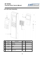
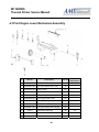
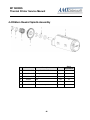
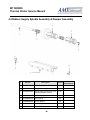
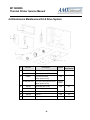
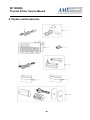
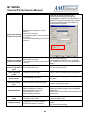
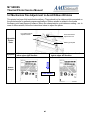
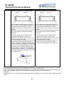
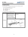
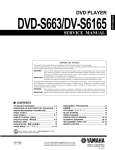
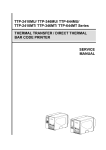
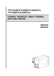
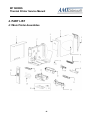
M7 SERIES
Thermal Printer Service Manual
4. PART LIST
4.1 Main Printer Assemblies
31
M7 SERIES
Thermal Printer Service Manual
No.
Part No.
1
120732
2
Description
Remark
Spare Requirement
Electronics cover
1 pc
N/A
Mainframe
1 pc
3
120733
Cover, front
1 pc
4
120734
Top right side cover
1 pc
5
120735
Cover, rear
1 pc
6
30-0240016-00LF
Media view window
1 pc
7
120736
Media supply spindle assembly
1 pc
8
98-0240021-00LF
Media damper assembly
1 set
9
120737
Ribbon sensor assembly
1 pc
10
120738
Ribbon supply spindle assembly
1 set
11
120739
Media sensor assembly
1 pc
1%
12
120740
Ribbon rewind spindle assembly
(Including gear)
1 set
1%
1%
120741
Print engine lower mechanism
assembly (Including platen roller
assembly)
1 set
13
14
120742
Screw, M3x6 (For TPH)
1 pc
120743
Print engine upper mechanism
assembly (Including print head burn
line adjustable bracket assembly)
1 set
15
120727
Printhead module (M7 PLUS/203dpi)
1 set
120728
Printhead module (M7 PLUS /300dpi)
120729
Printhead module (M7 PLUS/600dpi)
120725
Printhead module (M7/203dpi)
120726
Printhead module (M7/300dpi)
72-0240003-00LF
Printhead harness (M7 PLUS)
72-0240012-00LF
Printhead harness (M7)
72-0240021-00LF
Printhead harness (M7 PLUS 600dpi)
16
N/S
3%
1 pc
17
120744
Front lower plastic cover
1 pc
18
120745
Lower front panel
1 pc
19
120746
LCD panel assembly
1 set
32
1%
M7 SERIES
Thermal Printer Service Manual
4.2 LCD Panel Assembly
No.
Part No.
Description
Remark
1
120747
Panel plate
1 pc
2
120748
Panel cover
1 pc
3
120749
Keypad
1 pc
4
120750
LCD panel board assembly
1 pc
5
120751
Screw, TP3*8
5 pcs
33
Spare
Requirement
1%
M7 SERIES
Thermal Printer Service Manual
4.3 Print Engine Lower Mechanism Assembly
No.
Part No.
Description
Remark
1
37-1502510-34LF Screw, M2.5*10
2 pcs
2
30-0240032-00LF Print head release lever (Left)
1 pc
3
32-0240032-00LF Spring torsion
1 pc
4 37-1503006-G4LF Screw, M3*6
2 pcs
5
98-0240034-00LF Print head open sensor
1 pc
6
32-0240029-00LF Print engine lower frame
1 pc
7
30-0240033-00LF Media path cover
1 pc
8
32-0240031-10LF Shaft
1 pc
9
30-0240031-00LF Print head release lever (Right)
1 pc
10
120752
Platen roller assembly
1 set
11 32-0240030-00LF Platen holder
1 pc
12 37-1504012-54LF Screw, M4*12
2 pc
34
Spare
Requirement
3%
M7 SERIES
Thermal Printer Service Manual
4.4 Ribbon Rewind Spindle Assembly
No.
Part No.
Description
Remark
1
37-3410200-02LF E-ring, ID10*OD20*T0.6mm
2 pcs
2
32-0240036-00LF Bearing
1 pc
3
32-0240014-00LF Spring
1 pc
4
120753
Gear
1 pc
5
32-0240037-00LF Bearing
2 pcs
6
98-0240057-00LF Ribbon rewind spindle
1 set
35
Spare
Requirement
1%
M7 SERIES
Thermal Printer Service Manual
4.5 Ribbon Supply Spindle Assembly & Damper Assembly
No.
Part No.
Description
Remark
1
32-0240012-00LF Ribbon supply spindle shaft
1 pc
2
32-0240011-00LF Spring, ribbon supply spindle
2 pcs
3
98-0240059-00LF Ribbon supply spindle front cover
(Including magnet module)
1 pc
4
30-0240024-00LF Ribbon supply spindle rear cover
1 pc
5
37-1504008-54LF Screw, M4*8
1 pc
6
32-0240009-00LF Spring, damper
1 pc
7
98-0240058-00LF Media damper
1 pc
8
37-1504008-54LF Screw, M4*8
1 pc
36
Spare
Requirement
M7 SERIES
Thermal Printer Service Manual
4.6 Electronics Maintenance Kit & Drive System
No.
Part No.
1
120754
Power supply unit (M7 PLUS)
120755
Power supply unit (M7)
120806
Multi-interface board
(Dealer option for M7)
2
Description
98-0240044-00LF GPIO with multi-interface board
(Dealer option for M7)
3
4
120756
Main board (M7 PLUS)
120757
Main board (M7)
32-0240006-10LF Interface plate
Remark
1 set
Spare
Requirement
3%
1 set
Factory
option
1 set
3%
1 pc
5
120758
Gear set
1 set
1%
6
120759
Stepping motor kit
1 set
1%
37
M7 SERIES
Thermal Printer Service Manual
4.7 Option and Accessories
38
M7 SERIES
Thermal Printer Service Manual
No.
1
2
Part No.
Description
Remark
120761
Power cord / US
Standard
72-0050007-00LF
Power cord / EU
Option
72-0050007-10LF
Power cord / EU 90 degree
Option
72-0050010-10LF
Power cord / UK
Option
72-0050011-10LF
Power cord / AU
Option
72-0180003-00LF
Power cord / JP
Option
120762
External wireless print server / US
98-1000012-00LF
External wireless print server / EU
Option
120763
KU-007 Plus, programmable keyboard unit
Option
120764
KP-200, stand-alone keyboard unit
Option
120711
Bluetooth module
Option
120767
USB cable
120765
Parallel port cable
Option
120766
RS-232 cable
Option
6-1
120707
Peel-off kit (Including internal rewind +
Peel-off module)
Option
6-2
120768
Peel-off sensor assembly
Option
7
120710
Regular cutter module (Guillotine cutter)
Option
8
120760
Heavy duty cutter module (Rotary cutter)
Option
9
120708
Internal Rewinding Kit (Including Internal
Rewind + Label Redirect Front Panel)
Option
3
4
5
Standard
39
Spare
Requirement
M7 SERIES
Thermal Printer Service Manual
5. TROUBLESHOOTING
5.1 Common Problems
The following guide lists the most common problems that might be encountered when operating
this bar code printer. If the printer still does not function after all suggested solutions have been
invoked, please contact the Customer Service Department of your purchased reseller or
distributor for assistance.
Problem
Possible Cause
Power indicator does * The power cord is not properly
connected.
not illuminate
Recovery Procedure
* Plug the power cord in printer and outlet.
* Switch the printer on.
Carriage Open
* The printer carriage is open.
* Close the print carriage.
No Ribbon
* Ran out of ribbon.
* The ribbon is installed incorrectly.
* The ribbon sensor is not been well
calibrated.
* Supply a new ribbon roll.
* Refer to the user’s manual to reinstall
the ribbon.
No Paper
* Ran out of label.
* The label is installed incorrectly.
* Gap/black mark sensor is not
calibrated.
* Supply a new label roll.
* Refer to the user’s manual to reinstall the label
roll.
* Calibrate the gap/black mark sensor.
Paper Jam
* Gap/black mark sensor is not set
properly.
* Calibrate the gap/black mark sensor.
* Make sure label size is set properly.
* Set label size correctly.
* Labels may be stuck inside the printer
mechanism.
* If the peeler module is installed, remove the
label.
* If there is no peeler module in front of the printer,
turn off the printer and install it.
* Check if the connector is plugging correctly.
Take Label
* Peel function is enabled.
40
M7 SERIES
Thermal Printer Service Manual
UP:
Fwd.
DOWN:
MENU:
Rev.
Exit
Not Printing
Memory full
( FLASH / DRAM )
* Cutter jam.
* There is no cutter installed on the
printer.
* Cutter PCB is damaged.
* If the cutter module is installed, press the UP or
DOWN key to rotate the cutter knife back to the
start position.
* Remove the label.
* Make sure the thickness of label is less
than .008” (for regular cutter) or .013” (for heavy
duty cutter).
* Replace a cutter PCB.
* Re-connect cable to interface.
* If using serial cable,
- Reconnect the cable.
- Check the baud rate setting. The default baud
rate setting of printer is 9600,n,8,1.
* If using the Ethernet cable,
- Check if the Ethernet RJ-45 connector green
LED is lit on..
- Check if the Ethernet RJ-45 connector amber
LED is blinking.
- Check if the printer receives the IP address
when using DHCP mode.
- Check if the IP address is correct when using
the static IP address.
* Cable is not well connected to serial or
- Wait a few seconds, let the printer receive the
USB interface or parallel port.
communication with the server then check the
* The serial port cable pin configuration is
IP address setting again.
not pin to pin connected.
* Chang a new cable.
* Ribbon and media are not compatible.
* Verify the ribbon-inked side.
* Reload the ribbon again.
* Clean the printhead.
* The print density setting is incorrect.
* The printhead harness is partially connected.
Turn off the printer and reconnect the cable
connector.
* Check if the stepping motor cable is terminated
properly and inserted into the correct connector.
* Check your program if there is a command
PRINT at the end of the file, and CRLF at the end
of each command line.
* The space of FLASH/DRAM is full.
41
* Delete unused files in the FLASH/DRAM.
* The max. numbers of file of DRAM is 50 files.
* The max. user addressable memory space of
DRAM is 256 KB
* The max. numbers of file of FLASH is 256 files.
* The max. user addressable memory space of
FLASH is 2560 KB for M7 and 6656KB for M7
PLUS.
M7 SERIES
Thermal Printer Service Manual
* SD card is damaged.
SD card is unable to
* SD card doesn’t insert correctly.
use
* Non-approved SD card manufacturer.
* Use the supported capacity SD card.
* Insert the SD card again.
* The supported SD card spec.
- 128MB
- 256MB
- 512MB
- 1GB
- 4GB SDHC CLASS 6
* Approved SD card manufacturers; SanDisk,
Transcend
PS/2 port does not
work
* Did not turn off power prior to plug in the * Turn off printer power prior to plugging in the
PS/2 keyboard
PS/2 keyboard .
* PS/2 keyboard is damaged.
* Plug the PS/2 keyboard again.
* PS/2 keyboard cable termination.
* Return damaged keyboard for repair.
* There is no BAS file in the printer.
* Verify the BAS file has downloaded into printer.
Poor Print Quality
* Reload the supply.
* Clean the printhead.
* Clean the platen roller.
* Adjust the print density and print speed.
* Run the printer self-test to verify print pattern and
printhead performance.
* Change proper ribbon or proper label media.
* Adjust the printhead pressure adjustment knob.
- If the left side printout is too light, adjust the left
* Ribbon and media is loaded incorrectly
side pressure adjustment knob to the higher
* Dust or adhesive accumulation on the
index (higher pressure). If the pressure
print head.
adjustment knob has been adjusted to index “5”
* Print density is not set properly.
and the poor print quality is still at the left side of
the printout, adjust the pressure adjustment
* Printhead element is damaged
* Ribbon and media are incompatible.
knob to index “1” and use the Z-axis adjustment
* The printhead pressure is not set
knob to fine-tune the pressure.
- If the right side printout is too light, adjust the
properly
right side pressure adjustment knob to the
higher index (higher pressure) to improve the
print quality.
* If the label thickness is more than 0.009 inch,
and the print quality is inadequate, adjust the
heater line adjustment screw counter clockwise
to get the best print quality.
* The release lever does not latch the printhead
properly.
42
M7 SERIES
Thermal Printer Service Manual
LCD panel is dark and * The cable between main PCB and LCD * Check if the cable between main PCB and LCD
is secured or not.
keys are not working. panel is loose.
* Turn OFF and ON the printer again.
LCD panel is dark but
* The printer initialization is unsuccessful.
the LED’s are light.
* Initialize the printer.
LCD panel is dark and
LED’s are lit on, but * The LCD panel harness connector is
loose.
the label is feeding
forward.
* The LCD panel harness connector is plugged
upside down.
* The ribbon encoder sensor connector is
Ribbon encoder
* Fasten the connector.
sensor doesn’t work. loose.
Ribbon end sensor
doesn’t work.
* The connector is loose.
* Check the connector.
* The ribbon sensor hole is covered with
* Clear the dust in the sensor hole by the blower.
dust.
Peel sensor is not
working.
* Peel sensor is not located on the correct * Make sure that the media goes through the Peel
position.
sensor.
* The connector is loose.
* Plug the connect cable correctly.
Cutter is not working. * The connector is loose.
* Plug in the connect cable correctly.
Label feeding is not
* The media guide does not touch the
stable (skew) when
edge of the media.
printing.
Skips labels when
printing.
* If the label is moving to the right side, adjust the
label guide to left.
* If the label is moving to the left side, adjust the
label guide to right.
* Check if label size is setup correctly.
* Label size is not specified properly.
* Calibrate the sensor by Auto Gap or Manual Gap
* Sensor sensitivity is not set properly.
options.
* The media sensor is covered with dust.
* Clear the GAP/Black mark sensor by blower.
43
M7 SERIES
Thermal Printer Service Manual
* Calibrate the sensor sensitivity again.
* Set the correct label size and gap size.
* Press [MENU]
[SELECT] x3 [DOWN] x6
[SELECT] to fine-tune the parameter of Shift Y.
* If using the software BarTender, adjust the
vertical offset in the driver.
* Media sensor sensitivity is not set
properly.
* Label size is incorrect.
Small label printing
* The parameter Shift Y in the LCD menu
position is incorrect.
is incorrect.
* The vertical offset setting in the driver is
incorrect.
* Set the correct label size.
* Wrong label size setup.
* Press [MENU]
[SELECT] x 3
[DOWN]
The left side printout
* The parameter Shift X in LCD menu is
x5
[SELECT] to fine tune the parameter of
position is incorrect.
incorrect.
Shift X.
Missing printing on
the left or right side of
label.
RTC time is incorrect
when reboot the
printer.
Multi interface board
doesn’t work.
Power and Error
LED’s are blinking
fast.
Wrinkle Problem
* Wrong label size setup.
* Set the correct label size.
* The battery has run down.
* Check if there is a battery on the main board.
* The installation is incorrect.
* Check if the board is plugged in the right
connector.
* Power switch OFF and ON too fast.
* Turn off the printer and wait all LED’s are dark,
and turn on the printer again.
* Printhead pressure is incorrect.
* Ribbon installation is incorrect.
* Media installation is incorrect.
* Print density is incorrect.
* Media feeding is incorrect.
* Refer to chapter 5.2.
* Adjust the suitable density to have acceptable
print quality.
* Make sure the label guide touch the edge of the
media guide.
Gray line on the blank * The printhead is dirty.
* The platen roller is dirty.
label
Irregular printing
* Clean the printhead.
* Clean the platen roller.
* The printer is in Hex Dump mode.
* The RS-232 setting is incorrect.
44
* Turn off and on the printer to skip the dump
mode.
* Re-set the Rs-232 setting.
M7 SERIES
Thermal Printer Service Manual
5.2 Mechanism Fine Adjustment to Avoid Ribbon Wrinkles
This printer has been fully tested before delivery. There should not be ribbon wrinkle presented on
the printed media for general-purpose applications. Ribbon wrinkle is related to the media
thickness, print head pressure, balance, ribbon film characteristics, print darkness setting…etc. In
case of ribbon wrinkle, follow the instructions below to adjust the printer.
Print head pressure
adjustment knob
Z-axis mechanism
adjustment knob
Adjustable
Printer
Parts
Ribbon guide plate
Symptom 1. Wrinkle (missing print) occurs from lower 2. Wrinkle (missing print) occurs from lower
left to upper right direction
right to upper left direction
Wrinkle
Example
Feed direction
45
M7 SERIES
Thermal Printer Service Manual
Adjust the print head pressure adjustment knob
Left knob
Right knob
Adjust the print head pressure adjustment knob
Left knob
The print head pressure adjustment knob has 5
levels of settings. Clockwise direction adjustment is
to increase the print head pressure. Counter
Clockwise adjustment can decrease the print head
pressure.
If the wrinkle on the label starts from the lower left
side to upper right side, perform the following
adjustment.
Right knob
The print head pressure adjustment knob has 5
levels of settings. Clockwise direction adjustment is
to increase the print head pressure. Counter
Clockwise adjustment can decrease the print head
pressure.
If the wrinkle on the label starts from the lower right
side to upper left side, perform the following
adjustment.
1. Decrease the right side print head pressure
1. Decrease the left side print head pressure
adjustment knob setting 1 level per each
adjustment knob setting 1 level per each
adjustment. Print the label again to check if the
adjustment then print the label again to check if the
wrinkle (missing print) is gone.
wrinkle (missing print) is gone.
2. If the right side print head adjustment knob setting 2. If the left side print head adjustment knob level
has been set to index 1 (the lowest pressure
has been set to index 1 (the lowest index),
index), increase the left side print head pressure.
increase print head pressure on the right side.
3. If the left side print head adjustment knob setting
has been set to 5 (the highest pressure index) and
the wrinkle can’t be avoided, rotate both knobs
back to setting 1. Rotate the Z-axis mechanism
adjustment knob clockwise for a few degrees and
print again. Repeat previous steps to fine-tune the
print head pressure.
Z axis mechanism
adjustment knob
Note for step 3:
*Factory default setting, the Z-axis knob is rotated counter clockwise to the end of thread.
*Turn the Z-axis mechanism adjustment knob clockwise until you feel the knob touch the mechanism for the first adjustment.
* If the wrinkle is still there, adjust the Z-axis mechanism knob clockwise about 1/4 circle each time for
adjustment.
* If adjusting the Z-axis mechanism adjustment knob changes the winkled direction, turn the knob counter clockwise to avoid the
wrinkle.
46
M7 SERIES
Thermal Printer Service Manual
6. MAINTENANCE
This section pertains to the cleaning tools and methods used to maintain your printer.
1. Use one of following materials to clean the printer.
Cotton swab (Head cleaner pen)
Lint-free cloth
Vacuum / Blower brush
100% ethanol
2. The cleaning process is described as following:
Printer Part
Method
Interval
1. Always turn off the printer
Clean the print head when changing a
before cleaning the print head. new label roll
2. Allow the print head to cool for a
minimum of one minute.
3. Use a cotton swab (Head
cleaner pen) and 100% ethanol
to clean the print head surface.
Print Head
47
M7 SERIES
Thermal Printer Service Manual
Platen Roller
1. Turn the power off.
2. Rotate the platen roller and
wipe it thoroughly with 100%
ethanol and a cotton swab, or
lint-free cloth.
Tear Bar/Peel
Bar
Use the lint-free cloth with 100% As needed
ethanol to wipe it.
Sensor
Exterior
Compressed air or vacuum
Interior
Brush or vacuum
Clean the platen roller when changing a
new label roll
Monthly
Wipe it with water-dampened cloth As needed
As needed
Note:
Do not touch the print head by hand. If needed, use ethanol to clean it.
Only use 100% Ethanol. DO NOT use medical alcohol, which may damage the printer head.
Clean the print head and supply sensors each time the ribbon is replaced to maintain
performance and extend printer life.
48
M7 SERIES
Thermal Printer Service Manual
UPDATE HISTORY
Date
1 JUN 09
Content
Production Release
Editor
JFN
AMT DATASOUTH CORPORATION
5033 Sirona Drive, Suit #800
Charlotte, NC 28273
704-523-8500
49